CN111852209A - Lock with a locking mechanism - Google Patents
Lock with a locking mechanism Download PDFInfo
- Publication number
- CN111852209A CN111852209A CN202010259166.0A CN202010259166A CN111852209A CN 111852209 A CN111852209 A CN 111852209A CN 202010259166 A CN202010259166 A CN 202010259166A CN 111852209 A CN111852209 A CN 111852209A
- Authority
- CN
- China
- Prior art keywords
- lock
- braking
- brake
- housing
- locking
- Prior art date
- Legal status (The legal status is an assumption and is not a legal conclusion. Google has not performed a legal analysis and makes no representation as to the accuracy of the status listed.)
- Pending
Links
- 239000012777 electrically insulating material Substances 0.000 claims description 3
- 238000002360 preparation method Methods 0.000 claims 1
- 229920001971 elastomer Polymers 0.000 description 9
- 239000000806 elastomer Substances 0.000 description 9
- 238000010292 electrical insulation Methods 0.000 description 2
- 230000005484 gravity Effects 0.000 description 2
- 230000001960 triggered effect Effects 0.000 description 2
- 230000002426 anti-panic effect Effects 0.000 description 1
- 230000015572 biosynthetic process Effects 0.000 description 1
- 239000002131 composite material Substances 0.000 description 1
- 230000006835 compression Effects 0.000 description 1
- 238000007906 compression Methods 0.000 description 1
- 238000010276 construction Methods 0.000 description 1
- 230000005489 elastic deformation Effects 0.000 description 1
- 238000003780 insertion Methods 0.000 description 1
- 230000037431 insertion Effects 0.000 description 1
- 239000004922 lacquer Substances 0.000 description 1
- 239000000463 material Substances 0.000 description 1
- 239000002184 metal Substances 0.000 description 1
- 238000000034 method Methods 0.000 description 1
Images


Classifications
-
- E—FIXED CONSTRUCTIONS
- E05—LOCKS; KEYS; WINDOW OR DOOR FITTINGS; SAFES
- E05B—LOCKS; ACCESSORIES THEREFOR; HANDCUFFS
- E05B65/00—Locks or fastenings for special use
- E05B65/10—Locks or fastenings for special use for panic or emergency doors
- E05B65/1086—Locks with panic function, e.g. allowing opening from the inside without a ley even when locked from the outside
-
- E—FIXED CONSTRUCTIONS
- E05—LOCKS; KEYS; WINDOW OR DOOR FITTINGS; SAFES
- E05B—LOCKS; ACCESSORIES THEREFOR; HANDCUFFS
- E05B63/00—Locks or fastenings with special structural characteristics
- E05B63/14—Arrangement of several locks or locks with several bolts, e.g. arranged one behind the other
- E05B63/146—Arrangement of several locks or locks with several bolts, e.g. arranged one behind the other locks with two or more bolts, each bolt itself being a tumbler
-
- E—FIXED CONSTRUCTIONS
- E05—LOCKS; KEYS; WINDOW OR DOOR FITTINGS; SAFES
- E05B—LOCKS; ACCESSORIES THEREFOR; HANDCUFFS
- E05B15/00—Other details of locks; Parts for engagement by bolts of fastening devices
-
- E—FIXED CONSTRUCTIONS
- E05—LOCKS; KEYS; WINDOW OR DOOR FITTINGS; SAFES
- E05B—LOCKS; ACCESSORIES THEREFOR; HANDCUFFS
- E05B15/00—Other details of locks; Parts for engagement by bolts of fastening devices
- E05B15/16—Use of special materials for parts of locks
-
- E—FIXED CONSTRUCTIONS
- E05—LOCKS; KEYS; WINDOW OR DOOR FITTINGS; SAFES
- E05B—LOCKS; ACCESSORIES THEREFOR; HANDCUFFS
- E05B17/00—Accessories in connection with locks
- E05B17/0045—Silencing devices; Noise reduction
-
- E—FIXED CONSTRUCTIONS
- E05—LOCKS; KEYS; WINDOW OR DOOR FITTINGS; SAFES
- E05B—LOCKS; ACCESSORIES THEREFOR; HANDCUFFS
- E05B59/00—Locks with latches separate from the lock-bolts or with a plurality of latches or lock-bolts
Landscapes
- Engineering & Computer Science (AREA)
- Structural Engineering (AREA)
- Business, Economics & Management (AREA)
- Emergency Management (AREA)
- Braking Arrangements (AREA)
Abstract
The invention relates to a lock, comprising: a lock case (2); a lock element (7) arranged in the lock housing (2), wherein the lock element (7) is movably arranged relative to the lock housing (2) parallel to the lock plane (8); and a detent device (20) arranged in the lock housing (2) and having a detent element (25) and a resilient restoring element (27), wherein the detent element (25) can be moved perpendicular to the lock plane (8) against a restoring force of the restoring element (27), and wherein the detent element (25) and the lock element (7) are arranged such that the lock element (7) strikes the detent element (25) during its movement, so that the detent element (25) is moved perpendicular to the lock plane (8) against the restoring force.
Description
Technical Field
The present invention relates to a lock. The lock is designed in particular for insertion into a door leaf. In a preferred embodiment a panic lock.
Background
The locks considered here generally comprise a plurality of movable lock elements in or at the lock box. The lock element is, for example, a bolt or a bolt, but can also be a plurality of components within the lock housing, which contribute to the movement and/or locking of the bolt or bolt, for example. When the lock element is moved in or at the lock box, undesirable noise development can occur.
Disclosure of Invention
The object of the invention is to provide a lock in which the noise development triggered by the movement of at least one lock element of the lock is reduced as much as possible.
The object is solved by the features of the invention. The following has an advantageous embodiment of the subject matter of the invention.
The object is thus achieved by a lock. The lock includes a lock box. In particular, the lock case is composed of a lock plate and a lock cover. The lock housing does not necessarily have to be formed from sheet metal, but can also be made, for example, from plastic or from a composite material. Nevertheless, the common name "lock plate" is used. The lock plate forms, inter alia, a rear wall and a plurality of side walls of the lock case. The locking plate is closed via the locking cover, so that a lock case is formed by the locking plate and the locking cover.
At least one lock element is present in the lock box. The lock element may also be only partially arranged in the lock box and possibly protruding from the lock box, such as for example a latch or a tongue. The lock element is here movable relative to the lock housing and parallel to the lock plane.
Furthermore, the lock comprises a braking device arranged in the lock housing. The braking device comprises a braking element and an elastic resetting element. The elastic restoring element, for example as an elastomer element in the embodiments yet to be described, can also be an integral component of the braking element.
The braking element is movable against a resetting force of the resetting element. The detent element is preferably movable perpendicular to the latching plane against the reset force of the reset element.
The detent element and the lock element are arranged such that the lock element strikes the detent element during its movement. By striking the braking element, the braking element can be moved against the restoring force. By striking the detent element, the detent element can preferably be moved perpendicular to the latching plane against the restoring force.
In particular, the locking element strikes against the catch element in its final position during movement. It is possible for the locking element to rest against the braking element in the final position.
During braking, the locking element presses the braking element against a resetting force. In this case, the braking element is pressed in particular perpendicularly to the lock plane. In this case, it is basically sufficient if at least one movement vector of the braking element is perpendicular to the locking plane. Preferably, it is provided that the larger motion vector is perpendicular to the lock plane.
During braking, the lock element moves the braking element in one direction. Due to the resetting force, a counter force in the opposite direction acts on the locking element at the same time. As a result, the locking element rubs and is correspondingly braked at the braking element and/or at least one further bearing element or guide element of the locking element. By braking, the noise development, which may occur when the lock element is moved into its final position, is reduced. At the same time, the load on the lock element is reduced, since the lock element does not move into its final position at full speed.
Preferably, during braking, the lock element moves the braking element in one direction perpendicular to the lock plane. Due to the restoring force, counter forces act on the locking element, preferably simultaneously, in opposite directions, also perpendicular to the locking plane.
The lock may comprise a locking element, in particular a latch. The locking element is movable along a locking element axis to lock the door. The locking element axis may extend parallel to the lock plane.
In principle, the lock elements described herein may be the lock bolts or deadbolts of the locks.
In a preferred embodiment, it is however proposed that the lock comprises, in addition to the lock element, a bolt which can be moved parallel to the lock plane along a bolt axis in order to lock the lock. In addition to the deadbolt, the lock preferably includes at least one bolt. The locking plane is in particular designed such that it is parallel to the connecting line from the bolt to the bolt.
The locking plane is in particular parallel to the locking plate and to the locking cover.
The lock may also include a toggle member. The toggle element usually has an opening, for example a square opening, for inserting a door handle or a panic lever. The opening in the toggle member is preferably perpendicular to the lock plane. Furthermore, the lock may preferably comprise an opening for inserting the lock cylinder. The opening for the lock cylinder is preferably likewise perpendicular to the lock plane.
The lock element described here is particularly preferably designed as a slide. It is possible that the locking element, in particular the latch, can be pulled in by means of the slide by means of the rotary toggle. Alternatively or additionally, the locking element can be unlocked by rotating the toggle piece by means of the slide.
In a preferred embodiment, the lock is designed as a panic lock.
In the design of the lock as a "panic lock", the following mechanical means are provided inside the lock case, which can be implemented: the latch is pulled in by rotating the toggle, for example via a door handle. Accordingly, the lock element, in this case in the form of a slide plate, is operatively connected to the bolt and the driver of the lock, so that by rotating the driver, the bolt can be pulled in via the slide plate. The slide thus transmits the rotational movement of the toggle member to the translational movement of the latch.
In particular, the lock element, which is designed as a slide plate, is guided in the lock housing so as to be linearly movable.
It is possible that the locking element, in particular the slide plate, can be moved into its final position by means of a spring. Preferably, the braking device brakes the movement into this end position, which is caused by the spring. It is possible that in another end position the braking device according to the invention is not provided. Rather, the movement of the lock element into the other end position is braked by a spring. Thereby, noise formation is avoided.
Preferably, the arresting device arrests the movement of the lock element in the direction of gravity in the installed lock. In the movement in the direction of gravity, there is an increased noise development without a braking device. It is thus possible that the braking device is preferably in the final position of the lower part of the slide. The braking device can in particular be located on the side of the bolt facing away from the bolt.
It is possible that the arresting device arrests the movement of the lock element that causes the locking of the door. If the lock element is designed as a slide, the movement of the slide which causes the movement of the bolt out of the lock housing is braked.
It is possible that the detent device is designed to press the lock element against the inside of the lock housing in the event of a crash. In particular, the inside of the lock case may be the inside of the lock cover.
It can be provided that a locking element, for example, which is designed as a sliding plate, is guided in a sliding manner on the inside of the lock housing. In particular, the locking element is guided in a sliding manner on the inner side of the locking cap. It is particularly preferred, however, that the lock elements, in particular the inner sides of the slide plate and/or the lock case, are coated with a slip-on lacquer. The detent device is preferably designed to press the lock element against the inner side in the event of a crash. The locking of the locking element is achieved here by increased friction between the locking element and the inner side, which is triggered by the restoring force of the restoring element.
Alternatively, the lock element can be guided at a distance from the inside of the lock housing. It is conceivable that the detent device presses the lock element onto the inside of the lock housing only upon impact.
It is furthermore preferably provided that the braking element and/or the impact region of the locking element have a surface which is inclined toward the locking plane. The "impact region" of the lock element is the region of the lock element which is in contact with the braking element during the braking process. The impact can be achieved by at least one inclined surface.
The restoring element of the brake device is according to a preferred embodiment a spring, in particular a helical spring. The spring compresses upon impact. In this case, the braking element is moved against the restoring force, in particular perpendicularly to the locking plane. At the same time, the compressed spring exerts an opposing force on the lock element via the detent element, in particular also perpendicularly to the lock plane.
Furthermore, it may alternatively be provided that the restoring element is designed as an elastomer element. Such an element made of an elastomer material can be elastically deformed accordingly and exerts a restoring force on it.
In this case, it is also possible for the elastomer element to be an integral component of the braking element. In this case, the locking element directly contacts the elastomer element or a hard layer applied to the elastomer element. In both cases, the elastic deformation of the elastomer element and the corresponding restoring force occur directly.
Furthermore, the return element can also be formed by a combination of a spring and an elastomer element. The elastomer element can be located, for example, inside or outside the spring.
In a preferred embodiment, it is provided that the restoring force of the restoring element is settable. The setting is performed by means of a setting mechanism. The setting mechanism may be configured as an adjusting screw. In the embodiment of the return element as a spring, the compression of the spring is set by means of such an adjusting mechanism, in particular by means of such an adjusting screw. In particular, it is proposed here that the spring bears against the adjusting screw.
In a preferred embodiment, it is provided that the setting means, in particular the adjusting screw, is positioned such that it is accessible from the outside of the lock case. For example, the setting means, in particular the adjusting screw, protrudes into a hole in the lock case or is accessible via such a hole in the lock case.
In a further preferred embodiment, it is provided that the braking device comprises a brake arm. In particular, the braking element comprises a braking arm. The brake arm is pivotably constructed. The brake arm is particularly pivotable about a rotational axis. A corresponding shaft can be provided on the rotational axis, which shaft is fixedly supported on the brake housing.
The brake arm can be formed integrally and/or materially integrally with the rest of the brake element.
Furthermore, it is also possible for the detent elements, in particular in the form of teeterboard elements, to roll by means of curved surfaces; in this case, there is no need for a shaft to be present on the axis of rotation.
It is possible that the braking element, in particular the braking arm, comprises an inclined face. The inclined face may be inclined such that the lock element slides along the face.
It is conceivable that the detent arm can be pivoted such that the tip of the detent arm pivots when the lock element strikes against the detent arm. In particular, the tip of the brake arm pivots away from the lock element. By pivoting it is possible for the braking force acting on the locking element to rise steplessly upon impact.
The inclined face may include a rounded portion. The rounding can be flattened in the braking direction of the lock element. It is thereby possible that the lock element can continue to slide along the inclined surface despite the pivoting of the brake arm. In particular, the tilting is cancelled. The rounding can be formed by means of a plurality of radii extending into one another.
The axis of rotation is preferably parallel to the lock plane.
The braking element is preferably designed as a seesaw. The seesaw is characterized in that the seesaw extends on both sides of the rotation axis. On one side of the axis of rotation there is a stop arm, on the other side of the axis of rotation the return element acts on the seesaw. As already described, the seesaw may be supported at the axis of rotation via a shaft. Alternatively, it is also possible for the seesaw to roll on the support via the arched outer surface.
It is furthermore preferably provided that the brake system comprises a brake housing. At least one braking element and a restoring element are arranged in or on the brake housing.
In a preferred embodiment, a braking element, which is in particular designed as a seesaw, is present in or on the brake housing. In particular, the brake housing is a separate component which is connected, in particular releasably connected without damage, to the lock housing. Preferably, the brake housing is screwed to the lock case.
Preferably, the restoring element, in particular a restoring element designed as a spring, is located in a cavity of the brake housing. The restoring element is preferably supported by one side on the detent element, preferably in the form of a seesaw detent element. In particular, the setting mechanism is at least partially accommodated in the brake housing. Preferably, the setting mechanism, which is designed as an adjusting screw, is accommodated in a thread of the brake housing. In particular, the restoring element, in particular a spring, is supported on the end of the setting mechanism, in particular the adjusting screw.
It is furthermore preferably provided that the brake housing comprises eyelets which are inserted for positioning of the brake housing on guide pins which are fixed to the lock housing. The eyelet can be inserted directly on the guide pin or on a further element, for example on a bearing, which is in turn inserted on the guide pin.
In particular, the lock has said bolt. The locking bar is preferably guided on a guide pin so as to be linearly movable. The same guide pin is preferably also plugged with an eye of the brake housing.
The brake housing may be constructed of an electrically insulating material. In particular, the brake housing may be arranged between the circuit board and the lock housing. Thereby, the brake housing can be used as an electrical insulation.
The lock may comprise a stop for limiting the movement of the lock element. The stop may be disposed outside the inclined surface. Thereby, an abrupt end of the movement of the lock element at the brake device is avoided. Preferably, the stop is arranged outside the braking element. Particularly preferably, the stop is arranged outside the brake system. For example, the lock element may comprise a slot. Pins or rollers may be provided in the elongated holes. A pin or roller may be used as a stop. For example, the elongated hole can be designed as a sliding groove for the movement of the locking element, in particular of the latch. The locking element, in particular the latch, may comprise said pin or roller and thus said stop.
Drawings
The invention will now be elucidated in detail on the basis of an embodiment. Shown here are:
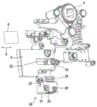
figure 1 shows a schematic view of a lock according to the invention according to one embodiment,
figure 2 shows a detail of the lock according to the invention according to this embodiment,
Fig. 3 shows a detail of the lock according to the invention according to this embodiment, with the lock element (slide plate) hidden,
fig. 4 shows a braking device of a lock according to the invention according to this embodiment, and
fig. 5 shows the brake device in fig. 4 with the brake housing concealed.
Detailed Description
One embodiment of the lock 1 is shown in detail below with reference to figures 1 to 5. The lock 1 is configured as a mortise lock (as a panic lock) having an anti-panic function.
In the following, all fig. 1 to 5 are always referred to unless otherwise stated.
The lock 1 comprises a lock case 2. The lock case 2 forms the housing of the lock 1 and serves to accommodate or support the individual components. The lock case 2 includes a lock plate 3 and a lock cover. The lock cover encloses the lock plate 3. In the figures, the lock cover is hidden so that the internal construction of the lock 1 is visible.
Furthermore, the lock 1 comprises a toggle element 4 with corresponding toggle arm and an opening, which is here embodied as a quadrilateral, for inserting a handle. The bolt 5 and the bolt 6 extend from the lock 1. For the sake of overview, all components of the lock 1 are not shown in the figures. Thus, in particular, further mechanical and/or electronic components can be provided in the lock 1 in order to perform the movement within the lock 1.
The lock 1 further comprises a lock element 7, which is designed here as a slide. The lock element 7 is operatively connected not only to the driver 4 but also to the locking bolt 6. In the illustrated position according to fig. 1, the lock element 7 can be lifted by means of the toggle element 4, whereby the locking bolt 6 is pulled in. In particular, the lock 1 satisfies an anti-terrorist function due to the design of the lock element 7 as a slide.
The bolt 6 is guided on a guide pin 10 so as to be linearly movable along a bolt axis 9.
A lock plane 8 is defined at the lock 1. The locking plane 8 is parallel to the rear wall formed by the locking plate 3 or to a locking cover, not shown. Furthermore, the lock plane 8 is parallel to the latch axis 9 and perpendicular to the opening in the toggle 4. The locking element 7 is linearly movable in said locking plane 8.
Fig. 1 shows a lock 1 with a lock element 7. Fig. 2 shows a detail view, in which the locking plate 3 is hidden. In fig. 3, the locking element 7 is additionally hidden. As can be seen in particular from fig. 2 and 3, the lock 1 comprises a braking device 20. In detail, fig. 4 and 5 show the brake device 20.
The brake apparatus 20 includes a brake housing 21. The brake housing 21 in turn comprises an eyelet 22. The eyelet 22 is inserted on the guide pin 10, on which the locking bar 6 is guided in a linearly movable manner. Via the eyelet 22 and via the guide pin 10, the brake housing 21 is positioned within the lock housing 2. Furthermore, the brake housing 21 is connected with the lock case 2 via two threaded fasteners 23.
The brake housing 21 is hidden in fig. 5. As is shown in particular in the overview of fig. 4 and 5, the brake system 20 comprises a brake element 24 within the brake housing 21. The braking element 24 is designed here as a seesaw. The brake element 24 is rotatable or pivotable about a rotation axis 26 relative to the brake housing 21. By being configured as a seesaw, one portion of the braking element 24 is located on one side of the axis of rotation 26 and the other portion is located on the opposite side of the axis of rotation 26.
The axis of rotation 26 need not necessarily be formed by a corresponding shaft. It is therefore also sufficient for the curved portion of the brake element 24 to roll relative to the brake housing 21. In general terms, this is therefore a virtual axis of rotation 26.
On one side of the axis of rotation 26 there is a brake arm 25 on the brake element 24. On the other side of the axis of rotation 26, a restoring element 27 acts on the braking element 24.
The brake arm 25 has an inclined face 29. The lock element 7 strikes against the detent arm 25 during its movement. The brake arm 25 is thus moved at least with a motion vector perpendicular to the lock plane 8. In this case, the movement is directed in the direction of the locking plate 3. At the same time, the other side of the braking element 24 moves with at least one motion vector which is likewise perpendicular to the locking plane 8, but in the opposite direction; in this case in the direction of the locking cap. The restoring element 27, in this case a restoring element in the form of a helical spring, is compressed.
Via the restoring element 27, a restoring force acts on the braking element 24. The reset force presses the locking element 7 in the direction of the locking cap. By striking, the lock element 7 is pressed onto the lock cover. Thereby performing braking.
During braking, the lock element 7 continues to slide along the inclined face 29.
The inclined surface 29 has a rounded portion. The rounding is formed by means of a plurality of radii extending into one another. As a result, the locking element 7 first strikes flat against the inclined surface. The locking element 7 is pressed onto the locking cover by pivoting of the detent arm 25 and by the reduced curvature without tilting.
It is possible for the locking element 7, i.e. the slide plate, to be guided in a sliding manner on the locking cover. By means of the reset force, the latch element 7 is pressed against the guide surface, whereby braking takes place.
Fig. 4 and 5 show that an adjusting screw 28, in this case designed as a countersunk screw, is provided in the brake housing 21. The resetting element 27 is supported on the adjusting screw 28. The restoring force can thereby be adjusted by means of the adjusting screw 28. In the lock case 2, there is a hole in the lock cover at the location of the adjusting screw 28 in the example shown, so that the adjusting screw 28 is accessible from the outside.
The brake housing 21 is made of an electrically insulating material. The brake housing 21 is disposed between a not-shown circuit board and the lock case 2, whereby the brake housing 21 serves as an electrical insulation portion.
The lock 1 comprises a stop 30 for limiting the movement of the lock element 7. The latch 6 comprises the stop 30. The stop 30 is guided in an elongated hole 31 of the locking element 7. The elongated hole 31 serves as a slide for the movement of the latch 6. If the lock element 7 is moved downwards, the bolt 6 is removed from the lock case 2 in the following manner: the stop 30 is guided in the slot 31. The stop 30 is designed as a pin or as a roller. By the stop 30 being arranged outside the brake device 20, the movement of the lock element 7 is limited outside the brake device 20, so that particularly gentle braking is possible.
The braking device 20 brakes the movement of the lock element 7 into the lower end position, which is shown in fig. 1. The lock element 7 is moved into the lower final position by the force of the spring 32 (see fig. 1). The upper end position of the lock element 7 is conversely achieved by the rotation of the toggle 4 against the force of the spring 32. In the lower end position of the lock element 7, the locking bar 6 is moved out.
In the scope of this embodiment, a brake device 20 for braking a slide is explained in detail. However, the brake device 20 can also be used for any other movable component in the lock box 2. The component to be braked does not necessarily have to perform a linear movement here, but rather can also perform a rotary or pivoting movement in the lock housing 2.
List of reference numerals:
1 Lock
2 Lock the case
3 lock plate
4 toggle piece
5 bolt
6 lock bolt
7 Lock element, in particular a skateboard
8 lock plane
9 latch axis
10 guide pin
20 brake device
21 brake housing
22 holes
23 screw fastener
24-detent arm, in particular seesaw
25 braking element
26 axis of rotation
27 reset element
28 adjusting screw
29 inclined plane
30 stop
31 long hole, chute
32 spring
Claims (15)
1. A lock, comprising:
a lock case (2),
a lock element (7) arranged in the lock case (2), wherein the lock element (7) is movable relative to the lock case (2) parallel to a lock plane (8), and
a braking device (20) arranged in the lock housing (2) and having a braking element (24) and a resilient return element (27),
wherein the braking element (24) is movable against a resetting force of the resetting element (27), in particular perpendicularly to the locking plane (8), and
wherein the detent element (24) and the lock element (7) are arranged such that the lock element (7) strikes the detent element (25) when it is moved and thereby moves the detent element (24), in particular perpendicularly to the lock plane (8), against the restoring force.
2. A lock as claimed in claim 1, wherein the lock is of the type described in claim 1,
wherein the lock element (7) is designed as a slider, wherein the slider is operatively connected to a locking element (6) and a toggle lever (4) of the lock (1), in particular such that by rotation of the toggle lever (4) the locking element (6) can be pulled in and/or unlocked via the slider, wherein a movement of the slider (7), in particular caused by a spring (32), is braked by the brake device (20).
3. Lock (1) according to any one of the preceding claims,
the braking device (20) is designed to press the locking element (7) against the inside of the lock housing during a crash.
4. Lock (1) according to any one of the preceding claims,
wherein the braking element (24) and/or the impact region of the lock element (7) has a face (9) which is inclined towards the lock plane (8).
5. Lock (1) according to any one of the preceding claims,
wherein the resetting force of the resetting element (27) is settable; in particular by means of a setting mechanism, in particular an adjusting screw (28), accessible from outside the lock case (2).
6. Lock (1) according to any one of the preceding claims,
wherein the brake device (20) comprises a pivotable brake arm (25), wherein in particular the brake element (24) comprises the brake arm (25).
7. Lock (1) according to any one of the preceding claims,
wherein the braking element (24), in particular the braking arm (25), has the face (29), wherein the face (29) is inclined such that the lock element (7) slides along the face (29).
8. Lock (1) according to any one of the preceding claims,
it is characterized in that the preparation method is characterized in that,
The brake arm (25) can be pivoted such that the tip of the brake arm (25) pivots when the lock element (7) strikes against the brake arm (25).
9. Lock (1) according to any one of the preceding claims,
wherein the surface (29) comprises a rounding, wherein the rounding is flattened in the braking direction of the lock element (7), in particular the rounding is formed by means of a plurality of radii extending into one another.
10. Lock (1) according to any one of the preceding claims,
wherein the braking element (24) is designed as a seesaw, wherein the braking arm (25) is on one side of the rotational axis (26) of the braking element (24) and the restoring element (27) acts on the other side of the rotational axis (26).
11. Lock (1) according to any one of the preceding claims,
wherein the brake device (20) comprises a brake housing (21), in and/or on which the brake element (24) and the restoring element (27) are arranged, wherein the brake housing (21) is connected, preferably screwed, to the lock housing (2).
12. Lock (1) according to claim 11,
wherein the brake housing (21) comprises an eyelet (22) which is inserted on a guide pin (10) fixed to the lock box to position the brake housing (21).
13. Lock (1) according to claim 12,
wherein the bolt (6) of the lock (1) is guided on the guide pin (10) in a linearly movable manner.
14. Lock (1) according to any one of the preceding claims,
wherein the brake housing (21) is made of an electrically insulating material, wherein in particular the brake housing (21) is arranged between a circuit board and the lock housing (2).
15. Lock (1) according to any one of the preceding claims,
wherein the lock (1) comprises a stop (30) for limiting the movement of the lock element (7), wherein the stop (30) is arranged outside the inclined surface (29), preferably outside the braking element (24), particularly preferably outside the braking device (20).
Applications Claiming Priority (2)
| Application Number | Priority Date | Filing Date | Title |
|---|---|---|---|
| EP19172070.5A EP3733998A1 (en) | 2019-04-30 | 2019-04-30 | Lock |
| EP19172070.5 | 2019-04-30 |
Publications (1)
| Publication Number | Publication Date |
|---|---|
| CN111852209A true CN111852209A (en) | 2020-10-30 |
Family
ID=66349421
Family Applications (1)
| Application Number | Title | Priority Date | Filing Date |
|---|---|---|---|
| CN202010259166.0A Pending CN111852209A (en) | 2019-04-30 | 2020-04-03 | Lock with a locking mechanism |
Country Status (2)
| Country | Link |
|---|---|
| EP (1) | EP3733998A1 (en) |
| CN (1) | CN111852209A (en) |
Cited By (1)
| Publication number | Priority date | Publication date | Assignee | Title |
|---|---|---|---|---|
| CN117605357A (en) * | 2023-12-29 | 2024-02-27 | 泰州市爱利特金属制品有限公司 | A multi-point lock for doors and windows |
Families Citing this family (1)
| Publication number | Priority date | Publication date | Assignee | Title |
|---|---|---|---|---|
| CN113685091A (en) * | 2021-08-25 | 2021-11-23 | 中山市逸家安防科技有限公司 | Lock body link gear with function of fleing fast |
Citations (5)
| Publication number | Priority date | Publication date | Assignee | Title |
|---|---|---|---|---|
| DE4337969A1 (en) * | 1993-10-15 | 1995-04-20 | Theodor Krachten | Self-locking safety door lock |
| EP1970507A2 (en) * | 2007-03-13 | 2008-09-17 | Dorma Gmbh & Co. Kg | Anti panic lock |
| CN103422736A (en) * | 2012-05-23 | 2013-12-04 | 多玛两合有限公司 | Lock for a door |
| CN105041054A (en) * | 2015-06-18 | 2015-11-11 | 北京安恒利通科技股份公司 | Escape fireproof lock and application method thereof |
| CN108884689A (en) * | 2016-03-10 | 2018-11-23 | Kfv卡尔弗利特有限及两合公司 | lock |
Family Cites Families (1)
| Publication number | Priority date | Publication date | Assignee | Title |
|---|---|---|---|---|
| DE202007016556U1 (en) * | 2007-11-26 | 2009-04-02 | Schulte-Schlagbaum Aktiengesellschaft | Lock with silenced trap |
-
2019
- 2019-04-30 EP EP19172070.5A patent/EP3733998A1/en not_active Withdrawn
-
2020
- 2020-04-03 CN CN202010259166.0A patent/CN111852209A/en active Pending
Patent Citations (5)
| Publication number | Priority date | Publication date | Assignee | Title |
|---|---|---|---|---|
| DE4337969A1 (en) * | 1993-10-15 | 1995-04-20 | Theodor Krachten | Self-locking safety door lock |
| EP1970507A2 (en) * | 2007-03-13 | 2008-09-17 | Dorma Gmbh & Co. Kg | Anti panic lock |
| CN103422736A (en) * | 2012-05-23 | 2013-12-04 | 多玛两合有限公司 | Lock for a door |
| CN105041054A (en) * | 2015-06-18 | 2015-11-11 | 北京安恒利通科技股份公司 | Escape fireproof lock and application method thereof |
| CN108884689A (en) * | 2016-03-10 | 2018-11-23 | Kfv卡尔弗利特有限及两合公司 | lock |
Cited By (1)
| Publication number | Priority date | Publication date | Assignee | Title |
|---|---|---|---|---|
| CN117605357A (en) * | 2023-12-29 | 2024-02-27 | 泰州市爱利特金属制品有限公司 | A multi-point lock for doors and windows |
Also Published As
| Publication number | Publication date |
|---|---|
| EP3733998A1 (en) | 2020-11-04 |
Similar Documents
| Publication | Publication Date | Title |
|---|---|---|
| US5570915A (en) | Flush-mounted door latch | |
| CA2892809C (en) | Electric latch retraction device for vertical rod door latches | |
| CA2733403C (en) | High strength electric door strike with gravity fed locking member | |
| US11585118B2 (en) | Door lock device | |
| CN111852209A (en) | Lock with a locking mechanism | |
| US7497488B2 (en) | Rotary latch | |
| US20090031768A1 (en) | Cylinder lock, clutch device and unlocking device comprising thereof | |
| US20190203503A1 (en) | Electric door lock device | |
| US7895868B2 (en) | Cylinder lock and unlocking device comprising thereof | |
| US20020163206A1 (en) | Swinging elevator hatchway door interlock | |
| JPH09510042A (en) | Safety switch | |
| CA2629838C (en) | Electromechanical rotary lock cylinder | |
| US7697277B1 (en) | Auto-depress disk drive bracket mechanism | |
| CN119737088A (en) | Electric oil tank lock | |
| US20090031771A1 (en) | Cylinder lock and unlocking device comprising thereof | |
| CN108868390B (en) | Vehicle locking device | |
| JP2006233696A (en) | Sliding door lock set | |
| US5661275A (en) | Self adjusting switch mechanism | |
| JP3693129B2 (en) | External circuit handle device for circuit breaker | |
| CN211818684U (en) | Full-automatic lock body triggering and back-locking device | |
| JPH0624530Y2 (en) | Flat handle device | |
| JP4405693B2 (en) | Door to door | |
| JP4828276B2 (en) | Locking bolt side pressure reduction structure of locking device | |
| CN211115195U (en) | A locking device for a gun cabinet | |
| JPH0225898Y2 (en) |
Legal Events
| Date | Code | Title | Description |
|---|---|---|---|
| PB01 | Publication | ||
| PB01 | Publication | ||
| SE01 | Entry into force of request for substantive examination | ||
| SE01 | Entry into force of request for substantive examination | ||
| WD01 | Invention patent application deemed withdrawn after publication | ||
| WD01 | Invention patent application deemed withdrawn after publication |
Application publication date: 20201030 |