CN111844327A - Assembly method of circulating tray - Google Patents
Assembly method of circulating tray Download PDFInfo
- Publication number
- CN111844327A CN111844327A CN201910342760.3A CN201910342760A CN111844327A CN 111844327 A CN111844327 A CN 111844327A CN 201910342760 A CN201910342760 A CN 201910342760A CN 111844327 A CN111844327 A CN 111844327A
- Authority
- CN
- China
- Prior art keywords
- clamping
- panel
- hole
- tray
- connecting piece
- Prior art date
- Legal status (The legal status is an assumption and is not a legal conclusion. Google has not performed a legal analysis and makes no representation as to the accuracy of the status listed.)
- Pending
Links
- 238000000034 method Methods 0.000 title claims abstract description 40
- 238000004064 recycling Methods 0.000 claims description 3
- 239000002023 wood Substances 0.000 abstract description 12
- 238000004519 manufacturing process Methods 0.000 abstract description 7
- 230000009286 beneficial effect Effects 0.000 abstract description 3
- 239000003381 stabilizer Substances 0.000 description 16
- 239000004033 plastic Substances 0.000 description 13
- 229920003023 plastic Polymers 0.000 description 13
- 238000006073 displacement reaction Methods 0.000 description 6
- 230000005489 elastic deformation Effects 0.000 description 4
- 230000008901 benefit Effects 0.000 description 3
- 238000011084 recovery Methods 0.000 description 3
- 230000008878 coupling Effects 0.000 description 2
- 238000010168 coupling process Methods 0.000 description 2
- 238000005859 coupling reaction Methods 0.000 description 2
- 238000003825 pressing Methods 0.000 description 2
- 238000004891 communication Methods 0.000 description 1
- 238000010276 construction Methods 0.000 description 1
- 230000001066 destructive effect Effects 0.000 description 1
- 238000010586 diagram Methods 0.000 description 1
- 238000001125 extrusion Methods 0.000 description 1
- 238000003780 insertion Methods 0.000 description 1
- 230000037431 insertion Effects 0.000 description 1
- 238000009434 installation Methods 0.000 description 1
- 239000000463 material Substances 0.000 description 1
- 238000003860 storage Methods 0.000 description 1
- 239000002699 waste material Substances 0.000 description 1
Images


Classifications
-
- B—PERFORMING OPERATIONS; TRANSPORTING
- B27—WORKING OR PRESERVING WOOD OR SIMILAR MATERIAL; NAILING OR STAPLING MACHINES IN GENERAL
- B27M—WORKING OF WOOD NOT PROVIDED FOR IN SUBCLASSES B27B - B27L; MANUFACTURE OF SPECIFIC WOODEN ARTICLES
- B27M3/00—Manufacture or reconditioning of specific semi-finished or finished articles
- B27M3/0013—Manufacture or reconditioning of specific semi-finished or finished articles of composite or compound articles
Landscapes
- Engineering & Computer Science (AREA)
- Life Sciences & Earth Sciences (AREA)
- Manufacturing & Machinery (AREA)
- Wood Science & Technology (AREA)
- Forests & Forestry (AREA)
- Connection Of Plates (AREA)
Abstract
The invention discloses an assembling method of a circulating tray, relates to the technical field of logistics transportation, and solves the problem that the existing wood tray is not beneficial to disassembly and reassembly of the wood tray due to the nail-nailing connection forming mode. The circulating tray comprises a panel, a connecting piece and supporting legs, wherein the connecting piece is detachably connected with the panel and the supporting legs respectively, and the assembling method comprises the following steps: 1, mounting holes are arranged on a panel; 2 inserting the connecting piece into the panel mounting hole; 3, turning the panel for 180 degrees; and 4, aligning the support legs with the connecting pieces, applying force to connect the support legs with the connecting pieces, and completing assembly. The disassembling method comprises the following steps: and (4) extruding the support legs along the direction opposite to the force application direction in the step (4) to ensure that the support legs are completely separated from the connecting piece, and taking down the connecting piece on the panel. The invention changes the production mode of the traditional tray, changes the binding type of the tray into the assembly type, has simple process and improves the production efficiency; the support legs and the connecting pieces are universal pieces, so that the tray parts can be recycled and assembled, the tray parts can be recycled, and data are saved.
Description
Technical Field
The invention relates to the technical field of logistics transportation, in particular to an assembling method of a circulating tray.
Background
The definition of the Chinese national standard "logistic terms" to the tray (pallet) is: horizontal platform apparatus for containerizing, stacking, handling and transporting cargo and articles placed as unit loads. As a kind of container equipment similar to a container, the pallet is widely used in the fields of production, transportation, storage and circulation, and is considered as one of two key innovations in the logistics industry of the 20 th century. The pallet is used as important loading, unloading, storing and transporting equipment in the logistics operation process, and plays a great role in modern logistics in cooperation with a forklift. The benefits brought to the modern logistics industry by the tray are mainly reflected in that: the unitization, standardization and standardization of the article package can be realized, the articles are protected, and the logistics and the commodity flow are facilitated.
The quantity of the pallet market circulation in China is 2.7 hundred million sheets each year, wherein about 80 percent of the wood pallets are distributed, and the wood pallets are still mainly processed simply and conveniently and have low cost. The thriving wood pallet demand is accompanied by a severe consumption of wood and disposal problems for the waste pallets. At present, the wood pallet is mainly formed by connecting and nailing nails, and the connecting mode is basically disposable, needs destructive disassembly and is difficult to disassemble and low in efficiency. This connection is not conducive to disassembly and reassembly of the wooden pallet.
Disclosure of Invention
The invention aims to: the invention provides an assembling method of a circulating tray, aiming at solving the problem that the existing wooden tray is not beneficial to the disassembly and the reassembly of the wooden tray by adopting a nail nailing connection forming mode.
The invention specifically adopts the following technical scheme for realizing the purpose:
a method of assembling a recycling tray, the recycling tray including a panel, a connecting member and a leg, the connecting member being detachably connected to the panel and the leg, respectively, the method comprising the steps of: (1) mounting holes are formed in the panel; (2) inserting the connector into the panel mounting hole; (3) turning the panel with the connector connected thereto through 180 °; (4) and aligning the support legs with the connecting pieces, applying force to enable the support legs to be matched and connected with the connecting pieces, and finishing the assembly of the circulating tray. When the panel is made of wood, mounting holes are carved in the panel and are matched with the connecting pieces. According to the invention, the connecting piece is inserted into the panel through the mounting hole, one end of the connecting piece is clamped in the panel mounting hole, and the other end of the connecting piece is connected with the support leg to form the tray, so that the production mode of the traditional tray is changed, the tray is assembled in an assembly mode instead of a binding mode, the assembly process is simple, and the production efficiency is improved; correspondingly, the disassembly method of the circulation tray is the reverse process of the assembly method: and (4) extruding the support legs along the direction opposite to the force application direction in the step (4) to enable the support legs to be completely separated from the connecting piece, and taking down the connecting piece on the panel to finish the disassembly process of the circulating tray. After the disassembly, the panel, the connecting piece and the support legs are shipped in a part mode, so that the transportation cost is low; the support legs and the connecting pieces are universal pieces, so that the tray parts can be recycled and assembled, the tray parts can be recycled, and data are saved.
Preferably, in the step (4), the force application directions of the adjacent support legs are opposite. I.e. the assembly direction of adjacent legs is opposite, so that the direction of the forces causing relative displacement of the panel and legs in use of the circulating tray is opposite, the resultant force is small, i.e. the tray is not prone to relative displacement of the panel and legs in use.
Preferably, the connecting piece is including being equipped with cardboard, riser and joint spare, riser one end and cardboard fixed connection, the riser other end and joint spare integrated into one piece, joint spare tip interval is greater than the through hole tip interval of mounting hole, be equipped with on the stabilizer blade with joint spare assorted screens hole, joint spare can dismantle with the screens hole and be connected. The panel is made of wood, the connecting piece is made of plastic, rectangular clamp plate holes are engraved on the panel, and through holes are engraved in the clamp plate holes. The connecting piece is "pi" type, riser and joint spare all have two, and during the equipment, the cardboard is located the cardboard hole department of mounting hole, because two joint spare both ends outside interval is greater than two through hole both ends intervals, extrudees two risers and makes two joint spare outer tip intervals less than or equal to the outer tip interval of mounting hole through hole, and the joint spare passes the through hole, and joint spare and cardboard are located the panel both sides respectively, and connecting piece plastics elasticity recovery part deformation, joint spare joint in through hole department for the connecting piece is firm with the panel joint. The cardboard includes the horizontal plate and is located the hang plate of horizontal plate both sides, the hang plate inclines to the inside of mounting hole, during the assembly the hang plate contacts earlier with the panel, and the horizontal plate is unsettled for the upper surface of connecting piece is the arch, and domes produce elastic deformation tension when assembling the stabilizer blade, and tension perpendicular to panel makes panel, stabilizer blade and connecting piece assembly more firm reliable. Meanwhile, the plastic support legs generate downward elastic deformation tension on the arched upper surface of the connecting piece, so that the upper surfaces of the clamping plate and the panel are smooth after the assembly is finished, and the clamping plate and the panel are convenient to actually circulate and use.
Preferably, the cross section of joint spare is fan ring shape, the cross section in screens hole is for the fan ring shape with joint spare assorted, the fan ring shape internal diameter of joint spare is less than screens hole fan ring shape internal diameter, the screens hole is the blind hole, screens hole upper end one side and stabilizer blade upper surface intercommunication. The joint piece inserts the screens hole from the department of lining up in screens hole, realizes being connected with dismantling in screens hole the joint piece, screens hole upper end one side and stabilizer blade upper surface intercommunication be convenient for the connecting piece and remove when the assembly.
Preferably, when the supporting legs are matched with the connecting piece, the circle center of the sector ring of the clamping piece coincides with the circle center of the sector ring of the clamping hole. So that the assembly of the support legs and the connecting piece is firmer and more reliable.
Preferably, the central angle of the sector ring of the clamping piece is 220-240 degrees. The support legs and the connecting pieces are not easy to slip after the assembly is completed, and the support legs and the connecting pieces are further assembled firmly and reliably.
Preferably, the clamping hole comprises a vertical groove and a sector annular groove which are communicated, the upper end of the vertical groove is communicated with the upper surface of the support leg, the cross section of the sector annular groove is sector annular, the vertical groove is matched with the vertical plate, and the sector annular groove is matched with the clamping piece. When the assembly is completed, the upper part of the vertical plate of the connecting piece penetrates through the panel mounting hole, and the lower part of the vertical plate of the connecting piece is clamped in the vertical groove.
Preferably, the joint spare includes middle part joint spare and the tip joint spare that is located middle part joint spare both ends, the radius of middle part joint spare equals, the radius of tip joint spare is followed the junction of tip joint spare and middle part joint spare and is crescent to the tip, and tip joint spare is tubaeform promptly. Correspondingly, the screens hole includes middle part screens hole and the tip screens hole that is located middle part screens hole both ends, the radius in middle part screens hole equals, the radius in tip screens hole is crescent to tip screens hole from the junction in tip screens hole and middle part screens hole, and tip screens hole is tubaeform promptly. The clamping piece of the connecting piece in the step (4) is inserted into the clamping hole of the supporting leg to play a role in guiding.
Preferably, in the step (4), the clamping hole of the supporting leg is aligned with the clamping piece of the connecting piece to apply force to press the supporting leg, so that the clamping hole is clamped with the clamping piece.
Preferably, the stabilizer blade includes a plurality of supporting shoes and a plurality of support bar, and is a plurality of the supporting shoe comprises support bar body coupling and constitutes the stabilizer blade, every all be equipped with on the supporting shoe with joint spare assorted screens hole, the support bar upper surface makes things convenient for fork truck and hydraulic pressure car to advance the fork for the arch.
The invention has the following beneficial effects:
1. according to the invention, the connecting piece is inserted into the panel through the mounting hole, one end of the connecting piece is clamped in the panel mounting hole, and the other end of the connecting piece is connected with the support leg to form the tray, so that the production mode of the traditional tray is changed, the tray is assembled in an assembly mode instead of a binding mode, the assembly process is simple, and the production efficiency is improved; correspondingly, the disassembly method of the circulation tray is the reverse process of the assembly method: and (4) extruding the support legs along the direction opposite to the force application direction in the step (4) to enable the support legs to be completely separated from the connecting piece, and taking down the connecting piece on the panel to finish the disassembly process of the circulating tray. After the disassembly, the panel, the connecting piece and the support legs are shipped in a part mode, so that the transportation cost is low; the support legs and the connecting pieces are universal pieces, so that the tray parts can be recycled and assembled, the tray parts can be recycled, and data are saved.
2. When the clamping holes of the support legs are aligned with the clamping pieces of the connecting piece in the step (4) to apply force to extrude the support legs, the fan-shaped inner diameter of the clamping pieces is smaller than that of the fan-shaped inner diameter of the clamping holes, so that the clamping pieces are in interference fit with the clamping holes, and the support legs and the connecting piece are connected more firmly and reliably.
3. In the step (4) of the invention, the force application directions of the adjacent support legs are opposite. I.e. the assembly direction of adjacent legs is opposite, so that the direction of the forces causing relative displacement of the panel and legs in use of the circulating tray is opposite, the resultant force is small, i.e. the tray is not prone to relative displacement of the panel and legs in use.
4. When the support legs are matched with the connecting piece, the circle center of the sector ring of the clamping piece is superposed with the circle center of the sector ring of the clamping hole, so that the support legs and the connecting piece are assembled more firmly and reliably; the sector-shaped central angle of the clamping piece is 220-240 degrees, so that the supporting legs and the connecting piece are not easy to slip after the assembly is completed, and the assembly of the supporting legs and the connecting piece is further firm and reliable.
Drawings
FIG. 1 is a schematic view of a panel of the present invention after installation of mounting holes;
FIG. 2 is a schematic view of the construction of the connector of the present invention;
FIG. 3 is a schematic view of the structure of the stand bar of the present invention;
FIG. 4 is a schematic structural view of step (2) of the present invention;
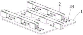
FIG. 5 is a schematic view of the connector of the present invention assembled with a panel and turned 180 degrees;
FIG. 6 is a schematic structural view of step (4) of the present invention;
FIG. 7 is a schematic view of the back of the assembled recycle tray of the present invention;
FIG. 8 is a schematic structural view of the front side of the assembled recirculation tray of the present invention;
FIG. 9 is a partial schematic view of the assembled connecting member and support leg of the present invention;
FIG. 10 is a schematic view of the disassembled structure of the circulation tray of the present invention;
FIG. 11 is a schematic view of the circulation tray of the present invention after the legs are disengaged from the connectors during the removal process;
Reference numerals: 1-panel, 11-mounting hole, 12-panel chamfer, 2-leg, 21-support block, 22-retaining hole, 23-support bar, 24-mounting groove, 25-vertical groove, 26-fan-ring groove, 3-connecting piece, 31-horizontal plate, 32-inclined plate, 33-vertical plate, 34-clamping piece, 35-connecting piece chamfer, 4-leg extension piece, 41-mounting piece, 42-matching groove.
Detailed Description
In order to make the objects, technical solutions and advantages of the embodiments of the present invention clearer, the technical solutions in the embodiments of the present invention will be clearly and completely described below with reference to the drawings in the embodiments of the present invention, and it is obvious that the described embodiments are some, but not all, embodiments of the present invention. The components of embodiments of the present invention generally described and illustrated in the figures herein may be arranged and designed in a wide variety of different configurations.
Thus, the following detailed description of the embodiments of the present invention, presented in the figures, is not intended to limit the scope of the invention, as claimed, but is merely representative of selected embodiments of the invention. All other embodiments, which can be derived by a person skilled in the art from the embodiments given herein without making any creative effort, shall fall within the protection scope of the present invention.
It should be noted that: like reference numbers and letters refer to like items in the following figures, and thus, once an item is defined in one figure, it need not be further defined and explained in subsequent figures. Furthermore, the terms "first," "second," and the like are used merely to distinguish one description from another, and are not to be construed as indicating or implying relative importance.
In the description of the embodiments of the present invention, it should be noted that the terms "inside", "outside", "upper", and the like indicate orientations or positional relationships based on the orientations or positional relationships shown in the drawings or orientations or positional relationships conventionally arranged when products of the present invention are used, and are only used for convenience in describing the present invention and simplifying the description, but do not indicate or imply that the devices or elements indicated must have specific orientations, be constructed in specific orientations, and operated, and thus, cannot be construed as limiting the present invention.
Example 1
As shown in fig. 1 to 9, the present embodiment provides a circulation tray, which includes a panel 1, support legs 2 and connecting members 3, wherein the panel 1 is provided with mounting holes 11, the mounting holes 11 are matched with the connecting members 3, and the connecting members 3 pass through the mounting holes 11 to detachably connect the panel 1, the connecting members 3 and the support legs 2.
The panel 1 is made of wood, and the support legs 2 and the connecting pieces 3 are made of plastics. Can utilize the advantage of each material comprehensively like this, practice thrift timber resources, and plastics stabilizer blade 2 and plastic connecting piece 3 have elasticity, make things convenient for the equipment and the dismantlement of tray, plastics stabilizer blade 2 and plastic connecting piece 3 can recycle as the commonality simultaneously, and for traditional tray is whole, use cost is lower.
The cross section of joint spare 34 is fan-shaped ring, the cross section of screens hole 22 is for the fan-shaped ring with joint spare 34 assorted, the fan-shaped ring internal diameter of screens spare 34 is less than the fan-shaped internal diameter of screens hole 22, screens hole 22 is the blind hole, screens hole 22 upper end one side and stabilizer blade 2 upper surface intercommunication. The connecting piece 3 is inserted into the clamping hole 22 from the through position of the clamping hole 22, and the vertical plate 33 is used for moving at the communication position of the clamping hole 22 and the upper surface of the support leg 2, so that the detachable connection of the connecting piece 3 and the support leg 2 is realized. When the support leg 2 is matched with the connecting piece 3, the circle center of the sector ring of the clamping piece 34 is superposed with the circle center of the sector ring of the clamping hole 22, so that the support leg 2 and the connecting piece 3 are assembled more firmly and reliably.
Furthermore, the central angle of the sector ring of the clamping piece 34 is 220-240 degrees, so that the support leg 2 and the connecting piece 3 are not easy to slip after the assembly is completed, and the support leg 2 and the connecting piece 3 are further assembled firmly and reliably.
Further, the clamping hole 22 comprises a vertical groove 25 and a sector annular groove 26 which are communicated, the upper end of the vertical groove 25 is communicated with the upper surface of the support leg 2, the cross section of the sector annular groove 26 is sector annular, the vertical groove 25 is matched with the vertical plate 33, and the sector annular groove 26 is matched with the clamping piece 34. When the assembly is completed, the upper part of the vertical plate 33 of the connecting piece 3 penetrates through the mounting hole 11 of the panel 1, and the lower part of the vertical plate 33 of the connecting piece 3 is clamped in the vertical groove 25.
The joint 34 includes middle part joint spare and the tip joint spare that is located middle part joint spare both ends, the radius of middle part joint spare equals, the radius of tip joint spare is crescent to the tip from the junction of tip joint spare and middle part joint spare, and tip joint spare is tubaeform promptly. The size and the 34 phase-matchs of joint spare of screens hole 22, screens hole 22 includes middle part screens hole and the tip screens hole that is located middle part screens hole both ends promptly, the radius in middle part screens hole equals, the radius in tip screens hole is crescent to tip screens hole from the junction in tip screens hole and middle part screens hole, and tip screens hole is tubaeform promptly. This arrangement guides the insertion of the snap-in member 34 into the capture aperture 22.
The assembling method of the circulating tray comprises the following steps: (1) the panel 1 is provided with a mounting hole 11, when the panel 1 is made of wood, a rectangular clamping plate hole is engraved on the panel 1, and a through hole is engraved on the clamping plate hole, wherein the clamping plate hole is matched with a clamping plate of the connecting piece, and the through hole is matched with the clamping piece 34, as shown in fig. 1; (2) the connecting piece 3 is made of plastic, and the connecting piece 3 is inserted into the mounting hole 11 of the panel 1 according to the arrow direction shown in figure 4: extruding the two vertical plates 33 to enable the distance between the outer end parts of the two clamping pieces 34 to be smaller than or equal to the distance between the outer end parts of the through holes of the mounting holes, enabling the clamping pieces 34 to penetrate through the through holes, enabling the clamping pieces 34 and the clamping plates to be respectively positioned at two sides of the panel 1, enabling the plastic elastic recovery parts of the connecting pieces 3 to deform, and enabling the clamping pieces 34 to be clamped at the through holes to enable the connecting pieces 3 to be firmly clamped with; (3) turning the panel 1 connected with the connecting piece 3 by 180 degrees, and turning the panel as shown in figure 5; (4) aligning the support leg 2 with the connecting piece 3, applying force to press the support leg 2 according to the arrow direction shown in fig. 6 to ensure that the support leg 2 is matched and connected with the connecting piece 3, wherein the pressing stroke is more than 150mm, and the assembly of the circulating tray is completed.
As shown in fig. 6, in the step (4), the clamping holes 22 of the support legs 2 are aligned with the clamping pieces 34 of the connecting piece 3, and force is applied to press the support legs 2, so that the clamping holes 22 are in interference fit with the clamping pieces 34. The force application directions of the adjacent support legs 2 are opposite. I.e. the assembly direction of adjacent legs 2 is opposite, so that the directions of the forces causing relative displacement of the panel 1 and the legs 2 in use of the circulating tray are opposite, the resultant force is small, i.e. the tray is not prone to relative displacement of the panel 1 and the legs 2 in use. The stabilizer blade 2 includes a plurality of supporting shoe 21 and a plurality of support bar 23, and is a plurality of stabilizer blade 2 is constituteed by support bar 23 body coupling to supporting shoe 21, every all be equipped with on the supporting shoe 21 with 34 assorted screens holes 22 of joint spare, support bar 23 upper surface is the arch, makes things convenient for fork truck and hydraulic pressure car to advance the fork.
Example 2
As shown in fig. 10 to 11, the present embodiment provides a method of disassembling the recycle tray in embodiment 1: the disassembly method is the reverse process of the assembly method: and (3) pressing the support legs 2 along the arrow direction shown in fig. 10 to completely separate the support legs 2 from the connecting pieces 3, wherein fig. 11 is a schematic structural diagram of the support legs 2 separated from the connecting pieces 3 in the process of disassembling the circulation tray, and the connecting pieces 3 on the panel 1 are removed to complete the disassembling process of the circulation tray. After the disassembly, the panel 1, the connecting piece 3 and the support legs 2 are shipped in a part mode, so that the transportation cost is low; the supporting legs 2 and the connecting pieces 3 are universal parts, so that the tray parts can be recycled and assembled, the tray parts can be recycled, and data can be saved.
Claims (10)
1. A method of assembling a recycling tray comprising a panel, a connecting member and a leg, wherein the connecting member is detachably connected to the panel and the leg, respectively, the method comprising the steps of: (1) mounting holes are formed in the panel; (2) inserting the connector into the panel mounting hole; (3) turning the panel with the connector connected thereto through 180 °; (4) and aligning the support legs with the connecting pieces, applying force to enable the support legs to be matched and connected with the connecting pieces, and finishing the assembly of the circulating tray.
2. The method of assembling a circulation tray according to claim 1, wherein in the step (4), the force application directions of the adjacent legs are opposite.
3. The method for assembling a circulating tray of claim 1, wherein the connecting member comprises a clamping plate, a vertical plate and a clamping member, one end of the vertical plate is fixedly connected with the clamping plate, the other end of the vertical plate is integrally formed with the clamping member, the distance between the end parts of the clamping member is larger than that between the end parts of the through holes of the mounting holes, the supporting legs are provided with clamping holes matched with the clamping member, and the clamping member is detachably connected with the clamping holes.
4. The method for assembling a circulation tray according to claim 3, wherein the cross section of the engaging member is a fan-shaped ring, the cross section of the engaging hole is a fan-shaped ring matching with the engaging member, the inner diameter of the fan-shaped ring of the engaging member is smaller than the inner diameter of the fan-shaped ring of the engaging hole, the engaging hole is a blind hole, and one side of the upper end of the engaging hole is communicated with the upper surface of the leg.
5. The method of assembling a circulation tray according to claim 4, wherein the center of the sector ring of the snap-in member coincides with the center of the sector ring of the snap-in hole when the legs are engaged with the connectors.
6. The method of assembling a circulation tray according to claim 3, wherein the central angle of the sector of the snap-in member is 220 ° to 240 °.
7. The method of assembling a circulation tray according to claim 3, wherein the locking holes comprise a vertical groove and a sector annular groove which are communicated with each other, the upper end of the vertical groove is communicated with the upper surface of the support leg, the sector annular groove has a sector annular cross section, the vertical groove is matched with the vertical plate, and the sector annular groove is matched with the locking member.
8. The assembling method of the circulation tray according to claim 3, wherein the clamping members include a middle clamping member and end clamping members positioned at both ends of the middle clamping member, the middle clamping member has the same radius, and the radius of the end clamping members is gradually increased from the connecting position of the end clamping members and the middle clamping member to the end; the screens hole includes middle part screens hole and the tip screens hole that is located middle part screens hole both ends, the radius in middle part screens hole equals, the radius in tip screens hole increases gradually to tip screens hole from the junction in tip screens hole and middle part screens hole.
9. The method for assembling a circulation tray according to claim 3, wherein in the step (4), the clamping holes of the support legs are aligned with the clamping pieces of the connecting pieces, and the support legs are pressed by applying force to clamp the support legs, so that the clamping holes are clamped with the clamping pieces.
10. The method for assembling a circulation tray according to any one of claims 1 to 9, wherein the support bar comprises a plurality of support blocks and a plurality of support bars, the support blocks are integrally connected by the support bars to form the support bar, each support block is provided with a locking hole matched with the locking member, and the upper surface of the support bar is arched.
Priority Applications (1)
| Application Number | Priority Date | Filing Date | Title |
|---|---|---|---|
| CN201910342760.3A CN111844327A (en) | 2019-04-26 | 2019-04-26 | Assembly method of circulating tray |
Applications Claiming Priority (1)
| Application Number | Priority Date | Filing Date | Title |
|---|---|---|---|
| CN201910342760.3A CN111844327A (en) | 2019-04-26 | 2019-04-26 | Assembly method of circulating tray |
Publications (1)
| Publication Number | Publication Date |
|---|---|
| CN111844327A true CN111844327A (en) | 2020-10-30 |
Family
ID=72952456
Family Applications (1)
| Application Number | Title | Priority Date | Filing Date |
|---|---|---|---|
| CN201910342760.3A Pending CN111844327A (en) | 2019-04-26 | 2019-04-26 | Assembly method of circulating tray |
Country Status (1)
| Country | Link |
|---|---|
| CN (1) | CN111844327A (en) |
Citations (11)
| Publication number | Priority date | Publication date | Assignee | Title |
|---|---|---|---|---|
| US3220078A (en) * | 1963-08-08 | 1965-11-30 | Elastic Stop Nut Corp | Rotary fastener |
| WO1996028357A1 (en) * | 1995-03-16 | 1996-09-19 | Juan Antonio Borrell Galve | Improved pallet |
| CN1276329A (en) * | 2000-06-09 | 2000-12-13 | 上海尚思图文设计有限公司 | Multi-segment inserted paper pallet |
| WO2012073149A1 (en) * | 2010-12-01 | 2012-06-07 | Konsortium Two In One | Modular pallet |
| CN202798222U (en) * | 2012-07-12 | 2013-03-13 | 胡赛高 | Improved structure of motor rotor |
| CN205186766U (en) * | 2015-12-04 | 2016-04-27 | 上海弘河包装技术有限公司 | A tray foot and prefabricated tray for prefabricating tray |
| CN105966728A (en) * | 2016-05-13 | 2016-09-28 | 苏州尚迪新材料有限公司 | Novel assembling type tray |
| WO2017110330A1 (en) * | 2015-12-25 | 2017-06-29 | ニッタ株式会社 | Shaft connection structure |
| CN107949708A (en) * | 2015-06-30 | 2018-04-20 | 宾工程工厂公司 | Clamping snap-fit fasteners |
| CN108013558A (en) * | 2018-01-30 | 2018-05-11 | 深圳市优美而耐洋伞有限公司 | With the umbrella of snap fit connection umbrella cloth |
| CN207860805U (en) * | 2018-01-03 | 2018-09-14 | 广州金发碳纤维新材料发展有限公司 | A kind of bolt-type composite pallet |
-
2019
- 2019-04-26 CN CN201910342760.3A patent/CN111844327A/en active Pending
Patent Citations (11)
| Publication number | Priority date | Publication date | Assignee | Title |
|---|---|---|---|---|
| US3220078A (en) * | 1963-08-08 | 1965-11-30 | Elastic Stop Nut Corp | Rotary fastener |
| WO1996028357A1 (en) * | 1995-03-16 | 1996-09-19 | Juan Antonio Borrell Galve | Improved pallet |
| CN1276329A (en) * | 2000-06-09 | 2000-12-13 | 上海尚思图文设计有限公司 | Multi-segment inserted paper pallet |
| WO2012073149A1 (en) * | 2010-12-01 | 2012-06-07 | Konsortium Two In One | Modular pallet |
| CN202798222U (en) * | 2012-07-12 | 2013-03-13 | 胡赛高 | Improved structure of motor rotor |
| CN107949708A (en) * | 2015-06-30 | 2018-04-20 | 宾工程工厂公司 | Clamping snap-fit fasteners |
| CN205186766U (en) * | 2015-12-04 | 2016-04-27 | 上海弘河包装技术有限公司 | A tray foot and prefabricated tray for prefabricating tray |
| WO2017110330A1 (en) * | 2015-12-25 | 2017-06-29 | ニッタ株式会社 | Shaft connection structure |
| CN105966728A (en) * | 2016-05-13 | 2016-09-28 | 苏州尚迪新材料有限公司 | Novel assembling type tray |
| CN207860805U (en) * | 2018-01-03 | 2018-09-14 | 广州金发碳纤维新材料发展有限公司 | A kind of bolt-type composite pallet |
| CN108013558A (en) * | 2018-01-30 | 2018-05-11 | 深圳市优美而耐洋伞有限公司 | With the umbrella of snap fit connection umbrella cloth |
Similar Documents
| Publication | Publication Date | Title |
|---|---|---|
| US20220144487A1 (en) | Pallet | |
| CN113602630B (en) | Combined plastic pallet | |
| CN104828363A (en) | Combined type double-face panel pallet for logistics | |
| CN210162435U (en) | Detachable circulating tray | |
| CN210063672U (en) | Detachable circulating tray | |
| CN111844327A (en) | Assembly method of circulating tray | |
| CN203428163U (en) | Combined plastic tray | |
| CN210063676U (en) | Connecting assembly of circulating tray | |
| CN102233966A (en) | Combined pallet | |
| CN210162436U (en) | Coupling assembling and can dismantle circulation tray of constituteing thereof | |
| CN213499811U (en) | Wooden tray processing work platform | |
| CN216377359U (en) | Forklift base plate | |
| CN204548756U (en) | A kind of logistics dull and stereotyped pallet of Combined double-face | |
| KR200441940Y1 (en) | Prefab pallet | |
| KR20080006142U (en) | Prefab pallet | |
| CN201214505Y (en) | heat-sealed plastic tray | |
| CN201801016U (en) | Assembled waterproof pallet | |
| KR20080006143U (en) | Prefab pallet | |
| WO2016064345A1 (en) | A pallet assembly | |
| KR200290472Y1 (en) | The palette for loading goods | |
| KR100464733B1 (en) | The palette for loading goods and it's assembly method | |
| CN209650789U (en) | A kind of Combined changable pallet | |
| CN105644891A (en) | Material transferring tray | |
| CN206202923U (en) | A kind of pallet profiled metal pin pier | |
| CN207450563U (en) | A kind of combined type logistics tray |
Legal Events
| Date | Code | Title | Description |
|---|---|---|---|
| PB01 | Publication | ||
| PB01 | Publication | ||
| SE01 | Entry into force of request for substantive examination | ||
| SE01 | Entry into force of request for substantive examination | ||
| RJ01 | Rejection of invention patent application after publication |
Application publication date: 20201030 |
|
| RJ01 | Rejection of invention patent application after publication |