Disclosure of Invention
Based on the defects of the prior art, the invention aims to provide a long-stroke position detection device and method with low cost and low power consumption aiming at the long-stroke position detection requirement.
In order to achieve the purpose, the invention provides the following scheme:
a long-stroke position detecting device comprising: the permanent magnet and the detection circuit board;
the permanent magnet is fixedly arranged on the movable component at the position to be detected, and the permanent magnet linearly displaces along with the movable component; the detection circuit board is used for detecting the position of the permanent magnet in real time;
the detection circuit board is a PCB; the PCB comprises a magnetic sensor array, a multi-channel gating module, a signal conditioning module, an analog-to-digital conversion module and a microprocessor module which are electrically connected in sequence;
the magnetic field sensitive plane of the magnetic sensor array is coincident with or parallel to the magnetic field plane of the permanent magnet, and a set interval is kept between the magnetic sensor array and the permanent magnet;
the multi-channel gating module is used for performing signal gating on the analog signals output by the magnetic sensor array according to a gating instruction sent by the microprocessor module to obtain selective analog signals; the signal conditioning module is used for conditioning the selected analog signal to obtain a conditioned analog signal; the analog-to-digital conversion module is used for converting the conditioning analog signal into a digital signal; the microprocessor module is used for determining the position of the permanent magnet according to the digital signal, and further determining the position of the movable component.
Preferably, the number of the PCB boards is one or more;
when the number of the PCB boards is multiple, the multiple PCB boards are connected in series along the detection direction.
Preferably, the PCB board further includes: an identity ID recognition module;
the identity ID recognition module is electrically connected with the microprocessor module;
and when the number of the PCBs is multiple, the identity ID identification module is used for detecting and identifying the zero offset position of the PCB corresponding to the identity ID identification module.
Preferably, the identity ID identification module is composed of a dial switch.
Preferably, the magnetic sensor array comprises a plurality of magnetic sensing chips;
the magnetic sensing chips are arranged at set intervals;
the magnetic field generated by the permanent magnet enables at least two magnetic sensing chips in the magnetic sensor array to reach magnetic saturation.
Preferably, the PCB further comprises an interface module;
the interface module is electrically connected with the microprocessor module;
when the number of the PCBs is multiple, the interface module is used for transmitting an output signal in the current PCB to the next PCB or the upper computer;
when the number of the PCBs is 1, the interface module is used for transmitting output signals in the PCBs to an upper computer;
the interface module is a wireless communication interface module or a wired interface module.
Preferably, the multiple gating module is composed of a plurality of analog switches.
Preferably, the microprocessor module comprises a memory unit;
the storage unit is used for storing and/or reading and writing data input into the microprocessor module.
Preferably, the PCB board includes a power module;
the power supply module is a current source or a voltage source; the power module is used for providing working electric energy for the PCB.
A long stroke position detection method is applied to the long stroke position detection device; the long-stroke position detection method comprises the following steps:
sequentially carrying out gating power supply on the magnetic sensing chip through a multi-path gating module, reading the digital signals conditioned and converted by the signal conditioning module and the analog-to-digital conversion module, and recording the digital signals as initial signals for storage;
acquiring all stored initial signals, and determining the initial position of the permanent magnet according to all the acquired initial signals;
according to the initial position, gating power supply is carried out on the magnetic sensing chips corresponding to the initial position through a multi-path gating module, and according to the position change of the permanent magnet, gating power supply is carried out on the next magnetic sensing chip, the previous magnetic sensing chip or N magnetic sensing chips adjacent to the current magnetic sensing chip in advance, and analog signals output by all the magnetic sensing chips are collected in real time;
and determining the moving position of the permanent magnet according to the analog signal so as to complete the real-time detection of the position of the movable component.
According to the specific embodiment provided by the invention, the invention discloses the following technical effects:
according to the long-stroke position detection device and method provided by the invention, the magnetic sensor array is adopted, so that the influence of magnetic field harmonic waves and an external stray magnetic field on the detection precision is avoided, and the long-stroke position detection device and method have the advantages of high linearity, capability of reducing errors caused by non-uniform air gaps and the like. And by adopting the multi-channel gating module and the microprocessor module, only the analog signals output by the magnetic sensor array close to or about to the current position to be detected are subjected to signal gating, so that the detection real-time performance is ensured, the channel number of the synchronous analog-digital converter and the complexity of a conditioning circuit structure are reduced, and low power consumption is realized.
Detailed Description
The technical solutions in the embodiments of the present invention will be clearly and completely described below with reference to the drawings in the embodiments of the present invention, and it is obvious that the described embodiments are only a part of the embodiments of the present invention, and not all of the embodiments. All other embodiments, which can be derived by a person skilled in the art from the embodiments given herein without making any creative effort, shall fall within the protection scope of the present invention.
The invention aims to provide a long-stroke position detection device and method with low cost and low power consumption aiming at the long-stroke position detection requirement.
In order to make the aforementioned objects, features and advantages of the present invention comprehensible, embodiments accompanied with figures are described in further detail below.
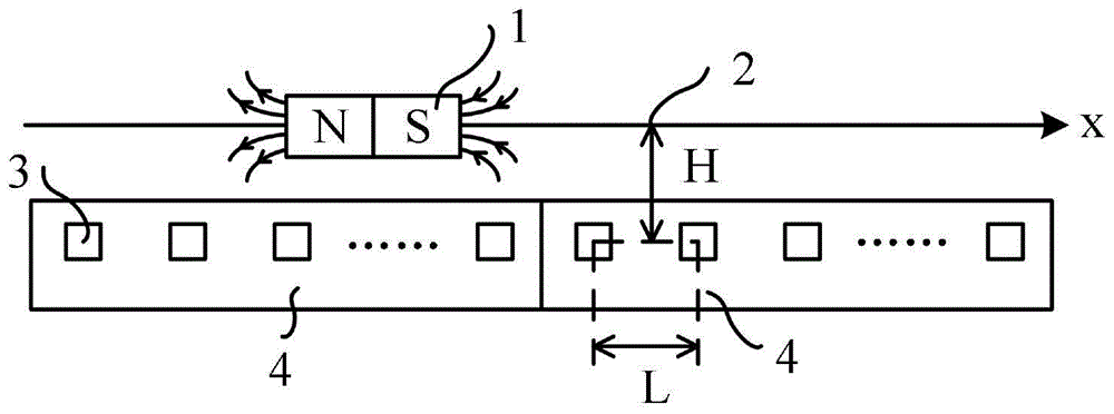
Fig. 1 is a first layout view of a structure of a long stroke position detecting device provided by the present invention, and fig. 2 is a second layout view of the structure of the long stroke position detecting device provided by the present invention. As shown in fig. 1 and 2, a long stroke position detecting apparatus includes: permanent magnet 1 and detection circuit board 4.
The permanent magnet 1 is fixedly mounted on a movable member at a position to be detected, and the permanent magnet 1 linearly displaces (such as a straight line, a curve, an arc line and the like) along with the movable member. The detection circuit board 4 is used for detecting the position of the permanent magnet in real time.
The shape of the permanent magnet 1 is not limited, the material is preferably high-magnetic neodymium iron boron, but not limited, and other materials such as samarium cobalt, ferrite, alnico and the like also belong to the protection scope of the patent. The magnetic field generated by the permanent magnet is preferably a sine wave magnetic field.
As shown in fig. 1 and 2, the permanent magnet 1 is preferably a single-pole magnet that moves linearly along the rail 2 in the present invention, in the example of a linear motion along the X direction, but the linear motion may be a motion along an arbitrary straight line or curved line in the present invention.
The detection circuit board 4 is a PCB (Printed circuit board). The PCB board includes a magnetic sensor array, a multi-way gating module, a signal conditioning module, an analog-to-digital conversion module, and a microprocessor module (here, none of the modules are shown in fig. 1 and 2) which are electrically connected in sequence.
The magnetic field sensitive plane of the magnetic sensor array is coincident with or parallel to the magnetic field plane of the permanent magnet 1, and a set interval is kept between the magnetic sensor array and the permanent magnet 1.
And the multi-path gating module is used for performing signal gating on the analog signals output by the magnetic sensor array according to the gating instruction sent by the microprocessor module to obtain the selection analog signals. The signal conditioning module is used for conditioning the selected analog signal to obtain a conditioned analog signal. The analog-to-digital conversion module is used for converting the conditioning analog signal into a digital signal. The microprocessor module is used for determining the position of the permanent magnet according to the digital signal, and further determining the position of the movable component.
The multi-channel gating module consists of a multi-channel analog switch and is responsible for fast gating of an original analog signal output by the magnetic sensing array according to a gating instruction of the microprocessor module. As a preferred implementation mode, each acquisition channel in the magnetic sensing array required to work can be selectively powered through the multi-way gating module, so that the requirement of low power consumption is met.
The signal conditioning module is composed of an analog amplifying circuit, preferably an instrument operational amplifier, and is responsible for performing signal conditioning work such as amplification, filtering, impedance and level adjustment on a weak electric signal output by the magnetic sensing array so as to meet the subsequent requirement on analog signal acquisition.
The Analog-to-digital conversion module is composed of an Analog-to-digital converter (ADC), preferably a 16-bit multichannel synchronous successive approximation ADC, and is responsible for synchronously acquiring Analog quantity conditioned by the signal conditioning module of the magnetic sensing array, converting the Analog quantity into digital quantity, and controlling and reading the digital quantity by the microprocessor module.
The microprocessor module is a control core of the detection device, is composed of a Microprocessor (MCU) and a peripheral circuit thereof, and is responsible for controlling dynamic gating of the multi-channel gating module and data reading of the analog-to-digital conversion module, collecting output signals of the magnetic sensor array, and obtaining the real-time position of the permanent magnet according to a set program and an algorithm. The MCU may also be replaced by a Digital Signal Processor (DSP), a Programmable Gate Array (FPGA), or a dedicated chip. Preferably, the microprocessor module further comprises a storage medium capable of reading and writing and saving data with power down, such as Flash or EEPROM (Electrically Erasable and Programmable Read Only Memory), etc.
In addition, the PCB board can also comprise a power supply module, an interface module and an identity ID identification module.
The power supply module is a current source or a voltage source, preferably a current source. The power supply module is a current source or a voltage source. The power module is used for providing working electric energy for the PCB.
The microprocessor module calculates the obtained position quantity, and performs data interaction with the upper-layer control device and the detection circuit board adjacent to the upper-layer control device through the interface module and a specific physical medium according to a set communication protocol. The interface module is a wireless communication interface module or a wired interface module. Preferably, the interface module provides multiple SPI differential signals for data transmission over the twisted pair.
The identity ID identification module is used for self-identification and calculation of the zero offset position of the current detection circuit board when a plurality of detection circuit boards are connected in series, and may include any manner capable of realizing electronic ID identification. Preferably, the identity ID identification module is composed of a dial switch.
The magnetic sensor array includes a plurality of magnetic sensor chips. The magnetic sensing chip can be replaced with a magnetic sensor in the present invention and also with a chip (set) for sensing the direction of the magnetic field, such as AMR (anisotropic magnetoresistance), GMR (giant magnetoresistance) or TMR (tunnel magnetoresistance), etc.
The plurality of magnetic sensing chips are arranged at set intervals.
The magnetic field generated by the permanent magnet 1 enables any two magnetic sensing chips in the magnetic sensor array to reach magnetic saturation.
The detection device provided by the present invention will be described with the magnetic sensor 3 replacing the magnetic sensor chip mentioned in the present invention.
As shown in fig. 1 and 2, magnetic sensors 3, preferably of the type HMC1501, are grouped in an array at intervals L on a test circuit board 4 and maintained at a fixed distance H from the permanent magnet 1 in the X direction to form a magnetic sensor array. The distance L and H are designed such that the magnetic field generated by the permanent magnet 1 can saturate at least 2 adjacent magnetic sensors 3, so that the internal magnetization vector thereof is in the same direction as the magnetic force line of the permanent magnet 1, and the output of the magnetic sensor 3 is in a region with good sensitivity and linearity. The output voltage of the magnetic sensor 3 is a function of the included angle between the external magnetic field and the internal reference magnetic vector, and approximately has a linear relation with the distance between the permanent magnet 1 and the magnetic sensor 3 along the X direction in a certain range.
Because the detectable range of the detection circuit board 4 is limited, in practical application, the number of the detection circuit boards 4 is one or more, so that serial splicing can be performed along the X direction according to the requirement of measuring the stroke. The magnetic field plane sensitive to the magnetic sensor 3 and the magnetic field of the permanent magnet 1 are in the same plane, and the direction of the magnetic axis of the permanent magnet 1 can be parallel to the X direction, as shown in fig. 1, or perpendicular to the X direction, as shown in fig. 2. The polarity of the permanent magnet 1 is illustrated in the direction NS in fig. 1 and 2, but the polarity of the permanent magnet 1 may be opposite to that in fig. 1 and 2 during practical use.
The invention also provides a long stroke position detection method corresponding to the long stroke position detection device. As shown in fig. 3, the method includes:
step 100: and sequentially carrying out gating power supply on the magnetic sensing chip through the multi-path gating module, reading the digital signals conditioned and converted by the signal conditioning module and the analog-to-digital conversion module, and recording the digital signals as initial signals for storage.
Specifically, after the computer is powered on, the initial position detection process is started. The microprocessor module sequentially gates and supplies power to the magnetic sensor through the multi-path gating module, and reads the digital quantization signals conditioned and converted by the signal conditioning module and the multi-path analog-to-digital conversion module. Preferably, all signals are subjected to gating reading according to the grouping matching of the channel number of the synchronous ADC and the gating channel of the analog switch, so that the initial position detection speed is increased.
Step 101: all the stored initial signals are acquired, and the initial position of the permanent magnet is determined according to all the acquired initial signals.
In step 101, it is essential to determine the initial position of the permanent magnet according to all the initial signals obtained. The specific judgment process is as follows:
if all the data are 0 or are in the zero voltage of the sensors, the permanent magnet is judged not to be in the detection coverage range of the N magnetic sensors, and the step 100 of searching is continuously returned.
If two continuous voltage data cross zero points, namely one positive and one negative, are found, the position of the permanent magnet between the magnetic sensors corresponding to the two voltages is judged.
If the output voltage of a certain magnetic sensor is found to be zero, and the absolute value of the voltage of the magnetic sensor adjacent to the certain magnetic sensor is close to the maximum value, the permanent magnet is judged to be positioned right above or right below the magnetic sensor.
If the situation does not exist, and the absolute value of the voltage of the head magnetic sensor or the tail magnetic sensor is smaller but not equal to 0, the permanent magnet is judged to be positioned at a certain position between the head magnetic sensor and the tail magnetic sensor of the current detection circuit board and the adjacent detection circuit board.
Step 102: and according to the initial position, gating power supply is carried out on the magnetic sensing chips corresponding to the initial position through a multi-channel gating module, and according to the position change of the permanent magnet, gating power supply is carried out on the next magnetic sensing chip, the previous magnetic sensing chip or N magnetic sensing chips adjacent to the current magnetic sensing chip in advance, and analog signals output by all the magnetic sensing chips are collected in real time.
Preferably, the two magnetic sensors corresponding to the current permanent magnet position are gated and powered, the next or previous or N (N is more than or equal to 2) adjacent magnetic sensors are gated and powered in advance according to the position change of the permanent magnet, the output signals of the selected magnetic sensors are gated and sent to the synchronous ADC for sampling, and the delay influence on the position signals caused by the gating switching of the channel is avoided.
Step 103: and determining the moving position of the permanent magnet according to the analog signal so as to complete the real-time detection of the position of the movable component.
When the position of the permanent magnet corresponds to the signal output of the two magnetic sensors on the detection circuit board, the absolute position of the permanent magnet of the current detection circuit board is calculated by adopting the linear combination or the nonlinear combination output by the two magnetic sensors on the detection circuit board as initial data. When the permanent magnet is positioned between the head and the tail of the two detection circuit boards and signals of the two magnetic sensors corresponding to different detection circuit boards are output, an interface module on the two detection circuit boards is adopted for carrying out interconnection communication, and after the data in the linear combination or the nonlinear combination output by the two magnetic sensors are calculated by one of the detection circuit boards, the absolute position of the permanent magnet of the current detection circuit board is obtained.
Another data processing scheme for position detection may be described as that, when the position of the permanent magnet corresponds to the signal output of two magnetic sensors on one detection circuit board, position judgment is performed according to the magnitude of the two signals, and the absolute position of the permanent magnet of the current detection circuit board is calculated by using the output signal of the magnetic sensor closest to the position of the permanent magnet on the detection circuit board. When the permanent magnet is positioned between the head and the tail of the two detection circuit boards and the signals of the two magnetic sensors corresponding to the different detection circuit boards are output, the interface modules on the two detection circuit boards are adopted to carry out interconnection communication, position judgment is carried out according to the size of the two signals, and the absolute position of the permanent magnet of the current detection circuit board is obtained by output calculation of the magnetic sensor on the detection circuit board closest to the position of the permanent magnet.
Furthermore, when the detection device is formed by connecting a plurality of detection circuit boards in series, the absolute position of the permanent magnet of the current detection circuit board and the zero offset obtained by the identity ID identification module need to be algebraically operated (usually algebraic sum operation) as the final absolute position of the detected permanent magnet in the stroke zone.
Particularly, when the multi-point position needs to be detected on the same detection circuit board at the same time, a plurality of permanent magnets moving along with the detection circuit board need to be configured, the number of channels of the multi-channel gating module and the synchronous ADC is correspondingly increased, the principle and the detection steps of the detection device are similar to those described above, and the detection device still belongs to the protection scope of the patent.
The following examples are provided to further illustrate the embodiments of the present invention, but the present invention is not limited thereto.
The circuit principle of a long-stroke position detection device formed by splicing two detection circuit boards in series is shown in fig. 4, wherein a first detection circuit board 41 and a second detection circuit board 42 are completely identical circuits. In this example, only the first detection wiring board 41 will be described as an example.
The magnetic sensors 3 are arranged in an array, and the serial numbers thereof are 1#, 2#, … …, and N #. Each magnetic sensor 3 is powered by a power supply module through dynamic gating under the control of a multi-channel gating module consisting of a plurality of groups of analog switches, and output signals of the magnetic sensors are output through dynamic gating under the control of other groups of analog switches in the multi-channel gating module. The number of channels of the analog switch can be matched and selected according to the total number of the magnetic sensor arrays and the maximum number of the simultaneously-gated magnetic sensors. The gating address of the multi-path gating module is a digital signal, and the MCU is used as a core microprocessor module for IO control. The output of the multi-path gating module is a differential analog signal with a small amplitude, the differential analog signal is amplified and filtered by a signal conditioning module formed by an instrument operational amplifier, the differential analog signal is converted into a voltage signal with a proper amplitude and sent to an analog-to-digital conversion module, if the amplitude of the output signal of the magnetic sensor is +/-60 mV, the voltage signal is linearly amplified by the instrument operational amplifier and is converted into a voltage signal of 0-5V after 2.5V bias voltage is added. The analog-digital conversion module formed by the SAR-ADC can realize 4-path synchronous sampling with the sampling rate of 500KHz, and the high-speed data reading and writing of the analog-digital conversion module are controlled and interacted through a parallel bus of the MCU. The example MCU internally comprises a path of SPI controller and a path of UART serial port controller, and the SPI controller and the UART serial port controller are respectively converted into RS422 and RS485 differential levels through an interface module. The RS422 interface is used for point-to-point communication between the detection circuit board and an adjacent detection circuit board, and the RS485 interface is used for multipoint communication between the detection circuit board and an upper-layer control device such as a PC. The ID identification module is an 8-bit dial switch, can provide 256 different IDs, is connected with an MCU (microprogrammed control unit) of the microprocessor module through IO (input/output), the IDs of all serially connected detection circuit boards in the detection device are different, the ID of the first detection circuit board is usually the first detection circuit board, the ID is equal to 1, the subsequent IDs are gradually increased one by one, and each ID corresponds to the initial absolute position Offset of the first magnetic sensor of the detection circuit board. If the straight line detection stroke of each detection circuit board is 150mm, the first detection circuit board Offset is 0mm, the second detection circuit board Offset is 150mm, the third detection circuit board Offset is 300mm, and so on. If the relative position of the permanent magnet on the detection circuit board is Pos, the absolute position s (x) of the permanent magnet in the detection stroke is Pos + Offset.
The specific detection principle of the detection device provided above is explained by taking the detection circuit boards with different numbers as an example.
Example 1:
taking a single detection circuit board composed of four magnetic sensor arrays as an example, when the permanent magnets are at different positions, the corresponding magnetic sensor gating and detection method is described as shown in fig. 5. The four magnetic sensors are marked as 1#, 2#, 3# and 4#, wherein 1# is the first magnetic sensor of the detection circuit board, and the center position L of the corresponding sensor1、L2、L3And L4Position L being a known or calibrated position1And the four output curves of the sensor are the zero points of coordinates. Taking the permanent magnet at A, B, C and D positions as an example, the acquisition control flow is as follows:
first, after gating sensors 1#, 2#, 3# and 4# in sequence and performing initial position detection, a continuous sampling process is performed. When the permanent magnet is at the position A, the power supply and output signals of the sensor 1# and the sensor 2# are gated, and synchronous acquisition is carried out through the ADC. The permanent magnet is closest to the sensor 1# along the negative X direction, and the output voltage VA of the sensor 1# is1<0, and | VA1The | value is small, and is in the region of excellent linearity of the sensor 1#, and the output voltage VA of the sensor 2#2<0, and VA2<VA1And is far away from the sensor 2# and is in a nonlinear region of the sensor 2 #.
When the permanent magnet is in the B position, the power supply and output signals of the sensors 1#, 2# and 3# are gated, and are synchronously acquired through the ADC. Output voltage | VB of sensor 2#2|<Δ, Δ are set voltage thresholds. Output voltage VB of sensors 1# and 3#1And VB3Close to the maximum and minimum values. This position is in the region where sensor # 2 has excellent linearity, and sensors # 1 and # 3 have poor linearity.
When the permanent magnet is in the C position, the power supply and output signals of the sensors 1#, 2# and 3# are gated and synchronously acquired through the ADC. Output voltage VC of sensor 2#2And output voltage VC of sensor 3#3The sign is opposite. This position is in the region of excellent linearity of sensors # 2 and # 3.
When the permanent magnet is in the D position, the power supply and output signals of the sensors 2#, 3# and 4# are gated and synchronously acquired through the ADC. Output voltage VD of sensor 2#2Output voltage VD of and sensor 3#3The sign is opposite. This position is in the region of excellent linearity of sensors # 2 and # 3.
After the signal acquisition of the magnetic sensor is finished, the microprocessor module carries out position calculation to the permanent magnet at A, B, C and D four positions SA、SB、SCAnd SDAn example of the calculation method of (c) is as follows:
when the permanent magnet is in the A position, via VA1And the mathematical expression of the 1# output curve calculates the position difference Δ of the permanent magnet with respect to L1SAThereby obtaining SA=L1+ΔSA。
When the permanent magnet is in the B position, passing VB2And the mathematical expression of the 2# output curve calculates the position difference Δ of the permanent magnet with respect to L2SBThereby obtaining SB=L2+ΔSB。
When the permanent magnet is in the C position, passing through VC
2And VC
3And the position values of L2 and L3, the permanent magnets are calculated by linear combination with respect to L2 and L3Position of L3, position in this example
When the permanent magnet is at the D position, passing through VD
2And VD
3And the position values of L2 and L3, the positions of the permanent magnets with respect to L2 and L3, which are the positions in this embodiment, are calculated by linear combination
Example 2:
when a plurality of detection circuit boards are connected in series to perform long-stroke position detection, as shown in fig. 6, in the embodiment, the first detection circuit board 41 and the second detection circuit board 42 are spliced end to end, the magnetic sensor 1# is the last sensor of the magnetic sensor array of the first detection circuit board 41, the magnetic sensor 2# is the first sensor of the sensor array of the second detection circuit board 42, and the sensor center positions are respectively L1And L2For known or calibrated positions, corresponding to two sensor output curves. Taking the permanent magnet respectively positioned at the positions A and B between the two circuit boards as an example, the acquisition control process comprises the following steps:
when the permanent magnet is at the A position, the detection circuit board 1 gates the sensors 1# and the sensors adjacent to the left side of the sensors 1# supply power and output signals, and synchronous acquisition is carried out through the ADC. Meanwhile, the first detection circuit board 41 serves as a host to send a master-slave synchronization command to the second detection circuit board 42 through the interface module. The second detection circuit board 42 receives the synchronization command from the first detection circuit board 41, gates the magnetic sensors 2# and the magnetic sensors adjacent to the right side of 2# to supply power and output signals, and performs synchronous acquisition through the ADC. When the first detection circuit board 41 finishes the acquisition of the output voltage VA of the magnetic sensor 1#1Then, a signal reading instruction is sent to the second detection circuit board 42 through the interface module, and the output voltage VA of the magnetic sensor 2# is obtained2,VA1And VA2The sign is opposite, and this position is in the region where the linearity of the magnetic sensors 1# and 2# is excellent.
When the permanent magnet is in the B positionThe two detection circuit boards 42 gate the magnetic sensors 2# and the magnetic sensors adjacent to the right side of the magnetic sensors 2# to supply power and output signals, and synchronous acquisition is carried out through the ADC. Meanwhile, the second detection circuit board 42 serves as a host to send a master-slave synchronization command to the first detection circuit board 41 through the interface module. The first detection circuit board 41 receives the synchronization command from the second detection circuit board 42, gates the magnetic sensors 1# and the magnetic sensors adjacent to the left side of 1# to supply power and output signals, and performs synchronous acquisition through the ADC. When the second detection circuit board 42 finishes the acquisition of the output voltage VB of the magnetic sensor 2#2Then, a signal reading command is sent to the first detection circuit board 41 through the interface module, and the output voltage VB of the magnetic sensor 1# is obtained1,VB1And VB2The sign is opposite, and this position is in the region where the linearity of the magnetic sensors 1# and 2# is excellent.
After the magnetic sensor signal is collected, the position is calculated by the corresponding microprocessor module, in this embodiment, the first detection circuit board 41 is responsible for the position S of the permanent magnetAThe second detection circuit board 42 is responsible for calculating the permanent magnet position SBThe calculations were performed in a linear combination, similar to that described in example 1.
The corresponding microprocessor module obtains the displacement bias of the detection circuit board by reading the information in the ID identification module, adds the displacement bias with the algebraic sum of the calculated position of the permanent magnet, finally obtains the absolute position of the movable component to be detected in the stroke, and carries out interactive communication with the upper control device through the interface module.
In summary, compared with the prior art, the technical scheme provided by the invention has the following advantages:
1) the long-stroke non-contact position detection device composed of the permanent magnet and the single or a plurality of detection circuit boards realizes modularized absolute linear position detection which can be freely connected in series and expanded and can detect single points or multiple points. The magnetic sensor array for inducing the direction of the saturation magnetic field avoids the influence of magnetic field harmonics and an external stray magnetic field on the detection precision, has high linearity and reduces the influence caused by uneven air gaps.
2) The invention adopts the multi-channel gating module, and only carries out power supply and signal gating on the magnetic sensor which is close to or is about to close to the current position to be detected through position judgment, thereby reducing the number of synchronous ADC channels and the complexity of a conditioning circuit while ensuring the detection real-time performance, and realizing low-power consumption application.
3) The invention can adopt different data processing schemes according to the optimal range of the output linearity of the selected magnetic sensor, thereby improving the position detection precision to the maximum extent.
The embodiments in the present description are described in a progressive manner, each embodiment focuses on differences from other embodiments, and the same and similar parts among the embodiments are referred to each other.
The principles and embodiments of the present invention have been described herein using specific examples, which are provided only to help understand the method and the core concept of the present invention; meanwhile, for a person skilled in the art, according to the idea of the present invention, the specific embodiments and the application range may be changed. In view of the above, the present disclosure should not be construed as limiting the invention.