Detailed Description
The present invention is not limited to the following embodiments, and various modifications and application examples are included within the scope of the technical concept of the present invention.
Before describing an embodiment of the present invention, a configuration of a steering device as an example to which the present invention is applied will be described with reference to fig. 1.
First, a steering device for steering the front wheels of an automobile will be described. The steering device 1 is configured as shown in fig. 1. A pinion gear, not shown, is provided at the lower end of the steering shaft 2 coupled to a steering wheel, not shown, and the pinion gear meshes with a rack, not shown, that is long in the left-right direction of the vehicle body. Tie rods 3 for steering the front wheels in the right-left direction are connected to both ends of the rack, and the rack is covered with a rack housing 4. A rubber bush 5 is provided between the rack housing 4 and the tie rod 3.
An electric power steering device 6 is provided to assist torque when the steering wheel is turned. That is, a torque sensor 7 that detects the turning direction and the turning torque of the steering shaft 2, an electric motor unit 8 that applies a steering assist force to the rack via a gear 10 based on the detection value of the torque sensor 7, and an Electronic Control Unit (ECU) 9 that controls an electric motor disposed in the electric motor unit 8 are provided. Three portions of the outer peripheral portion of the electric motor portion 8 on the output shaft side of the electric power steering apparatus 6 are connected to a gear 10 via unillustrated screws, and an electronic control portion 9 is provided at a position opposite to the output shaft of the electric motor portion 8.
In the electric power steering apparatus 6, when the steering shaft 2 is rotationally operated in either direction by the operation of the steering wheel, the torque sensor 7 detects the rotational direction and the rotational torque of the steering shaft 2, and the control circuit unit calculates the drive operation amount of the electric motor based on the detected values. Based on the calculated drive operation amount, the electric motor is driven by the power switching element of the power conversion circuit unit, and the output shaft of the electric motor is rotated so as to drive the steering shaft 2in the same direction as the operation direction. The rotation of the output shaft is transmitted from a pinion gear not shown to a rack gear not shown via a gear 10, and the vehicle is steered. Since these structures and functions are well known, further description thereof will be omitted.
In fig. 16, since the liquid sealant 62 has adhesiveness and viscosity, when the metal cover side annular tip portion 64 is pressed toward the end surface side of the motor housing 60 in the direction of the arrow, a pulling force acts on the liquid sealant 62 in contact with the inner peripheral surface of the metal cover side annular tip portion 64.
Therefore, when the metal cover side annular tip portion 64 is pressed against the end surface side of the motor case 60, a phenomenon occurs in which the liquid sealant 62 filled in the sealant accommodating groove 61 moves so as to be pulled along the movement of the inner peripheral surface of the metal cover side annular tip portion 64. As a result, a space P in which the liquid sealant 62 is not present is created in the sealant accommodating groove 61, and as a result, a sealing length becomes short, and the possibility that salt water or the like enters the metal cover 63 becomes high, which causes a problem that mechanical and electrical reliability is lowered.
In view of such a background, the present invention proposes an electric power steering apparatus having the following configuration.
In the present invention, the motor case side annular groove portion is formed in the outer peripheral surface of the end surface portion of the metal motor case on the opposite side to the output portion of the rotating shaft of the electric motor, and is constituted by an annular groove receding inward in the radial direction orthogonal to the axis of the motor case, the metal cover side annular front end portion is formed at an opening end of a metal cover covering an electronic control portion for controlling the electric motor, and is opposed to the annular groove of the motor housing side annular groove portion from the outside, a liquid sealant is filled between the motor case side annular groove portion and the metal cover side annular tip portion in a state where the metal cover side annular tip portion is disposed to face the motor case side annular groove portion, an annular inclined surface that is inclined outward in the radial direction of the metal cover is formed on the inner peripheral surface of the metal cover side annular tip portion.
Accordingly, since the annular inclined surface which is inclined outward in the radial direction of the metal cover is formed on the inner peripheral surface of the metal cover-side annular tip portion, when the metal cover-side annular tip portion is pressed against the end surface side of the motor housing, the pressing force acting on the liquid sealant filled in the motor housing-side annular groove portion is dispersed, whereby the liquid sealant can be prevented from moving along the inner peripheral surface of the metal cover-side annular tip portion in a pulling manner, and the occurrence of a space in which the liquid sealant does not exist can be prevented.
Example 1
Hereinafter, a specific configuration of an electric power steering apparatus according to an embodiment of the present invention will be described in detail with reference to fig. 2 to 12.
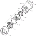
Fig. 2 is a diagram showing the overall configuration of the electric power steering apparatus according to the present embodiment, fig. 3 is a diagram showing the components of the electric power steering apparatus shown in fig. 2 exploded and viewed obliquely, and fig. 4 to 9 are diagrams showing a state in which the components are assembled in accordance with the order of assembly of the components. Therefore, in the following description, the description is given with reference to the drawings as appropriate.
As shown in fig. 2, the electric motor portion 8 constituting the electric power steering apparatus includes a motor case 11 having a cylindrical portion made of an aluminum-based metal such as aluminum or an aluminum alloy, and an electric motor, not shown, accommodated in the motor case 11, and the electronic control portion 9 includes a metal cover 12 and an electronic control assembly, not shown, accommodated in the metal cover 12, and the metal cover 12 is disposed at a position opposite to the output shaft in the axial direction of the motor case 11, and is made of an aluminum-based metal such as aluminum or an aluminum alloy, or an iron-based metal.
The motor housing 11 and the metal cover 12 are integrally fixed by press-fixing at fixing area portions formed in the outer peripheral direction of their opposite end faces. The electronic control assembly housed inside the metal cover 12 is configured by a power supply circuit unit that generates necessary power supply, a power conversion circuit unit that has a power switching element made of MOSFET, IGBT, or the like that controls driving of the electric motor unit 8, and a control circuit unit that controls the power switching element, and an output terminal of the power switching element and a coil input terminal of the electric motor are electrically connected via a bus bar.
The connector terminal assembly 13 is exposed from a hole formed in the metal cover 12 at an end surface of the metal cover 12 opposite to the motor housing 11. The connector terminal assembly 13 is fixed to a fixing portion formed in the motor housing 11 by a fixing screw. The connector terminal assembly 13 includes a connector terminal forming portion 13A for power supply, a connector terminal forming portion 13B for a detection sensor, and a connector terminal forming portion 13C for transmitting a control state to an external device.
The electronic control assembly housed in the metal cover 12 is supplied with power from a power source via a connector terminal forming portion 13A for power supply made of synthetic resin, and is supplied with a detection signal of an operation state or the like from a detection sensor via a connector terminal forming portion 13B for detection sensor, and a control state signal of the current electric power steering apparatus is sent via a connector terminal forming portion 13C for sending a control state.
Fig. 3 is an exploded perspective view of the electric power steering apparatus 6. An annular iron side yoke (not shown) is fitted into the motor housing 11, and an electric motor (not shown) is accommodated in the side yoke. The output portion 14 of the electric motor applies a steering assist force to the rack via the gear. Since the specific configuration of the electric motor is well known, the description thereof is omitted here.
The motor case 11 is made of an aluminum alloy, and functions as a heat radiating member for radiating heat generated by the electric motor and heat generated by a power supply circuit unit and a power conversion circuit unit, which will be described later, to the outside atmosphere. The electric motor 8 is constituted by an electric motor and a motor case 11.
An electronic control unit EC is mounted on an end surface portion 15 of the motor case 11 on the opposite side of the output portion 14 of the electric motor unit 8. The electronic control unit EC is composed of a power conversion circuit unit 16, a power supply circuit unit 17, a control circuit unit 18, and a connector terminal assembly 13. The end surface portion 15 of the motor housing 11 may be formed integrally with the motor housing 11, or only the end surface portion 15 may be formed separately and integrated with the motor housing 11 by screws or welding.
Here, the power conversion circuit unit 16, the power supply circuit unit 17, and the control circuit unit 18 constitute a redundant system, and constitute a dual system of the main electronic control unit and the sub electronic control unit. The main electronic control unit normally controls and drives the electric motor, but when an abnormality or a failure occurs in the main electronic control unit, the sub-electronic control unit is switched to control and drive the electric motor.
Therefore, as described later, heat from the main electronic control unit is generally transmitted to the motor case 11, and when an abnormality or a failure occurs in the main electronic control unit, the main electronic control unit is stopped and the sub-electronic control unit is operated, and heat from the sub-electronic control unit is transmitted to the motor case 11.
However, although not adopted in the present embodiment, the main electronic control unit and the sub-electronic control unit may be integrated to function as a normal electronic control unit, and when an abnormality or a failure occurs in one electronic control unit, the other electronic control unit may control and drive the electric motor with half the capacity. In this case, although the capacity of the electric motor becomes half, a so-called "power steering function" is ensured. Therefore, in a normal case, the heat of the main electronic control unit and the sub electronic control unit is transmitted to the motor housing 11.
The electronic control unit EC is composed of the power conversion circuit unit 16, the power supply circuit unit 17, the control circuit unit 18, and the connector terminal assembly 13, and is arranged in the order of the power conversion circuit unit 16, the power supply circuit unit 17, the control circuit unit 18, and the connector terminal assembly 13 in a direction away from the end surface unit 15 side. The control circuit unit 18 generates a control signal for driving the switching element of the power conversion circuit unit 16, and is configured by a microcomputer, a peripheral circuit, and the like. The power supply circuit unit 17 generates a power supply for driving the control circuit unit 18 and a power supply for the power conversion circuit unit 16, and is configured by a capacitor, a coil, a switching element, and the like. The power conversion circuit unit 16 adjusts power flowing to the coils of the electric motor, and is configured by switching elements constituting the upper and lower arms of three phases.
The main components of the electronic control unit EC, which generate a large amount of heat, are the power conversion circuit unit 16 and the power supply circuit unit 17, and the heat of the power conversion circuit unit 16 and the power supply circuit unit 17 is radiated from the motor case 11 made of an aluminum alloy. This detailed configuration will be described below with reference to fig. 4 to 9.
A connector terminal assembly 13 made of synthetic resin is provided between the control circuit unit 18 and the metal cover 12, and the connector terminal assembly 13 is connected to a vehicle battery (power supply) and another external control device (not shown). Needless to say, the connector terminal assembly 13 is connected to the power conversion circuit unit 16, the power supply circuit unit 17, and the control circuit unit 18.
The metal cover 12 has a function of housing the power conversion circuit portion 16, the power supply circuit portion 17, and the control circuit portion 18 and sealing them in a liquid-tight manner, and is fixed to the motor case 11 by being pressed and fixed in the present embodiment.
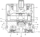
Next, the structure and the assembly method of each component will be described with reference to fig. 4 to 9. First, fig. 4 shows an external appearance of the motor housing 11, and fig. 5 shows an axial cross section of the motor housing 11.
In fig. 4 and 5, the motor case 11 is formed in a cylindrical shape and includes a side peripheral surface portion 11A, an end surface portion 15 that closes one end of the side peripheral surface portion 11A, and an end surface portion 19 that closes the other end of the side peripheral surface portion 11A. In the present embodiment, the motor case 11 is a bottomed cylindrical shape, and the side peripheral surface portion 11A and the end surface portion 15 are integrally formed. The end surface portion 19 also functions as a cover that closes the other end of the side peripheral surface portion 11A after the electric motor is housed in the side peripheral surface portion 11A.
A motor case-side annular groove portion 35 is provided on the entire circumferential surface of the end surface portion 15, and the motor case-side annular groove portion 35 has an annular groove that opens radially outward. Note that the motor housing-side annular groove portion 35 is a feature of the present embodiment, and in this regard, a detailed description will be given using fig. 10 to 12, and therefore, a further description will be omitted here.
An opening end (hereinafter, referred to as a metal cover side annular tip end portion) 37 of the metal cover 12 shown in fig. 9 is disposed to face the motor case side annular groove portion 35. The portion between the motor case-side annular groove portion 35 and the metal cover-side annular tip portion 37 of the metal cover 12 is joined liquid-tightly by a so-called liquid sealant.
As shown in fig. 5, a stator 21 having a coil 20 wound around a core is fitted into the side peripheral surface portion 11A of the motor case 11, and a rotor 22 having a permanent magnet embedded therein is rotatably housed in the stator 21. A rotation shaft 23 is fixed to the rotor 22, and one end is the output unit 14 and the other end is a rotation detection unit 24 for detecting a rotation phase and a rotation speed of the rotation shaft 23. The rotation detecting portion 24 is provided with a permanent magnet that protrudes to the outside through a through hole 25 provided in the end surface portion 15. The rotational phase and the number of rotations of the rotating shaft 23 are detected by a magnetic induction portion formed of a GMR element or the like, not shown.
Returning to fig. 4, heat dissipation regions 15A and 15B of the power conversion circuit unit 16 (see fig. 3) and the power supply circuit unit 17 (see fig. 3) are formed on the surface of the end surface portion 15 located on the opposite side of the output portion 14 of the rotation shaft 23. The board/connector fixing projections 26 are integrally erected at four corners of the end surface portion 15, and screw holes are formed therein.
The board/connector fixing projection 26 is provided for fixing a board of the control circuit unit 18 to be described later and the connector terminal assembly 13. A board receiving portion 27 having the same height in the axial direction as that of a power supply heat dissipation region 15B is formed in a board/connector fixing projection 26 that stands from a power conversion heat dissipation region 15A described later, and a screw hole is formed in the board receiving portion 27. The substrate receiving portion 27 is used for placing and fixing a glass epoxy substrate 31 of a power circuit portion 17 described later.
A radial planar area forming the end surface portion 15 orthogonal to the rotation axis 23 is divided into two. One of the heat dissipating areas is a power conversion heat dissipating area 15A to which a power conversion circuit portion 16 including power switching elements such as MOSFETs is mounted, and the other is a power source heat dissipating area 15B to which a power source circuit portion 17 is mounted. In the present embodiment, the power conversion heat dissipation region 15A is formed to have a larger area than the power supply heat dissipation region 15B. This is because, since the dual system is adopted as described above, it is necessary to secure an installation area of the power conversion circuit section 16.
The power conversion heat dissipation region 15A and the power supply heat dissipation region 15B have steps with different heights in the axial direction (the direction in which the rotary shaft 23 extends). That is, the power supply heat radiation region 15B is formed to have a step in a direction away from the power conversion heat radiation region 15A as viewed in the direction of the rotation shaft 23 of the electric motor. The step is set to a length at which the power conversion circuit unit 16 and the power supply circuit unit 17 do not interfere with each other when the power conversion circuit unit 16 is provided and then the power supply circuit unit 17 is provided.
Three elongated rectangular protruding heat dissipation portions 28 are formed in the power conversion heat dissipation region 15A. The projecting heat dissipation portion 28 is provided with a power conversion circuit portion 16 of a dual system described later. The projecting heat dissipation portion 28 projects and extends in a direction away from the electric motor when viewed in the direction of the rotation shaft 23 of the electric motor.
The power supply heat dissipation region 15B is planar and is provided with a power supply circuit unit 17 described later. Therefore, the protruding heat dissipation portion 28 functions as a heat dissipation portion that transfers heat generated by the power conversion circuit portion 16 to the end surface portion 15, and the power supply heat dissipation region 15B functions as a heat dissipation portion that transfers heat generated by the power supply circuit portion 17 to the end surface portion 15.
In this case, the heat dissipation region 15A for power conversion functions as a heat dissipation portion for transferring heat generated by the power conversion circuit portion 16 to the end surface portion 15. However, in the present embodiment, the metal substrate of the power conversion circuit portion 16 is welded to the protruding heat dissipation portion 28 by friction stir welding, thereby achieving reliable fixation.
As described above, the end surface portion 15 of the motor housing 11 of the present embodiment can be shortened in the axial direction without a heat radiating member. Further, since the motor case 11 has sufficient heat capacity, the heat of the power supply circuit unit 17 and the power conversion circuit unit 16 can be efficiently released to the outside.
Next, fig. 6 shows a state in which the power conversion circuit portion 16 is provided in the heat dissipation portion 28 (see fig. 4). As shown in fig. 6, the power conversion circuit unit 16 having a dual system is provided above the protruding heat dissipation portion 28 (see fig. 4) formed in the power conversion heat dissipation region 15A. The switching elements constituting the power conversion circuit unit 16 are placed on a metal substrate (here, aluminum-based metal is used) and thus heat dissipation is facilitated. The metal substrate is welded to the protruding heat dissipation portion 28 by friction stir welding.
Therefore, the metal substrate is firmly fixed to the heat dissipation portion 28 (see fig. 4), and the heat generated by the switching elements can be efficiently transmitted to the heat dissipation portion 28 (see fig. 4). The heat transferred to the protruding heat dissipation portion 28 (see fig. 4) is diffused into the power conversion heat dissipation region 15A, and further transferred to the side peripheral surface portion 11A of the motor housing 11 to be dissipated to the outside. Here, as described above, the height of the power conversion circuit portion 16 in the axial direction is lower than the height of the power supply heat dissipation region 15B, and therefore does not interfere with the power supply circuit portion 17 described later.
In this way, the power conversion circuit portion 16 is provided above the protruding heat dissipation portion 28 formed in the power conversion heat dissipation region 15A. Therefore, heat generated by the switching elements of the power conversion circuit unit 16 can be efficiently transferred to the heat dissipation portion 28. The heat transferred to the protruding heat dissipation portion 28 is diffused to the power conversion heat dissipation region 15A, transferred to the side peripheral surface portion 11A of the motor housing 11, and dissipated to the outside.
Next, fig. 7 shows a state in which the power supply circuit unit 17 is provided from above the power conversion circuit unit 16. As shown in fig. 7, a power circuit portion 17 is provided above the power heat dissipation region 15B. The capacitor 29, the coil 30, and the like constituting the power supply circuit unit 17 are placed on a glass epoxy substrate 31. The power supply circuit 17 also adopts a dual system, and as can be seen from the figure, power supply circuits each composed of a capacitor 29, a coil 30, and the like are symmetrically formed. Electric elements such as capacitors, other than switching elements, of the power conversion circuit portion 16 are placed on the glass epoxy substrate 31.
The surface of the glass epoxy substrate 31 on the side of the power supply heat dissipation region 15B (see fig. 6) is fixed to the end surface portion 15 so as to be in contact with the power supply heat dissipation region 15B. As shown in fig. 7, the fixing method is to fix the fixing member to a screw hole provided in the board receiving portion 27 of the board/connector fixing protrusion 26 with a fixing screw not shown. The fixing screws (not shown) are also fixed to screw holes provided in the power supply heat dissipation region 15B (see fig. 6).
Since the power supply circuit portion 17 is formed by the glass epoxy substrate 31, double-sided mounting is possible. A rotation phase and rotation speed detecting unit including a GMR element, a detection circuit thereof, and the like, which are not shown, is mounted on the surface of the glass epoxy substrate 31 on the side of the power supply heat dissipation region 15B (see fig. 6), and the rotation phase and rotation speed of the rotation are detected in cooperation with the rotation detecting unit 24 (see fig. 5) provided on the rotation shaft 23 (see fig. 5).
In this way, since the glass epoxy substrate 31 is fixed in contact with the power supply heat dissipation region 15B (see fig. 6), the heat generated by the power circuit portion 17 can be efficiently transferred to the power supply heat dissipation region 15B (see fig. 6). The heat transferred to the power supply heat dissipation region 15B (see fig. 6) is diffused and transferred to the side peripheral surface portion 11A of the motor housing 11, and is released to the outside. Here, the heat transfer performance can be further improved by interposing any one of an adhesive, heat-dissipating grease, and heat sink having excellent heat transfer properties between the glass epoxy substrate 31 and the power supply heat dissipation region 15B (see fig. 6).
In this way, the power circuit portion 17 is provided above the power heat dissipation region 15B. The surface of the glass epoxy substrate 31 on which the circuit elements of the power circuit portion 17 are placed on the power heat dissipation region 15B side is fixed to the end surface portion 15 so as to be in contact with the power heat dissipation region 15B. Therefore, the heat generated by the power circuit unit 17 can be efficiently transferred to the power heat dissipation region 15B. The heat transferred to the power supply heat dissipation region 15B is diffused and transferred to the side peripheral surface portion 11A of the motor housing 11 and is released to the outside.
Next, fig. 8 shows a state in which the control circuit unit 18 is provided from above the power circuit unit 17. As shown in fig. 8, a control circuit unit 18 is provided above the power circuit unit 17. The microcomputer 32 and the peripheral circuit 33 constituting the control circuit unit 18 are mounted on a glass epoxy substrate 34. The control circuit unit 18 also adopts a dual system, and as can be seen from the figure, control circuits each composed of a microcomputer 32 and a peripheral circuit 33 are formed symmetrically. The microcomputer 32 and the peripheral circuit 33 may be provided on the surface of the glass epoxy substrate 34 on the power supply circuit portion 17 side.
As shown in fig. 8, the glass epoxy substrate 34 is fixed to a screw hole provided at the top of the substrate/connector fixing protrusion 26 (see fig. 7) by a fixing screw (not shown) so as to be sandwiched by the connector terminal assembly 13, and a space for disposing the capacitor 29, the coil 30, and the like of the power supply circuit 17 shown in fig. 7 is formed between the glass epoxy substrate 31 of the power supply circuit 17 (see fig. 7) and the glass epoxy substrate 34 of the control circuit 18.
Next, fig. 9 shows a state where the connector terminal assembly 13 is installed from above the control circuit unit 18. As shown in fig. 9, a connector terminal assembly 13 is provided above the control circuit unit 18. The connector terminal assembly 13 is fixed to a screw hole provided in the top of the board/connector fixing projection 26 by a fixing screw 36 so as to sandwich the control circuit unit 18. In this state, as shown in fig. 3, the connector terminal assembly 13 is connected to the power conversion circuit unit 16, the power supply circuit unit 17, and the control circuit unit 18.
Then, the metal cover side annular tip portion 37 of the metal cover 12 is arranged to cover the motor housing side annular groove portion 35 of the motor housing 11 from the outside, and is fixed by a press fixing portion provided along the outer circumferential direction of the metal cover 12.
As shown in fig. 10, the press-fixing portions 38 are formed at intervals of substantially 120 ° around the axis of the rotary shaft 23 on the outer periphery of the metal cover 12. Fig. 10 shows the external appearance of the electric power steering apparatus 6 in a state where the motor case 11 and the metal cover 12 are fixed by being pressed and fixed. Fig. 11 is a cross-section of the metal cover 12 before it is fixed to the end surface portion 15 of the motor case 11.
In fig. 10 and 11, a plurality of (three) hold-down fixing portions 38 are formed on the outer peripheral surface of the metal cover 12. The press fixing portion 38 is formed by pressing the wall surface of the metal cover 12 with a pressing tool against a press recess 40 formed of a press groove, a press hole, or the like provided in a fixing wall 39, and the fixing wall 39 extends in the axial direction from the motor housing-side annular groove portion 35 formed over the entire circumferential surface of the end surface portion 15 of the motor housing 11 toward the connector terminal assembly 13 side, and forms a power conversion heat dissipation region 15A and a power supply heat dissipation region 15B. The axial positioning of the metal cover 12 is performed by the connector terminal assembly 13, and the wall surface of the metal cover 12 is pressed and pressed against the pressing recess 40 by a pressing tool in a state where the axial position of the metal cover 12 is determined.
The liquid sealant 41 for liquid tightness is filled into the space formed by the motor case side annular groove portion 35 where the cover metal side annular tip portion 37 of the cover metal 12 is disposed without a gap. Therefore, a liquid-tight seal region is formed between the hold-down fixing portion 38 and the metal cover-side annular tip portion 37 of the metal cover 12, and therefore, the intrusion of the saline or the like into the seal region is prevented. Therefore, since salt water or the like cannot enter the hold-down fixing portion 38, corrosion of the hold-down fixing portion 38 can be suppressed, and mechanical reliability can be improved. Furthermore, the intrusion of salt water or the like into the electronic control unit 9 can be suppressed, and the electrical reliability can be improved together.
Next, a more detailed structure in the vicinity of the joint region between the metal cover side annular tip portion 37 and the motor case side annular groove portion 35 according to the first embodiment of the present invention will be described with reference to fig. 12 and 13.
In fig. 12, the outer peripheral diameter Dc of the foremost end of the metal cover-side annular front end portion 37 of the metal cover 12 and the outer peripheral diameter Dh of the end surface portion 15 of the motor case 11 are substantially the same radius, and the outer peripheral surfaces thereof are formed on the same surface (one surface) in appearance. The motor housing-side annular groove portion 35 formed in the outer peripheral surface of the end surface portion 15 of the motor housing 11 is formed so as to recede inward by a predetermined distance L (recessed inward) from the fixed wall 39 in a radial direction orthogonal to the axis of the rotating shaft 23 (see fig. 11), that is, the same axis of the motor housing 11.
On the other hand, the metal cover side annular tip portion 37 of the metal cover 12 is bent so that the opening surface is expanded outward, and an annular inclined surface 37IN which the opening surface is inclined outward IN the radial direction of the metal cover 12 is formed on the inner circumferential surface of the metal cover side annular tip portion 37. The bending start point 37S of the annular inclined surface 37IN is bent and expanded from the vicinity of the upper wall surface 35U IN the drawing of the motor case-side annular groove portion 35.
As shown in fig. 11, the liquid sealant 41 is applied so as to fill the motor case side annular groove portion 35 before the metal cover 12 is attached. Here, as described above, the liquid sealant 41 has adhesiveness and viscosity, and when the metal cover side annular tip portion 37 is pressed IN the direction of the end surface portion 15 of the motor housing 11, a pulling force acts on the liquid sealant 41 that is IN contact with the annular inclined surface 37IN that is the inner peripheral surface of the metal cover side annular tip portion 37. Therefore, the liquid sealant 41 filled IN the motor case side annular groove portion 35 moves so as to be pulled along the movement of the annular inclined surface 37IN of the metal cover side annular tip portion 37.
However, IN the present embodiment, the annular inclined surface 37IN that expands obliquely outward IN the radial direction of the metal cover 12 is formed on the inner peripheral surface of the metal cover side annular tip portion 37, and thus the pulling force generated by contact with the liquid sealant 41 is dispersed at least IN the direction along the annular inclined surface 37IN, the pressing direction of the metal cover 12, and the radial direction as indicated by arrows. Therefore, even if the liquid sealant 41 is pulled along the movement of the annular inclined surface 37IN of the metal-cover-side annular tip portion 37, the load is dispersed, and therefore, the space generated by the movement of the liquid sealant 41 can be suppressed.
IN this way, when the metal cover side annular tip portion 37 is pressed toward the end surface portion 15 of the motor housing 11, the liquid sealant 41 filled IN the motor housing side annular groove portion 35 is prevented from moving so as to be pulled along the movement of the annular inclined surface 37IN of the metal cover side annular tip portion 37. This makes it difficult to create a space in the motor case side annular groove portion 35 where the liquid sealant 41 does not exist, and the seal length is increased, whereby the possibility of salt water or the like entering the metal cover 12 can be suppressed, and as a result, the mechanical and electrical reliability can be improved.
Here, as shown IN fig. 13, the inclination angle θ of the annular inclined surface 37IN of the metal cover-side annular tip portion 37 of the metal cover 12 of the present embodiment is preferably set to be IN the range of 5 ° to 9 °, so that the liquid sealant 41 can be sufficiently left.
The length of the motor case side annular groove portion 35 IN the axial direction is used to measure the degree of contact between the liquid sealant 41 and the annular inclined surface 37IN of the metal cover side annular tip portion 37. In this case, the metal cover 12 is divided into eight parts at equal intervals in the circumferential direction, and the ratio of the bonding length (bonding length/axial length of the motor case side annular groove portion 35) at each part is obtained and averaged.
IN the conventional structure shown IN fig. 16, the ratio of the bonding length is about 43%, and the inclination angle θ of the annular inclined surface 37IN is about 81% IN the case of 5 °, about 89% IN the case of 7 °, and about 92% IN the case of 9 °. Therefore, from the viewpoint of leaving some margin, it is considered sufficient that the inclination angle θ of the annular inclined surface 37IN is determined to be IN the range of 4 ° to 12 °.
Since the annular inclined surface 37IN of the metal cover side annular tip portion can sufficiently secure the sealing length by the liquid sealant 41 as described above, the outer peripheral diameter Dc of the foremost end of the metal cover side annular tip portion 37 of the metal cover 12 and the outer peripheral diameter Dh of the end surface portion 15 of the motor housing 11 can be set to substantially the same radius, and the diameter increase of the electric drive device can be avoided.
Example 2
As shown IN fig. 12, the radial wall surface 35B-1 of the motor housing-side annular groove portion 35 is formed along the axis of the motor housing 11, but may be formed along the inclined wall surface 35B-2 of the annular inclined surface 37IN of the metal cover-side annular tip portion 37 as shown IN fig. 14. This can provide an effect of reducing the filling amount of the liquid sealant 41.
Example 3
IN the embodiment shown IN fig. 12, the metal cover side annular tip portion 37 of the metal cover 12 is bent outward to expand to form an annular inclined surface 37 IN. IN contrast, IN fig. 15, the annular inclined surface 37IN is not formed by bending, but the metal cover side annular tip end portion 42 of the metal cover 12 is formed along the axis of the motor housing 11, and the annular inclined surface 42IN is formed only on the inner peripheral surface. The annular inclined surface 42IN may be formed by press working or cutting.
With this structure, as described above, it is possible to suppress the phenomenon that the liquid sealant 41 filled IN the motor case side annular groove portion 35 moves so as to be pulled along the movement of the annular inclined surface 42IN of the metal cover side annular leading end portion 42 when the metal cover side annular leading end portion 37 is pressed toward the end surface portion 15 side of the motor case 11. This makes it difficult to create a space in the motor case side annular groove portion 35 where the liquid sealant 41 does not exist, and the seal length is increased, whereby the possibility of salt water or the like entering the metal cover 12 can be suppressed, and as a result, the mechanical and electrical reliability can be improved.
In the above embodiments, the liquid sealant 41 for liquid-tight use is made of an adhesive synthetic resin, and in the present embodiment, a silicone rubber-based elastic adhesive is used. The silicone rubber-based elastic adhesive has a property of absorbing stress such as external vibration or impact and making it difficult to concentrate the stress on the adhesive interface. Therefore, in a device such as an electric power steering device in which vibration, impact, or the like acts, there is a possibility that the adhesive interface peels off and loses the liquid-tight function, but the use of a silicone rubber-based elastic adhesive can reduce the possibility that the liquid-tight function is lost. In the present embodiment, since the sealing is performed by the liquid sealant 41 having adhesiveness, a conventionally used liquid-tight O-ring can be omitted. Therefore, it is not necessary to form a housing groove for housing the O-ring in the fixing wall 39, and the increase in manufacturing cost can be suppressed.
The silicone elastic adhesive (liquid sealant 41) may be a liquid gasket (FIPG: FORMED IN PLACE GASKET, in-place gasket) having an adhesive function, or a liquid gasket made of a material that is cured at normal temperature or by heating.
Further, since the metal cover 12 and the motor housing 11 are fixed by the press fixing portion 38 without using a fixing screw, the external shape can be reduced and the weight can be reduced. Further, although it is necessary to form a housing groove for housing the O-ring when the O-ring is used, in the present embodiment, the O-ring is not used, and therefore, processing such as the housing groove is not necessary, and an increase in manufacturing cost can be suppressed.
By mixing the liquid sealant 41 with a material having excellent thermal conductivity such as alumina, the liquid sealant 41 having high heat dissipation properties can have a large bonding area, and the heat of the power conversion heat dissipation region 15A and the power supply heat dissipation region 15B can be efficiently dissipated to the metal cover 12. This enables heat from the electric components constituting the power supply circuit unit and the power conversion circuit unit to be efficiently dissipated to the outside, thereby achieving a reduction in size.
In the above embodiment, the three compression fixing portions 38 are formed as fixing means for fixing the metal cover 12 and the motor housing 11 without using fixing screws, but the compression fixing portions may be formed over the entire circumference.
As described above, according to the present invention, the following structure is formed: the motor case side annular groove portion is formed on an outer peripheral surface of an end surface portion of the metal motor case on the opposite side of an output portion of a rotating shaft of the electric motor, and is constituted by an annular groove retreating inward in a radial direction orthogonal to an axis of the motor case, the metal cover side annular front end portion is formed at an opening end of a metal cover covering an electronic control portion for controlling the electric motor, and is opposed to the annular groove of the motor housing side annular groove portion from the outside, a liquid sealant is filled between the motor case side annular groove portion and the metal cover side annular tip portion in a state where the metal cover side annular tip portion is disposed to face the motor case side annular groove portion, an annular inclined surface that is inclined outward in the radial direction of the metal cover is formed on the inner peripheral surface of the metal cover side annular tip portion.
Accordingly, since the annular inclined surface which is inclined outward in the radial direction of the metal cover is formed on the inner peripheral surface of the metal cover-side annular tip portion, when the metal cover-side annular tip portion is pressed against the end surface side of the motor housing, the pressing force acting on the liquid sealant filled in the motor housing-side annular groove portion is dispersed, whereby the movement of the liquid sealant along the inner peripheral surface of the metal cover-side annular tip portion is suppressed by pulling, and the generation of a space in which the liquid sealant does not exist can be suppressed.
The present invention is not limited to the above-described embodiments, and various modifications are also included. For example, the above embodiments are described in detail to facilitate understanding of the present invention, but the present invention is not limited to having all the structures described. Further, a part of the structure of one embodiment may be replaced with the structure of another embodiment, and the structure of another embodiment may be added to the structure of one embodiment. Further, some of the configurations of the embodiments may be added, deleted, or replaced with other configurations.
As the electric drive device according to the embodiment described above, for example, the following configuration is considered.
That is, the electric drive device includes, in one aspect thereof: a motor case that houses an electric motor that drives a machine control element; an electronic control unit disposed on an end surface side of the motor case opposite to an output unit of a rotation shaft of the electric motor, for driving the electric motor; a cover that covers the electronic control unit; wherein the electric drive device comprises: a motor case side annular groove portion formed in an outer peripheral surface of the end surface portion of the motor case on an opposite side to the output portion of the rotary shaft of the electric motor, and including an annular groove receding inward in a radial direction orthogonal to an axis of the motor case; a cover-side annular front end portion formed at an opening end of the cover covering the electronic control unit for controlling the electric motor, the cover-side annular front end portion facing the annular groove of the motor-case-side annular groove portion from outside; in a state where the cover-side annular leading end portion is disposed to face the motor-housing-side annular groove portion, a liquid sealant is filled between the motor-housing-side annular groove portion and the cover-side annular leading end portion, and an annular inclined surface that expands obliquely outward in a radial direction of the cover is formed on an inner peripheral surface of the cover-side annular leading end portion.
In a preferred aspect of the electric drive device, the cover-side annular tip end portion of the cover is formed with the annular inclined surface by bending.
In another preferred embodiment, in any one of the electric drive devices, the cover-side annular tip portion of the cover is formed with the annular inclined surface by press working or cutting working.
In still another preferred aspect of the electric drive device, a radial wall surface of the motor housing-side annular groove portion is formed along an axis of the motor housing.
In still another preferred aspect of the electric drive device, a radial wall surface of the motor case-side annular groove portion is formed along the annular inclined surface of the cover-side annular tip portion.
As the electric power steering apparatus according to the above embodiment, for example, the following configuration is considered.
That is, the electric power steering apparatus includes, in one aspect thereof: an electric motor that applies a steering assist force to a steering shaft based on an output from a torque sensor that detects a turning direction and a turning torque of the steering shaft; a motor case that houses the electric motor; an electronic control unit disposed on an end surface side of the motor case opposite to an output unit of a rotation shaft of the electric motor, for driving the electric motor; a cover that covers the electronic control unit; wherein the electric power steering device includes: a motor case side annular groove portion formed in an outer peripheral surface of the end surface portion of the motor case on an opposite side to the output portion of the rotary shaft of the electric motor, and including an annular groove receding inward in a radial direction orthogonal to an axis of the motor case; a cover-side annular front end portion formed at an opening end of the cover covering the electronic control unit for controlling the electric motor, the cover-side annular front end portion facing the annular groove of the motor-case-side annular groove portion from outside; in a state where the cover-side annular leading end portion is disposed to face the motor housing-side annular groove portion, a liquid sealant is filled between the motor housing-side annular groove portion and the cover-side annular leading end portion, and an annular inclined surface of the cover-side annular leading end portion, which is inclined outward in a radial direction of the cover, is formed on an inner peripheral surface of the cover-side annular leading end portion.
In a preferred aspect of the electric power steering apparatus, the cover-side annular tip end portion of the cover is formed with the annular inclined surface by bending.
In another preferred aspect of the electric power steering apparatus of any one of the above aspects, the cover-side annular tip end portion of the cover is formed with the annular inclined surface by press working or cutting working.
In still another preferred aspect of the electric power steering apparatus, a radial wall surface of the motor housing-side annular groove portion is formed along an axis of the motor housing.
In still another preferred aspect of the electric power steering apparatus, a radial wall surface of the motor case-side annular groove portion is formed along the annular inclined surface of the cover-side annular tip portion.