CN111656743A - Hybrid multilayer signal decomposition system and method - Google Patents
Hybrid multilayer signal decomposition system and method Download PDFInfo
- Publication number
- CN111656743A CN111656743A CN201980008311.3A CN201980008311A CN111656743A CN 111656743 A CN111656743 A CN 111656743A CN 201980008311 A CN201980008311 A CN 201980008311A CN 111656743 A CN111656743 A CN 111656743A
- Authority
- CN
- China
- Prior art keywords
- signal
- decomposed
- signals
- decomposition
- constant envelope
- Prior art date
- Legal status (The legal status is an assumption and is not a legal conclusion. Google has not performed a legal analysis and makes no representation as to the accuracy of the status listed.)
- Granted
Links
Images


Classifications
-
- H—ELECTRICITY
- H04—ELECTRIC COMMUNICATION TECHNIQUE
- H04L—TRANSMISSION OF DIGITAL INFORMATION, e.g. TELEGRAPHIC COMMUNICATION
- H04L27/00—Modulated-carrier systems
- H04L27/26—Systems using multi-frequency codes
- H04L27/2601—Multicarrier modulation systems
- H04L27/2614—Peak power aspects
-
- H—ELECTRICITY
- H04—ELECTRIC COMMUNICATION TECHNIQUE
- H04B—TRANSMISSION
- H04B1/00—Details of transmission systems, not covered by a single one of groups H04B3/00 - H04B13/00; Details of transmission systems not characterised by the medium used for transmission
- H04B1/69—Spread spectrum techniques
- H04B1/707—Spread spectrum techniques using direct sequence modulation
- H04B1/7097—Interference-related aspects
- H04B1/7103—Interference-related aspects the interference being multiple access interference
- H04B1/7105—Joint detection techniques, e.g. linear detectors
- H04B1/71052—Joint detection techniques, e.g. linear detectors using decorrelation matrix
-
- H—ELECTRICITY
- H04—ELECTRIC COMMUNICATION TECHNIQUE
- H04J—MULTIPLEX COMMUNICATION
- H04J13/00—Code division multiplex systems
- H04J13/0007—Code type
-
- H—ELECTRICITY
- H04—ELECTRIC COMMUNICATION TECHNIQUE
- H04L—TRANSMISSION OF DIGITAL INFORMATION, e.g. TELEGRAPHIC COMMUNICATION
- H04L27/00—Modulated-carrier systems
- H04L27/32—Carrier systems characterised by combinations of two or more of the types covered by groups H04L27/02, H04L27/10, H04L27/18 or H04L27/26
- H04L27/34—Amplitude- and phase-modulated carrier systems, e.g. quadrature-amplitude modulated carrier systems
- H04L27/3405—Modifications of the signal space to increase the efficiency of transmission, e.g. reduction of the bit error rate, bandwidth, or average power
- H04L27/3411—Modifications of the signal space to increase the efficiency of transmission, e.g. reduction of the bit error rate, bandwidth, or average power reducing the peak to average power ratio or the mean power of the constellation; Arrangements for increasing the shape gain of a signal set
-
- H—ELECTRICITY
- H04—ELECTRIC COMMUNICATION TECHNIQUE
- H04L—TRANSMISSION OF DIGITAL INFORMATION, e.g. TELEGRAPHIC COMMUNICATION
- H04L27/00—Modulated-carrier systems
- H04L27/32—Carrier systems characterised by combinations of two or more of the types covered by groups H04L27/02, H04L27/10, H04L27/18 or H04L27/26
- H04L27/34—Amplitude- and phase-modulated carrier systems, e.g. quadrature-amplitude modulated carrier systems
- H04L27/3488—Multiresolution systems
-
- H—ELECTRICITY
- H04—ELECTRIC COMMUNICATION TECHNIQUE
- H04B—TRANSMISSION
- H04B2201/00—Indexing scheme relating to details of transmission systems not covered by a single group of H04B3/00 - H04B13/00
- H04B2201/69—Orthogonal indexing scheme relating to spread spectrum techniques in general
- H04B2201/707—Orthogonal indexing scheme relating to spread spectrum techniques in general relating to direct sequence modulation
- H04B2201/70706—Orthogonal indexing scheme relating to spread spectrum techniques in general relating to direct sequence modulation with means for reducing the peak-to-average power ratio
-
- H—ELECTRICITY
- H04—ELECTRIC COMMUNICATION TECHNIQUE
- H04J—MULTIPLEX COMMUNICATION
- H04J13/00—Code division multiplex systems
- H04J13/0007—Code type
- H04J2013/0037—Multilevel codes
Landscapes
- Engineering & Computer Science (AREA)
- Computer Networks & Wireless Communication (AREA)
- Signal Processing (AREA)
- Physics & Mathematics (AREA)
- Mathematical Physics (AREA)
- Digital Transmission Methods That Use Modulated Carrier Waves (AREA)
- Transmitters (AREA)
Abstract
Description
相关申请案的交叉参考Cross-references to related applications
本申请要求于2018年1月22日递交的发明名称为“混合多层信号分解系统与方法(Systems and Methods for Hybrid Multi-layer Signal Decomposition)”的美国专利申请案第15/876,950号的优先权,其内容以引用的方式并入本文中。This application claims priority to US Patent Application Serial No. 15/876,950, filed January 22, 2018, entitled "Systems and Methods for Hybrid Multi-layer Signal Decomposition" , the contents of which are incorporated herein by reference.
技术领域technical field
示例性实施例通常涉及通信和信号处理技术领域,尤其涉及信号分解的方法和系统。Exemplary embodiments relate generally to the technical fields of communications and signal processing, and more particularly to methods and systems for signal decomposition.
背景技术Background technique
信号分解通常是指将一个源信号转换成多个分解信号,这些分解信号共同表示原始源信号。例如,多个分解信号可以包含源信号的有用个别信息,可以单独处理,或者可以重组为原始源信号。Signal decomposition generally refers to converting a source signal into multiple decomposed signals, which together represent the original source signal. For example, multiple decomposed signals may contain useful individual information of the source signal, may be processed separately, or may be recombined into the original source signal.
当前提出的第五代(5th Generation,5G)通信标准等最新无线标准旨在改进通信,例如,以实现更大的容量。实现5G系统的某些方面可能产生具有高峰均功率比(Peak-Average Power Ratio,PAPR)波形的高动态信号振幅。较高PAPR的信号条件通常需要较多比特来表示信号,这也可以称为比特分辨率或比特量化。较高PAPR的信号条件通常会降低功率效率,这是我们一般不希望的。较高PAPR的信号条件可能超出某些子系统的有效动态范围。The latest wireless standards, such as the currently proposed 5th Generation (5G) communication standard, aim to improve communication, eg, to achieve greater capacity. Implementing certain aspects of 5G systems may result in highly dynamic signal amplitudes with Peak-Average Power Ratio (PAPR) waveforms. Signal conditions of higher PAPR generally require more bits to represent the signal, which may also be referred to as bit resolution or bit quantization. Signal conditions with higher PAPR generally reduce power efficiency, which is generally undesirable. Signal conditions for higher PAPR may exceed the effective dynamic range of some subsystems.
现有的一些系统对信号进行分解,但是这些系统可能具有宽信号带宽和高PAPR。例如,一些现有信号分解系统的困难在于它们可能有带宽扩展问题。Some existing systems decompose the signal, but these systems may have wide signal bandwidth and high PAPR. For example, a difficulty with some existing signal decomposition systems is that they may have bandwidth expansion problems.
可用于信号分解系统的某些子系统的困难是它们的动态操作范围有限。A difficulty with some of the subsystems available for signal decomposition systems is their limited dynamic operating range.
希望提供将源信号分解为具有较低PAPR、较高功率效率、较少量化比特和受限带宽的分解信号的系统和方法。It is desirable to provide systems and methods for decomposing a source signal into decomposed signals with lower PAPR, higher power efficiency, fewer quantization bits, and limited bandwidth.
该背景信息提供申请人认为可能的相关信息。任何上述信息不允许或不应解释为构成现有技术。This background information provides relevant information that the applicant considers possible. Any of the above information is not permitted or should be construed as constituting prior art.
发明内容SUMMARY OF THE INVENTION
一种混合多层(多级)分解方法,可用于将源信号分解为多个分解信号,所述多个分解信号可用于共同表示所述源信号或恢复所述源信号。分解信号的峰均功率比(Peak-to-Average Power Ratio,PAPR)比源信号低,并且通常需要较少的量化比特来表示每个分解信号。所述方法的示例性实施例包括多层信号分解,以生成恒定包络信号,而不影响原始信号或对原始信号的影响最小。A hybrid multi-layer (multi-level) decomposition method that can be used to decompose a source signal into multiple decomposed signals that can be used to collectively represent the source signal or recover the source signal. The peak-to-average power ratio (PAPR) of the decomposed signal is lower than that of the source signal, and generally fewer quantization bits are required to represent each decomposed signal. Exemplary embodiments of the method include multiple layers of signal decomposition to generate a constant envelope signal with no or minimal impact on the original signal.
在示例性实施例中,所述方法包括将源信号分解为两个一级分解信号,每个一级分解信号的恒定包络幅值为源信号的最大幅值的一半。所述方法还包括:在每次迭代时根据阈值幅值将所述一级分解信号中的每个一级分解信号迭代分解为后级分解信号。每个后级分解信号具有一个或多个恒定包络,所述一个或多个恒定包络的恒定包络幅值取决于阈值幅值。各级输出的分解信号具有恒定的包络特性。In an exemplary embodiment, the method includes decomposing the source signal into two first-order decomposed signals, each of which has a constant envelope amplitude that is half the maximum amplitude of the source signal. The method further includes iteratively decomposing each of the first-level decomposed signals into subsequent-stage decomposed signals according to a threshold amplitude value at each iteration. Each post-decomposition signal has one or more constant envelopes whose constant envelope amplitudes depend on the threshold amplitude. The decomposed signals output by each stage have constant envelope characteristics.
至少一些示例性实施例的目的是提供一种用于多层信号分解的方法和系统,该方法和系统保持每一层的恒定包络特性并限制信号分解的带宽扩展。It is an object of at least some example embodiments to provide a method and system for multi-layer signal decomposition that maintains a constant envelope characteristic of each layer and limits the bandwidth extension of the signal decomposition.
至少一些示例性实施例的目的是,与其它现有分解方法相比,使用较低误差矢量幅度(error vector magnitude,EVM)的信号分解来减小PAPR。It is an object of at least some example embodiments to reduce PAPR using a lower error vector magnitude (EVM) signal decomposition than other existing decomposition methods.
至少一些示例性实施例的目的是在多层信号分解的每一层处保持恒定振幅包络,而不影响原始源信号的可恢复性或对原始源信号的可恢复性影响最小。It is an aim of at least some exemplary embodiments to maintain a constant amplitude envelope at each layer of the multi-layer signal decomposition without affecting the recoverability of the original source signal or with minimal impact on the recoverability of the original source signal.
至少一些示例性实施例的目的是限制子系统的输入振幅范围,所述子系统可以更好地处理接收到的输入信号的有限振幅范围。An object of at least some example embodiments is to limit the input amplitude range of a subsystem that can better handle the limited amplitude range of the received input signal.
一个示例性实施例是一种用于分解源信号的方法,所述方法包括:将所述源信号分解为两个一级分解信号,每个一级分解信号的恒定包络幅值为所述源信号的最大幅值的一半;将所述一级分解信号中的每个一级分解信号分解为各自具有恒定包络的第一二级分解信号和第二二级分解信号,其中,所述第一二级分解信号的恒定包络幅值等于阈值幅值,所述第二二级分解信号的恒定包络幅值等于所述一级分解信号中的一个的所述恒定包络幅值减去所述阈值幅值。An exemplary embodiment is a method for decomposing a source signal, the method comprising decomposing the source signal into two first-order decomposed signals, each first-order decomposed signal having a constant envelope amplitude of the half of the maximum amplitude of the source signal; decompose each of the first-level decomposition signals into a first two-level decomposition signal and a second two-level decomposition signal each having a constant envelope, wherein the The constant envelope amplitude of the first second-order decomposed signal is equal to the threshold amplitude, and the constant envelope amplitude of the second second-order decomposed signal is equal to the constant envelope amplitude of one of the first-order decomposed signals minus the to the threshold amplitude.
在所述方法的示例性实施例中,所述阈值幅值为预定义值。In an exemplary embodiment of the method, the threshold magnitude is a predefined value.
在上述方法中任一方法的示例性实施例中,所述阈值幅值为所述两个一级分解信号中任一个的最大幅值的一半。In an exemplary embodiment of any of the above methods, the threshold amplitude is half the maximum amplitude of either of the two first-order decomposed signals.
在上述方法中任一方法的实例实施例中,对于每个采样值k,所述源信号表示为x(k),其中所述两个一级分解信号为:In an example embodiment of any of the above methods, for each sample value k, the source signal is denoted as x(k), where the two first-order decomposed signals are:

和and

其中,Am为所述源信号的所述最大幅值,Φ(k)和(k)为k的函数,j为单位虚数。Wherein, Am is the maximum amplitude of the source signal, Φ( k ) and (k) are functions of k, and j is a unit imaginary number.
在上述方法中任一方法的示例性实施例中,所述两个一级分解信号为:In an exemplary embodiment of any one of the above methods, the two first-order decomposition signals are:

和and

其中,对于每个采样值k,所述源信号表示为x(k),e(k)为误差函数。Wherein, for each sample value k, the source signal is denoted as x(k), and e(k) is the error function.
在上述方法中任一方法的示例性实施例中,所述第一二级分解信号和所述第二二级分解信号为:In an exemplary embodiment of any of the above methods, the first two-level decomposition signal and the second two-level decomposition signal are:

和and

其中,对于每个采样值k,所述源信号表示为x(k),d为所述阈值幅值。Wherein, for each sample value k, the source signal is denoted as x(k), and d is the threshold amplitude.
在上述方法中任一方法的示例性实施例中,d是所述两个恒定一级分解信号中的一个的最大幅值的一半,其中,所述两个一级分解信号中的一个分解得到的所述第一二级分解信号和所述第二二级分解信号为:In an exemplary embodiment of any of the above methods, d is half the maximum magnitude of one of the two constant first-order decomposed signals, wherein one of the two first-order decomposed signals yields The first two-level decomposition signal and the second two-level decomposition signal are:

和and

在上述方法中任一方法的示例性实施例中,对于每个采样值k,所述源信号表示为x(k),其中,所述两个一级分解信号中的一个分解得到的所述第一二级分解信号和所述第二二级分解信号为:In an exemplary embodiment of any one of the above methods, for each sample value k, the source signal is denoted as x(k), wherein the The first two-level decomposition signal and the second two-level decomposition signal are:

和and
其中,d为阈值幅值,Am为所述源信号的所述最大幅值,Φ和为k的函数,j为单位虚数。Wherein, d is the threshold amplitude, Am is the maximum amplitude of the source signal, the sum of Φ is a function of k, and j is a unit imaginary number.
在上述方法中任一方法的示例性实施例中,所述方法还包括:迭代地对作为输入信号的所述二级分解信号中的每个二级分解信号执行至少一次后级分解,如下所示:确定本级分解的阈值幅值,将所述输入信号分解为各自具有恒定包络的第一本级分解信号和第二本级分解信号,第一输出信号的恒定包络幅值等于所述本级分解的所述阈值幅值,第二输出信号的恒定包络幅值等于所述输入信号的恒定包络幅值减去所述本级分解的所述阈值幅值。In an exemplary embodiment of any of the above methods, the method further comprises: iteratively performing at least one post-decomposition on each of the two-level decomposed signals as input signals, as follows Display: determine the threshold amplitude value of this stage decomposition, decompose the input signal into a first local stage decomposition signal and a second local stage decomposition signal each with a constant envelope, and the constant envelope amplitude of the first output signal is equal to the The threshold amplitude of the current stage decomposition, the constant envelope amplitude of the second output signal is equal to the constant envelope amplitude of the input signal minus the threshold amplitude of the current stage decomposition.
在上述方法中任一方法的示例性实施例中,所述方法还包括:确定所述输出信号中任一个的恒定包络幅值已达到预定值,并响应于所述确定,结束迭代执行。In an exemplary embodiment of any of the above methods, the method further includes determining that the constant envelope amplitude of any of the output signals has reached a predetermined value, and in response to the determination, ending the iterative execution.
在上述方法中任一方法的示例性实施例中,当所有所述输出信号的所述恒定包络幅值达到所述预定值时,所述迭代执行结束。In an exemplary embodiment of any of the above methods, the iterative execution ends when the constant envelope amplitudes of all of the output signals reach the predetermined value.
在上述方法中任一方法的示例性实施例中,所述方法还包括:确定所述迭代执行已经执行预定数量级的分解,并响应于所述确定,结束所述迭代执行。In an exemplary embodiment of any of the above methods, the method further includes determining that the iterative execution has performed a predetermined order of magnitude decomposition, and in response to the determination, ending the iterative execution.
在上述方法中任一方法的示例性实施例中,所述方法还包括:确定预定时间段已过去,并响应于所述确定,结束所述迭代执行。In an exemplary embodiment of any of the above methods, the method further includes determining that a predetermined period of time has elapsed, and in response to the determination, ending the iterative execution.
在上述方法中任一方法的示例性实施例中,每级分解的阈值幅值为所述输入信号中的一个的恒定包络振幅包络值的一半。In an exemplary embodiment of any of the above methods, the threshold amplitude of each level of decomposition is half the constant envelope amplitude envelope value of one of the input signals.
在上述方法中任一方法的示例性实施例中,每级分解的所述阈值幅值小于所述输入信号中的一个的恒定包络振幅包络值。In an exemplary embodiment of any of the above methods, the threshold amplitude value of each level of decomposition is less than a constant envelope amplitude envelope value of one of the input signals.
在上述方法中任一方法的示例性实施例中,所述方法还包括:使用至少一个滤波器对所述二级分解信号中的每个二级分解信号进行滤波。In an exemplary embodiment of any of the above methods, the method further comprises: filtering each of the two-level decomposition signals using at least one filter.
在上述方法中任一方法的示例性实施例中,所述至少一个滤波器包括至少一个低通滤波器或至少一个带通滤波器。In an exemplary embodiment of any of the above methods, the at least one filter comprises at least one low pass filter or at least one band pass filter.
在上述方法中任一方法的示例性实施例中,所述方法还包括:将所述二级分解信号中的每个二级分解信号发送到至少一个子系统,所述至少一个子系统包括功率放大器、数模转换器(Digital-To-Analog Converter,DAC)、发射器或传输线。In an exemplary embodiment of any of the above methods, the method further comprises: sending each of the two-level decomposition signals to at least one subsystem, the at least one subsystem including a power Amplifier, Digital-To-Analog Converter (DAC), transmitter or transmission line.
在上述方法中任一方法的示例性实施例中,所述方法还包括:将其它恒定包络信号存储到存储器。In an exemplary embodiment of any of the above methods, the method further comprises: storing the other constant envelope signal to memory.
在上述方法中任一方法的示例性实施例中,所述阈值幅值小于所述两个一级分解信号的最大幅值。In an exemplary embodiment of any of the above methods, the threshold amplitude is less than the maximum amplitude of the two first-order decomposed signals.
另一示例性实施例是一种用于分解源信号的方法,所述方法包括:将所述源信号分解为两个一级分解信号,每个一级分解信号的恒定包络幅值为所述源信号的最大幅值的一半;将所述两个一级分解信号中的每个一级分解信号分解为具有恒定包络的二级分解信号,其中,所述二级分解信号的恒定包络幅值等于所述一级分解信号中的一个的最大幅值的一半,所述源信号可从所述二级分解信号中恢复。Another exemplary embodiment is a method for decomposing a source signal, the method comprising decomposing the source signal into two first-order decomposed signals, each first-order decomposed signal having a constant envelope amplitude of half of the maximum amplitude of the source signal; decompose each of the two primary decomposition signals into a secondary decomposition signal with a constant envelope, wherein the constant envelope of the secondary decomposition signal The amplitude of the network is equal to half of the maximum amplitude of one of the primary decomposed signals from which the source signal can be recovered.
在上述方法中任一方法的实例实施例中,对于每个采样值k,所述源信号表示为x(k),其中,来自所述一级分解信号的所述二级分解信号为:In an example embodiment of any of the above methods, for each sample value k, the source signal is denoted as x(k), where the second-level decomposition signal from the first-level decomposition signal is:

或or

其中,Am为所述源信号的所述最大幅值,Φ和为k的函数,j为单位虚数。Wherein, Am is the maximum amplitude of the source signal, the sum of Φ is a function of k , and j is a unit imaginary number.
在上述方法中任一方法的实例实施例中,对于每个采样值k,所述源信号表示为x(k),其中所述两个一级分解信号为:In an example embodiment of any of the above methods, for each sample value k, the source signal is denoted as x(k), where the two first-order decomposed signals are:
和and

其中,Am为所述源信号的所述最大幅值,Φ和为k的函数,j为单位虚数。Wherein, Am is the maximum amplitude of the source signal, the sum of Φ is a function of k , and j is a unit imaginary number.
在上述方法中任一方法的示例性实施例中,所述方法还包括:将每个二级分解信号存储到存储器。In an exemplary embodiment of any of the above methods, the method further comprises: storing each of the two-level decomposition signals to a memory.
在上述方法中任一方法的示例性实施例中,所述两个一级分解信号中的每个一级分解信号仅分解为一个相应的二级分解信号。In an exemplary embodiment of any of the above methods, each of the two first-level decomposed signals is decomposed into only one corresponding second-level decomposed signal.
另一示例性实施例是一种用于分解源信号的设备,所述设备包括:至少一个控制器,用于:将所述源信号分解为两个一级分解信号,每个一级分解信号的恒定包络幅值为所述源信号的最大幅值的一半;将所述一级分解信号中的每个一级分解信号分解为各自具有恒定包络的第一二级分解信号和第二二级分解信号,其中,所述第一二级分解信号的恒定包络幅值等于阈值幅值,所述第二二级分解信号的恒定包络幅值等于所述一级分解信号中的一个的所述恒定包络幅值减去所述阈值幅值。Another exemplary embodiment is an apparatus for decomposing a source signal, the apparatus comprising: at least one controller for decomposing the source signal into two first-level decomposed signals, each one-level decomposed signal The constant envelope amplitude is half of the maximum amplitude of the source signal; each first-level decomposition signal in the first-level decomposition signal is decomposed into a first two-level decomposition signal and a second two-level decomposition signal each having a constant envelope A two-level decomposition signal, wherein the constant envelope amplitude of the first two-level decomposition signal is equal to the threshold amplitude, and the constant envelope amplitude of the second two-level decomposition signal is equal to one of the first-level decomposition signals of the constant envelope amplitude minus the threshold amplitude.
在所述设备的示例性实施例中,所述设备还包括:接收器,用于接收所述源信号。In an exemplary embodiment of the apparatus, the apparatus further includes a receiver for receiving the source signal.
另一示例性实施例是一种用于分解源信号的非瞬时性计算机可读介质,所述非瞬时性计算机可读介质包括:将所述源信号分解为两个一级分解信号的指令,每个一级分解信号的恒定包络幅值为所述源信号的最大幅值的一半;将所述一级分解信号中的每个一级分解信号分解为各自具有恒定包络的第一二级分解信号和第二二级分解信号的指令,其中,所述第一二级分解信号的恒定包络幅值等于阈值幅值,所述第二二级分解信号的恒定包络幅值等于所述一级分解信号中的一个的所述恒定包络幅值减去所述阈值幅值。Another exemplary embodiment is a non-transitory computer-readable medium for decomposing a source signal, the non-transitory computer-readable medium comprising instructions to decompose the source signal into two first-level decomposed signals, The constant envelope amplitude of each first-order decomposed signal is half of the maximum amplitude of the source signal; each first-order decomposed signal in the first-order decomposed signal is decomposed into first and second with constant envelopes respectively. instructions for a two-level decomposition signal and a second two-level decomposition signal, wherein the constant envelope amplitude of the first two-level decomposition signal is equal to the threshold amplitude, and the constant envelope amplitude of the second two-level decomposition signal is equal to the the constant envelope amplitude of one of the first-order decomposed signals minus the threshold amplitude.
附图说明Description of drawings
现在将结合附图,通过示例来描述实施例,其中,可以使用与附图相同的附图标记来指示类似特征,其中:Embodiments will now be described, by way of example, in conjunction with the accompanying drawings, wherein like reference numerals may be used to designate similar features, wherein:
图1以框图形式示出了示例性实施例提供的包括多层信号分解模块的信号处理系统;Fig. 1 shows in block diagram form a signal processing system including a multi-layer signal decomposition module provided by an exemplary embodiment;
图2示出了原始输入信号和第一层分解的图;Figure 2 shows a diagram of the original input signal and the first layer decomposition;
图3示出了原始输入信号、第一层分解、第二层分解和第三层分解的图;Figure 3 shows a diagram of the original input signal, the first layer decomposition, the second layer decomposition and the third layer decomposition;
图4示出了示例性实施例提供的图1的信号处理系统的详细框图;FIG. 4 shows a detailed block diagram of the signal processing system of FIG. 1 provided by an exemplary embodiment;
图5示出了示例性实施例提供的图1的信号处理系统的层控制的逻辑图;FIG. 5 shows a logic diagram of layer control of the signal processing system of FIG. 1 provided by an exemplary embodiment;
图6示出了示例性实施例提供的图1的信号处理系统实现图5的层控制的详细框图;FIG. 6 shows a detailed block diagram of the signal processing system of FIG. 1 implementing the layer control of FIG. 5 provided by an exemplary embodiment;
图7示出了示例性实施例提供的图1的信号处理系统进行对称分解的详细框图;FIG. 7 shows a detailed block diagram of symmetrical decomposition performed by the signal processing system of FIG. 1 provided by an exemplary embodiment;
图8示出了示例性实施例提供的图1的信号处理系统的第二层的第一模块的模拟结果图;FIG. 8 shows a simulation result diagram of the first module of the second layer of the signal processing system of FIG. 1 provided by the exemplary embodiment;
图9A示出了仅具有阈值分解的现有技术系统的性能频谱图;Figure 9A shows a spectrogram of the performance of a prior art system with only threshold decomposition;
图9B示出了示例性实施例提供的图1的信号处理系统的原始信号和第一层输出的频谱图;FIG. 9B shows a spectrogram of the original signal and the output of the first layer of the signal processing system of FIG. 1 provided by an exemplary embodiment;
图10A示出了仅具有阈值分解的现有技术系统的性能的峰均功率比(Peak-to-Average Power Ratio,PAPR)图;Figure 10A shows a Peak-to-Average Power Ratio (PAPR) graph of the performance of a prior art system with only threshold decomposition;
图10B示出了示例性实施例提供的图1的信号处理系统的性能的峰均功率比(Peak-to-Average Power Ratio,PAPR)图;FIG. 10B shows a Peak-to-Average Power Ratio (PAPR) graph of the performance of the signal processing system of FIG. 1 provided by an exemplary embodiment;
图10C示出了示例性实施例提供的图1的信号处理系统的性能的误差对比频谱图;FIG. 10C shows an error-contrast spectrogram of the performance of the signal processing system of FIG. 1 provided by an exemplary embodiment;
图11示出了示例性实施例提供的图1的信号处理系统的示例重构模块的框图;FIG. 11 shows a block diagram of an example reconstruction module of the signal processing system of FIG. 1 provided by an example embodiment;
图12示出了根据另一示例性实施例的图1的信号处理系统在对称分解的情况下的另一示例重构模块的框图。12 illustrates a block diagram of another example reconstruction module of the signal processing system of FIG. 1 with symmetric decomposition, according to another example embodiment.
具体实施方式Detailed ways
示例性实施例描述用于信号分解的方法和系统。该系统包括提供灵活系统架构设计的分解架构。Exemplary embodiments describe methods and systems for signal decomposition. The system includes a decomposition architecture that provides flexible system architecture design.
在示例实施例中,该方法包括多层信号分解,以生成恒定包络信号,而不影响原始源信号恢复或对原始源信号恢复的影响最小。In an example embodiment, the method includes multiple layers of signal decomposition to generate a constant envelope signal with no or minimal impact on the original source signal recovery.
在示例性实施例中,该方法包括多层分解以减小PAPR和量化比特数。对于第一层分解或第一级分解,该方法包括将源信号分解为两个信号,每个信号的恒定包络幅值为源信号的最大幅值的一半。高层分解使用阈值分解算法,其中目标振幅阈值可用于进一步减小恒定包络信号的动态范围。In an exemplary embodiment, the method includes multi-layer decomposition to reduce PAPR and quantization bits. For a first-level or first-level decomposition, the method involves decomposing the source signal into two signals, each with a constant envelope amplitude that is half the maximum amplitude of the source signal. High-level decomposition uses a threshold decomposition algorithm, where a target amplitude threshold can be used to further reduce the dynamic range of constant envelope signals.
由于分解信号具有有限的带宽特性,因此该方法可以包括对分解信号进行滤波,以去除较高频率并保留大部分原始信号。Since the decomposed signal has limited bandwidth characteristics, the method may include filtering the decomposed signal to remove higher frequencies and retain most of the original signal.
参考图1,图1示出了示例性实施例提供的信号处理系统100。系统100包括多层信号分解模块102、一个或多个子系统104和重构模块106。分解模块102用于接收并处理原始输入信号(源信号‘Sin’)108。分解模块102包括多个分解层110a、110b……110n(单独或共同表示为‘110’),这里也称为级,用于共同执行如本文更详细地描述的多层信号分解,产生从原始输入信号108分解的多个分解信号。可以使用一个或多个滤波器112对多个分解信号中的每个分解信号进行滤波。一个或多个子系统104可以对滤波后的分解信号执行其它功能。在示例性实施例中,例如,重构模块106用于通过将接收信号相加或反向执行分解模块102的功能,重构或重组来自一个或多个子系统104的接收信号。因此,重构模块106产生恢复信号114。Referring to FIG. 1, FIG. 1 shows a
参考多层分解模块102,在示例性实施例中,第一层110a(也称为层1或级1)基于恒定包络算法,高层基于使用阈值振幅进一步分解信号的阈值算法。例如,如本文将更详细地描述,第二层110b(也称为层2或级2)至第n层110n(也称为层n或级n)基于保持恒定包络特性的阈值算法。Referring to the
在示例性实施例中,由于每个层110的恒定包络产生了带宽限制,一个或多个滤波器112还可以用于对指定带宽进行滤波。在示例性实施例中,一个或多个滤波器112包括低通滤波器或带通滤波器,或包括低通滤波器和带通滤波器。在示例性实施例中,对最终分解信号中的每个分解信号使用相应的滤波器112。在另一示例性实施例中,对最终分解信号中的每个分解信号使用相同的滤波器112。In an exemplary embodiment, one or
在示例性实施例中,一个或多个子系统104是功率放大器、数模转换器(Digital-to-Analog Converter,DAC)、发射器、传输线等。子系统104中的至少一个子系统可以具有有限的动态操作范围并在所述操作范围内具有更好的性能。并非所有分解信号都必须发送到一个或多个子系统104。In an exemplary embodiment, the one or
在示例性实施例中,系统100位于在一个设备或装置上。在另一示例中,系统100由两个或两个以上设备或装置实现。例如,重构模块106可以位于在与分解模块102不同的设备上。In the exemplary embodiment,
在示例性实施例中,例如,系统100使用通信子系统的接收器,通过直接传输或通过有线或无线网络,接收原始输入信号108。在另一示例性实施例中,原始输入信号108由系统100自身生成。类似地,在示例性实施例中,恢复信号114可以由系统100自身用于进一步处理或存储到存储器,或者可以传输到另一设备或网络。In an exemplary embodiment, the
在示例性实施例中,如图1所示,每个层110的每个模块最多产生两个输出或分支。在本文更详细地描述的另一示例性实施例中,对于高层110b至110n,只需要为每个模块确定两个分支中的第一分支,由于第二分支与相应的第一分支具有相同的属性或可恢复性,因此不需要确定或存储第二分支。例如,仅将这些层的第一分支的确定信号存储到存储器中。因此,第二分支可选地不确定或不存储在存储器中。In an exemplary embodiment, as shown in FIG. 1 , each module of each layer 110 produces up to two outputs or branches. In another exemplary embodiment described in more detail herein, for
参考图1,将根据一示例性实施例更详细地描述第一层110a。第一层110a为恒定包络算法。第一层110a输出是将输入信号108分解为两个恒定包络信号。Referring to FIG. 1, the
通常,可以定义输入信号108为:In general, the
x(k)=|x(k)|ej(k) (1.1)x(k)=|x(k)|e j(k) (1.1)
在等式(1.1)中,|x(k)|是原始信号的振幅,k为采样值,j为单位虚数。In equation (1.1), |x(k)| is the amplitude of the original signal, k is the sampled value, and j is a unit imaginary number.
引入中间信号,如下:Introduce intermediate signals, as follows:

在中间信号中,Am为信号108的最大幅值,Φ(k)是k的函数。In the intermediate signal, Am is the maximum amplitude of the
原始信号108可以重写为:The
x(k)=Amcos(k)ej(k) x(k)=A m cos(k)e j(k)
在该等式中,(k)是k的函数。原始信号108可以重新排列为:In this equation, (k) is a function of k. The

因此,原始信号可以分解为两个恒定包络信号:Therefore, the original signal can be decomposed into two constant envelope signals:
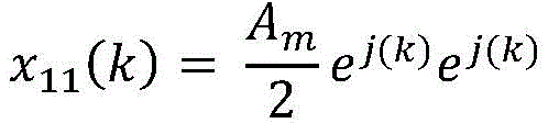
x(k)=x11(k)+x12(k) (1.3)x(k)=x 11 (k)+x 12 (k) (1.3)
对于等式(1.3),两个恒定包络信号为:For equation (1.3), the two constant envelope signals are:

和and

如本领域技术人员所显而易见的,由(1.4)和(1.5)定义的相应信号各自具有恒定包络,其恒定包络幅值等于Am/2。As will be apparent to those skilled in the art, the corresponding signals defined by (1.4) and (1.5) each have a constant envelope with a constant envelope amplitude equal to Am/ 2.
在(1.4)和(1.5)的信号的另一示例性实现方式中,有可能按如下方式重新排列这些信号:In another exemplary implementation of the signals of (1.4) and (1.5), it is possible to rearrange the signals as follows:

和and

在等式(1.6)和(1.7)中,e(k)为误差函数,定义如下:In equations (1.6) and (1.7), e(k) is the error function, defined as:

在等式(1.8)中,已在上文中定义了cosΦ(k)。In equation (1.8), cosΦ(k) has been defined above.
分解信号的后续信号合成涉及等式(1.6)和(1.7)的信号相加。这导致正误差函数值和负误差函数值在相加时相互抵消。由于误差函数将在信号合成阶段被抵消,因此误差函数的存在仅影响信号包络的动态范围,而不会影响最终合并后的信号结果。Subsequent signal synthesis of the decomposed signal involves the addition of the signals of equations (1.6) and (1.7). This causes the positive and negative error function values to cancel each other out when added. Since the error function will be cancelled out during the signal synthesis stage, the presence of the error function only affects the dynamic range of the signal envelope, not the final combined signal result.
注意,可以简化等式(1.6)和(1.7),因为不需要计算e(k)得到精确值,而是得到估计值。例如,如本领域所理解的,坐标旋转数字计算机(Coordinate Rotation DigitalComputer,CORDIC)算法可用于估计误差函数。Note that equations (1.6) and (1.7) can be simplified because e(k) does not need to be calculated to get the exact value, but rather an estimated value. For example, a Coordinate Rotation Digital Computer (CORDIC) algorithm can be used to estimate the error function, as understood in the art.
将等式(1.8)替换为等式(1.4)和(1.5),得到:Replacing equation (1.8) with equations (1.4) and (1.5) yields:

和and

以下步骤证明上述等式等同于等式(1.4)和(1.5)。上述等式可以简化为:The following steps prove that the above equations are equivalent to equations (1.4) and (1.5). The above equation can be simplified to:

和and

指数函数可以用余弦和正弦函数表示,如下:Exponential functions can be represented by cosine and sine functions as follows:

和and

通过替换等式(1.11)和(1.12)为等式(1.9)和(1.10),证明了等式(1.6)和(1.7)等同于等式(1.4)和(1.5)。Equations (1.6) and (1.7) are proved to be equivalent to equations (1.4) and (1.5) by replacing equations (1.11) and (1.12) with equations (1.9) and (1.10).
还参考图1,高层110b……110n分别用于执行进一步信号分解。如本文更详细地描述,由于从第一层110a接收的两个信号中的每个信号具有恒定包络,因此第二层110b至第n层110n还可以用于输出具有恒定包络的分解信号。Referring also to FIG. 1 ,
参考图2,图2示出了原始输入信号108和第一层110a的振幅包络值的图200。图200是振幅对样本关系的图。第一层110a分解算法可以完全分解为两个恒定包络信号,每个包络信号的信号振幅动态范围为‘dy’。本文认识到,仅迭代此算法不能进一步减小图200中所示的信号振幅动态范围‘dy’。在示例性实施例中,阈值算法用于进一步分解两个恒定包络信号,以进一步减小每个信号的动态范围,而不影响每个信号的包络特性或对每个信号的包络特性的影响最小(例如,保持较小PAPR,保持恒定包络)。Referring to FIG. 2, a
第二层110b至第n层110n的阈值算法用于进一步分解信号以减小动态范围和信号振幅。根据阈值‘d’确定阈值算法,如下:The thresholding algorithm of the

和and

在示例性实施例中,‘d’的值是范围0<d<Am内的预定义值。Am为原始输入信号108的振幅的最大值。In an exemplary embodiment, the value of 'd' is a predefined value in the
在另一示例性实施例中,可以选择或编程‘d’的值以把每个层中的分解信号的不同幅值作为目标幅值。如图3所示,经过若干层后,信号振幅可以减小。In another exemplary embodiment, the value of 'd' may be selected or programmed to target different amplitudes of the decomposed signal in each layer. As shown in Figure 3, after passing through several layers, the signal amplitude can be reduced.
图3示出了原始输入信号108和第一层110a、第二层110b和第三层110c的振幅包络值的图300。图300类似于图2的图200,并进一步示出了第二层110b和第三层110c的振幅包络值。如图3所示,在对称分解的示例性实施例中,计算每个‘d’值为从上一层接收的输入信号振幅的一半。在未示出的另一示例性实施例中,存在不对称分解,其中‘d’的值不是从上一层接收的输入信号的一半。3 shows a
在示例性实施例中,在第二层110b和高层中迭代地使用同一阈值算法。层数可根据系统设计要求确定。可以选择每个层110的‘d’的值作为大于零且小于当前层110的输入信号的恒定包络幅值的值。In an exemplary embodiment, the same thresholding algorithm is used iteratively in the
每个层110输出与从上一层110接收的输入信号相比已减小动态范围的分解信号。此外,与从上一层110接收的输入信号相比,每个层110的分解信号可以使用较少数量的量化比特来表示。Each layer 110 outputs a decomposed signal having reduced dynamic range compared to the input signal received from the previous layer 110 . Furthermore, the decomposed signal of each layer 110 can be represented using a smaller number of quantization bits than the input signal received from the previous layer 110 .
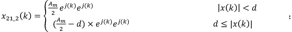
参考图4,图4更详细地示出了系统100。第二层110b分别处理从第一层110a接收的两个输入信号。第二层110b执行分解后的结果输出为每个输入信号的两个输出信号,共四个输出信号。在示例性实施例中,可以使用两个相同的功能模块来定义第二层110b分解。Referring to FIG. 4, the
再参考图4,第二层110b、模块1输出信号为:Referring to FIG. 4 again, the output signal of the

和and

第二层110b、模块2输出信号为:The output signal of the

和and

两层以上,原理相同。每个输入信号分解为两个输出信号。More than two layers, the principle is the same. Each input signal is decomposed into two output signals.
对于图4中x的下标,第一个数字表示层,第二个数字表示该层的模块号或模块ID,第三个数字表示该模块号的分支。例如,对于图4中示出的‘x31_2(k)’,‘3’表示第三层110c的信号输出,‘1’表示第三层110c的第一模块(‘模块1’),‘2’表示第三层110c的模块1的第二分支。For the subscript of x in Figure 4, the first number represents the layer, the second number represents the module number or module ID of the layer, and the third number represents the branch of the module number. For example, for 'x 31_2 (k)' shown in FIG. 4, '3' represents the signal output of the
下文说明在每个层110都保持恒定振幅包络。对于第二层110b,等式(1.4)是信号输入,并且可以按如下方式插入等式(2.1)和(2.2)中:A constant amplitude envelope is maintained at each layer 110 as described below. For the
和and

上述等式可以简化为:The above equation can be simplified to:

和and

该信号保持恒定的包络特性,但减小了动态范围。对于其它分支和层,也有可能得到相同的结果。数学等式映射如图4所示。The signal maintains a constant envelope characteristic, but reduces the dynamic range. It is possible to get the same result for other branches and layers. The mathematical equation mapping is shown in Figure 4.
现参考图5和图6,图1示出了示例性实施例提供的系统100的层控制。图5示出了层控制的逻辑图500,图6示出了图1的系统100实现层控制的框图。迭代地将源信号分解为进一步分解的信号,直到确定了指定条件。Referring now to Figures 5 and 6, Figure 1 illustrates layer control of a
层数可以通过目标动态范围Atg控制。方框502接收原始输入信号108。方框504确定恒定包络振幅。方框506检查恒定振幅是否大于指定时间段Ttg的目标动态范围Atg(事件514)。如果是,则通过控制方框508启用信号分解方框510来执行信号分解。如果否,则方法500结束,并且子系统104可以对最终分解的信号执行其它过程,例如,由滤波器112执行。在示例性实施例中,延迟512方框导致信号分解方框510的延迟。信号分解方框510循环回到方框502,并返回刚完成层110的输出,以执行下一次迭代。分解方框510用于首先执行层1(110a),然后对于后续迭代,分解方框510执行高层,例如从第二层110b到第n层110n。在示例性实施例中,来自第n层110n的最终分解信号随后被存储到存储器中,或发送到其它子系统以进行任何或所有处理、传输和重组。The number of layers can be controlled by the target dynamic range Atg .
参考图6,通过将输入信号与目标Atg进行比较(方框506),当输入|x(k)|小于或等于目标Atg时,停止信号分解(方框510)。在一些示例性实施例中,Atg和检查时长514都是可以预定义的设计参数。在其它示例性实施例中,可以实时确定Atg和检查时长514。6, by comparing the input signal with the target Atg (block 506), when the input |x(k)| is less than or equal to the target Atg , the signal decomposition is stopped (block 510). In some exemplary embodiments, Atg and
在示例性实施例中,当层中的任一输出信号的包络幅度值达到目标Atg时,停止信号分解(方框510)。例如,在对称分解的情况下,仅需要将其中一个输出信号与目标Atg进行比较,因为其余信号具有相同的包络幅值。在另一示例性实施例中,当层中的所有输出信号的包络幅值达到目标Atg时,停止信号分解(方框510)。例如,在非对称分解的情况下,可以将所有输出信号与目标Atg进行比较,以便当所有输出信号的最大幅值小于目标值时停止信号分解(方框510)。In an exemplary embodiment, when the envelope amplitude value of any of the output signals in the layer reaches the target Atg , the signal decomposition is stopped (block 510). For example, in the case of symmetric decomposition, only one of the output signals needs to be compared to the target Atg , since the remaining signals have the same envelope amplitude. In another exemplary embodiment, signal decomposition is stopped when the envelope amplitudes of all output signals in the layer reach the target Atg (block 510). For example, in the case of an asymmetric decomposition, all output signals may be compared to a target Atg to stop signal decomposition when the maximum magnitude of all output signals is less than the target value (block 510).
图7示出了示例性实施例提供的资源减少的信号处理系统100。与图4中示出的信号处理系统100相比,通过计算每一层的特定‘d’值,有可能通过关闭某些分支,例如每个模块中的两个分支中的一个来减少资源。FIG. 7 illustrates a
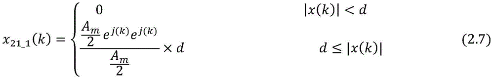
为了说明如何关闭某些分支,在等式(2.9)和(2.10)中,用Am/2代替阈值‘d’。To illustrate how to turn off certain branches, in equations (2.9) and (2.10), the threshold ' d ' is replaced by Am/2.

和and

在图4的系统100中,第二层110b、模块1可用于计算x21_1和x21_2。从等式(2.11)和等式(2.12)可以看出,x21_1和x21_2有一个公共分量

图7所示的系统100示出了资源减少的高级框图。只需要计算等式(2.11)和(2.12)中的一个,其中需要对一个输出进行处理并保存到存储器中。因此,这可以减少硬件或软件资源,而不会影响性能。在图7的系统100中,对于第二层110b至第n层11n,只需要为每个输入信号计算一个分解输出信号。这与图4中所示的系统100的实现方式形成对比,该系统在每个层110处的分解输出信号呈指数增长。The
现参考图8,图8示出了信号处理系统100的第二层110b的模块1的模拟结果的图800。如图8所示,可通过编程阈值‘d’获得同一层内信号的不同动态范围。还单独示出了第一分支802和第二分支804的图。Referring now to FIG. 8 , a
图9A示出了仅具有阈值分解的现有技术系统的频谱图900。换句话说,不存在初始恒定包络分解算法。图900示出了原始信号以及第一输出和第二输出(分别为‘s1’或‘s2’)。图9B示出了示例性实施例提供的原始信号和第一层110a信号输出(分别为‘s1’或‘s2’)的频谱图910。在图示的对称情况下,出于说明的目的,s1和s2通常重叠,因此显示为同一信号。9A shows a
从频谱图900中可以看出,由于s1和s2的恒定振幅包络,s1和s2的带宽比原始信号窄且定义更明确。原始信号的带宽要宽得多。As can be seen from the
图10A示出了仅具有阈值分解的图9A所述的现有技术系统的性能的峰均功率比(Peak-to-Average Power Ratio,PAPR)图1000。X轴是‘原始信号’(图1的输入信号108)的PAPR。图示的“原始信号”仅用作对X轴的参考。纵轴表示PAPR大于参考源信号PAPR的概率。相对于Y轴绘制的是仅阈值分解的第二分支‘s2’的输出、仅阈值分解的第二分支‘s2-filt’的滤波输出,以及仅阈值分解的第一分支‘s1-filt’的滤波输出。FIG. 10A shows a Peak-to-Average Power Ratio (PAPR)
图10B示出了示例性实施例提供的图1的信号处理系统100的输出的峰均功率比(Peak-to-Average Power Ratio,PAPR)图1010。X轴是‘原始信号’(图1的输入信号108)的PAPR。图示的原始信号仅用作对X轴的参考。纵轴表示PAPR大于参考源信号PAPR的概率。相对于Y轴绘制的是‘s1’和‘s2’的输出。在图示的对称情况下,‘s1’和‘s2’通常重叠,因此显示为同一信号。如图1010所示,与原始信号相比,s1和s2的PAPR通常较低,特别是原始信号的PAPR较高。FIG. 10B illustrates a Peak-to-Average Power Ratio (PAPR)
图10C示出了分解模块102的误差对比频谱图1020。以分贝(dB)和频率(MHz)为单位显示原始信号以及由于分解模块102对原始信号的分解而产生的误差。FIG. 10C shows an
下表总结了现有技术仅阈值分解系统的模拟结果与分解模块102的性能的模拟结果。The following table summarizes the simulation results of the prior art threshold-only decomposition system and the simulation results of the performance of the
表1Table 1


在表1中,“量化比特”是指用于表示相应分解信号的比特数,“平均误差向量幅度(Average Error vector Magnitude,EVM),%”表示与特定的量化比特集的原始信号的偏移量。在表1中,空白表项意味着模拟没有精确的量化比特值,而量化比特值正好对应于特定的量化比特集。In Table 1, "quantization bits" refers to the number of bits used to represent the corresponding decomposed signal, and "Average Error Vector Magnitude (EVM), %" represents the offset from the original signal of a particular quantization bit set quantity. In Table 1, a blank entry means that the simulation has no precise quantization bit value, which corresponds to a specific quantization bit set.
在表1中,仅阈值分解产生两个分解信号,表示为‘s1’和‘s2’。参见图4和表1,对于分解模块102,‘s1’表示x21_1(k),‘s2’表示x21_3(k),‘s3’表示x22_1(k),‘s4’表示x22_2(k)。在表1中,分解模块102也表示对称分解的情况。因此,表1中所示的结果仅针对分解信号‘s1’和‘s3’。注意,在这种对称分解情况下,‘s2’和‘s4’(未示出)不需要用量化比特表示,因为它们随后可以分别从‘s1’和‘s3’恢复,如上文关于等式(2.11)和(2.12)所述。In Table 1, threshold-only decomposition yields two decomposition signals, denoted 's1' and 's2'. 4 and Table 1, for the
从表1中可以看出,在“浮点(float)”和“10”等较高量化比特值下,分解模块102的性能与仅阈值分解相当。在较低量化比特值下,分解模块102执行比仅阈值分解的EVM更好的操作。例如,在量化比特‘6’的情况下,仅阈值分解的EVM百分比为2.94,分解模块102的EVM百分比为1.7。As can be seen from Table 1, at higher quantization bit values, such as "float" and "10", the performance of the
从表1中得出的类似结论是,为实现类似的EVM,分解模块102通常需要比仅阈值分解更少的量化比特,特别是在量化比特值较低的情况下。A similar conclusion from Table 1 is that to achieve a similar EVM, the
再次参考图1,子系统104仅接收最终分解信号,例如,最终分解信号的动态范围和约束带宽比原始信号108更小。最终分解信号的这些特性可以提高子系统104的性能。Referring again to FIG. 1 , the
图11示出了示例性实施例提供的重构模块106的框图。在示例性实施例中,例如,重构模块106用于通过反向执行分解模块102的功能,重构或重组来自一个或多个子系统104的接收信号。因此,重构模块106产生恢复信号114。重构模块106包括相加模块110。FIG. 11 shows a block diagram of the
例如,在图4中,可以从第n层110n输出多个分解信号。在图11中,相加模块1100接收这些多个分解信号作为多个输入信号。例如,相加模块1100用于通过将接收到的多个输入信号相加而生成恢复信号114。For example, in FIG. 4, a plurality of decomposed signals may be output from the
图12示出了示例性实施例提供的重构模块106在对称分解情况下的框图。图12的重构模块106用于重构由于对称分解而输出的分解信号的情况,如图7的系统100的情况。如在相加模块1102处所示,重构模块106仅需要接收正好两个输入信号(两个输入信号对应于来自图7的系统100的两个主要输出信号)。相加模块1102将两个输入信号相加在一起。比例因子1104也应用于模块1102,在示例性实施例中,比例因子1104可以是预定义的比例因子。与图11中接收两个以上输入信号的相加模块1100相比,图12中的相加模块1102不需要接收两个以上主输入信号。FIG. 12 shows a block diagram of the
参考图1,在示例性实施例中,层110的数量可以变化。依次进行分解,直到分解信号达到目标振幅Atg。在示例性实施例中,层数通过实时自动层控制来确定。在示例性实施例中,当输入信号到达|x|<Atg一定时间段Ttg后,停止信号分解。在另一示例性实施例中,可以预定义层数。Referring to FIG. 1, in an exemplary embodiment, the number of layers 110 may vary. Decomposition is performed sequentially until the decomposed signal reaches the target amplitude Atg . In an exemplary embodiment, the number of layers is determined by real-time automatic layer control. In an exemplary embodiment, the signal decomposition is stopped when the input signal reaches |x|<A tg for a certain period of time T tg . In another exemplary embodiment, the number of layers may be predefined.
可以理解的是,可以选择为0和Am之间的任何值作为阈值‘d’。在示例性实施例中,系统100可用于产生对称或非对称分解信号。It will be appreciated that any value between 0 and Am can be chosen as the threshold ' d '. In an exemplary embodiment,
此外,混合多层架构使得在示例性实施例中可以使用一个或多个滤波器112,例如低通滤波器或带通滤波器,而不会显著减小PAPR。Furthermore, the hybrid multi-layer architecture allows one or
在示例性实施例中,信号分解可以改善子系统104的系统动态范围或功率效率,例如,使用非线性组件(nonlinear component,LINC)功率放大器(power Amplifier,PA)的LInear放大。In an exemplary embodiment, signal decomposition may improve the system dynamic range or power efficiency of the
在示例性实施例中,分解信号减少了带宽扩展。例如,受限带宽可产生PAPR小于3dB的分解信号。In an exemplary embodiment, decomposing the signal reduces bandwidth spread. For example, a limited bandwidth can produce a decomposed signal with a PAPR of less than 3dB.
在示例性实施例中,如本领域所理解,系统100由个人基本服务集(personalbasic service set,PBSS)控制点(PBSS control point,PCP)、接入点(access point,AP)或站台(station,STA)实现。In an exemplary embodiment, the
在示例性实施例中,系统100的至少一个模块由电子组件实现。例如,分解模块102可以由分解模块电子组件来实现。电子组件可以提供为半导体电路,例如形成集成电路封装的部分或全部。电路可以是数字电路或模拟电路。在一些实施例中,根据指定数量的层、指定阈值‘d’、处理特定源信号的指定时间段或其它指定阈值等对电路进行预配置。在其它实施例中,电路通过控制接口或用户接口可重新配置和重新编程。In an exemplary embodiment, at least one module of
一些示例性实施例应用于毫米波(mm波)无线通信系统中的信号处理。一些示例性实施例适用于Wi-Fi(Wi-Fi,TM)通信系统中的信号处理,如标准IEEE 802.11系列中所述。容易理解的是,示例性实施例可以应用于其它无线通信系统,以及有线或光学系统,以及其它通信环境中。Some example embodiments apply to signal processing in millimeter-wave (mm-wave) wireless communication systems. Some exemplary embodiments are applicable to signal processing in Wi-Fi (Wi-Fi, TM) communication systems, as described in the IEEE 802.11 series of standards. It will be readily understood that the exemplary embodiments may be applied in other wireless communication systems, as well as in wired or optical systems, and in other communication environments.
一些示例性实施例应用于单信道系统、多信道系统、波束成形、多信道系统、多输入多输出(multiple-input-multiple-output,MIMO)系统、大规模MIMO系统、多信道系统或多载波系统中的信号处理。一些示例性实施例可以应用于包括4G在内的有线或无线系统,旨在覆盖和涵盖包括5G在内的更高代系统。Some example embodiments apply to single-channel systems, multi-channel systems, beamforming, multi-channel systems, multiple-input-multiple-output (MIMO) systems, massive MIMO systems, multi-channel systems, or multi-carrier Signal processing in the system. Some example embodiments may be applied to wired or wireless systems, including 4G, and are intended to cover and encompass higher generation systems, including 5G.
通过上述示例性实施例的描述,上述示例性实施例可以仅通过硬件实现,也可以通过软件和必要的通用硬件平台实现。基于这样的理解,示例性实施例的技术方案可以以软件产品的形式体现。软件产品可以存储在非易失性或非瞬时性存储介质中,非易失性或非瞬时性存储介质可以是光盘只读存储器(compact disk read-only memory,CD-ROM)、USB闪存盘或移动硬盘。软件产品包括许多指令,使得计算机设备(个人计算机、服务器或网络设备)能够执行示例性实施例提供的方法。例如,这样的执行可以对应于如本文所述的逻辑操作的模拟。根据示例性实施例,软件产品可以额外或替代性地包括使得计算机设备执行配置或编程数字逻辑装置的操作的多个指令。Through the description of the above-mentioned exemplary embodiments, the above-mentioned exemplary embodiments can be implemented only by hardware, and can also be implemented by software and a necessary general hardware platform. Based on such understanding, the technical solutions of the exemplary embodiments may be embodied in the form of software products. The software product may be stored in a non-volatile or non-transitory storage medium, which may be a compact disk read-only memory (CD-ROM), a USB flash drive, or mobile hard drive. A software product includes a number of instructions that enable a computer device (personal computer, server, or network device) to perform the methods provided by the exemplary embodiments. For example, such execution may correspond to the simulation of logical operations as described herein. According to an exemplary embodiment, a software product may additionally or alternatively include a plurality of instructions that cause a computer device to perform operations to configure or program a digital logic device.
本文描述的示例装置和方法根据示例性实施例可以由一个或多个控制器实施。控制器可以包括硬件、软件或硬件和软件的组合,具体取决于特定的应用、组件或功能。在一些示例性实施例中,一个或多个控制器可以包括模拟或数字组件,并且可以包括一个或多个处理器、一个或多个非瞬时性存储介质,例如存储可由一个或多个处理器、一个或多个收发器(或单独的发射器和接收器)、一个或多个信号处理器(如模拟信号处理器和数字信号处理器之一或两者)以及一个或多个模拟电路组件中的至少一个执行的指令的存储器。The example apparatus and methods described herein may be implemented by one or more controllers according to example embodiments. A controller may include hardware, software, or a combination of hardware and software, depending on the particular application, component, or function. In some demonstrative embodiments, one or more controllers may include analog or digital components, and may include one or more processors, one or more non-transitory storage media, such as storage that may be stored by the one or more processors , one or more transceivers (or separate transmitters and receivers), one or more signal processors (eg, one or both of an analog signal processor and a digital signal processor), and one or more analog circuit components at least one of the executed instructions in the memory.
在所描述的方法或框图中,方框可以表示事件、步骤、函数、过程、模块、消息和基于状态的操作等中的任一个或全部。尽管上述一些示例已被描述为以特定顺序发生,本领域技术人员将理解,只要任何给定步骤的顺序改变的结果不会阻止或损害后续步骤的发生,则某些步骤或过程可以以不同的顺序执行。此外,上述一些消息或步骤在其它实施例中可以删除或合并,并且上述一些消息或步骤在其它实施例中可以拆分为多个子消息或子步骤。甚至可以根据需要重复一些或所有步骤。描述为方法或步骤的元件同样适用于系统或子部件,反之亦然。提及“发送”或“接收”等词,可根据特定设备的作用而互换。In the described methods or block diagrams, blocks may represent any or all of events, steps, functions, procedures, modules, messages, state-based operations, and the like. Although some of the above examples have been described as occurring in a particular order, those skilled in the art will understand that certain steps or processes may be performed differently, as long as the result of any given step changing the order does not prevent or impair the occurrence of subsequent steps. Execute sequentially. In addition, some of the above-mentioned messages or steps may be deleted or combined in other embodiments, and some of the above-mentioned messages or steps may be split into multiple sub-messages or sub-steps in other embodiments. You can even repeat some or all of the steps as needed. Elements described as methods or steps are equally applicable to systems or subcomponents, and vice versa. Words like "send" or "receive" are mentioned interchangeably depending on what a particular device does.
以上所讨论的实施例是说明性的,而非限制性的。描述为方法的示例性实施例同样适用于系统,反之亦然。The embodiments discussed above are illustrative, not restrictive. Exemplary embodiments described as methods are equally applicable to systems and vice versa.
可以改变一些示例性实施例,包括任何上述实施例的组合和子组合。以上所示的示例性实施例仅是示例,决不旨在限制本发明的范围。本文描述的创新变化对于本领域普通技术人员而言将是显而易见的,这些变化在本发明的预期范围内。特定而言,可以选择一个或多个上述实施例的特征来创建包括可能未在上文明确描述的特征的子组合的替代性实施例。此外,可以选择并组合一个或多个上述实施例的特征来创建包括可能未在上文明确描述的特征的组合的替代性实施例。在整体回顾本发明后,适合这种组合和子组合的特征对于本领域技术人员而言将是显而易见的。本文所描述的主题旨在覆盖和涵盖所有适当的技术变更。Some exemplary embodiments may vary, including combinations and sub-combinations of any of the above-described embodiments. The exemplary embodiments shown above are only examples and are in no way intended to limit the scope of the present invention. The innovative variations described herein will be apparent to those of ordinary skill in the art and are within the intended scope of the present invention. In particular, the features of one or more of the above-described embodiments may be selected to create alternative embodiments comprising sub-combinations of features that may not be explicitly described above. Furthermore, the features of one or more of the above-described embodiments may be selected and combined to create alternative embodiments including combinations of features that may not be expressly described above. Features suitable for such combinations and subcombinations will be apparent to those skilled in the art after reviewing the present invention as a whole. The subject matter described herein is intended to cover and cover all appropriate technical changes.
因此,本说明书和附图应仅作为说明,并包括任何和所有修改、变体、组合或等同物。Accordingly, this specification and drawings are to be regarded as illustrative only and include any and all modifications, variations, combinations or equivalents.
Claims (28)


Applications Claiming Priority (3)
| Application Number | Priority Date | Filing Date | Title |
|---|---|---|---|
| US15/876,950 US10361895B1 (en) | 2018-01-22 | 2018-01-22 | Systems and methods for hybrid multi-layer signal decomposition |
| US15/876,950 | 2018-01-22 | ||
| PCT/CN2019/072385 WO2019141249A1 (en) | 2018-01-22 | 2019-01-18 | Systems and methods for hybrid multi-layer signal decomposition |
Publications (2)
| Publication Number | Publication Date |
|---|---|
| CN111656743A true CN111656743A (en) | 2020-09-11 |
| CN111656743B CN111656743B (en) | 2021-10-22 |
Family
ID=67299422
Family Applications (1)
| Application Number | Title | Priority Date | Filing Date |
|---|---|---|---|
| CN201980008311.3A Active CN111656743B (en) | 2018-01-22 | 2019-01-18 | Hybrid multi-layer signal decomposition method and device |
Country Status (3)
| Country | Link |
|---|---|
| US (1) | US10361895B1 (en) |
| CN (1) | CN111656743B (en) |
| WO (1) | WO2019141249A1 (en) |
Cited By (1)
| Publication number | Priority date | Publication date | Assignee | Title |
|---|---|---|---|---|
| CN118827306A (en) * | 2024-07-01 | 2024-10-22 | 芯百特微电子(无锡)有限公司 | A method, system, device and medium for reducing high PAPR waveform in radio frequency power amplifier |
Citations (4)
| Publication number | Priority date | Publication date | Assignee | Title |
|---|---|---|---|---|
| US20140266464A1 (en) * | 2013-03-13 | 2014-09-18 | Futurewei Technologies, Inc. | Apparatus and Method for Asymmetrically Driven Partial Outphasing Power Amplifier |
| CN104796091A (en) * | 2015-04-13 | 2015-07-22 | 南京理工大学 | Polynomial power amplifier modeling and digital pre-distorting method based on segmented memory |
| CN106102156A (en) * | 2016-05-30 | 2016-11-09 | 成都理工大学 | Linearisation transmission method based on multiple antennas |
| CN106198013A (en) * | 2016-06-29 | 2016-12-07 | 潍坊学院 | A kind of envelope Analysis Method based on empirical mode decomposition filtering |
Family Cites Families (3)
| Publication number | Priority date | Publication date | Assignee | Title |
|---|---|---|---|---|
| US7355470B2 (en) * | 2006-04-24 | 2008-04-08 | Parkervision, Inc. | Systems and methods of RF power transmission, modulation, and amplification, including embodiments for amplifier class transitioning |
| EP1902526A4 (en) * | 2005-05-27 | 2009-11-11 | Ahmed Birafane | High effeciency rf transmitter system using non-linear amlifiers |
| US8482462B2 (en) * | 2007-05-25 | 2013-07-09 | Rambus Inc. | Multi-antenna beam-forming system for transmitting constant envelope signals decomposed from a variable envelope signal |
-
2018
- 2018-01-22 US US15/876,950 patent/US10361895B1/en active Active
-
2019
- 2019-01-18 WO PCT/CN2019/072385 patent/WO2019141249A1/en not_active Ceased
- 2019-01-18 CN CN201980008311.3A patent/CN111656743B/en active Active
Patent Citations (4)
| Publication number | Priority date | Publication date | Assignee | Title |
|---|---|---|---|---|
| US20140266464A1 (en) * | 2013-03-13 | 2014-09-18 | Futurewei Technologies, Inc. | Apparatus and Method for Asymmetrically Driven Partial Outphasing Power Amplifier |
| CN104796091A (en) * | 2015-04-13 | 2015-07-22 | 南京理工大学 | Polynomial power amplifier modeling and digital pre-distorting method based on segmented memory |
| CN106102156A (en) * | 2016-05-30 | 2016-11-09 | 成都理工大学 | Linearisation transmission method based on multiple antennas |
| CN106198013A (en) * | 2016-06-29 | 2016-12-07 | 潍坊学院 | A kind of envelope Analysis Method based on empirical mode decomposition filtering |
Non-Patent Citations (1)
| Title |
|---|
| NEUL等: "《3GPP TSG RAN WG1 Meeting #83 R1-156926》", 22 November 2015 * |
Cited By (1)
| Publication number | Priority date | Publication date | Assignee | Title |
|---|---|---|---|---|
| CN118827306A (en) * | 2024-07-01 | 2024-10-22 | 芯百特微电子(无锡)有限公司 | A method, system, device and medium for reducing high PAPR waveform in radio frequency power amplifier |
Also Published As
| Publication number | Publication date |
|---|---|
| CN111656743B (en) | 2021-10-22 |
| WO2019141249A1 (en) | 2019-07-25 |
| US10361895B1 (en) | 2019-07-23 |
| US20190229966A1 (en) | 2019-07-25 |
Similar Documents
| Publication | Publication Date | Title |
|---|---|---|
| US9667299B2 (en) | Systems and methods for non-linear digital self-interference cancellation | |
| US9455761B2 (en) | Systems and methods for multi-rate digital self-interference cancellation | |
| JP5739553B2 (en) | Method and apparatus for signal compression and decompression | |
| CN112514337B (en) | Distribution matching circuit, distribution dematching circuit, distribution matching method, distribution dematching method, and optical transmission system | |
| KR102088528B1 (en) | Apparatus and method for encoding and decoding for frequency-quadrature amplitude modulation in wireless communication system | |
| AU2018305459C1 (en) | Polar coding method and apparatus | |
| Yuksel | Stochastic stabilization of noisy linear systems with fixed-rate limited feedback | |
| KR102241416B1 (en) | Apparatus and method for decoding low density parity check(ldpc) codes in digital video broadcasting(dvb) system | |
| CN111786926B (en) | Receiving device, receiving method, sending device and sending method | |
| JP2016533687A (en) | Multi-carrier peak suppression processing method and apparatus | |
| CN117411596B (en) | Demodulation method, demodulation device, storage medium and electronic equipment | |
| US20150003502A1 (en) | N-Order Noise Shaper | |
| CN111656743A (en) | Hybrid multilayer signal decomposition system and method | |
| US20190173502A1 (en) | Transmission device, reception device, transmission method, and reception method | |
| CN118631625B (en) | OTFS peak-to-average ratio suppression method, device and electronic device based on preset peak clipping signal | |
| CN111478705B (en) | Gain control method, device and circuit based on receiver and receiver | |
| KR20210034411A (en) | An wireless communication appartus inclduing a data compressor and operating method thereof | |
| WO2022052933A1 (en) | Signal processing method and related device | |
| WO2022253400A1 (en) | Radio transmitter | |
| CN109417763B (en) | Signal transmission method, system and device | |
| CN119094295B (en) | Dynamic signal modulation method, device and equipment based on amplitude phase shift keying | |
| US20230259777A1 (en) | Transmission apparatus, transmission method, control circuit, and storage medium | |
| Reddy et al. | Ber analysis of cvsd vocoder for wimax using gnu radio | |
| Tienda-Luna et al. | Iterative decoding in factor graph representation using particle filtering | |
| CN115664555A (en) | Local correction method, device, equipment and medium for a signal transceiver |
Legal Events
| Date | Code | Title | Description |
|---|---|---|---|
| PB01 | Publication | ||
| PB01 | Publication | ||
| SE01 | Entry into force of request for substantive examination | ||
| SE01 | Entry into force of request for substantive examination | ||
| GR01 | Patent grant | ||
| GR01 | Patent grant |