CN111624444A - Distribution line ground fault positioning method and device - Google Patents
Distribution line ground fault positioning method and device Download PDFInfo
- Publication number
- CN111624444A CN111624444A CN202010505220.5A CN202010505220A CN111624444A CN 111624444 A CN111624444 A CN 111624444A CN 202010505220 A CN202010505220 A CN 202010505220A CN 111624444 A CN111624444 A CN 111624444A
- Authority
- CN
- China
- Prior art keywords
- fault
- distribution line
- current
- point
- line
- Prior art date
- Legal status (The legal status is an assumption and is not a legal conclusion. Google has not performed a legal analysis and makes no representation as to the accuracy of the status listed.)
- Granted
Links
- 238000000034 method Methods 0.000 title claims abstract description 61
- 230000005540 biological transmission Effects 0.000 claims abstract description 13
- 238000002347 injection Methods 0.000 claims description 26
- 239000007924 injection Substances 0.000 claims description 26
- 238000001514 detection method Methods 0.000 claims description 17
- 230000002159 abnormal effect Effects 0.000 claims description 14
- 238000007689 inspection Methods 0.000 claims description 12
- 238000012360 testing method Methods 0.000 claims description 8
- 230000009191 jumping Effects 0.000 claims description 3
- 239000003990 capacitor Substances 0.000 description 2
- 238000010586 diagram Methods 0.000 description 2
- 239000000243 solution Substances 0.000 description 2
- 230000009286 beneficial effect Effects 0.000 description 1
- 230000000694 effects Effects 0.000 description 1
- 238000009413 insulation Methods 0.000 description 1
- 239000012212 insulator Substances 0.000 description 1
- 239000000463 material Substances 0.000 description 1
- 230000000750 progressive effect Effects 0.000 description 1
- 238000011084 recovery Methods 0.000 description 1
- 239000002699 waste material Substances 0.000 description 1
Images


Classifications
-
- G—PHYSICS
- G01—MEASURING; TESTING
- G01R—MEASURING ELECTRIC VARIABLES; MEASURING MAGNETIC VARIABLES
- G01R31/00—Arrangements for testing electric properties; Arrangements for locating electric faults; Arrangements for electrical testing characterised by what is being tested not provided for elsewhere
- G01R31/08—Locating faults in cables, transmission lines, or networks
- G01R31/11—Locating faults in cables, transmission lines, or networks using pulse reflection methods
-
- G—PHYSICS
- G01—MEASURING; TESTING
- G01R—MEASURING ELECTRIC VARIABLES; MEASURING MAGNETIC VARIABLES
- G01R31/00—Arrangements for testing electric properties; Arrangements for locating electric faults; Arrangements for electrical testing characterised by what is being tested not provided for elsewhere
- G01R31/08—Locating faults in cables, transmission lines, or networks
- G01R31/081—Locating faults in cables, transmission lines, or networks according to type of conductors
- G01R31/085—Locating faults in cables, transmission lines, or networks according to type of conductors in power transmission or distribution lines, e.g. overhead
-
- G—PHYSICS
- G01—MEASURING; TESTING
- G01R—MEASURING ELECTRIC VARIABLES; MEASURING MAGNETIC VARIABLES
- G01R31/00—Arrangements for testing electric properties; Arrangements for locating electric faults; Arrangements for electrical testing characterised by what is being tested not provided for elsewhere
- G01R31/50—Testing of electric apparatus, lines, cables or components for short-circuits, continuity, leakage current or incorrect line connections
- G01R31/52—Testing for short-circuits, leakage current or ground faults
-
- G—PHYSICS
- G01—MEASURING; TESTING
- G01R—MEASURING ELECTRIC VARIABLES; MEASURING MAGNETIC VARIABLES
- G01R31/00—Arrangements for testing electric properties; Arrangements for locating electric faults; Arrangements for electrical testing characterised by what is being tested not provided for elsewhere
- G01R31/50—Testing of electric apparatus, lines, cables or components for short-circuits, continuity, leakage current or incorrect line connections
- G01R31/58—Testing of lines, cables or conductors
-
- Y—GENERAL TAGGING OF NEW TECHNOLOGICAL DEVELOPMENTS; GENERAL TAGGING OF CROSS-SECTIONAL TECHNOLOGIES SPANNING OVER SEVERAL SECTIONS OF THE IPC; TECHNICAL SUBJECTS COVERED BY FORMER USPC CROSS-REFERENCE ART COLLECTIONS [XRACs] AND DIGESTS
- Y04—INFORMATION OR COMMUNICATION TECHNOLOGIES HAVING AN IMPACT ON OTHER TECHNOLOGY AREAS
- Y04S—SYSTEMS INTEGRATING TECHNOLOGIES RELATED TO POWER NETWORK OPERATION, COMMUNICATION OR INFORMATION TECHNOLOGIES FOR IMPROVING THE ELECTRICAL POWER GENERATION, TRANSMISSION, DISTRIBUTION, MANAGEMENT OR USAGE, i.e. SMART GRIDS
- Y04S10/00—Systems supporting electrical power generation, transmission or distribution
- Y04S10/50—Systems or methods supporting the power network operation or management, involving a certain degree of interaction with the load-side end user applications
- Y04S10/52—Outage or fault management, e.g. fault detection or location
Landscapes
- Physics & Mathematics (AREA)
- General Physics & Mathematics (AREA)
- Locating Faults (AREA)
Abstract
The invention discloses a distribution line ground fault positioning method and a positioning device. The distribution line ground fault positioning method mainly comprises the following steps: the method is suitable for a non-branched or less-branched AC/DC signal rapid positioning method, an AC/DC signal comprehensive positioning method, an AC signal fault positioning method and a pulse signal fault positioning method. This distribution lines earth fault positioner includes that host computer and electric current patrol the appearance, and wherein host computer and electric current patrol the appearance and all are provided with the wireless transmission unit, and the electric current patrol the appearance and can pass through wireless transmission unit control host computer, realize host computer remote operation. The distribution line ground fault positioning method and the distribution line ground fault positioning device have the advantage of high fault positioning efficiency.
Description
Technical Field
The invention relates to the technical field of line detection of power distribution systems, in particular to a distribution line ground fault positioning method and device.
Background
Distribution lines have more branches, complex network structure and higher line fault rate. The single-phase earth fault is one of the more common faults, when the system is in single-phase earth, the non-fault earth-to-earth voltage rises, various overvoltage is easily caused, intermittent electric arcs are caused, the system insulation is endangered, and a two-phase short circuit fault can be developed in severe cases. Due to the fact that single-phase earth faults are caused by a plurality of reasons, and the fault location is difficult to judge due to the long line. At present, most of the faults are searched by adopting a manual line patrol method, a large amount of time is needed for the whole line to be patrolled, the power failure time is long, especially, the traffic is inconvenient in remote areas, and the line which is short in patrol needs to be taken for several hours, so that a large amount of waste of manpower and material resources is caused.
Therefore, the development of a single-phase earth fault searching method and a fault positioning device becomes a problem which needs to be solved urgently.
Disclosure of Invention
The invention aims to provide an efficient distribution line ground fault positioning method and device.
In order to achieve the purpose, the invention provides the following scheme:
a distribution line ground fault positioning method comprises the following steps:
isolating the transformer at the user side from the distribution line;
injecting a direct-current high-voltage signal into the distribution line, and determining a fault phase according to the current value of each phase;
determining the grounding resistance of the fault phase according to the fault phase current and the injected high-voltage direct current signal;
injecting an alternating current high-voltage signal into the distribution line, and calculating a predicted distance between a fault point and an injection point of the alternating current high-voltage signal according to the voltage, the current, the capacitance current and the grounding resistance of the fault phase of the injected high-voltage alternating current signal to obtain a predicted position of the fault point;
inspecting at the predicted position, and judging whether a fault exists;
if the predicted position has no fault, injecting a high-voltage alternating current signal into the fault phase, measuring a current value within a set range of the predicted position, and judging whether the current value is smaller than a set value, if the current value is smaller than the set value, indicating that the fault position is positioned at the front end of a measuring point, inspecting whether a front end line of the measuring point has a fault, if the current value is not smaller than the set value, indicating that the fault position is positioned at the rear end of the measuring point, inspecting whether a rear end line of the measuring point has a fault, wherein the front end is close to a power supply side, and the rear end is close to a user side;
when the front-end line or the rear-end line of the measuring point is patrolled to see whether a fault exists, if no fault is found in the set range of the front-end line or the rear-end line of the measuring point, measuring the current value of a certain point of the front-end line or the rear-end line, and jumping to the step of judging whether the current value is smaller than a set value until the fault point is found.
Optionally, the method further includes:
and after the fault is determined to be recovered, injecting direct-current high voltage into the distribution line, judging whether the direct-current high voltage on the distribution line is abnormal or not when the high-voltage signal reaches the highest voltage value of the distribution line in normal operation, and if the direct-current high voltage on the distribution line is abnormal, further checking the distribution line.
The invention also provides a distribution line ground fault positioning method, which comprises the following steps:
isolating the transformer at the user side from the distribution line;
injecting a direct-current high-voltage signal into the distribution line, and determining a fault phase according to the current value of each phase;
taking a signal injection point of a distribution line as a starting point of the line, and executing a bisection method, wherein the bisection method comprises the following steps: measuring the current value of the fault phase at the middle point of the line, judging whether the current value at the measuring point is zero or not, if the current value at the measuring point is zero, indicating that the fault point is positioned on the front-end line of the measuring point, inspecting whether the front-end line of the measuring point has a fault or not, and if the current value at the measuring point is not zero, indicating that the fault point is positioned on the rear-end line of the measuring point, inspecting whether the rear-end line of the measuring point has a fault or not, wherein the front end is close to the power supply side, and the rear end is close to the user side; when whether a fault exists in the front-end line or the rear-end line of the measuring point is patrolled, if no fault is found in the set range of the front-end line or the rear-end line of the measuring point, the bisection step is circularly executed on the front-end line or the rear-end line of the measuring point until a fault point is found or the fault point is determined to be on a branch line of the distribution line;
after a fault point is determined to be on a branch line of a distribution line, a high-voltage alternating-current signal is injected into the distribution line, and a bisection step is performed on the branch line until the fault point is found.
Optionally, the method further includes:
and after the fault is determined to be recovered, injecting direct-current high voltage into the distribution line, judging whether the direct-current high voltage on the distribution line is abnormal or not when the high-voltage signal reaches the highest voltage value of the distribution line in normal operation, and if the direct-current high voltage on the distribution line is abnormal, further checking the distribution line.
The invention also provides a distribution line ground fault positioning method, which comprises the following steps:
isolating the transformer at the user side from the distribution line;
injecting a high-voltage alternating-current signal into the middle point of the distribution line;
measuring current values at two sides of the injection point;
judging whether the difference value of the current values at the two sides is smaller than a set value or not;
if yes, the line has no fault;
if not, the fault is positioned on the side with the larger current value, whether the fault exists on the side with the larger current value in the set range is determined, if the fault does not exist on the side with the larger current value in the set range, any point is determined on the side with the larger current value, the current values on the two sides of the point are measured, and the step of judging whether the difference value of the current values on the two sides is smaller than the set value is carried out until the fault point is found.
Optionally, the injection point is a midpoint of the distribution line, and any point determined on the side with the larger current value is a midpoint of the line on the side with the larger current value.
Optionally, the method further includes:
and after the fault is determined to be recovered, injecting direct-current high voltage into the distribution line, judging whether the direct-current high voltage on the distribution line is abnormal or not when the high-voltage signal reaches the highest voltage value of the distribution line in normal operation, and if the direct-current high voltage on the distribution line is abnormal, further checking the distribution line.
The invention also provides a distribution line ground fault positioning method, which comprises the following steps:
injecting a high-voltage pulse signal into the distribution line;
detecting the time of the pulse echo return, and calculating the predicted position of the fault point through the time difference;
and patrolling the predicted position of the fault point, and if no fault is found in the set range of the predicted position of the fault point, positioning the fault point by using the distribution line ground fault positioning method of claim 5.
The invention also provides a distribution line ground fault positioning device, which comprises:
a host, comprising: the device comprises a storage battery, a voltage signal converter, a CPU, a current detection unit, a voltage detection unit, a display unit, an alarm unit and a wireless transmission unit; the voltage signal converter is respectively electrically connected with the storage battery and the CPU and is used for converting the output of the storage battery according to the control of the CPU; the CPU detects the voltage value and the current value output by the host machine through the current detection unit and the voltage detection unit and outputs the voltage value and the current value to the display unit for displaying; the alarm unit is electrically connected with the CPU and used for giving an alarm when the current value or the voltage value exceeds a threshold value; the wireless transmission unit is electrically connected with the CPU;
the current inspection instrument comprises a detection end and a receiving end, wherein the detection end tests alternating current or direct current of a distribution line, transmits current data to the receiving end through a wireless module, and the receiving end is right through a wireless transmission unit and remotely controlled by a host machine.
Optionally, the voltage signal converter includes a DC-AC converter and at least one of an AC-AC converter and an AC-DC converter, wherein the DC-AC converter is configured to convert a direct current output by the storage battery into an alternating current, and the AC-AC converter is configured to boost an output of the DC-AC converter; the AC-DC converter is used for converting the output of the DC-AC converter into high-voltage direct current;
or the voltage signal converter comprises the DC-AC converter, the AC-DC converter and a pulse unit for converting the output of the AC-DC converter into a pulse signal.
According to the specific embodiment provided by the invention, the invention discloses the following technical effects: the distribution line ground fault positioning method and device provided by the invention provide a method for predicting the position of a fault point, reduce the test range and enable the fault positioning to be faster.
Drawings
In order to more clearly illustrate the embodiments of the present invention or the technical solutions in the prior art, the drawings needed in the embodiments will be briefly described below, and it is obvious that the drawings in the following description are only some embodiments of the present invention, and it is obvious for those skilled in the art to obtain other drawings without creative efforts.
Fig. 1 is a flowchart of a distribution line ground fault location method according to embodiment 1 of the present invention;
fig. 2 is a flowchart of a distribution line ground fault location method according to embodiment 2 of the present invention;
fig. 3 is a flowchart of a distribution line ground fault location method according to embodiment 3 of the present invention;
fig. 4 is a flowchart of a distribution line ground fault location method according to embodiment 4 of the present invention;
fig. 5 is a schematic structural diagram of a distribution line ground fault location device host provided in embodiment 5 of the present invention.
Detailed Description
The technical solutions in the embodiments of the present invention will be clearly and completely described below with reference to the drawings in the embodiments of the present invention, and it is obvious that the described embodiments are only a part of the embodiments of the present invention, and not all of the embodiments. All other embodiments, which can be derived by a person skilled in the art from the embodiments given herein without making any creative effort, shall fall within the protection scope of the present invention.
In order to make the aforementioned objects, features and advantages of the present invention comprehensible, embodiments accompanied with figures are described in further detail below.
The distribution line ground fault positioning method provided by the invention is suitable for the non-branched or less-branched (such as less than 5) lines.
Example 1
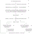
Fig. 1 is a flowchart of a distribution line ground fault positioning method according to embodiment 1 of the present invention, and as shown in fig. 1, the distribution line ground fault positioning method according to this embodiment includes the following steps:
step 101: isolating the transformer at the user side from the distribution line;
step 102: injecting a direct-current high-voltage signal into the distribution line, and determining a fault phase according to the current value of each phase;
step 103: determining the grounding resistance of the fault phase according to the fault phase current and the injected high-voltage direct current signal;
step 104: injecting an alternating current high-voltage signal into the distribution line, and calculating a predicted distance between a fault point and an injection point of the alternating current high-voltage signal according to the voltage, the current, the capacitance current and the grounding resistance of the fault phase of the injected high-voltage alternating current signal to obtain a predicted position of the fault point;
step 105: inspecting at the predicted position, and judging whether a fault exists;
step 106: if the predicted position has no fault, injecting a high-voltage alternating current signal into the fault phase, and measuring a current value within a set range of the predicted position;
step 107: judging whether the current value is smaller than a set value, wherein the set value is set by a person skilled in the art according to the actual situation;
step 108: if the current value is smaller than the set value, the fault position is located at the front end of the measuring point, and whether a fault exists in a front-end line of the measuring point is patrolled;
step 109: if the current value is not less than the set value, indicating that the fault position is located at the rear end of the measuring point, and patrolling whether a rear-end line of the measuring point has a fault or not, wherein the front end is close to the power supply side, and the rear end is close to the user side;
step 110: when whether a fault exists in the front-end line or the rear-end line of the measuring point is patrolled, if no fault is found in the set range of the front-end line or the rear-end line of the measuring point (the set range is the set range near the measuring point, and the set range is specifically set by a worker), measuring the current value of a certain point of the front-end line or the rear-end line, and jumping to step 107 until the jump is stopped after the fault point is found.
Specifically, the following may be mentioned:
s1: and after the power failure of the distribution line, disconnecting the isolating switch of the user side transformer to isolate the user side transformer from the distribution line.
S2: direct current high voltage signals are injected into the distribution line at the outlet of the transformer substation, the current abnormal phase fault phase is determined, and the direct current avoids the influence of distribution parameters of the distribution line, so that the grounding resistance value can be estimated through the following formula:
R=U/I
wherein R is fault phase grounding resistance with the unit of k omega; u is the injected fault phase voltage, unit V; i is the injection current in mA.
S3: injecting an alternating-current high-voltage signal into a distribution line at an outlet of a transformer substation, estimating the distance from a fault point to a signal injection point by the following formula,

wherein x is the distance from a fault point to a signal injection point and is in a unit of km; i is the injection current inA; u is injection voltage, unit kV, R is grounding resistance, unit k omega; i isCapacitor with a capacitor elementThe capacity current of a faultless phase per kilometer under the voltage of 1kV is unit A/(km. kV).
If the calculated x value may exist on the branch line, it is necessary to measure whether the current values of the three phases in the branch line are the same, and if the values are the same, it indicates that the fault point is on the main line, and if one of the three-phase currents is abnormal, it indicates that the fault phase is on the branch line.
S4: and the worker arrives at the injection point x for inspection, if a fault is found, the fault finding is finished, and if no fault is found, the operation goes to step S5.
S5: and injecting an alternating-current high-voltage signal into the fault phase at the outlet of the transformer substation, and detecting the current value by using a current inspection instrument near the injection point x. If the current value is larger, the current value of the rear-end line needs to be tested continuously, if the current value is zero or very small, the current value of the front-end line needs to be tested, the current values near the fault point are tested in sequence, the range is continuously reduced, and the fault point is determined finally.
S6: and after the fault is determined to be recovered, injecting direct-current high voltage into the distribution line by using the host, and if the line can bear the highest voltage value in normal operation, indicating that the distribution line can be normally put into operation. If the output current of the host reaches the upper limit of 100mA, and the direct-current high voltage is far smaller than the highest voltage value in normal operation, the circuit needs to be further checked.
Example 2
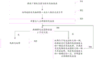
Fig. 2 is a flowchart of a distribution line ground fault positioning method according to embodiment 2 of the present invention, and as shown in fig. 2, the distribution line ground fault positioning method according to this embodiment includes the following steps:
step 201: isolating the transformer at the user side from the distribution line;
step 202: injecting a direct-current high-voltage signal into the distribution line, and determining a fault phase according to the current value of each phase;
step 203: taking a signal injection point of a distribution line as a starting point of the line, and executing a bisection method, wherein the bisection method comprises the following steps: the current value of the fault phase is measured at the middle point of the line, whether the current value at the measuring point is zero or not is judged, if the current value at the measuring point is zero, the fault point is located on the front-end line of the measuring point, whether the front-end line of the measuring point has a fault or not is observed, if the current value at the measuring point is not zero, the fault point is located on the rear-end line of the measuring point, whether the rear-end line of the measuring point has a fault or not is observed, wherein the front end is close to the power supply side, and the rear end is close to the user side. When whether a fault exists in the front-end line or the rear-end line of the measuring point is patrolled, if no fault is found in the set range of the front-end line or the rear-end line of the measuring point, the bisection step 203 is executed in a circulating mode on the front-end line or the rear-end line of the measuring point until a fault point is found or the fault point is determined to be on a branch line of the distribution line;
step 204: after determining that the fault point is on a branch line of the distribution line, injecting a high-voltage alternating current signal into the distribution line, and performing a bisection step 203 on the branch line until the fault point is found.
Specifically, the following may be mentioned:
s1: and after the power failure of the distribution line, disconnecting the isolating switch of the user side transformer to isolate the user side transformer from the distribution line.
S2: injecting a high-voltage signal into the distribution line, and searching a fault point through a current inspection instrument:
s21: and injecting an alternating current high-voltage signal at the middle point of the distribution line.
S22: and (4) testing the current values of the two sides of the injection point by using a current inspection instrument, wherein if the current values of the two sides have smaller difference and are approximately equal, the line has no fault. If the difference between the current values on both sides is large, the side with the large current value has a fault, and the process proceeds to step S23.
S23: if the current value of the rear end is larger, the high-voltage signal injection point is unchanged, and the current value is tested at the midpoint of the rear-end line by using a current inspection instrument. If the current value is larger, the fault is indicated to be at the rear end, the current value of the midpoint of the rear-end line needs to be tested continuously, if the current value is zero or very small, the fault is indicated to be at the front end, the current value of the midpoint between the point and the signal injection point is tested, the midpoint current value of the fault-side line is tested in sequence, the range is reduced continuously, and the fault point is determined finally.
S3: and after the fault is determined to be recovered, injecting direct-current high voltage into the distribution line by using the host, and if the line can bear the highest voltage value in normal operation, indicating that the distribution line can be normally put into operation. If the output current of the host reaches the upper limit of 100mA, and the direct-current high voltage is far smaller than the highest voltage value in normal operation, the circuit needs to be further checked.
Example 3
Fig. 3 is a flowchart of a distribution line ground fault positioning method according to embodiment 3 of the present invention, and as shown in fig. 3, the distribution line ground fault positioning method according to this embodiment includes the following steps:
step 301: isolating the transformer at the user side from the distribution line;
step 302: injecting a high-voltage alternating-current signal into the middle point of the distribution line;
step 303: measuring current values at two sides of the injection point;
step 304: judging whether the difference value of the current values at the two sides is smaller than a set value, wherein the set value is set by a person skilled in the art according to the actual situation;
step 305: if yes, the line has no fault;
step 306: if not, the fault is positioned on the side with the larger current value, whether the fault exists on the side with the larger current value in the set range is determined, if the fault does not exist on the side with the larger current value in the set range, any point is determined on the side with the larger current value, the current values on the two sides of the point are measured, and the step 304 is skipped until the fault point is found.
Preferably, the injection point is a midpoint of the distribution line, and any point determined on the side where the current value is larger is a midpoint of the line on the side where the current value is larger.
The method specifically comprises the following steps:
s1: and after the power failure of the distribution line, disconnecting the isolating switch of the user side transformer to isolate the user side transformer from the distribution line.
S2: and injecting a high-voltage signal into the distribution line, and searching the fault point through the current inspection instrument.
S21: and injecting an alternating current high-voltage signal at the middle point of the distribution line.
S22: and (4) testing the current values of the two sides of the injection point by using a current inspection instrument, wherein if the current values of the two sides have smaller difference and are approximately equal, the line has no fault. If the difference between the current values on both sides is large, the side with the large current value has a fault, and the process proceeds to step S23.
S23: if the current value of the rear end is larger, the high-voltage signal injection point is unchanged, and the current value is tested at the midpoint of the rear-end line by using a current inspection instrument. If the current value is larger, the fault is indicated to be at the rear end, the current value of the midpoint of the rear-end line needs to be tested continuously, if the current value is zero or very small, the fault is indicated to be at the front end, the current value of the midpoint between the point and the signal injection point is tested, the midpoint current value of the fault-side line is tested in sequence, the range is reduced continuously, and the fault point is determined finally.
S3: and after the fault is determined to be recovered, injecting direct-current high voltage into the distribution line by using the host, and if the line can bear the highest voltage value in normal operation, indicating that the distribution line can be normally put into operation. If the output current of the host reaches the upper limit of 100mA, and the direct-current high voltage is far smaller than the highest voltage value in normal operation, the circuit needs to be further checked.
Example 4
Fig. 4 is a flowchart of a distribution line ground fault positioning method according to embodiment 4 of the present invention, and as shown in fig. 4, the distribution line ground fault positioning method according to this embodiment includes the following steps:
step 401: injecting a high-voltage pulse signal into the distribution line;
step 402: detecting the time of the pulse echo return, and calculating the predicted position of the fault point through the time difference;
step 403: and patrolling the predicted position of the fault point, and if no fault is found in the set range of the predicted position of the fault point, accurately positioning the fault point by adopting the distribution line ground fault positioning method provided by the embodiment 3.
The method specifically comprises the following steps:
s1: and injecting a high-voltage pulse signal into the line with power failure.
S2: and detecting the time of the return of the pulse echo, and calculating the distance of the fault point through the time difference. The three-phase lines are of the same length, the return time of a fault point (short-circuit fault, open-circuit fault or ground fault) is different from the return time of a non-fault point, and the distance of the fault point can be determined according to the time difference, and the calculation formula is as follows:

in the formula: x is the distance of a fault point and the unit is km; t is t1The pulse propagation time in the normal phase line is in units of s; t is t2The pulse propagation time in the fault phase line is s; l is the total length of the line in km.
If the calculated x value may exist on a branch line, a high-voltage pulse signal needs to be injected into the branch line independently, if the pulse propagation time of the three-phase line is the same, the fault is on the main line, and if the pulse return time of one phase is different, the fault is on the branch line, and the fault point distance is calculated again.
S3: due to different running times of the lines, the propagation speeds of the pulses in the lines have certain differences, and the lengths of the lines have errors, so that the distance values obtained through calculation have errors. After reaching the vicinity of the fault point, the fault location method provided in embodiment 3 can be used for accurate location.
Example 5
Fig. 5 is a schematic structural diagram of a distribution line ground fault positioning device according to embodiment 5 of the present invention, and as shown in fig. 5, the distribution line ground fault positioning device according to this embodiment includes: a host, comprising: the device comprises a storage battery 2, a voltage signal converter 3, a CPU1, a current detection unit 4, a voltage detection unit 5, a display unit 8, an alarm unit 6 and a wireless transmission unit 7; the voltage signal converter 3 is electrically connected to the battery 2 and the CPU1, and is configured to convert the output of the battery 2 according to the control of the CPU 1; the CPU1 detects the voltage value and the current value output by the host machine through the current detection unit 4 and the voltage detection unit 5, and outputs the voltage value and the current value to the display unit 8 for displaying; the alarm unit 7 is electrically connected with the CPU1 and is used for giving an alarm when the current value or the voltage value exceeds a threshold value; the wireless transmission unit 6 is electrically connected with the CPU 1;
current tour appearance, including sense terminal and receiving terminal, the sense terminal passes through the alternating current or the direct current of insulator spindle test distribution lines to transmit current data for through wireless module the receiving terminal, the receiving terminal is right through wireless transmission unit the host computer carries out remote control.
The voltage signal converter 2 comprises a DC-AC converter and at least one of an AC-AC converter and an AC-DC converter, wherein the DC-AC converter is used for converting direct current output by the storage battery into alternating current, and the AC-AC converter is used for boosting the output of the DC-AC converter to obtain pilot frequency high voltage; the AC-DC converter is used for converting the output of the DC-AC converter into high-voltage direct current;
or the voltage signal converter comprises the DC-AC converter, the AC-DC converter and a pulse unit for converting the output of the AC-DC converter into a pulse signal.
Wherein the pilot frequency high voltage is adjustable in 0-50kV, the frequency is 50-100Hz, and the maximum output current is 200 mA. The direct current voltage is 0-40kV and can be adjusted, and the maximum output current is 100 mA.
The pulse unit converts the direct-current high voltage output by the AC-DC converter into a pulse signal, the frequency of the pulse signal is 0-1kHz, and the pulse width is 0-50%.
The wireless transmission unit 7 may be a 4G network unit.
Compared with the prior art, the invention has the beneficial effects that:
1) the position of a fault point can be preliminarily estimated, the test range is narrowed, and the fault location is quicker. The comprehensive positioning method for the alternating current and direct current signals avoids the situation that the alternating current signal positioning method fails in judging branches.
2) The host machine can output 0-50kV different-frequency high voltage, the maximum output current is 200mA, and the test range is wide.
3) The main machine of the invention can output direct current of 0-40kV and 100mA, and can perform direct current trial transmission on the distribution line after fault recovery, and further determine the distribution line condition before the distribution line is put into operation.
4) The host and the current inspection instrument are both provided with 4G network units, can be operated at the far end of the current inspection instrument, do not need to operate equipment at a signal injection point, and improve the safety factor of workers.
The embodiments in the present description are described in a progressive manner, each embodiment focuses on differences from other embodiments, and the same and similar parts among the embodiments are referred to each other.
The principles and embodiments of the present invention have been described herein using specific examples, which are provided only to help understand the method and the core concept of the present invention; meanwhile, for a person skilled in the art, according to the idea of the present invention, the specific embodiments and the application range may be changed. In view of the above, the present disclosure should not be construed as limiting the invention.
Claims (10)
1. A distribution line ground fault positioning method is characterized by comprising the following steps:
isolating the transformer at the user side from the distribution line;
injecting a direct-current high-voltage signal into the distribution line, and determining a fault phase according to the current value of each phase;
determining the grounding resistance of the fault phase according to the fault phase current and the injected high-voltage direct current signal;
injecting an alternating current high-voltage signal into the distribution line, and calculating a predicted distance between a fault point and an injection point of the alternating current high-voltage signal according to the voltage, the current, the capacitance current and the grounding resistance of the fault phase of the injected high-voltage alternating current signal to obtain a predicted position of the fault point;
inspecting at the predicted position, and judging whether a fault exists;
if the predicted position has no fault, injecting a high-voltage alternating current signal into the fault phase, measuring a current value within a set range of the predicted position, and judging whether the current value is smaller than a set value, if the current value is smaller than the set value, indicating that the fault position is positioned at the front end of a measuring point, inspecting whether a front end line of the measuring point has a fault, if the current value is not smaller than the set value, indicating that the fault position is positioned at the rear end of the measuring point, inspecting whether a rear end line of the measuring point has a fault, wherein the front end is close to a power supply side, and the rear end is close to a user side;
when the front-end line or the rear-end line of the measuring point is patrolled to see whether a fault exists, if no fault is found in the set range of the front-end line or the rear-end line of the measuring point, measuring the current value of a certain point of the front-end line or the rear-end line, and jumping to the step of judging whether the current value is smaller than a set value until the fault point is found.
2. The distribution line ground fault location method of claim 1, further comprising:
and after the fault is determined to be recovered, injecting direct-current high voltage into the distribution line, judging whether the direct-current high voltage on the distribution line is abnormal or not when the high-voltage signal reaches the highest voltage value of the distribution line in normal operation, and if the direct-current high voltage on the distribution line is abnormal, further checking the distribution line.
3. A distribution line ground fault positioning method is characterized by comprising the following steps:
isolating the transformer at the user side from the distribution line;
injecting a direct-current high-voltage signal into the distribution line, and determining a fault phase according to the current value of each phase;
taking a signal injection point of a distribution line as a starting point of the line, and executing a bisection method, wherein the bisection method comprises the following steps: measuring the current value of the fault phase at the middle point of the line, judging whether the current value at the measuring point is zero or not, if the current value at the measuring point is zero, indicating that the fault point is positioned on the front-end line of the measuring point, inspecting whether the front-end line of the measuring point has a fault or not, and if the current value at the measuring point is not zero, indicating that the fault point is positioned on the rear-end line of the measuring point, inspecting whether the rear-end line of the measuring point has a fault or not, wherein the front end is close to the power supply side, and the rear end is close to the user side; when whether a fault exists in the front-end line or the rear-end line of the measuring point is patrolled, if no fault is found in the set range of the front-end line or the rear-end line of the measuring point, the bisection step is circularly executed on the front-end line or the rear-end line of the measuring point until a fault point is found or the fault point is determined to be on a branch line of the distribution line;
after a fault point is determined to be on a branch line of a distribution line, a high-voltage alternating-current signal is injected into the distribution line, and a bisection step is performed on the branch line until the fault point is found.
4. The distribution line ground fault location method of claim 3, further comprising:
and after the fault is determined to be recovered, injecting direct-current high voltage into the distribution line, judging whether the direct-current high voltage on the distribution line is abnormal or not when the high-voltage signal reaches the highest voltage value of the distribution line in normal operation, and if the direct-current high voltage on the distribution line is abnormal, further checking the distribution line.
5. A distribution line ground fault positioning method is characterized by comprising the following steps:
isolating the transformer at the user side from the distribution line;
injecting a high-voltage alternating-current signal into the middle point of the distribution line;
measuring current values at two sides of the injection point;
judging whether the difference value of the current values at the two sides is smaller than a set value or not;
if yes, the line has no fault;
if not, the fault is positioned on the side with the larger current value, whether the fault exists on the side with the larger current value in the set range is determined, if the fault does not exist on the side with the larger current value in the set range, any point is determined on the side with the larger current value, the current values on the two sides of the point are measured, and the step of judging whether the difference value of the current values on the two sides is smaller than the set value is carried out until the fault point is found.
6. The distribution line ground fault location method of claim 5, wherein the injection point is a midpoint of the distribution line, and any point determined on the side where the current value is greater is a midpoint of the line on the side where the current value is greater.
7. The distribution line ground fault location method of claim 5, further comprising:
and after the fault is determined to be recovered, injecting direct-current high voltage into the distribution line, judging whether the direct-current high voltage on the distribution line is abnormal or not when the high-voltage signal reaches the highest voltage value of the distribution line in normal operation, and if the direct-current high voltage on the distribution line is abnormal, further checking the distribution line.
8. A distribution line ground fault positioning method is characterized by comprising the following steps:
injecting a high-voltage pulse signal into the distribution line;
detecting the time of the pulse echo return, and calculating the predicted position of the fault point through the time difference;
and patrolling the predicted position of the fault point, and if no fault is found in the set range of the predicted position of the fault point, positioning the fault point by using the distribution line ground fault positioning method of claim 5.
9. A distribution line ground fault locating device, comprising:
a host, comprising: the device comprises a storage battery, a voltage signal converter, a CPU, a current detection unit, a voltage detection unit, a display unit, an alarm unit and a wireless transmission unit; the voltage signal converter is respectively electrically connected with the storage battery and the CPU and is used for converting the output of the storage battery according to the control of the CPU; the CPU detects the voltage value and the current value output by the host machine through the current detection unit and the voltage detection unit and outputs the voltage value and the current value to the display unit for displaying; the alarm unit is electrically connected with the CPU and used for giving an alarm when the current value or the voltage value exceeds a threshold value; the wireless transmission unit is electrically connected with the CPU;
the current inspection instrument comprises a detection end and a receiving end, wherein the detection end tests alternating current or direct current of a distribution line, transmits current data to the receiving end through a wireless module, and the receiving end is right through a wireless transmission unit and remotely controlled by a host machine.
10. The distribution line ground fault location device of claim 9, wherein the voltage signal converter comprises a DC-AC converter and at least one of an AC-DC converter and an AC-AC converter, wherein the DC-AC converter is configured to convert DC power output by the battery into AC power, and the AC-AC converter is configured to boost the output of the DC-AC converter; the AC-DC converter is used for converting the output of the DC-AC converter into high-voltage direct current;
or the voltage signal converter comprises the DC-AC converter, the AC-DC converter and a pulse unit for converting the output of the AC-DC converter into a pulse signal.
Priority Applications (1)
| Application Number | Priority Date | Filing Date | Title |
|---|---|---|---|
| CN202010505220.5A CN111624444B (en) | 2020-06-05 | 2020-06-05 | Distribution line ground fault positioning method and device |
Applications Claiming Priority (1)
| Application Number | Priority Date | Filing Date | Title |
|---|---|---|---|
| CN202010505220.5A CN111624444B (en) | 2020-06-05 | 2020-06-05 | Distribution line ground fault positioning method and device |
Publications (2)
| Publication Number | Publication Date |
|---|---|
| CN111624444A true CN111624444A (en) | 2020-09-04 |
| CN111624444B CN111624444B (en) | 2022-06-24 |
Family
ID=72258313
Family Applications (1)
| Application Number | Title | Priority Date | Filing Date |
|---|---|---|---|
| CN202010505220.5A Active CN111624444B (en) | 2020-06-05 | 2020-06-05 | Distribution line ground fault positioning method and device |
Country Status (1)
| Country | Link |
|---|---|
| CN (1) | CN111624444B (en) |
Cited By (4)
| Publication number | Priority date | Publication date | Assignee | Title |
|---|---|---|---|---|
| CN112379219A (en) * | 2020-10-27 | 2021-02-19 | 云南电网有限责任公司临沧供电局 | Ground fault positioning system and method based on single-phase injection pulse of distribution transformer |
| CN112415429A (en) * | 2021-01-25 | 2021-02-26 | 南京安富电力科技有限公司 | Medium voltage grounding fault intelligent diagnostic instrument |
| CN112946534A (en) * | 2021-02-02 | 2021-06-11 | 长春工程学院 | Power transmission line grounding state detection method based on whole-line detection |
| CN114966303A (en) * | 2022-03-30 | 2022-08-30 | 上海二十冶建设有限公司 | Cable fault point detection device and method based on wireless transmission current differential signal |
Citations (9)
| Publication number | Priority date | Publication date | Assignee | Title |
|---|---|---|---|---|
| CN1588737A (en) * | 2004-09-17 | 2005-03-02 | 福州大学 | Same lever/parallel double loop high resistance earthing protecting method and device |
| CN101303387A (en) * | 2008-04-09 | 2008-11-12 | 中国石油化工股份有限公司胜利油田分公司临盘采油厂 | Direct Current Injection Line Selection and Positioning System and Method |
| CN201173956Y (en) * | 2008-04-09 | 2008-12-31 | 中国石油化工股份有限公司胜利油田分公司临盘采油厂 | DC Injection Line Selection and Positioning System |
| CN101504436A (en) * | 2009-03-03 | 2009-08-12 | 济南大学 | Semi-wave DC detection method |
| CN103293387A (en) * | 2013-06-05 | 2013-09-11 | 中国南方电网有限责任公司 | Power transmission line fault ground resistance calculation method based on fault recorder data |
| CN103760467A (en) * | 2014-01-27 | 2014-04-30 | 西安兴汇电力科技有限公司 | Method for inspecting single-phase earth fault point of power distribution network |
| CN105093054A (en) * | 2015-06-30 | 2015-11-25 | 许昌许继软件技术有限公司 | Method for fast diagnosing direction connection of big power rectifier switch tube online |
| CN106771855A (en) * | 2016-11-30 | 2017-05-31 | 国网河南省电力公司安阳供电公司 | A kind of electrified locating device for single-phase earth fault of electric distribution network based on smart machine |
| CN111208391A (en) * | 2020-03-03 | 2020-05-29 | 深圳智汇电力科技有限公司 | A line ground fault finder and detection method using AC and DC signals |
-
2020
- 2020-06-05 CN CN202010505220.5A patent/CN111624444B/en active Active
Patent Citations (9)
| Publication number | Priority date | Publication date | Assignee | Title |
|---|---|---|---|---|
| CN1588737A (en) * | 2004-09-17 | 2005-03-02 | 福州大学 | Same lever/parallel double loop high resistance earthing protecting method and device |
| CN101303387A (en) * | 2008-04-09 | 2008-11-12 | 中国石油化工股份有限公司胜利油田分公司临盘采油厂 | Direct Current Injection Line Selection and Positioning System and Method |
| CN201173956Y (en) * | 2008-04-09 | 2008-12-31 | 中国石油化工股份有限公司胜利油田分公司临盘采油厂 | DC Injection Line Selection and Positioning System |
| CN101504436A (en) * | 2009-03-03 | 2009-08-12 | 济南大学 | Semi-wave DC detection method |
| CN103293387A (en) * | 2013-06-05 | 2013-09-11 | 中国南方电网有限责任公司 | Power transmission line fault ground resistance calculation method based on fault recorder data |
| CN103760467A (en) * | 2014-01-27 | 2014-04-30 | 西安兴汇电力科技有限公司 | Method for inspecting single-phase earth fault point of power distribution network |
| CN105093054A (en) * | 2015-06-30 | 2015-11-25 | 许昌许继软件技术有限公司 | Method for fast diagnosing direction connection of big power rectifier switch tube online |
| CN106771855A (en) * | 2016-11-30 | 2017-05-31 | 国网河南省电力公司安阳供电公司 | A kind of electrified locating device for single-phase earth fault of electric distribution network based on smart machine |
| CN111208391A (en) * | 2020-03-03 | 2020-05-29 | 深圳智汇电力科技有限公司 | A line ground fault finder and detection method using AC and DC signals |
Non-Patent Citations (1)
| Title |
|---|
| 龚尊: "《力电缆 中级工》", 31 May 1999, 中国电力出版社 * |
Cited By (5)
| Publication number | Priority date | Publication date | Assignee | Title |
|---|---|---|---|---|
| CN112379219A (en) * | 2020-10-27 | 2021-02-19 | 云南电网有限责任公司临沧供电局 | Ground fault positioning system and method based on single-phase injection pulse of distribution transformer |
| CN112379219B (en) * | 2020-10-27 | 2024-02-06 | 云南电网有限责任公司临沧供电局 | Ground fault positioning system and method based on single-phase injection pulse of distribution transformer |
| CN112415429A (en) * | 2021-01-25 | 2021-02-26 | 南京安富电力科技有限公司 | Medium voltage grounding fault intelligent diagnostic instrument |
| CN112946534A (en) * | 2021-02-02 | 2021-06-11 | 长春工程学院 | Power transmission line grounding state detection method based on whole-line detection |
| CN114966303A (en) * | 2022-03-30 | 2022-08-30 | 上海二十冶建设有限公司 | Cable fault point detection device and method based on wireless transmission current differential signal |
Also Published As
| Publication number | Publication date |
|---|---|
| CN111624444B (en) | 2022-06-24 |
Similar Documents
| Publication | Publication Date | Title |
|---|---|---|
| CN111624444B (en) | Distribution line ground fault positioning method and device | |
| US9791495B2 (en) | High impedance fault location in DC distribution systems | |
| CN110082636B (en) | A method and system for locating faults in power cables | |
| CN103293443B (en) | A kind of distribution network overhead line Earth design method | |
| CN102645613B (en) | Transmission line malfunction positioning method based on non-contact magnetic measurement | |
| CN101291054B (en) | Diagnosis and protection method for residue current of ground fault in electrical power system | |
| CN102540001B (en) | Method of checking alternating current loop of a 500kV transformer substation through carrying out simulated through-type three-phase short circuit | |
| CN101915884B (en) | Identification method of ground fault phases in three-phase ungrounded system and identification device thereof | |
| SE536143C2 (en) | Method for detecting earth faults in three-phase electric power distribution network | |
| CN108614180B (en) | Single-phase earth fault line searching method | |
| CN102540017A (en) | Partition and segmentation on-line positioning method for small-current grounding faults | |
| CN108287295B (en) | Power line ground fault position finding method and system | |
| CN111208391B (en) | A line grounding fault finder and detection method using AC and DC signals | |
| KR20170007823A (en) | Transient protection for multi-terminal hvdc grid | |
| CN110596538B (en) | Method and system for calculating electrical parameters of power cable | |
| CN103983895B (en) | The online N line multipoint earth faults detection method of PT secondary circuit | |
| CN104515934A (en) | HHT (Hilbert-Huang transform)-based microcomputer small-current earth-fault line selection device | |
| EP2750258A2 (en) | Methods for locating ground faults and insulation degradation condition in energy conversion systems | |
| Meghwani et al. | An on-line fault location technique for DC microgrid using transient measurements | |
| CN103487725A (en) | Overhead distributing line ground fault indicating device based on zero-sequence component method | |
| CN108107325A (en) | A kind of method of quick lookup threephase potential transformer failure | |
| CN107247217B (en) | Distribution network fault positioning device | |
| CN203587736U (en) | Overhead distributing line ground fault indicating device based on zero-sequence component method | |
| US9863998B2 (en) | Electrical fault location method | |
| CN120334687A (en) | A cable partial discharge interference identification method based on combined high-frequency current sensor |
Legal Events
| Date | Code | Title | Description |
|---|---|---|---|
| PB01 | Publication | ||
| PB01 | Publication | ||
| SE01 | Entry into force of request for substantive examination | ||
| SE01 | Entry into force of request for substantive examination | ||
| GR01 | Patent grant | ||
| GR01 | Patent grant |