Disclosure of Invention
In order to position a rolling path of a construction vehicle, control over a construction process of filling compaction is realized, the covering condition of filling compaction is monitored in real time, the rolling area of the construction vehicle is measured, and the invention provides an automatic detection method and an automatic detection device for a rolling track surface based on multi-angle discrimination.
The technical scheme adopted by the invention is as follows:
an automatic detection method of a tilting track surface based on multi-angle discrimination is used for automatically detecting the tilting track surface of a construction vehicle, and comprises the following steps:
s01, carrying out target tracking and real-time positioning on the collected continuous video frames, and obtaining the center position of a target construction vehicle in each video frame;
s02, constructing a multi-angle target sample training library, and establishing a target sample training library image and BOF characteristic parameters of a target image to be identified;
s03, utilizing the matched correlation filter parameter learning of the BOF characteristic to the target image to be identified, and judging the angle class of the target vehicle;
s04, performing rough positioning and secondary positioning on the ROI area of the target vehicle according to the angle category of the target vehicle to obtain the outline of the target construction vehicle;
S05, automatically detecting and extracting a tilting line of the target construction vehicle from the contour of the target construction vehicle;
s06, automatically detecting the track of the target construction vehicle according to the extracted tilting line to obtain the tilting track surface of the target construction vehicle.
Further, the construction vehicle is a road roller.
Further, the step S02 of constructing a multi-angle target sample training library includes:
firstly, setting multi-angle classification standards of construction vehicles, and classifying the angles of the construction vehicles into five types: "front", "side", "back" and "back";
then, cutting out the pictures of the construction vehicle at critical angles from the video, selecting m pictures at each type of angles, taking 5m pictures at five types of angles as a multi-angle target sample training library, and recording as
Wherein the superscript indicates an angle class and the subscript indicates a picture number.
Further, the characteristic parameter calculation process for the multi-angle target sample training library comprises the following steps:
firstly, extracting a multi-angle target sample training library
The features of each region in the model are clustered by a K-means clustering method, each clustering center forms a representative feature word, and n feature words extracted by a sample training library form a feature dictionary, namely { word }
1 ,word
2 ,…word
n -a }; finally, training a multi-angle target sample training library +.>
N-dimensional feature vector { v) composed by probability histogram of word occurrence in feature dictionary
1 ,v
2 ,...v
n Characterization, i.e. image I
i Is expressed as:
I i and representing any image in the training sample library of the multi-angle road roller.
Further, in the step S03, the step of learning parameters of the matching correlation filter of the BOF feature on the target image to be identified, and the step of determining the angle class to which the target vehicle belongs specifically includes:
s301, extracting a BOF feature vector of a target image to be identified;
for target image I t According to the known feature dictionary word 1 ,word 2 ,…word n Computing target picture I t The occurrence frequency vector of each word in the feature dictionary is taken as the corresponding BOF feature vector, I t Is expressed as:
s302, creating a DCF related filter model F by using the BOF feature vector l Performing adaptive learning of matched correlation filter parameters on the target image to be identified;
the target image I to be identified
t N-dimensional BOF feature vector fv of (2)
t Corresponding filter F
l N parameters { f }
1 ,f
2 ,…,f
n By minimizing the actual correlation response
The mean square error of the ideal correlation response d is realized, and the mean square error calculation formula is as follows:
in the formula (2), the first term and the second term represent cyclic correlation, the second term and the third term are regularization of filter parameters with epsilon weight, and a Gaussian filter is set when the filter parameters are initialized;
Equation (2) the equation (2) is converted to the frequency domain using the Parseval theorem, and a filter minimizing the result of equation (2) can be calculated as:
wherein F is
l Is f
l Corresponding discrete Fourier transform, V
l t Is that
Corresponding discrete fourier transform,/->
Characterization of complex conjugation; formula (3) characterizes the passage of a single target picture I
t Feature vector fv
t Learning the filter result;
s303, when judging the angle of the new frame of target image, updating the filter parameters according to the BOF characteristics of the new frame of target image, and passing the BOF characteristics of the new frame of target image
Updating the numerator of the filter f>
And denominator D
new The method comprises the following steps:
where ω is the filter update rate parameter, discrete Fourier transform V using the BOF characteristics of the new frame image new In combination with the current filter parameters B now And D now Obtaining filter parameters of a new frame of target image, and representing angle information of a road roller in the current frame of image;
s304, using BOF-DCF filter F l Target image I to be identified t Is defined by the BOF feature vector fv t Scoring to obtain score y score ;
S305, according to the score y score Judging whether the engineering vehicle angle in the target image is of type I or type II;
image I in training library for obtaining multi-angle target samples i And the current target picture I to be identified t After the correlation score of (2), the sample image with the highest correlation score is considered as the object with the best matching target picture, and the angle of the object is considered as the target picture I t Angle of the middle construction vehicle;
outputting a picture I 'if the angle automatic detection result is a type I angle, and outputting a picture I' if the angle automatic detection result is a type II angle;
the I-type angle is that the construction vehicle is located on the front side and the back side, and the II-type angle road roller is that the construction vehicle is located on the front side, the side and the back side.
Further, the S304 utilizes a BOF-DCF filter F l Target image I to be identified t Is defined by the BOF feature vector fv t Scoring to obtain score y score The method specifically comprises the following steps:
the known feature dictionary { word }, is known from the above steps
1 ,word
2 ,…word
n Multi-angle target sample training library
Each image in the matching image can be calculated to obtain the frequency histogram of the occurrence of the words in the characteristic dictionary, namely the characteristic vector +.>
Its discrete fourier transform
The angle information of the road roller in the sample training library picture is included, and any image I in the target training sample library to be identified is calculated
i The discrete fourier transform of the correlation score between the eigenvectors and the filter parameters is:
wherein B is now And D now Is based on the image I of the object to be identified i The filter parameters obtained by BOF feature vector calculation are ensured that lambda is a constant and denominator is not 0;
performing inverse Fourier transform on the calculation result, and marking a real part as any image I in a multi-angle target sample training library i And the current target picture I to be identified t Is a related score of (2):
further, in the step S05, the automatic detection and extraction of the rolling line of the target construction vehicle from the road roller profile specifically includes:
s501, regarding contour image I DoG Gradient calculation and pseudo-sequencing are carried out: profile I of road roller by means of (12) DoG Each pixel point I of (1) DoG The gradient calculation is performed on the four pixels at the lower right of (x, y) to find the possible line segment edge, wherein the formula (13) and the formula (14) are respectively the pixel point I DoG (x, y) first order differentiation in the x, y direction; then sequencing the gradient values to a certain extent according to the distribution of the gradient values, and shortening the time to O (n) linear time by pseudo sequencing;
s502, dividing a horizontal line field to obtain an LSR region, wherein the vertical direction angle of each pixel gradient is the horizontal line angle of the pixel, and the LSR region is obtained by using the formula (15):
s503, performing rectangle verification on the LSR area: rectangular verification is carried out on the LSR by using a Contrario method and a Helmholtz rule;
s504, screening the axial length/the frame length of the grinding wheel of the target construction vehicle as a rolling straight line.
Further, the step S504 of selecting the target axle length/frame length of the grinding wheel as the rolling line specifically includes:
firstly, initially positioning the position of a cross rod, and selecting 1/2 part of the lower image of a target construction vehicle to extract a linear structure;
Secondly, setting different cross bar constraint conditions for target construction vehicles with different angles:
the constraint conditions of the front and back cross bars are as follows: the absolute value of the linear angle is within +/-20 degrees, and the linear length is greater than 1/2 of the picture width; the side/front/rear rail constraints are: the absolute value of the linear angle is within +/-10 degrees, and the linear length is greater than 1/2 of the picture width;
and judging the possible axle length/frame length of the initially positioned grinding wheel by using the constraint conditions, and finally obtaining the axle length/frame length of the grinding wheel with different angles as a rolling straight line and identifying a rolling surface.
Further, the step S06 automatically detects a track surface according to the extracted roll line, and the obtaining the roll track surface of the target construction vehicle specifically includes:
s601, automatically extracting the length of a roll straight line for a current frame image and a next frame image;
s602, connecting two ends of a rolling straight line detected in two adjacent frames of images to form an inter-frame difference quadrangle, wherein the quadrangle is a rolling path surface of a road roller in two adjacent frames;
and S603, overlapping the frame difference quadrilaterals of all adjacent two frames in the target video to obtain the complete tilting track surface of the target construction vehicle in the video.
On the other hand, the invention also provides a multi-angle discrimination-based automatic detection device for the tilting track surface, which is characterized by being a detection device formed by module units corresponding to any one of the steps of the automatic detection method for the tilting track surface, and being used for automatically detecting the tilting track surface of the construction vehicle.
In summary, due to the adoption of the technical scheme, the beneficial effects of the invention are as follows:
the automatic detection method and the device for the tilting track surface based on the multi-angle discrimination have the advantages that the feasibility of the measurement scheme of the track area of the whole set of construction vehicles is high, different track area detection schemes are called for the construction vehicles with different angles, the measurement is accurate, and the applicability is high; the method has the advantages that the identification efficiency of the whole project road roller can be improved while the construction vehicle can be represented, the error between the final path surface identification result and the manual marking reference result is small, the method is suitable for track surface measurement of the construction vehicle, the construction vehicle can be effectively tracked, the running track area of the construction vehicle can be obtained, the construction vehicle tilting condition can be monitored in real time, the management and control efficiency of the construction site can be improved, and the scheme is efficient, practical, objective and accurate.
Detailed Description
In order to make the technical solution of the present invention better understood by those skilled in the art, the technical solution of the present invention will be clearly and completely described below with reference to the accompanying drawings, and based on the embodiments in the present application, other similar embodiments obtained by those skilled in the art without making creative efforts should fall within the scope of protection of the present application.
In the following embodiments, a road roller is selected as a target engineering vehicle, so that a specific scheme is described in detail, and in other embodiments, the target engineering vehicle may be another type of engineering vehicle, or a non-engineering vehicle in a similar scenario, which is only an analysis object for which the technical scheme of the present invention is aimed, so as to be suitable for the technical scheme of the present invention and solve the corresponding technical problem.
Example 1
As shown in fig. 1, the embodiment is a method for automatically detecting a rolling track surface based on multi-angle discrimination, comprising the following steps,
s01, carrying out target tracking and real-time positioning on the collected continuous video frames, and obtaining the central position of a target engineering vehicle in each video frame;
the target vehicle position detection of the continuous video frames comprises the steps of firstly determining a target vehicle in a first frame image, then utilizing a target tracking method to realize continuous tracking of the target vehicle, and outputting the central position of the target vehicle.
In the embodiment, an automatic target tracking method based on a Mean-Shift tracking method is adopted to realize automatic target tracking of the road roller, and the flow is shown in fig. 2. First for the first frame image I 1 Initializing the center of a tracking frame, establishing a search window kernel function, and then establishing weights in a color probability model and a similarity function. For the next frame image I 2 For the previous frame of target image I 1 Recording with gray level histogram, and then recording current frame image I 2 Operate by first moving I 1 Initializing the center point of a tracking frame to an offset value, obtaining a Mean-Shift vector by using pixel points in an initial window, calculating similarity function coefficients of a target model and a candidate model, wherein the larger the similarity function coefficient is, the more the target model is matched with the candidate model, and then using an image I 2 The point of the similarity function coefficient taking the maximum value is taken as a new starting point, and the motion is continued until all video frames are traversed and the point of the similarity function coefficient taking the maximum value is found, and the point is the image I obtained by a Mean-Shift tracking algorithm 2 The center position of the target road roller. And similarly, the detection of the center position of the engineering truck is completed for all video frames.
S02, constructing a multi-angle target sample training library, and establishing a target sample training library image and BOF characteristic parameters of a target image to be identified;
after the target vehicle is positioned in real time, the angle of the target vehicle in each image frame is required to be identified. In this embodiment, the unmanned aerial vehicle is adopted to shoot and monitor the target road roller in real time, and the angle of the road roller in the video is different due to the different relative positions of the unmanned aerial vehicle and the road roller. When the road roller runs in a direction approaching to the unmanned aerial vehicle, the grinding wheel of the road roller is completely visible, and the axial length of the grinding wheel is used for representing the tilting surface of the road roller; when the road roller runs in a direction away from the unmanned aerial vehicle, the grinding wheel of the road roller is shielded, and the inclined surface cannot be represented by the axial length of the grinding wheel. In order to accurately identify the rolling track surface of the road roller, the embodiment realizes automatic identification of the angle of the road roller before identifying the rolling track of the road roller, so that different automatic detection methods of the rolling surface of the road roller are provided according to the road rollers with different angles.
In order to build a multi-angle road roller training sample library, the collected data are analyzed to divide the road roller angle into five categories: "front", "side", "back" and "back", as shown in fig. 3, are based on whether a single complete rear wheel is visible. As can be seen in fig. 3, the rear wheels are not visible in fig. (a), and are considered "front", and the rear wheels are visible in fig. (b) (c), and are considered "front"; the "side" i.e., the vehicle side is almost parallel to the horizontal axis of the image, as shown in fig. (d) (e); the "back" and "backside" are also based on whether a single complete rear wheel can be seen, and the rear wheel is not seen in fig. (f), and is considered "back", and the rear wheel is seen in fig. (g) (h), and is considered "backside".
After the classifying standard of the multi-angle road roller is set, cutting out the pictures of the critical angle road roller from the video, selecting m pictures from each class of angles, taking 5m pictures from five classes of angles as a multi-angle target sample training library, and recording as
Wherein, the superscript indicates an angle class, and the subscript indicates a picture number.
The characteristic parameter calculation process of the multi-angle target sample training library is shown in fig. 4. Firstly, extracting multi-angle target sample training library of road roller
The features of each region in the image set are clustered by a K-means clustering method, each clustering center forms a representative Feature word, and n Feature words extracted by the image set form a Feature dictionary (feature_dictionary), namely { word }
1 ,word
2 ,…word
n -a }; finally, training a multi-angle target sample training library +.>
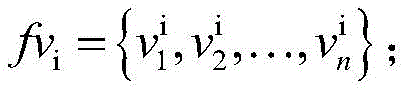
Each image of (a) appears through words in the feature dictionaryN-dimensional eigenvector { v } consisting of probability histograms
1 ,v
2 ,…v
n Characterization, i.e. image I
i (I
i Any image in a multi-angle road roller training sample library) is represented as:
assume that the target picture is I t The target tracking and identifying result is a single road roller, I t The main elements of the method are the road roller and soil background, and other interference factors are not too much, so that the angle characteristics of the road roller can be effectively represented by using a BOF characteristic dictionary method, and the angle of the road roller in each image frame can be effectively identified.
S03, utilizing the matched correlation filter parameter learning of the BOF characteristic to judge the angle class of the target vehicle, as shown in FIG. 5, specifically comprising:
s301, extracting a BOF feature vector of a target image to be identified;
for target image I t According to the known feature dictionary word 1 ,word 2 ,…word n Computing target picture I t The occurrence frequency vector of each word in the feature dictionary is taken as the corresponding BOF feature vector, I t Is expressed as:
s302, creating a DCF related filter model F by using the BOF feature vector l Performing adaptive learning of matched correlation filter parameters on the target image to be identified;
obtaining a BOF feature vector fv of the target image to be identified according to the feature dictionary t Then, the parameters of the relevant filter are learned by combining the initial parameters of the DCF filter, wherein the parameters comprise the target image I t Angle characteristics of the road roller.
The target image I to be identified
t N-dimensional BOF feature vector fv of (2)
t Corresponding filter F
l N parameters { f }
1 ,f
2 ,…,f
n By minimizing the actual correlation response
The mean square error with the ideal correlation response d. The mean square error calculation formula is as follows:
in equation (2), the second term addend is regularization of the filter parameters with a weight ε. The generally ideal correlation response output is a gaussian function parameterizing the standard deviation, so the gaussian filter is set when initializing the filter parameters.
Equation (2) is a typical linear least squares problem, and the filter that minimizes the result of equation (2) can be calculated by converting equation (2) to the frequency domain using the Parseval theorem:
Wherein F is
l Is f
l Corresponding discrete Fourier transform, V
l t Is that
Corresponding discrete fourier transform,/->
Complex conjugation was characterized.
Formula (3) characterizes the passage of a single target picture I t Feature vector fv t The result of the filter is learned.
S303, in order to accurately determine the angle of each frame of the target image, the robustness of the correlation filter needs to be ensured, so the embodiment proposes to approximate the filter to the ideal effect based on the adaptive idea, i.e. determine the new frameWhen the angle of the target image is changed, the filter parameters are updated according to the BOF characteristic of the new frame of target image. BOF feature through new frame of target image
Updating the numerator of the filter f>
And denominator D
new The method comprises the following steps:
where ω is the filter update rate parameter, discrete Fourier transform V using the BOF characteristics of the new frame image new In combination with the current filter parameters B now And D now And obtaining filter parameters of a new frame of target image, representing angle information of the road roller in the current frame of image, and better matching pictures in a multi-angle target training sample library to be identified.
S304, using BOF-DCF filter F l Pair I t Is defined by the BOF feature vector fv t Scoring to obtain score y score ;
The known feature dictionary { word }, is known from the above steps
1 ,word
2 ,…word
n Multi-angle target sample training library
Each image in the matching image can be calculated to obtain the frequency histogram of the occurrence of the words in the characteristic dictionary, namely the characteristic vector +.>
Its discrete fourier transform
The angle information of the road roller in the sample training library picture is included. Calculating any image I in target training sample library to be identified
i The discrete fourier transform of the correlation score between the eigenvectors and the filter parameters is: />
Wherein B is now And D now Is based on the image I of the object to be identified i The filter parameter obtained by BOF feature vector calculation of (2) is a constant, and the denominator is not 0.
The result of the calculation is the discrete Fourier transform of the correlation score, in order to obtain the real correlation score, the calculation result is subjected to inverse Fourier transform, and the real part is recorded as any image I in the multi-angle target sample training library i And the current target picture I to be identified t Is a related score of (2):
s305, according to the score y score And judging whether the engineering vehicle angle in the target image is of type I or type II.
Because the roller is located front and back, the image color is comparatively single, possess less fine structure than the side. The side road roller has more yellow areas, so the embodiment refers to a type I angle road roller when the road roller is positioned on the front side and the back side, and refers to a type II angle road roller when the road roller is positioned on the front side, the side and the back side.
Image I in training library for obtaining multi-angle target samples i And the current target picture I to be identified t After the correlation score of (2), the sample image with the highest correlation score is considered as the object with the best matching target picture, and the angle label of the object is considered as the target picture I t And the angle of the road roller. If the angle automatic detection result is I-type angle, outputting a pictureAnd I', outputting a picture I if the angle automatic detection result is a II-type angle.
And the angle class of the road roller in the target image frame is finished, and corresponding subsequent processing is carried out according to the angle class.
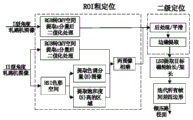
S04, performing coarse positioning and secondary positioning on the ROI area of the target road roller according to the angle category of the target, and obtaining the contour of the road roller.
The angle of the road roller in the target image frame can be judged to be I type or II type by the steps, and the two types of angles have different positions and shape characteristics, so that the two types of image frames need to be further processed respectively, as shown in fig. 6.
S401, roughly positioning the road roller according to the angle category of the road roller to obtain a region of interest (ROI) of the road roller in a target image frame;
(a) If it is determined that the type I angle road roller is an angle road roller, since the background such as the road roller and the land is difficult to distinguish in the commonly used HSI color space, fig. 7 (a) is a gray histogram of the road roller, and there are multiple peaks with smaller distinguishing degree; whereas the C component histogram in the CMY color space has a distinct double peak, which can better distinguish the road roller from the background, as shown in fig. 7 (b).
Thus, the target image I is first t Conversion to CMY color space is performed according to the following conversion formula:
further extracting C-component gray scale image I 'in CMY color space' c As shown in fig. 8 (a) which is an original image of the road roller, fig. 8 (b) which is a C-component gray scale image; then to I' c And (3) performing Otsu automatic threshold segmentation algorithm to calculate an adaptive threshold, so that the inter-class variance of the foreground and the background in the image is maximum and the intra-class variance is minimum. As shown in FIG. 8 (c), the ROI (region of interest) of the I-type angle road roller is obtained by segmenting the ROI (region of interest) by a coarse positioning algorithm' bw 。
(b) If the type II angle road roller is judged, compared with the type I angle road roller image, the yellow area of the type II angle road roller image is large and the detail structure is more. The ROI coarse positioning algorithm for type ii angle rollers should therefore use the hue components to extract the yellow region in the HSI color space and the C component in the CMY color space to make the roller more distinguishable from the background and further process it using the Otsu algorithm, as shown in fig. 9.
First, the type II angle road roller image I 'is converted into HIS color space, and the saturation component image I' is known from FIG. 9 (b) " s The boundary of the middle road roller is obvious, and the gap between the background and the road roller is larger. Extracting a region with higher saturation of the road roller by using an Otsu algorithm to obtain effective segmentation I' of the bottom region of the road roller " s-bw . Due to the tone image I' of FIG. 9 (a) " H The medium land is different from the yellow of the road roller, so in order to further extract the yellow region of the road roller, the color tone range of the yellow of the road roller in the color tone component is segmented and extracted to obtain I', and the yellow region of the road roller is extracted " H-bw The interference of the ground to the ROI area extraction algorithm is effectively avoided, as shown in fig. 9 (c). Finally, the color tone I' H-bw Saturation I' s-bw Binary image I 'of C component in CMY color space and binary image I' of C component in CMY color space " C-bw Obtaining the ROI area extraction I' of the road roller profile in FIG. 9 (f) by summing " bw
S402, performing secondary positioning on the ROI of the road roller in the image frame based on morphology and DOG operators to obtain the contour of the road roller;
s4021, filling holes in ROI (region of interest) of the road roller to obtain I k ;
To better extract the roller wheel axle length/frame length, the resulting roller ROI image I is required bw (I bw Representing the ROI area I 'of the I-type angle road roller' bw Or the ROI area I' of the II-type angle road roller " bw The image) to remove the influence of interference items such as background on the segmentation result. After the ROI rough positioning is carried out on the road roller image, the ROI image I bw The part of the position of the cockpit is missing, so that the part of the missing position is filled by hole filling, and the formula is as follows:
Wherein B is a 3×3 symmetrical structural element, its central element is 1, and the rest is 0; i bw Representing the ROI image of the road roller, I k Is associated with the ROI area I of the road roller bw Arrays of the same size, I 0 Is an all 0 matrix, I k Is the currently filled array of holes. After one point in each hole is given, iteratively filling all holes with formula (9), when I k =I k-1 The algorithm ends at the k-th step of iteration; i k And B contains all filled holes and their boundaries, the filled image is as in FIG. 10 (a).
S4022, removing the isolated small-area object, and obtaining an image I k Removing non-road roller areas such as land and sundries mixed in the road to obtain more accurate contour images to obtain I e As shown in fig. 10 (b);
s4023, median filtering is adopted to the image I e Smoothing to obtain image I f The formula is as follows:
wherein x and y are respectively the images I f As shown in fig. 10 (c), median filtering can attenuate road roller image I f The influence of noise in the linear detection on the linear detection is ensured, and the effectiveness and reliability of the linear detection are ensured.
S3024, utilizing a DoG operator to image I of the road roller f And (5) automatically extracting edges. DoG operator has small calculation complexity, accurate edge extraction and strong noise resistance, and the operator is used for image I f And performing two different Gaussian conversions and performing differential operation, wherein the mathematical expression is as follows:
wherein M, N, sigma 1 、σ 2 Is a parameter of the DoG operator, and x and y are respectively the abscissa and the ordinate of the DoG operator. The obtained DoG operator and the image I m Convolution to obtain the automatic segmentation I of the road roller profile DoG As shown in fig. 10 (d). FIG. 10 (e) shows the extracted contour I DoG And (5) performing the effect after superposition on the original image of the road roller.
S05, automatically detecting and extracting a roller shaft length/frame length straight line of the road roller from the road roller profile;
as shown in fig. 11, when the road roller is at the front, front side and side, extracting the axial length of the front grinding wheel of the road roller as the rolling length of the road roller; when the road roller is positioned on the back side and the back surface, the axial length of the grinding wheel is shielded by the vehicle body, so that the rear frame length of the road roller is detected as the rolling length of the road roller.
As shown in fig. 12, a flowchart for extracting the axle length/frame length detection of a grinding wheel from a road roller profile includes the steps of:
s501, regarding contour image I DoG Gradient calculation and pseudo-sequencing are carried out: first, using (12) to map road roller profile I DoG Each pixel point I of (1) DoG The four pixels at the bottom right of (x, y) perform gradient calculations to find where there may be line segment edges. Wherein the formula (13) and the formula (14) are respectively pixel points I DoG (x, y) first order differentiation in the x, y direction. Then the gradient values are ordered to a certain degree according to the distribution of the gradient values, and the pseudo ordering shortens the time to O (n) linear time.
S502, dividing a horizontal line field to obtain an LSR region, wherein the vertical direction angle of each pixel gradient is the horizontal line angle of the pixel, and the LSR region can be obtained by using the formula (15):
the horizontal line angles of all the points form a horizontal line field, the horizontal line field is cut into a plurality of connected domains according to the horizontal line angles by using a region growing method, the horizontal line angle change of all the pixel points in each connected domain cannot exceed a tolerance value tau, the connected domains are called line support regions, and each line support region is a candidate region of the axial length/the frame length of a grinding wheel.
The method for growing the region comprises the steps of using a point with large gradient amplitude in a sequencing list obtained by pseudo sequencing as a seed point, and using the horizontal line angle of the point as the initial angle theta of the region region Then find the sum θ in eight neighborhoods region A point whose deviation is less than the tolerance value τ is then added to the region and updated, with the updated calculation formula as follows:
where j represents the index of pixel points traversed, when the sum θ is not satisfied in the octal neighborhood of all points in the region region When the deviation of (2) is smaller than the tolerance value tau, stopping growth. The error tolerance value τdefault is set to 22.5, and the error tolerance is 45 degrees for the entire region rectangle. Since pixels with small gradient values correspond to smooth or slowly varying regions of the image, which would cause larger gradient calculation errors when quantized, it is necessary to set gradient thresholds such that points with gradient values smaller than the gradient threshold are not used in LSR.
S503, performing rectangle verification on the LSR area: rectangular verification of LSR using the Contrario method and Helmholtz rule is required to obtain a more accurate and smaller area where the possible mill wheel axle length/frame length is located. Pair I DoG The LSD test results of (a) are shown in fig. 13 (a), and the axle length/frame length of the mill wheel can be selected according to actual requirements.
S504, screening the shaft length/frame length of the target grinding wheel. In this embodiment, in order to quickly screen the target cross bar line, we first perform initial positioning on the cross bar position, and because the cross bar position is located at the lower position of the road roller, select the lower 1/2 portion of the image of the road roller to extract the line structure. Then there are different cross bar constraints for different angle road rollers:
the constraint conditions of the front and back cross bars are as follows: the absolute value of the straight line angle should be within + -20 DEG, and the straight line length is greater than 1/2 of the picture width. Fig. 13 (b) is the final screened crossbar result.
The side/front/rear rail constraints are: the absolute value of the straight line angle should be within + -10 DEG, and the straight line length is greater than 1/2 of the picture width.
And judging the possible axle length/frame length of the initially positioned grinding wheel by using the constraint conditions, and finally obtaining the axle length/frame length of the grinding wheel with different angles and identifying the inclined rolling surface.
S06, automatically detecting the track surface according to the extracted straight line of the axial length/the frame length of the grinding wheel to obtain the tilting track surface of the target construction vehicle.
S601, automatically extracting the shaft length/frame length of a grinding wheel for a current frame image and a next frame image;
s602, connecting two ends of a rolling wheel axial length/frame length straight line detected in two adjacent frames of images to form an inter-frame difference quadrilateral, wherein the quadrilateral is a tilting path surface of a road roller in two adjacent frames; straight line a connected by broken lines in fig. 14 1 A 2 And B 1 B 2 Forming an inter-frame difference quadrangle A 1 A 2 B 2 B 1 The quadrangle is the tilting path surface of the road roller in two adjacent frames.
S603, overlapping the frame difference quadrilaterals of all adjacent two frames in the target video, so as to show the complete rolling track surface of the road roller in the video, wherein as shown in FIG. 15, the arrow tracks in the diagrams (a) - (d) are all the rolling track surfaces of the road roller with different angles, which are extracted in the embodiment, from (a) front surface, (b) front side surface, (c) side surface, and (d) back side surface to back surface.
Example 2
The embodiment is a multi-angle discrimination-based automatic detection device for a rolling track surface, which is characterized by being a detection device formed by module units corresponding to the steps of the automatic detection method for the rolling track surface in any embodiment, and is used for automatically detecting the rolling track surface of a construction vehicle.
Example 3
In order to better illustrate the excellent effects provided by the scheme provided by the invention, the present example is illustrated by experimental test results. The experimental video data are obtained by aerial photographing of a large-scale unmanned aerial vehicle on a national power grid construction site at a height of 30 meters. The unmanned aerial vehicle collects video formats to be mp4, 15 sections of construction site videos are collected altogether, the average duration of the videos is 70 seconds, the video resolution is 1080P, namely, picture pixels are 1920 x 1080, the frame rate is 25, and the total frames of images are 10629 frames.
The relative positions of the unmanned aerial vehicle and the road roller in the video are random, the video contains 1-3 different construction vehicle types, the road roller profile is complete, and the complete road roller driving process is contained.
1. Road roller angle discrimination experimental result
The BOF characteristic of the image characterizes the regional characteristic information of the image, covers the angle information of the road roller, and can accurately identify the angle information of the road roller in the target image through the matched relevant filter response of the reference picture in the multi-angle road roller sample training library. The result of identifying the angle of the road roller in the video shot by the unmanned aerial vehicle by applying the matching algorithm is shown in fig. 16, and the result of identifying the angle of the video of the whole road roller is shown in fig. 17.
In fig. 17, the abscissa indicates the number of video frames, and the ordinate indicates the result of the quantification of the angle of the road roller, and the values of "front", "side", "back" and "side" of the road roller correspond to the values of 2, 1.5, 1, 0.5 and 0, respectively. As can be seen from the figure, the recognition accuracy is higher when only a single angle exists in the video of the road roller, but the accuracy is reduced if the angle is changed. Because the road roller has slower running speed, the offset between adjacent frames is not large, so that the actual angle of the road roller is difficult to judge at the critical position of two angles, and the picture with the error angle judgment appears.
2. Road roller angle discrimination contrast experimental analysis
Image matching can be realized by performing correlation filtering through different features, typical image features comprise a direction gradient histogram (Histogram of Oriented Gridients, HOG) feature, a contour (Outline) feature and the like, the embodiment adopts 7 segments of videos to compare the features with matching correlation filtering to realize road roller angle identification effect and BOF-MCF-based angle identification effect, and the 7 segments of videos comprise angle information as follows: "front side", "front side-front side", "front side-side", "front side", "back side-back", "back side", "side", the results are shown in table 1:
Table 1 comparison of MCF road roller angle identification effects based on different features
The visual results of table 1 are shown in fig. 18.
As can be seen from comparing the results of Table 1, the matched correlation filter based on the BOF features can accurately and efficiently identify the angle information of the road roller, and the angle identification accuracy is over 90 percent. The recognition accuracy of the three types of single angles of the front side, the front side and the back side is high, and the recognition rate of the side and the angle change is reduced, because the angle difference between the frames of the road roller in the video is small, and the slight deviation of the relative positions of the unmanned aerial vehicle and the road roller can cause the error of judging the angle of the road roller.
The BOF characteristic of the road roller image is a characteristic word occurrence frequency histogram calculated based on a matching image library, even if the sizes of the images are different, the characteristic vector with the same dimension can be obtained, so that the BOF characteristic can better represent the characteristic of the color image without any processing of the image, and basically no information is lost. The dimensions of the HOG feature and the contour feature vector are related to the size of the picture, and the dimensions of input parameters for performing matched related filtering are consistent, so that the picture of the road roller needs to be subjected to size adjustment before the two types of feature vectors are calculated, the size adjustment processing involves image downsampling or interpolation, the image information of the road roller is partially lost or modified, the angle information of the road roller is incomplete, and the angle identification accuracy is low.
3. Test results and analysis of axial length/frame length of grinding wheel
In order to analyze the detection effect of the axle length/frame length of the roller and the detection performance of the rolling path surface of the roller, the test is manually calibrated once every 10 frames, wherein the test comprises the axle length of the roller with 78 frames on the front side, the axle length of the roller with 46 frames on the front side, the axle length of the roller with 25 frames on the side, the frame length of the roller with 50 frames on the rear side and the frame length with 80 frames on the back side.
In the scheme of the invention, LSD is utilized to detect the length of the grinding wheel shaft/the length of the frame, and in order to analyze the detection effect of the LSD, the experiment is analyzed through the absolute angle difference delta theta between the standard length of the grinding wheel shaft/the length of the frame and the detected length of the grinding wheel shaft/the length of the frame. Wherein the absolute angle difference Δθ is defined as follows:
assume that the coordinates of two end points of the shaft length/frame length of a standard grinding wheel are respectively A 1 (x 1 ,y 1 )、B 1 (x 2 ,y 2 ) Two end point coordinates of the axial length/the frame length of a grinding wheel detected by an LGC algorithm are respectively A 2 (x 3 ,y 3 )、B 2 (x 4 ,y 4 ) The following steps are:
according to equation (17), the absolute angle differences Δθ of five angles of the road roller are calculated in this experiment. The absolute angle difference delta theta of five angles of the road roller is shown in table 2.
Table 2 the duty cycle of the absolute angle difference delta theta of five angles of the road roller
| Angle of
|
Front face
|
Back surface
|
Front side surface
|
Rear side surface
|
Side surface
|
| Δθ≤2°
|
97.44%
|
11.25%
|
65.22%
|
16.00%
|
16.00%
|
| 2°<Δθ≤5°
|
2.56%
|
81.25%
|
32.61%
|
76.00%
|
60.00%
|
| 5°<Δθ≤10°
|
0.00%
|
7.50%
|
2.17%
|
12.00%
|
24.00% |
As can be seen from Table 2, the absolute angle difference delta theta between the standard wheel axle length/frame length and the detected wheel axle length/frame length is mainly distributed in the range of 0-5 degrees, the absolute angle delta theta difference is smaller in range, the LSD detection effect is better, and the method has practical significance and is suitable for detecting the wheel axle length/frame length of the road roller.
4. Detection result and analysis of tilting path surface of road roller
In order to evaluate the detection performance of the road roller tilting road surface, the method provided by the invention uses the Dice coefficient (The Dice Similarity Coefficient), the over-recognition rate and the under-recognition rate as indexes for evaluating the recognition result of the road surface. The method uses the Dice coefficient as the measurement of the overlapping part of the road roller path surface extracted by the algorithm and manually marked, and represents the similarity between the extracted tilting path surface result and the manually marked result, and the calculation formula is shown as formula (18):
t in (18) S R is a set of road roller rolling path surfaces for providing algorithm output S Is a manually marked set of reference path facets.
Over-recognition rate: namely, the duty ratio of the pixel points of the identification result outside the reference path surface of the manual mark is shown in the formula (19):
In the formula (19), O S The number of pixels that are not included in the reference path surface result in the identification result is represented. The larger the OSR value, the more severe the algorithm over-recognition proposed by the present study.
Rate of undersign: namely, the duty ratio of the pixel points lacking in the recognition result in the reference path plane is expressed as the formula (20):
in the formula (20), U S The number of pixels which are not included in the recognition result of the research algorithm in the reference path surface result is represented, and the greater the USR value is, the more serious the detection result of the research proposed algorithm is in the lack of recognition. Table 3 shows the results of the Dice coefficient, the over-recognition rate, and the under-recognition rate of the test results of this example. As can be seen from the parameters in Table 3, the DSC parameters of the algorithm provided by the invention are within the range of 83.00% -92.72%, which shows that the similarity between the road surface identification result and the manual marking reference result is high, and the over-identification rate and the under-identification rate are lower, so that the error of the result obtained by the algorithm is smaller, and the algorithm is suitable for the automatic detection of the road surface tilting of the road roller at different angles.
Table 3 presents the results of the performance analysis of the algorithm
The invention provides a construction vehicle track area analysis scheme based on multi-angle discrimination aiming at the track area measurement aspect of a construction vehicle. Firstly, determining a target vehicle in a first frame image, tracking the target vehicle by means of Mean-Shift target tracking, and outputting the position of the target vehicle; secondly, learning and automatically identifying angle information of the road roller based on the BOF-MCF characteristic parameters provided by the invention; and then, based on the road rollers with different angles, providing different track surface detection methods, and connecting the track surfaces of the road rollers with different angles to finally obtain the tilting track surface of the construction vehicle.
The feasibility of the whole set of measurement scheme of the track area of the construction vehicle is high: firstly, based on the actual condition of the actual construction vehicle running track, the BOF-MCF characteristic parameters are provided to identify the angle information of the road roller, the construction vehicles with different angles call different track area detection schemes, the measurement is accurate, and the applicability is high; secondly, in the track surface measurement, the whole construction vehicle is replaced by the length of the wheel shaft/the length of the frame, the identification efficiency of the whole project road roller is improved while the construction vehicle can be represented, and the error between the final track surface identification result and the manual marking reference result is small, so that the track surface measurement method is suitable for the track surface measurement of the construction vehicle.
The construction vehicle can be effectively tracked, the running track area of the construction vehicle is obtained, the construction site tilting condition can be monitored in real time, and the management and control efficiency of the construction site is improved.
All of the features disclosed in this specification, or all of the steps in a method or process disclosed, may be combined in any combination, except for mutually exclusive features and/or steps.
The invention is not limited to the specific embodiments described above. The invention extends to any novel one, or any novel combination, of the features disclosed in this specification, as well as to any novel one, or any novel combination, of the steps of the method or process disclosed.