Disclosure of Invention
Aiming at the problems, the invention aims to solve the problems that the existing equipment is single in conveying vehicle type, needs to load workpieces manually and is low in efficiency.
The invention is realized by adopting the following technical scheme:
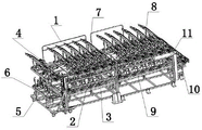
a low-consumption high-efficiency multi-vehicle threshold front conveying device comprises: the device comprises a sliding transfer frame 1, an upper layer slideway 2, a lower layer slideway 3, a logistics elevator 4, a tray 5, a tray support 6, a feeding port frame 7, a feeding port upper layer slideway 8, a feeding port lower layer slideway 9, a bracket I10 and a locking mechanism 11, wherein a first connecting seat 203 in the upper layer slideway 2 is matched with a guide rod 102 on the upper side in the sliding transfer frame 1, a connecting seat I307 in the lower layer slideway 3 is matched with a guide rod 102 on the lower side in the sliding transfer frame 1, a locking handle 107 in the sliding transfer frame 1 is matched and locked with a locking hanging block I419 in the logistics elevator 4, after the tray 5 is loaded, the tray is slid on a first triangular iron 205, an iron I301, a triangular iron II 603, a triangular iron III 801, a triangular iron IV 901 and a triangular iron 1011 through a guide wheel 507, a connecting head 604 and a first connecting plate 605 in the tray support 6 are connected with a first chain 404 and a sliding block 416 in the logistics elevator 4 through bolts, the guide rod 102 on the upper side in the feeding port frame 7 is matched with the first connecting seat 203 in the feeding port upper layer slide way 8, the guide rod 102 on the lower side in the feeding port frame 7 is matched with the first connecting seat 203 in the feeding port lower layer slide way 9, the connecting plate II 1002 in the bracket I10 is connected with the connecting plate I705 in the feeding port frame 7 through bolts, the L-shaped connecting block 1103 in the locking mechanism 11 is connected with the bracket upper frame 1001 in the bracket I10 through bolts, the locking handle 107 in the feeding port frame 7 is matched with the first locking hanging block 105 in the sliding transfer frame 1, so that the connected frames are fixed together, and the conveying of parts is facilitated.
When conveying parts, firstly, the slippage transfer frame 1 is butted with the logistics elevator 4, the tray bracket 6 falls to an initial position, and the L rod 408 (the rod 303, the connecting lug seat 305, the stop rod 306 and the L rod 408 form a four-link limiting device) of the lower layer slideway 3 of the slippage transfer frame 1 is collided, so that the first empty tray 5 on the lower layer slides to the tray bracket 6 through gravity, and the second empty tray 5 is limited and fixed. Manually placing the front workpieces of the doorsills of different vehicle types on the tray 5, then pressing the lifting button, and lifting the tray bracket 6 to the workpiece loading position. The pallet 5 then slides with the work pieces, also against gravity, onto the upper ramp 2 of the transfer trolley. The tape pallet 5 is automatically restrained due to the presence of the gravity check device 204 at the end of the chute.
When the empty pallets 5 on the lower layer slideway 3 are all full of pieces and are lifted to the upper layer slideway 2 of the transfer trolley by the logistics elevator 4, the transfer trolley (the sliding transfer frame 1, the upper layer slideway 2, the lower layer slideway 3 and the pallets 5 filled with the pieces form the transfer trolley, for convenience of describing the working principle, the empty pallets 5 are not arranged on the lower layer slideway 3 and the upper layer slideway 2) can be transferred to a feeding port for loading pieces by material flow, because the transfer trolley slideway has an inclination angle, in order to prevent the pallets 5 from sliding out of the transfer trolley, a first gravity limiting device 204 (without a power source) is added at the front end of the upper layer slideway 2, the pallets 5 are prevented from sliding out in the transfer trolley transportation process, and a first gravity non-return device 202 is added at the rear end of the upper layer slideway 2 and the front end of the lower layer slideway 3.
After the transfer vehicle reaches the material port, the transfer vehicle is accurately butted with a material port frame 7, and is locked with a first locking hanging block 105 in a sliding transfer frame 1 through a locking handle 107 in the material port frame 7, after the butting is completed, a first gravity limiting device 204 in an upper layer slide way 2 just touches an unlocking block I804 in an upper layer slide way 8 of the material port to automatically unlock, a tray 5 with a piece slides to a buffer area of the upper layer slide way 8 of the material port through gravity, meanwhile, a gravity limiting device I903 in a buffer area of a lower layer slide way 9 of the material port touches a first unlocking block 302 in a lower layer slide way 3 to automatically unlock, an empty tray 5 slides to the lower layer slide way 3 of the transfer vehicle through gravity, and is limited through a four-bar limiting device (a bar 303, a connecting lug seat 305, a blocking bar 306 and an L bar 408 form the four-bar limiting device).
The first cylinder 712 in the bracket I10 drives to rise, the two blocking cylinders 805 on the right side of the upper slide 8 of the feeding port are opened, the tray 5 automatically slides to the bracket I10, the tray 5 is positioned and clamped through the stop block II 1012, the cylinder positioning pin 1009 and the locking mechanism 11, and the bracket I10 falls to the robot grabbing position to wait for taking a workpiece. The photoelectric switch 1013 can detect information of different vehicle types and feed the information back to the control system, so that the robot takes the grippers of different vehicle types to take a part, after the robot takes the part, the clamping mechanism for positioning the tray 5 is opened, and the air cylinder I1008 is turned over to slide the empty tray 4 to the buffer area of the lower layer slide 9 of the feeding port.
The beneficial effects of the invention are as follows: the electric energy-saving device has the advantages of simple structure, convenience in operation, ultrahigh cost performance, saving of electric energy, reduction of cost of operators and improvement of the utilization rate of multiple vehicle types.
The energy-saving mode comprises the following steps: the device uses the self-weight of the part to achieve its function. The sliding of the tray 5 is realized by the gravity of the tray and the inclination angle of the slide way, and the traditional motor driving and air source pushing are replaced; the rear end of the upper layer slideway 2 and the front end of the lower layer slideway 3 of the transfer trolley are respectively provided with a first gravity check device 202 to replace pneumatic limit; the front end of the upper layer slide way 2 of the transfer trolley and the lower layer slide way 9 of the feeding port are provided with gravity limiting devices instead of pneumatic limiting.
The 'consumption reduction': when the equipment is used for loading in a logistics area, the logistics elevator 4 falls once to achieve two purposes, namely, the logistics elevator 4 reaches a loading position, and the four-link limiting device (the rod 303, the connecting lug seat 305, the stop rod 306 and the L rod 408 form the four-link limiting device) of the lower-layer slideway 3 is unlocked, so that the first empty tray 5 is moved to the logistics elevator 4, and the second empty tray 5 is fixed at the original position. The use efficiency of the motor is improved, and new energy consumption is avoided.
The 'cost reduction': before the equipment is added, the process of the station is that an operator manually loads parts on the material opening, the workpiece is manually loaded for 10s, the robot takes 90s for welding, namely, the operator needs to wait for 80s for each workpiece, and great personnel safety risks exist.
The 'effect improvement': this equipment has made the feeding system of standard, can realize the use of unlimited motorcycle type, only needs to do corresponding tray 5 according to tray 5's standard size, replaces tray 5 in batches and realizes the location of different motorcycle type product spare, great improvement production efficiency, specifically as follows:
one set of device can realize the sharing of infinite vehicle types;
the use of unlimited vehicle types is realized in one space;
the use of unlimited vehicle types is realized by one-time investment;
because the tray 5 can be shared by multiple vehicle types, the equipment can be produced by mixed flow of multiple vehicle types.
Detailed Description
1. Referring to fig. 1, 2, 3, 4, 5, 6, 7, 8, 9, 10, 11, 12, 13, 14, 15 and 16, a low-consumption high-efficiency multi-vehicle threshold front conveying apparatus according to the present embodiment includes: the device comprises a sliding transfer frame 1, an upper layer slideway 2, a lower layer slideway 3, a logistics elevator 4, a tray 5, a tray support 6, a feeding port frame 7, a feeding port upper layer slideway 8, a feeding port lower layer slideway 9, a bracket I10 and a locking mechanism 11, wherein a first connecting seat 203 in the upper layer slideway 2 is matched with a guide rod 102 on the upper side in the sliding transfer frame 1, a connecting seat I307 in the lower layer slideway 3 is matched with a guide rod 102 on the lower side in the sliding transfer frame 1, a locking handle 107 in the sliding transfer frame 1 is matched and locked with a locking hanging block I419 in the logistics elevator 4, after the tray 5 is loaded, the tray is slid on a first triangular iron 205, an iron I301, a triangular iron II 603, a triangular iron III 801, a triangular iron IV 901 and a triangular iron 1011 through a guide wheel 507, a connecting head 604 and a first connecting plate 605 in the tray support 6 are connected with a first chain 404 and a sliding block 416 in the logistics elevator 4 through bolts, the guide rod 102 on the upper side in the feeding port frame 7 is matched with the first connecting seat 203 in the feeding port upper layer slide way 8, the guide rod 102 on the lower side in the feeding port frame 7 is matched with the first connecting seat 203 in the feeding port lower layer slide way 9, the connecting plate II 1002 in the bracket I10 is connected with the connecting plate I705 in the feeding port frame 7 through bolts, the L-shaped connecting block 1103 in the locking mechanism 11 is connected with the bracket upper frame 1001 in the bracket I10 through bolts, the locking handle 107 in the feeding port frame 7 is matched with the first locking hanging block 105 in the sliding transfer frame 1, so that the connected frames are fixed together, and the conveying of parts is facilitated.
2. Referring to fig. 2, the slippage transfer frame 1 is composed of a first guardrail 101, a guide rod 102, a first vertical beam 103, a hook 104, a first dead-lock hanging block 105, a first universal wheel 106, a dead-lock handle 107, a single lug seat 108, a first cross beam 109 and a middle beam 110, wherein the first guardrail 101 is connected with the first cross beam 109 through bolts, the guide rod 102 is connected with the first cross beam 109 through bolts, the first vertical beam 103 is connected with the first cross beam 109 through welding, the hook 104 is connected with the middle beam 110 through welding, the first dead-lock hanging block 105 is connected with the first vertical beam 103 through welding, the first universal wheel 106 is connected with the first cross beam 109 through bolts, the dead-lock handle 107 is connected with the first cross beam 109 through welding, the single lug seat 108 is connected with the middle beam 110 through welding, and the first cross beam 109 is connected with the middle beam 110 through welding.
2. Referring to fig. 3, the upper layer slideway 2 is composed of an upper layer slideway frame 201, a first gravity check device 202, a first connecting seat 203, a first gravity limiting device 204 and a first triangular iron 205, wherein the first gravity check device 202 is connected with the upper layer slideway frame 201 by welding, the first connecting seat 203 is connected with the upper layer slideway frame 201 by welding, the first gravity limiting device 204 is connected with the upper layer slideway frame 201 by welding, the first triangular iron 205 is connected with the upper layer slideway frame 201 by welding, and a counterweight nut is arranged at the right end (in the position in the figure) of the first gravity limiting device 204, so that the left end of the first gravity limiting device 204 is always tilted to play a limiting role.
3. Referring to fig. 4, the lower-layer slideway 3 is composed of a triangular iron i 301, a first unlocking block 302, a rod 303, a spring 304, a connecting lug seat 305, a stop rod 306, a connecting seat i 307, an L rod 308 and a lower-layer slideway frame 309, wherein the triangular iron i 301 is connected with the lower-layer slideway frame 309 through welding, the first unlocking block 302 and the connecting seat i 307 are connected with the lower-layer slideway frame 309 through welding, the rod 303 is fixedly connected with the spring 304, the rod 303 is connected with the L rod 308 through a pin shaft, the connecting lug seat 305 is connected with the lower-layer slideway frame 309 through welding, the stop rod 306 is respectively connected with the rod 303 and the connecting lug seat 305 through a pin shaft, the connecting lug seat 305 is connected with the lower-layer slideway frame 309 through welding, the other end of the spring 304 is fixedly connected with the single lug seat 108 in the sliding frame 1, when the tray bracket 6 moves downwards, a press block 606 just presses the foremost end (rightmost right side in the drawing) of the L rod 308 and then turns up the rod 303, the stopper rod 306 rotates clockwise (with the pin shafts of the rod 303 and the stopper rod 306 as the axis), and the pallet 5 slides onto the pallet bracket 6 by gravity.
4. Referring to fig. 5 and 6, the material flow elevator 4 is composed of a universal wheel i 401, a bottom frame 402, a tripod 403, a first chain 404, a top sprocket 405, a sprocket support 406, a stop block 407, a guide rail 408, a vertical column 409, an intermediate support beam 410, a protective cover 411, a large plate 412, a guide plate 413, a support frame 414, a cushion block 415, a slide block 416, a bearing block 417, a dual output motor 418, a locking hanging block i 419 and a shaft 420, wherein the universal wheel i 401 is connected with the bottom frame 402 through a bolt, the tripod 403 is connected with the bottom frame 402 and the large plate 412 through a bolt, the first chain 404 is engaged with the top sprocket 405, the top sprocket 405 is connected with the sprocket support 406 through a bearing, the sprocket support 406 and the stop block 407 are connected with the large plate 412 through a bolt, the guide rail 408 is connected with the large plate 412 through a bolt, the vertical column is connected with the large plate 412 through a bolt, the intermediate support beam 410 is connected with the vertical column 409 through a welding, the protective cover 411 is connected with the large plate 412 through a bolt, the guide plate 413 is connected with the bottom frame 402 in a welded mode, the support frame 414 is connected with the bottom frame 402 in a welded mode, the cushion block 415 is connected with the support frame 414 through bolts, the sliding block 416 is matched with the guide rail 408, the bearing seat 417 is connected with the large plate 412 through bolts, the double-output motor 418 is connected with the large plate 412 through bolts, the shaft 420 is connected with the double-output motor 418 through a key, the other end of the shaft 420 is connected with a chain wheel through a key, the bearing seat 417 plays a supporting role, the locking hanging block I419 is connected with the upright 409 through a welded mode, and when the tray bracket 6 is driven by the double-output motor 418, the tray bracket 6 descends, falls onto the cushion block 415, meanwhile, the L rod 308 is pressed down to achieve unlocking, the empty tray 5 slides out, and then manual loading is carried out.
5. Referring to fig. 7, the pallet 5 is composed of a pallet frame 501, a first support rod 502, a support rod i 503, a positioning pin 504, a positioning pin support rod 505, a guide wheel seat 506, a guide wheel 507 and a positioning pin plate 508, wherein the first support rod 502, the support rod i 503, the positioning pin support rod 505, the guide wheel seat 506 and the positioning pin plate 508 are connected with the pallet frame 501 through bolts, the positioning pin 504 is fixedly connected with the positioning pin support rod 505, the guide wheel 507 is connected with the guide wheel seat 506 through bolts, the positioning pin 504 is quickly positioned with a pin hole on a workpiece, the positioning pin plate 508 is positioned with a cylinder positioning pin 1009 in the pallet i 10, and then the pallet 5 is clamped through a locking mechanism 11, so that the position of the pallet 5 is prevented from being influenced when the robot grabs the workpiece.
6. Referring to fig. 8, the tray support 6 is composed of a first bracket 601, a first stopper i 602, a triangular iron ii 603, a connector 604, a first connecting plate 605 and a pressing block 606, wherein the first stopper i 602, the triangular iron ii 603 and the pressing block 606 are connected with the first bracket 601 through welding, the first connecting plate 605 is connected with the first bracket 601 through bolts, the connector 604 is connected with the first connecting plate 605 through bolts, and the pressing block 606 presses the L rod 308 to unlock, so that the empty tray 5 slides out.
7. Referring to fig. 9, the loading port frame 7 is composed of a guardrail I701, a longitudinal beam 702, a vertical beam I703, a bottom plate 704, a connecting plate I705, a support 706, a chain I707, a travel switch 708, a chain wheel I709, a chain wheel seat I710, a cross beam I711 and a first air cylinder 712, wherein the guardrail I701 is connected with the cross beam I711 through bolts, the longitudinal beam 702 is connected with the cross beam I711 through welding, the vertical beam I703 is connected with the longitudinal beam 702 and the cross beam I711 through welding, the bottom plate 704 is connected with the cross beam I711 through bolts, the connecting plate I705 is connected with the chain I707 through bolts, the support 706 is connected with the longitudinal beam 702 through welding, the chain I707 is meshed with the chain wheel I709, the travel switch 708 is connected with the vertical beam I703 through bolts, the chain wheel seat I710 is connected with the cross beam I711 through bolts, the first air cylinder 712 is connected with the cross beam I711 through bolts, a cylinder shaft of the first air cylinder 712 is fixedly connected with the chain I707, and the connecting plate I705 is driven to move up and down by the contraction of the air cylinder.
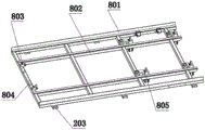
8. Referring to fig. 10, the feeding port upper layer slide way 8 is composed of a triangular iron iii 801, a feeding port upper layer slide way support 802, a gravity check device i 803, an unlocking block i 804 and a blocking cylinder 805, wherein the triangular iron iii 801, the gravity check device i 803 and the unlocking block i 804 are connected with the feeding port upper layer slide way support 802 through welding, the blocking cylinder 805 is connected with the feeding port upper layer slide way support 802 through bolts, when a tray 5 slides onto the feeding port upper layer slide way 8 from the upper layer slide way 2, the two rightmost blocking cylinders 805 are opened (the blocking cylinders 805 extend out) first, after the first tray 5 slides to the position, the two left blocking cylinders 805 are opened first, so that the remaining tray 5 and upper workpieces are blocked on the left side, when a robot is used for loading, the two rightmost blocking cylinders 805 are closed first to slide the tray 5 and upper workpieces onto the bracket i 10, and after loading is finished, the two rightmost blocking cylinders 805 are opened, the two left blocking cylinders 805 are closed again, and the next tray 5 slides in.
9. Referring to fig. 11, the feed opening lower layer slide way 9 is composed of a triangular iron iv 901, a feed opening lower layer slide way frame 902, a gravity limiting device i 903 and a gravity non-return device ii 904, wherein the triangular iron iv 901, the gravity limiting device i 903 and the gravity non-return device ii 904 are connected with the feed opening lower layer slide way frame 902 through welding.
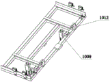
10. Referring to fig. 12, 13 and 14, the bracket i 10 is composed of an upper bracket 1001, a connecting plate ii 1002, a lower bracket 1003, an upper lug 1004, a lower lug 1005, a connecting block 1006, a top rod 1007, a cylinder i 1008, a cylinder positioning pin 1009, a detection switch 1010, a triangle iron v 1011, a stop ii 1012 and a photoelectric switch 1013, wherein the upper bracket 1001 and the lower lug 1005 are connected by bolts, the connecting plate ii 1002 and the lower bracket 1003 are connected by bolts, the upper lug 1004 and the lower bracket 1003 are connected by bolts, the connecting block 1006 and the upper bracket 1001 are connected by bolts, the connecting block 1006 and the top rod 1007 are connected by bolts, the top rod 1007 and the cylinder i 1008 are fixedly connected, the cylinder i 1008 and the lower bracket 1003 are connected by bolts, the cylinder positioning pin and the upper bracket 1001 are connected by bolts, the detection switch 1010 and the upper bracket 1001, the triangle iron v and the upper bracket 1001 are connected by welding, the stop block II 1012 is connected with the bracket upper frame 1001 through a bolt, the photoelectric switch 1013 is connected with the bracket upper frame 1001 through a bolt, the detection switch 1010 is used for detecting whether the tray 5 is in place or not, and the photoelectric switch 1013 is used for detecting information of different vehicle types and feeding the information back to the control system, so that the robot can take the hand grips of different vehicle types to take the workpieces.
11. Referring to fig. 15 and 16, the locking mechanism 11 is composed of an air cylinder ii 1101, a first rod 1102, a connecting block ii 1103, a cushion block ii 1104, a short rod 1105 and a clamping rod 1106, wherein the air cylinder ii 1101 is connected with the first rod 1102 through a pin, the connecting block ii 1103 is connected with the first rod 1102 through a bolt, the cushion block ii 1104 is connected with the connecting block ii 1103 through a bolt, the short rod 1105 is connected with the first rod 1102 through a pin, the short rod 1105 is connected with the clamping rod 1106 through a welding, the air cylinder ii 1101 is connected with the clamping rod 1106 through a pin, fig. 15 shows a clamping state, and the air cylinder contracts to achieve an unlocking state, as shown in fig. 16.
It should be emphasized that the embodiments described herein are illustrative rather than restrictive, and thus the present invention is not limited to the embodiments described in the detailed description, but also includes other embodiments that can be derived from the technical solutions of the present invention by those skilled in the art.