Us application 62/618,054 entitled "three-dimensional display calculated using electromagnetic fields" filed on 2018, month 1, 16, priority under 35u.s.c. § 119. The entire contents of the above application are incorporated herein by reference.
Disclosure of Invention
This disclosure describes methods, apparatuses, devices and systems for using Electromagnetic (EM) field calculations for three-dimensional (3D) displays.
The present disclosure provides techniques that can overcome the limitations present in the known art. As an example, the techniques disclosed herein may be implemented without the use of bulky wearable devices like "3D glasses. As another example, the techniques disclosed herein may be selectively implemented without being limited to: tracking mechanism accuracy, quality of the display device, relatively long processing time and/or relatively high computational requirements, and/or inability to display objects to multiple viewers simultaneously. As another example, the techniques may be implemented without specialized tools and software so that content can be developed that extends beyond and over the tools and software used in conventional 3D content creation. Various embodiments may exhibit one or more of the foregoing advantages. For example, certain embodiments of the present disclosure may produce real-time, full-color, real 3D images that appear to be real 3D objects in the real world and that may be viewed simultaneously by multiple viewers from different points unimpeded.
One aspect of the disclosure features a method that includes: determining, for each of a plurality of elements corresponding to an object in a three-dimensional (3D) space, an electromagnetic field contribution to the element by calculating, in a 3D coordinate system, an electromagnetic field propagation from the element to each of a plurality of elements of a display screen; and for each element of the plurality of elements, generating a sum of electromagnetic field contributions of the plurality of elements to the element.
The electromagnetic field contribution may comprise at least one selected from the group consisting of a phase contribution and an amplitude contribution. The primitives may include at least one selected from the group consisting of point primitives, line primitives, and polygon primitives. The primitives may include line primitives having information including at least one selected from the group consisting of gradient color, textured color, and shading effect. The primitives may also include polygon primitives having information including at least one selected from the group consisting of gradient color, textured color, and shading effect. The plurality of primitives may be indexed in a particular order.
In some implementations, the method further includes obtaining respective primitive data for each primitive of the plurality of primitives. The respective primitive data for each of the plurality of primitives may include respective color information for the primitive, and the determined electromagnetic field contribution to each of the elements includes information corresponding to the respective color information for the primitive. The color information may include at least one selected from the group consisting of a textured color and a gradient color. The respective primitive data for each of the plurality of primitives may include texture information for the primitive. The respective primitive data for each of the plurality of primitives may include shading information on one or more surfaces of the primitive. The shading information may include a modulation of at least one selected from the group consisting of a color on the one or more surfaces of the primitive and a brightness on the one or more surfaces of the primitive.
In some implementations, the respective primitive data for each primitive of the plurality of primitives includes respective coordinate information for the primitive in the 3D coordinate system. The respective coordinate information of each element of the plurality of elements in the 3D coordinate system may be determined based on the respective coordinate information of the plurality of primitives in the 3D coordinate system. The respective coordinate information for each of the elements may correspond to a logical memory address stored in memory for the element.
Determining the electromagnetic field contribution of each of the plurality of elements to each of the plurality of elements may include: determining, in the 3D coordinate system, at least one distance between the element and the primitive based on respective coordinate information of the element and respective coordinate information of the primitive. Determining an electromagnetic field contribution of each of the plurality of elements to each of the plurality of elements comprises: determining a first distance between a first primitive of the plurality of primitives and a first element of the plurality of elements based on respective coordinate information of the first primitive and the respective coordinate information of the first element; and determining a second distance between the first primitive and a second element of the plurality of elements based on the first distance and a distance between the first element and the second element. A distance between the first element and the second element may be predetermined based on a pitch of the plurality of elements of the display screen.
In some examples, at least one primitive of the plurality of primitives is a line primitive including a first endpoint and a second endpoint, and determining at least one distance between the element and the primitive includes: determining a first distance between the element and a first end point of the line primitive; and determining a second distance between the element and a second endpoint of the line primitive. At least one primitive of the plurality of primitives is a triangle primitive including a first endpoint, a second endpoint, and a third endpoint, and determining at least one distance between the element and the primitive comprises: determining a first distance between the element and a first endpoint of the triangle primitive; determining a second distance between the element and a second end of the triangle primitive; and determining a third distance between the element and a third endpoint of the triangle primitive.
In some implementations, determining the electromagnetic field contribution of each of the plurality of elements to each of the plurality of elements includes: determining an electromagnetic field contribution of the element to the element based on a predetermined expression of the element and the at least one distance. The predetermined expression is determined by analytically calculating electromagnetic field propagation from the primitive to the element. The predetermined expression is determined by solving maxwell's equations. The maxwell's equations may be solved by providing boundary conditions defined at the surface of the display screen. The boundary condition may comprise a Dirichlet (Dirichlet) boundary condition or a Cauchy (Cauchy) boundary condition. The plurality of primitives and the plurality of elements may be in the 3D space, and a surface of the display screen may form a part of a boundary surface of the 3D space. The predetermined expression includes at least one selected from the group consisting of a function including a sine function, a function including a cosine function, and a function including an exponential function, and determining the electromagnetic field contribution includes: identifying a value of at least one of the functions in a table stored in memory.
In some implementations, determining an electromagnetic field contribution of each of the plurality of elements to each of the plurality of elements and generating the sum of the electromagnetic field contributions for each of the plurality of elements includes: determining a first electromagnetic field contribution of the plurality of elements to a first element of the plurality of elements and summing the first electromagnetic field contribution for the first element; and determining a second electromagnetic field contribution of the plurality of elements to a second element of the plurality of elements and summing the second electromagnetic field contribution for the second element. Determining the first electromagnetic field contribution of the plurality of elements to the first element may include: determining an electromagnetic field contribution of a first element of the plurality of elements to the first element is performed in parallel with determining an electromagnetic field contribution of a second element of the plurality of elements to the first element.
In some implementations, determining the electromagnetic field contribution of each of the plurality of elements to each of the plurality of elements includes: determining a respective first electromagnetic field contribution of a first element of the plurality of elements to each element of the plurality of elements; and determining a respective second electromagnetic field contribution of a second element of the plurality of elements to each element of the plurality of elements, and generating the electromagnetic field contribution sum for each element of the plurality of elements may comprise: adding the respective second electromagnetic field contribution to the element to the respective first electromagnetic field contribution. Determining the respective first electromagnetic field contribution of the first element to each of the plurality of elements may be performed in parallel with determining the respective second electromagnetic field contribution of the second element to each of the plurality of elements.
Determining the electromagnetic field contribution of each of the plurality of elements to each of the plurality of elements may include: determining a first electromagnetic field contribution of a first element of the plurality of elements to a first element of the plurality of elements is performed in parallel with determining a second electromagnetic field contribution of a second element of the plurality of elements to the first element.
In some embodiments, the method further comprises: for each element of the plurality of elements, generating a respective control signal based on a sum of electromagnetic field contributions of the plurality of elements to the element, the respective control signal for modulating at least one characteristic of the element based on the sum of electromagnetic field contributions of the plurality of elements to the element. The at least one characteristic of the element may include at least one selected from the group consisting of refractive index, amplitude index, birefringence, and retardation. The respective control signal may comprise an electrical signal, an optical signal, a magnetic signal or an acoustic signal. In some cases, the method further comprises: multiplying a scaling factor with the electromagnetic field contribution sum for each of the elements to obtain a scaled electromagnetic field contribution sum, and wherein the respective control signal is generated based on the scaled electromagnetic field contribution sum for the element. The method may further comprise: normalizing the electromagnetic field contribution sum for each of the elements, wherein the respective control signal is based on the normalized electromagnetic field contribution sum for the element. The method may further comprise: sending the respective control signal to the element.
In some embodiments, the method further comprises: sending a control signal to a luminaire, the control signal instructing the luminaire to turn on so that the luminaire emits light onto the display screen. The control signal may be transmitted in response to determining that a sum of electromagnetic field contributions to each of the plurality of elements has been obtained. The modulated elements of the display screen may cause the light to propagate in different directions to form a volumetric light field corresponding to the object in the 3D space. The volumetric light field may correspond to a solution of maxwell's equations with boundary conditions defined by the modulated elements of the display screen. The light may include white light, and the display screen may be configured to diffract the white light into light having different colors.
In some embodiments, the method further comprises: fixed point number representations are used to represent values during computation. Each of the values may be represented as an integer with an implicit scale factor.
In some embodiments, the method further comprises: the mathematical function is performed using a fixed-point number representation. The mathematical function may include at least one selected from the group consisting of sine, cosine, and arc tangent. Performing the mathematical function may include: receiving an expression in a first fixed point format; and outputting a value of a second fixed point format having a different level of precision than the first fixed point format. Performing the mathematical function may include: looking up a table for calculation of the mathematical function, wherein the table comprises at least one selected from the group consisting of a fully enumerated look-up table, an interpolation table, a half-table based polynomial function, and a half-table based full minimum maximum polynomial. Performing the mathematical function may include: application specific range reduction to input. Executing the mathematical function includes: the trigonometric calculation is transformed from the range [ - π, π ] to a signed 2's complementary representation in the range [ -1,1 ].
Another aspect of the disclosure features a method that includes: obtaining primitive data for each of a plurality of primitives corresponding to an object in a three-dimensional (3D) space; calculating a respective first electromagnetic field contribution of a first element of the plurality of elements to each element of a plurality of elements of a display screen; and calculating a respective second electromagnetic field contribution of a second element of the plurality of elements to each element of the plurality of elements of the display screen, wherein calculating the respective first electromagnetic field contribution from the first element is performed at least partially in parallel with calculating the respective second electromagnetic field contribution from the second element.
In some implementations, calculating a first electromagnetic field contribution of the first element to a first element of the plurality of elements is performed in parallel with calculating a second electromagnetic field contribution of a second element of the plurality of elements to the first element. The method may comprise: calculating a respective electromagnetic field contribution of each of the plurality of elements to each of the plurality of elements. The calculation of the respective electromagnetic field contributions may be performed without at least one selected from the group consisting of: extending the object's geometry to the multiple elements, applying visibility tests before packing the wavefront, and decisions or communication between parallel computations for different primitives. Calculating the respective electromagnetic field contribution may be configured to facilitate at least one selected from the group consisting of: adjusting parallel computations for different primitives to achieve speed, cost, size, or energy optimization, reducing latency between initiating rendering and result ready display, increasing precision using fixed-point number representation, and optimizing computation speed by optimizing mathematical functions.
In some embodiments, the method further comprises: fixed point number representations are used to represent values during computation. Representing the value using the fixed-point number representation may be performed without at least one selected from the group consisting of: abnormal floating point for progressive underflow, handling non-numeric values resulting from operations including divide by zero, altering floating point rounding mode, and causing floating point exceptions to the operating system.
In some embodiments, the method further comprises: for each element of the plurality of elements, accumulating electromagnetic field contributions to the element by adding the respective second electromagnetic field contribution to the element to the respective first electromagnetic field contribution to the element.
In some embodiments, the method further comprises: for each element of the plurality of elements, generating a respective control signal based on a sum of electromagnetic field contributions of the plurality of elements to the element, the respective control signal for modulating at least one characteristic of the element based on the sum of electromagnetic field contributions of the plurality of elements to the element.
In some embodiments, the method further comprises: a first primitive adjacent to a second primitive is scaled by a predetermined factor such that reconstruction of the first primitive does not overlap reconstruction of the second primitive. The predetermined factor may be determined based at least in part on a resolution of the display screen. The method may further comprise: obtaining respective primitive data for each primitive of the plurality of primitives, wherein the respective primitive data for each primitive of the plurality of primitives includes respective coordinate information of the primitive in the 3D coordinate system; and determining new respective coordinate information for the first primitive based on the respective coordinate information for the first primitive and the predetermined factor. The method may further comprise: determining an electromagnetic field contribution of the first primitive to each of the plurality of elements based on the new respective coordinate information of the first primitive. The method may further comprise: scaling the second primitive by the predetermined factor. The first primitive and the second primitive may share a common portion, and scaling the first primitive comprises scaling the common portion of the first primitive. Scaling the first primitive may include: scaling the first primitive in a predetermined direction.
Another aspect of the disclosure features a method that includes: obtaining primitive data for each of a plurality of primitives corresponding to an object in a three-dimensional (3D) space; scaling a first primitive adjacent to a second primitive by a predetermined factor using respective primitive data of the first primitive and respective primitive data of the second primitive; and updating corresponding primitive data of the first primitive based on a result of the scaling.
In some implementations, the respective primitive data for each of the plurality of primitives includes respective coordinate information for the primitive in a 3D coordinate system, and updating the respective primitive data includes: determining new respective coordinate information for the first primitive based on the respective coordinate information for the first primitive and the predetermined factor.
In some embodiments, the predetermined factor is determined such that reconstruction of the first primitive does not overlap reconstruction of the second primitive in the 3D space.
In some embodiments, the scaling is performed such that: a gap between reconstructions of the first primitive and the second primitive in the 3D space is large enough to separate the first primitive and the second primitive to minimize an overlap effect, and the gap is small enough to render the reconstructions seamless.
In some implementations, the predetermined factor is determined based at least in part on a resolution of the display screen.
In some embodiments, the method further comprises: storing updated primitive data for the first primitive in a buffer.
In some implementations, the scaling is performed during a rendering process of the object to obtain primitive data for each of the plurality of primitives.
In some embodiments, the method further comprises: sending updated primitive data for the plurality of primitives to a controller, wherein the controller is configured to determine a respective electromagnetic field contribution of each of the plurality of primitives to each of a plurality of elements of a display screen based on the updated primitive data for the plurality of primitives.
In some embodiments, the method further comprises: determining an electromagnetic field contribution of the first primitive to each of a plurality of elements of a display screen based on the updated primitive data of the first primitive.
In some embodiments, the method further comprises: scaling the second primitive by the predetermined factor.
In some implementations, the first primitive and the second primitive share a common portion, and scaling the first primitive includes scaling the common portion of the first primitive.
In some implementations, scaling the first primitive includes: scaling the first primitive in a predetermined direction.
In some implementations, scaling the first primitive includes: scaling a first portion of the first primitive by a first predetermined factor and scaling a second portion of the second primitive by a second predetermined factor, wherein the first predetermined factor is different from the second predetermined factor.
Another aspect of the disclosure features a method that includes: obtaining a plurality of Discrete Cosine Transform (DCT) weights for an image to be mapped onto a specified surface of a particular primitive of a plurality of primitives corresponding to an object in a three-dimensional (3D) space; and determining a respective electromagnetic field contribution of the particular element to each of a plurality of elements of a display screen by taking into account the effect of the plurality of DCT weights of the image.
In some embodiments, the method further comprises: determining a resolution of the image to be mapped onto a specified surface of the particular primitive; and determining the plurality of DCT weights for the image based on the resolution.
In some embodiments, the method further comprises: decoding the DCT weights for the image to obtain a respective DCT amplitude for each pixel of the image.
In some embodiments, the method further comprises: storing values associated with respective DCT magnitudes for pixels of the image along with primitive data for the particular primitive. Determining the respective electromagnetic field contribution may include: calculating a respective electromagnetic field contribution of the particular primitive to each element of the plurality of elements using values associated with respective DCT amplitude values for pixels of the image.
In some embodiments, the method further comprises: selecting specific DCT terms to be included in determining the respective electromagnetic field contributions, each of the specific DCT terms having a respective DCT weight above a predetermined threshold.
Another aspect of the disclosure features a method that includes: obtaining information of a given primitive and an occlusion of the given primitive, wherein the given primitive belongs to one of a plurality of primitives corresponding to an object in a three-dimensional (3D) space; and determining one or more particular elements of the plurality of elements of the display screen that do not contribute to the reconstruction of the given primitive due to the influence of the obstruction.
In some embodiments, the method further comprises: storing information of the particular element and information of the given primitive and the obstruction.
In some implementations, the determining is performed during a rendering process of the object for obtaining primitive data for the plurality of primitives.
In some embodiments, the method further comprises: sending the stored information of the particular element and the information of the given primitive and the obstruction to a controller configured to calculate electromagnetic field contributions of the plurality of primitives to the plurality of elements of the display screen.
In some embodiments, the method further comprises: for each of the particular elements, generating, for each of the particular elements, a sum of electromagnetic field contributions of the plurality of elements to the particular element by excluding the electromagnetic field contribution of the given element to the particular element.
In some embodiments, the method further comprises: for each element of the plurality of elements other than the particular element, generating a sum of respective electromagnetic field contributions of the plurality of elements to the element.
In some embodiments, the method further comprises: masking the contribution of the particular element to the reconstruction of the given primitive.
In some implementations, determining the one or more particular elements includes: connecting the given primitive to an endpoint of the obstruction; extending the connection to the display screen to determine an intersection between the connection and the display screen; and determining elements within a particular range defined by the intersection as the particular elements that do not contribute to the reconstruction of the given primitive due to the influence of the obstruction.
Another aspect of the disclosure features a method that includes: obtaining information of a given primitive and an occlusion of the given primitive, wherein the given primitive belongs to one of a plurality of primitives corresponding to an object in a three-dimensional (3D) space; and for each element of a plurality of elements of a display screen, determining a respective portion of the given cell that does not contribute to the electromagnetic field of the element due to the influence of the obstruction.
In some embodiments, the method further comprises: storing information of the corresponding portion of the given primitive and information of the given primitive and the obstruction.
In some embodiments, the determining is performed during rendering of the object to obtain primitive data for the plurality of primitives.
In some embodiments, the method further comprises: sending the stored information of the corresponding portion of the given primitive and the information of the given primitive and the obstruction to a controller configured to calculate electromagnetic field contributions of the plurality of primitives to the plurality of elements of the display screen.
In some embodiments, the method further comprises: masking electromagnetic field contributions of the respective portion of the given primitive to each of the plurality of elements.
In some embodiments, the method further comprises: for each element of the plurality of elements, generating an electromagnetic field contribution sum of the plurality of elements to the element by excluding an electromagnetic field contribution of the respective portion of the given element to the element. Generating a sum of electromagnetic field contributions of the plurality of primitives to the element may include: subtracting the electromagnetic field contribution of the respective portion of the given element to the element from a sum of electromagnetic field contributions of the plurality of elements to the element without the influence of the obstruction. Generating a sum of electromagnetic field contributions of the plurality of primitives to the element may include: summing electromagnetic field contributions of the element by one or more other portions of the given element, the respective portion and the one or more other portions forming the given element.
In some implementations, determining respective portions of the given element that do not contribute to the electromagnetic field of the element due to the influence of the obstruction includes: connecting the element to an end point of the shade; determining an intersection between the connection and the primitive; and determining a particular portion of the given cell surrounded by the intersection as the corresponding portion of the given cell that does not contribute to the electromagnetic field of the element due to the effect of the obstruction.
Another aspect of the disclosure features a method that includes: obtaining respective primitive data for each primitive of a plurality of primitives corresponding to an object in a three-dimensional (3D) space; obtaining respective geometric specular highlight information for each of the plurality of primitives; and storing the respective geometric specular highlight information and respective primitive data for each primitive of the plurality of primitives.
In some implementations, the respective geometric specular highlight information for each primitive of the plurality of primitives includes: the reflectivity of the surface on which the element is positioned according to the viewing angle.
In some embodiments, the method further comprises: determining a respective electromagnetic field contribution of each of the plurality of elements to each of a plurality of elements of a display screen by considering respective geometric specular highlight information for the element.
Another aspect of the disclosure features a method that includes: obtaining graphics data comprising respective primitive data of a plurality of primitives corresponding to an object in a three-dimensional (3D) space; determining, for each element of the plurality of elements, an electromagnetic field contribution to each element of a plurality of elements of a display screen from the element by calculating the electromagnetic field propagation from the element to the element in a 3D coordinate system; for each element of the plurality of elements, generating a sum of electromagnetic field contributions of the plurality of elements to the element; for each element of the plurality of elements, sending a respective control signal to the element, the control signal for modulating at least one characteristic of the element based on a sum of electromagnetic field contributions to the element; and sending a timing control signal to an illuminator to activate the illuminator to illuminate light on the display screen such that the modulated elements of the display screen cause the light to form a volumetric light field corresponding to the object.
Another aspect of the disclosure features a method that includes: modifying, for each element of a plurality of elements of a display screen, a respective control signal with a predetermined calibration value; applying the modified respective control signal to each of the plurality of elements of the display screen; measuring an output of light incident on the display screen; and evaluating the predetermined calibration value based on the measurement of the light output.
In some embodiments, the predetermined calibration value is the same for each of the plurality of elements.
In some embodiments, the method further comprises: converting, by a digital-to-analog converter (DAC), respective control signals for each of the plurality of elements, wherein altering the control signal for each of the plurality of elements comprises: altering the digital signal of the respective control signal with the predetermined calibration value.
In some embodiments, the predetermined calibration value comprises a plurality of bits.
In some embodiments, the method further comprises: adjusting the predetermined calibration value based on a result of the evaluation. Adjusting the predetermined calibration value may include: modifying one or more values in the plurality of bits. Adjusting the predetermined calibration value may include: determining a combination of values in the plurality of bits based on the predetermined calibration value and another calibration value determined from a previous evaluation.
In some embodiments, the output of the light comprises a phase change of the light or an intensity difference between the output of the light and a background.
In some implementations, the respective control signals of the elements are determined based on a sum of electromagnetic field contributions to the elements by a plurality of primitives corresponding to objects in 3D space.
Another aspect of the disclosure features a method that includes: for each element of a plurality of elements of a display screen, obtaining a respective electromagnetic field contribution sum from a plurality of elements in a three-dimensional (3D) space, the plurality of elements corresponding to an object in the 3D space; applying a respective mathematical transformation to the sum of the respective electromagnetic field contributions to the elements to obtain a sum of transformed respective electromagnetic field contributions to the elements; determining a respective control signal based on a sum of the transformed respective electromagnetic field contributions to the elements; and modulating a characteristic of the elements based on the respective control signals determined for the elements.
In some embodiments, the method further comprises: introducing light incident on the plurality of elements of the display screen; measuring a first output of the light; and adjusting one or more coefficients of a mathematical transform of each of the plurality of elements based on the measurement of the first output of the light. The method may further comprise: changing the depth of the holographic pattern corresponding to the object according to the viewing angle of the display screen; measuring a second output of the light; and adjusting the one or more coefficients of the respective mathematical transform based on the first output and the second output. The method may further comprise: changing the plurality of elements corresponding to the first holographic pattern to a plurality of second elements corresponding to the second holographic pattern; measuring a second output of the light; and adjusting the one or more coefficients of the respective mathematical transform based on the first output and the second output. The first and second holographic patterns may correspond to the object. The second holographic pattern may correspond to a second object, which is different from the object associated with the first holographic pattern. The first output of the light may be measured by an imaging sensor. The imaging sensor may be configured to use machine vision algorithms to determine what is being displayed and to calculate a fitness parameter. The first holographic pattern and the second holographic pattern may each comprise a grid of points, and wherein the fitness parameter is at least one selected from the group consisting of: the degree to which the points are close, the degree to which the points are centered, and how much distortion the points have.
In some embodiments, the mathematical transformation is derived from Zernike (Zernike) polynomials.
In some embodiments, the mathematical transformation of the plurality of elements varies element by element.
In some embodiments, the method further comprises: rendering a sample set of known colors and intensities by illuminating the display screen; measuring the output light using a colorimeter apparatus calibrated to a Commission Internationale (CIE) standard observation curve; and defining an output light of the display screen in the international commission CIE XYZ color space. The method may further comprise: determining a deviation of the value of said defined output light from a known standard value; and adjusting the output color on the display screen to bring it back into alignment.
Another aspect of the disclosure features a method that includes: determining a cell gap of a liquid crystal display (LC) screen based on a pitch of display elements of the LC screen; and calculating a minimum value of birefringence of the liquid crystal mixture based on the cell gap and the predetermined retardation of the liquid crystal display panel.
In some embodiments, the method further comprises: the switching speed of the liquid crystal display panel is increased while maintaining the birefringence of the liquid crystal mixture at a minimum or higher. Increasing the switching speed may include at least one selected from the group consisting of: increasing the dielectric anisotropy of the liquid crystal mixture; and reducing the rotational viscosity of the liquid crystal mixture.
In some embodiments, the liquid crystal display panel comprises a Liquid Crystal On Silicon (LCOS) device having a silicon backplane.
In some embodiments, the liquid crystal display panel includes: a liquid crystal layer; a transparent conductive layer as a common electrode on top of the liquid crystal layer; and a back plate including a plurality of metal electrodes at a bottom of the liquid crystal layer, wherein each of the plurality of metal electrodes is isolated from each other, and the back plate is configured to control a voltage of each of the plurality of metal electrodes.
Another aspect of the disclosure features a display screen that includes: a back plate; and a plurality of display elements on the backplane, wherein at least two of the plurality of display elements are different sizes.
In some implementations, a larger display element of the at least two display elements includes a buffer and a smaller display element of the at least two display elements does not include a buffer. The larger display element may be connected to a first number of display elements by wires, and the buffer is configured to buffer a voltage applied to the wires such that the voltage is applied only to a second number of display elements within the first number of display elements, the second number of display elements being less than the first number of display elements.
In some embodiments, the buffer comprises an analog circuit in the form of a transistor or a digital circuit in the form of a logic gate.
In some implementations, a size distribution of the plurality of display elements is substantially equal to a size of a smaller display element of the at least two display elements.
In some embodiments, the display screen is configured as a liquid crystal on silicon device.
Another aspect of the disclosure features a display screen that includes: a back plate; and a plurality of display elements on the backplane, wherein at least two of the plurality of display elements have different shapes.
In some embodiments, the backplane comprises a respective circuit for each display element, and the shape of the respective circuit for each of the at least two display elements corresponds to the different shape of the at least two display elements.
In some embodiments, a size distribution of the plurality of display elements is substantially equal to a predetermined size.
In some embodiments, the display screen is configured as a liquid crystal on silicon device.
Another aspect of the disclosure features a method that includes: obtaining graphics data comprising respective primitive data of a plurality of primitives corresponding to an object in a three-dimensional (3D) space; determining, for each of the plurality of elements, an electromagnetic field contribution to a plurality of elements of a display screen by calculating, in a 3D coordinate system, an electromagnetic field propagation from the element to the element; for each element of the plurality of elements, generating a sum of electromagnetic field contributions of the plurality of elements to the element; for each element of the plurality of elements, sending a respective control signal to the element, the control signal for modulating at least one characteristic of the element based on a sum of electromagnetic field contributions to the element; and sending a timing control signal to an illuminator to activate the illuminator to illuminate light on the display screen such that the modulated elements of the display screen cause the light to form a volumetric light field corresponding to the object.
Other embodiments of the various aspects include corresponding computer systems, apparatus, and computer programs recorded on one or more computer storage devices, each configured to perform the actions of the methods. That a system of one or more computers is configured to perform a particular operation or action means that the system has software, firmware, hardware, or a combination thereof installed thereon that when executed causes the system to perform the operation or action. That one or more computer programs are configured to perform specific operations or actions means that the one or more programs include instructions that, when executed by data processing apparatus, cause the apparatus to perform the operations or actions.
Another aspect of the disclosure features an apparatus that includes: one or more processors; and a non-transitory computer-readable storage medium in communication with the one or more processors and storing instructions executable by the one or more processors and which, when executed, cause the one or more processors to perform one or more methods disclosed herein.
Another aspect of the disclosure features a non-transitory computer-readable storage medium storing instructions executable by one or more processors and that, when executed, cause the one or more processors to perform one or more methods disclosed herein.
Another aspect of the disclosure features a display screen including a plurality of elements; and a controller coupled to the display screen and configured to perform one or more methods disclosed herein. The controller may include a plurality of computing units, each computing unit configured to operate on one or more primitives of a plurality of primitives corresponding to an object in a three-dimensional (3D) space. In some embodiments, the controller is locally coupled to the display screen, and the each computing unit is coupled to one or more respective elements of the display screen and configured to send a respective control signal to each of the one or more respective elements. The computing units may be configured to operate in parallel.
The controller may include at least one selected from the group consisting of an Application Specific Integrated Circuit (ASIC), a Field Programmable Gate Array (FPGA), a Programmable Gate Array (PGA), a Central Processing Unit (CPU), a Graphics Processing Unit (GPU), and a standard computing unit. The display screen may include a Spatial Light Modulator (SLM) comprising a Digital Micromirror Device (DMD) or a Liquid Crystal On Silicon (LCOS) device. The display screen may be configured for phase modulation, amplitude modulation, or phase and amplitude modulation. The controller may be coupled to the display screen through a memory buffer.
In some embodiments, the system comprises: an illuminator disposed adjacent to the display screen and configured to emit light onto the display screen. The luminaire may be coupled to the controller and configured to turn on/off based on a control signal from the controller.
In some cases, the luminaire is coupled to the controller through a memory buffer configured to control the amplitude or brightness of one or more light-emitting elements in the luminaire. The size of the memory buffer for the illuminator may be smaller than the size of the memory buffer for the display screen. The number of said light emitting elements in said illuminator may be smaller than the number of said elements of said display screen. The controller may be configured to simultaneously activate the one or more light-emitting elements of the luminaire.
The illuminator may be a coherent light source, a semi-coherent light source, or an incoherent light source. In some embodiments, the illuminator is configured to emit white light and the display screen is configured to diffract the white light into light having different colors. In some embodiments, the illuminator includes two or more light-emitting elements each configured to emit light having a different color. The controller may be configured to sequentially modulate the display screen with information associated with a first color during a first time period and information associated with a second color during a sequential second time period, and the controller may be configured to control the illuminator to sequentially turn on a first light-emitting element to emit light having the first color during the first time period and a second light-emitting element to emit light having the second color during the second time period.
In some embodiments, the illuminator is disposed in front of a surface of the display screen and is configured to emit the light onto the surface of the display screen at an incident angle in a range between 0 degrees and 90 degrees, and the emitted light is reflected from the surface of the display screen. In some cases, the light emitted from the illuminator comprises collimated light. In some cases, the light emitted from the illuminator comprises diverging light. The light emitted by the illuminator comprises semi-collimated light.
In some embodiments, the illuminator is disposed behind a rear surface of the display screen and is configured to emit divergent light onto the rear surface of the display screen, and the emitted light is transmitted through the display screen and out of the display screen from a front surface of the display screen.
In some embodiments, the luminaire comprises: a light source configured to emit the light; and a waveguide coupled to the light source and disposed adjacent to the display screen, the waveguide configured to receive light emitted from the light source and direct the emitted light to the display screen. In some cases, light from the light source is coupled into the waveguide from a side cross-section of the waveguide by an optical coupler. In some cases, the light source and the waveguide are integrated in a planar form and positioned on a surface of the display screen. The waveguide may be configured to guide the light to uniformly illuminate the display screen.
In some cases, the waveguide is positioned on a back surface of the display screen, and the light is directed to transmit through the display screen and diffract out of the display screen from a front surface of the display screen. The controller may be positioned on a rear surface of the waveguide. In some cases, the waveguide is positioned on a front surface of the display screen, and the light is directed to be incident on and reflected by the front surface of the display screen.
Another aspect of the disclosure features a system that includes: a display screen comprising an array of elements; and an integrated circuit comprising an array of computing units, each computing unit coupled to one or more respective elements of the display screen and configured to: calculating an electromagnetic field contribution of at least one of a plurality of elements to each element of the array of elements; and for each of the one or more respective elements, generating a sum of respective electromagnetic field contributions of the plurality of elements to the element.
Each of the computing units may be configured to: receiving, from other compute units of the array of compute units, computed electromagnetic field contributions of other ones of the plurality of elements to each of the one or more respective elements; and for each of the one or more respective elements, generating a sum of the respective electromagnetic field contributions by summing the received calculated electromagnetic field contributions of the other elements to the element.
Each of the computing units may be configured to generate, for each of the one or more respective elements, a respective control signal to modulate at least one characteristic of the element based on a sum of the respective electromagnetic field contributions to the element.
In some embodiments the integrated circuit comprises a respective accumulator configured to store the accumulated result of the calculated electromagnetic field contributions of the plurality of elements to each element of the display screen. The integrated circuit may be configured to clear the accumulator at the beginning of a compute operation. In some examples, the integrated circuit includes a respective memory buffer for each of the elements, and the integrated circuit may be configured to accumulate the calculated electromagnetic field contributions of the elements by the plurality of primitives to obtain a sum of the respective electromagnetic field contributions as a final accumulation result in the respective accumulator, and to transfer the final accumulation result from the respective accumulator to the respective memory buffer for the element.
In some embodiments, the system further comprises an illuminator positioned between the integrated circuit and the display screen and configured to receive a control signal from the integrated circuit and illuminate light on the display screen based on the control signal, wherein the integrated circuit, the illuminator, and the display screen may be integrated into a single unit.
Another aspect of the disclosure features a system that includes: a computing device configured to generate data including respective primitive data of a plurality of primitives corresponding to an object in a three-dimensional (3D) space; and a system as disclosed herein. The system is configured to receive the graphics data from the computing device and process the graphics data to render the object in the 3D space. The computing device may include an Application Programming Interface (API) configured to create the primitives with the corresponding primitive data by rendering a Computer Generated (CG) model of the object.
In this disclosure, the term "primitive" refers to a basic indivisible element for input and output within a computing system. The elements may be geometric elements or graphical elements. The term "hologram" refers to a pattern displayed on a display screen that contains amplitude information or phase information about an object, or a combination thereof. The term "holographic reconstruction" refers to a volumetric light field (e.g., holographic light field) from an illuminated display screen.
The details of one or more implementations of the subject matter herein are set forth in the accompanying drawings and the description below. Other features, aspects, and advantages of the subject matter will become apparent from the description, the drawings, and the claims.
It should be understood that various aspects of the embodiments may be combined in different ways. As an example, features of some methods may be combined with features of other methods.
Detailed Description
Embodiments of the present disclosure feature techniques for enabling 3D display of complex computer-generated scenes as real holograms. The techniques provide a completely new and deterministic solution to real-time dynamic computational holography based on maxwell's equations for electromagnetic fields, which can be denoted as maxwell's holography. The calculations in maxwell holography may be denoted as maxwell holographic calculations. In embodiments, the present disclosure deals with Dirichlet (Dirichlet) or Cauchy (Cauchy) boundary condition problems that use tools including field theory, topology, analytic extension, and/or symmetry groups to treat holograms as general electric fields, which enables solving holograms in real time without the limitations of conventional holographic systems. In embodiments, the techniques may be used to make phase only, amplitude only, or phase and amplitude holograms using a Spatial Light Modulator (SLM) or any other holographic device.
Embodiments of the present disclosure may provide: 1) a mechanism to approximate the hologram as an electromagnetic boundary condition using field theory and contact geometry rather than classical optics; 2) computer code and Application Programming Interface (API) to derive and implement as an electromagnetic boundary condition method of computational holography, i.e. to implement hologram computation as a 2D analytical function of the hologram plane and then discretized into parallel algorithms; and/or 3) a complete set of full 3D holographic versions of standard computer graphics primitives (e.g., points, lines, triangles, and texture triangles) that can achieve full compatibility with standard existing computer graphics tools and techniques. The techniques may enable a device to display existing, generic content that is not created specifically for holography, and at the same time allow existing content creators to create holographic works without having to learn special techniques or use special tools.
In particular, the techniques may involve using mathematical formulas (or expressions) of light as an Electromagnetic (EM) phenomenon instead of mathematical formulas of classical optics commonly used in computational holography, e.g., the Gerchberg-Saxton (G-S) model. The mathematical formulas disclosed herein are derived from maxwell's equations. In an embodiment, the techniques disclosed herein relate to treating a displayed image as an electromagnetic field and treating a hologram as a boundary value condition that produces the electromagnetic field (e.g., the dirichlet problem). In addition, the primitive paradigm common in computer graphics can be used to construct the desired image, allowing, for example, the techniques to be used to display any 3D image as a holographic reconstruction (e.g., a holographic light field) rather than a projected image on a 2D screen. In contrast to depth point cloud techniques which suffer from bandwidth limitations, the techniques may avoid these limitations and use any suitable type of primitives, e.g., point primitives, line primitives, or polygon primitives (such as triangle primitives). Further, the primitives may be rendered utilizing color information, texture information, and/or shading information. This may help to enable recording and compression schemes for CG holographic content including live holographic video.
In embodiments, the techniques use maxwell's equations to compute the generated holograms as boundary condition problems for electromagnetic field modeling, which may eliminate the dependence on Fast Fourier Transforms (FFTs) and their inherent limitations, eliminate the dependence on collimated light sources and lasers, and/or eliminate the limitations of previous methods and non-deterministic solutions for computational holography.
In an embodiment, the technique can be optimized for computational simplicity and speed by a mathematical optimization process that constrains independent inputs to the surface of the hologram according to the parameters of the Computer Generated (CG) primitives required to build the scene. This allows work to be performed in computing architectures, such as Application Specific Integrated Circuits (ASICs) and multi-core architectures, in a highly parallel and highly optimal manner. The process of computing the hologram can be thought of as a single instruction executed on the input data in the form of a Computer Generated Image (CGI) scene, and can in theory be done in a single clock cycle per CGI primitive.
In an embodiment, the techniques treat the holographic scene as a component of a full 3D holographic primitive aperture that is functionally compatible with standard primitives of conventional 3D graphics, as employed in, for example, video games, movies, television, computer display screens, or any other computational display technology. The techniques may enable these aperture primitives to be efficiently implemented in hardware and software without the limitations inherent in standard implementations of computational holography. The magnitude and color of the primitive may be automatically calculated. The computational complexity can increase linearly with the number of phase elements n, compared to n ^2 or n × log (n) in standard computational holography. The created image is fully 3D and not a collection of planar images, and the technique does not require iterative magnitude correction with an unknown number of steps. Furthermore, the generated hologram does not have a "conjugate" image that occupies space on the holographic device.
Since the hogels are part of a special set of mathematical objects, they can be computed relatively simply and quickly, and they are uniquely suited for parallel, distributed computing methods. The computability and parallelism may allow interactive computation of large holograms, designing large area holographic devices of theoretically unlimited size, which may serve as holographic computer displays, telephone displays, home theaters, and even holographic rooms. Furthermore, holograms can fill large areas with light, e.g., render large colored areas in 3D, without the limitations associated with conventional holographic computing methods, which can cause elements to appear in outline rather than solid. Furthermore, relatively simple and relatively fast computations allow real-time holograms to be displayed at an interactive speed that is not constrained by the n ^2 computation load and the iterative amplitude correction.
In embodiments, the techniques may enable natural computability on modern ASIC and multi-core architectures, and may enable full compatibility with modern graphics hardware, modern graphics software, and/or modern graphics tools and toolchains. For example, the techniques may implement a clear and simple holographic API, and use common standard 3D content creation tools through the API (e.g.,


or Unity3D) to enable high-performance rendering of arbitrary CG models. The API may enable a developer or user to interact with a holographic device (e.g., a light modulator or holographic system). The holographic API may create computer graphics primitives as discrete holographic scene primitives, allowing rich holographic content to be generated with generic and specifically designed holographic computing hardware. The creation of mathematical and computational architectures may allow holograms to be rendered using tools and techniques for making conventional 3D content and software applications. Optimization of the mathematical and computational architecture may allow an executive embodiment of conventional graphics and rendering to be displayed as a holographic reconstruction.
The algorithms in the described techniques are relatively easy to implement in hardware. This allows not only the high quality, modern rendering required computational speed desired by the user, but also the implementation of the algorithm in relatively simple circuitry (e.g. an ASIC gate structure as part of the holographic device). Thus, the bandwidth issues that can plague high density display screens can become insignificant, as the computation of the scene can be distributed in a computing architecture built into the display device (e.g., built-in computation), rather than having to be computed remotely, and then written to each pixel of the display screen for each frame of content. This also means that the number of display elements and hence the size of the holographic display screen can be constrained relatively without restriction of other technologies.
The techniques may enable a variety of interactive techniques using structured light to be implemented relatively simply and relatively inexpensively in different applications, including, for example, solid-state light detection and ranging (LiDar) devices, 3D printing, intelligent luminaires, intelligent microdisplays, or any other application requiring structured light. The techniques may also be used for optical simulation, such as for grating simulation.
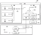
FIG. 1A shows a schematic diagram of an exemplary system 100 for 3D display. System 100 includes a computing device 102 and a holographic display device (or maxwell holographic display device) 110. Computing device 102 is configured to prepare data for a list of primitives corresponding to an object, e.g., a 3D object, and send the data to holographic display device 110 via a wired or wireless connection (e.g., a USB-C connection or any other high-speed serial connection). The holographic display device 110 is configured to calculate an electromagnetic field contribution of the list of elements to a display element (e.g. modulator) of a display screen in the holographic display device 110, modulate the display element with a pattern, e.g. a hologram, based on the calculated electromagnetic field contribution to the display screen, and display a light field corresponding to the object in 3D under illumination, e.g. holographic reconstruction. Here, the hologram refers to a pattern displayed on a display screen, which contains amplitude information or phase information about an object or a combination thereof. Holographic reconstruction refers to the volumetric light field (e.g., holographic light field) from the display screen when the holographic screen is illuminated.
Computing device 102 may be any suitable type of device, such as a desktop computer, a personal computer, a notebook, a tablet computing device, a Personal Digital Assistant (PDA), a network device, a smart mobile phone, a smart watch, an Enhanced General Packet Radio Service (EGPRS) mobile phone, a media player, a navigation device, an email device, a game console, or any suitable combination of any two or more of these or other computing devices.
Computing device 102 includes Operating System (OS)104,
operating system 104 may include
multiple applications 106 as graphics engines. The
application 106 may use standard 3D content creation tools (e.g.,
or Unity3D) to process or render a scene, e.g., any arbitrary CG model. The scene may correspond to a 3D object. The
applications 106 may operate in parallel to render a scene to obtain an
OS graphics abstraction 101, which
OS graphics abstraction 101 may be provided to a Graphics Processing Unit (GPU)108 for further processing. In some implementations, the
OS graphics abstraction 101 is provided to the
holographic display device 110 for further processing.
The GPU 108 may include specialized electronic circuitry designed for rapid manipulation of computer graphics and image processing. The GPU 108 may process the OS graphics abstraction 101 of the scene to obtain processed scene data 103 that may be used to obtain a list of primitives 105 indexed in a particular order. The primitives may include at least one of point primitives, line primitives, or polygon primitives. In some implementations, the GPU 108 includes a video driver configured to generate the processed scene data 103 and the primitive list 105.
In some implementations, the GPU 108 includes a conventional renderer 120 that can render the primitive list 105 into a list of items for drawing on a conventional monitor 124, such as a 2D display screen, through conventional rendering techniques such as culling and clipping. The list of items may be sent to a conventional monitor 124 via a screen buffer 122.
In some embodiments, the GPU 108 includes a holographic renderer 130 for rendering the list of primitives 105 into graphics data to be displayed by the holographic display device 110. The graphics data may include a list of primitives and corresponding primitive data. For example, the graphics data may include hexadecimal codes for each primitive.
In some implementations, the GPU 108 includes both a conventional renderer 120 and a holographic renderer 130. In some implementations, the GPU 108 includes a conventional renderer 120 and the holographic display device 110 includes a holographic renderer 130.
The respective primitive data for the primitives may also include color information (e.g., textured color, gradient color, or both), texture information, and/or shading information. Shading information can be obtained by any conventional CGI surface shading method that involves modulating the color or brightness of the primitive surface.
The primitive data of the primitives may include coordinate information of the primitives in a 3D coordinate system such as cartesian coordinate system XYZ, polar coordinate system, cylindrical coordinate system, and spherical coordinate system. As described in further detail below, the display elements in the holographic display device 110 may also have corresponding coordinate information in a 3D coordinate system. The primitives at coordinate locations may represent 3D objects adjacent to (e.g., in front of) the display element.
By way of example, a primitive is a colored line, e.g., a straight line that smoothly changes from one color to another over its span. The primitive requires four data elements to render: two endpoints and color information (e.g., RGB color values) at each endpoint. Assuming the hexadecimal code of the line is a0, in the 3D coordinate system, the line extends from a first endpoint (0.1,0.1,0.1) to a second endpoint (0.2,0.2,0.2), the color at the first endpoint being 1/2 blue: RGB (0, 128), and the color at the second endpoint is full red: RGB (255,0, 0). The holographic renderer determines how much data and what type of data each primitive expects. For the line, the primitive data in the primitive stream for the shading line may be the following instruction sets:
0xA0//hex code for the shaded line
0x3dcccccd//first vertex at(0.1,0.1,0.1)float(single)
0x3dcccccd
0x3dcccccd
0x000080//first vertex color is(0,0,128)
0x3e4ccccd//second vertex at(0.2,0.2,0.2)float(single)
0x3e4ccccd
0x3e4ccccd
0xff0000//second vertex color is(255,0,0)
there are a total of 31 hexadecimal words in the primitive data of the shading line primitive. This would therefore be an extremely efficient way of transmitting complex scenes, and the primitive data could be further compressed. Because each primitive is a deterministic turing step, no terminator is needed. The difference from the conventional model in which line primitives are simply drawn on a 2D display screen is that the primitive data of a line is sent to the holographic display device 110, and the holographic display device 110 can calculate a hologram and display a corresponding holographic reconstruction that presents the line floating in space.
In some implementations, computing device 102 sends non-primitive-based data, such as recorded light-field video, to holographic display device 110. Holographic display device 110 may compute sequential (sequential) holograms to display video as a sequential holographic reconstruction in space. In some implementations, computing device 102 transmits CG holographic content to holographic display device 110 simultaneously with live holographic content. Holographic display device 110 may also compute a corresponding hologram to display the content as a corresponding holographic reconstruction.
As shown in FIG. 1A, holographic display device 110 includes a controller 112 and a display screen 114. The controller 112 may include a plurality of computing units or processing units. In some embodiments, the controller 112 comprises an ASIC, a Field Programmable Gate Array (FPGA), or a GPU, or any combination thereof. In some embodiments, the controller 112 includes a holographic renderer 130 for rendering the primitive list 105 as graphics data to be computed by the computing unit. In some implementations, the controller 112 receives the OS graphics abstraction 101 from the computing device 102 for further processing. The display screen 114 may include a plurality of display elements. In some embodiments, the display screen 114 includes a Spatial Light Modulator (SLM). The SLM may be a phase SLM, an amplitude SLM, or a phase and amplitude SLM. In some examples, display screen 114 is a Digital Micromirror Device (DMD) or a Liquid Crystal On Silicon (LCOS) device. In some implementations, holographic display device 110 includes an illuminator 116 adjacent to display screen 114 and configured to emit light toward display screen 114. The illuminator 116 may be a coherent light source, such as a laser, a semi-coherent light source, such as an LED (light emitting diode), or an incoherent light source.
The difference with conventional 3D graphics systems that take a 3D scene and project it onto a 2D display device is that the holographic display device 110 is configured to produce a 3D output, such as a holographic reconstruction 117 in the form of a light field, e.g. a colored 3D volume. In a hologram, each display element contributes to each part of the scene. That is, for holographic display device 110, each display element needs to be modulated for each portion of the scene (e.g., each primitive in the list of primitives generated by GPU 108) for full rendering of the scene. In some embodiments, modulation of certain display elements may be omitted based on, for example, an acceptable level of precision in the rendered scene.
In some implementations, the controller 112 is configured to calculate the electromagnetic field contribution (e.g., phase, amplitude, or both) of each cell to each display element, and generate, for each display element, a sum of the electromagnetic field contributions of the cell list to that display element. This can be done by traversing each primitive for a given display element and accumulating (accu) its contribution to the given display element, or by traversing each display element for each primitive.
The controller 112 may calculate the electromagnetic field contribution of each cell to each display element based on a predetermined expression of the cell. Different primitives may have corresponding expressions. In some cases, the predetermined expression is an analytical expression, as further detailed below with respect to fig. 3A-3C. In some cases, the predetermined expression is determined by solving maxwell's equations using the boundary conditions defined at the display screen 114. The boundary condition may comprise a dirichlet boundary condition or a cauchy boundary condition. The display element may then be modulated based on the electromagnetic field contribution sum, for example, by modulating at least one of a refractive index, an amplitude index, a birefringence, or a retardation of the display element.
If the value of the electromagnetic field (e.g., the solution of Maxwell's equations) at each point on the surface bounding the field is known, then an accurate, unique configuration of the electromagnetic field within the volume bounded by the bounding surface can be determined. The list of elements (or the holographic reconstruction of the corresponding hologram) and the display screen 114 define a 3D space, and the surface of the display screen 114 forms part of a boundary surface of the 3D space. By setting the state of the electromagnetic field (e.g., phase or phase and amplitude states) on the surface of the display screen 114, for example by illuminating light on the display screen surface, the boundary condition of the electromagnetic field can be determined. Due to the time symmetry of maxwell's equations, a volumetric light field corresponding to a hologram can be obtained as a holographic reconstruction when the display element is modulated based on the electromagnetic field contributions from the elements corresponding to the hologram.
For example, a line cell illuminated with a specific color may be provided in front of the display screen 114. As described in further detail below with respect to fig. 3B, the analytic expression of the linear aperture may be written as a function in space. The electromagnetic field contribution from the line elements on the boundary surface comprising the display screen 114 may then be determined. If the electromagnetic field value corresponding to the calculated electromagnetic field contribution is set on the display screen 114, the same linear aperture used in the calculation may appear at the corresponding position, e.g. the coordinate position of the line element in the 3D coordinate system, due to the time symmetry of maxwell's equations.
In some examples, as detailed further below with respect to fig. 3B, assume that there is a line of light between two points a and B in 3D space. The light is emitted uniformly and the light intensity per line length l is I. At each differential dl along the line from a to B, a quantity of light proportional to I × dl is emitted. The infinity dl can act as a delta (point) source and the electromagnetic field contribution of the derivative dl to any point on the boundary surface around the scene corresponding to the primitive list can be determined. Thus, for any display element on the display screen 114, an analytical equation can be determined that represents the electromagnetic field contribution of the differential segment of the line to the display element. A particular type of summation/integration of the electromagnetic field contributions of the entire line to the electromagnetic field at the display element on the display screen may be determined as an expression, traveling along the line and accumulating the entire line. The value corresponding to the expression at the display element may be set, for example, by modulating the display element and illuminating the display element. Then, by time reversal and correction constants, the line can be created at the same position defined by the point a and the point B in the 3D space.
In some implementations, the controller 112 is coupled to the display screen 114 through a memory buffer. The control signals 112 may generate respective control signals based on a sum of the electromagnetic field contributions to each display element. The control signal is used to modulate the display element based on the sum of the electromagnetic field contributions. The respective control signals are sent to the respective display elements via the memory buffer.
In some embodiments, the controller 112 is integrated with the display screen 114 and is locally coupled to the display screen 114. As further detailed with respect to fig. 1B, the controller 112 may include several computing units each coupled to one or more respective display elements and configured to send respective control signals to each of the one or more respective display elements. Each computation unit may be configured to compute one or more primitives of a list of primitives. The computing units may operate in parallel.
In some embodiments, the illuminator 116 is coupled to the controller 112 and is configured to turn on/off based on control signals from the controller 112. For example, controller 112 may activate illuminator 116 to turn on in response to controller 112 completing the calculation (e.g., obtaining all sums of electromagnetic field contributions to the display element). As described above, when the illuminator 116 emits light onto the display screen 114, the modulated display elements cause the light to propagate in different directions to form a volumetric light field corresponding to a list of primitives, wherein the list of primitives corresponds to a 3D object. The resulting volumetric light field corresponds to a solution of maxwell's equations with boundary conditions defined by the modulated display elements of the display screen 114.
In some implementations, the controller 112 is coupled to the luminaire 116 through a memory buffer. The memory buffer may be configured to control the amplitude or brightness of light-emitting elements in the luminaire. The memory buffer for the illuminator 116 may be smaller in size than the memory buffer for the display screen 114. The number of light-emitting elements in the illuminator 116 may be smaller than the number of display elements of the display screen 114 as long as light from the light-emitting elements can be irradiated on the entire surface of the display screen 114. For example, an illuminator having 64x64 OLEDs (organic light emitting diodes) may be used for a display screen having 1024x1024 elements. Controller 112 may be configured to simultaneously activate multiple light-emitting elements of luminaire 116.
In some embodiments, the illuminator 116 is a monochromatic light source configured to emit monochromatic light, such as red, green, or blue light. In some implementations, the illuminator 116 includes two or more light-emitting elements, each configured to emit light having a different color. For example, the illuminator 116 may include red, green, and blue light emitting elements. To display a full-color 3D object, three separate red, green and blue holograms may be calculated. That is, three electromagnetic field contributions of the respective cell to the display element may be obtained. The display elements may be sequentially modulated based on the three electromagnetic field contributions, and the illuminator 116 may be controlled to sequentially turn on the red, green, and blue light emitting elements. Depending on the temporal coherence of the visual effect in the eye of the viewer, the three colors can combine in the eye to render full color. In some cases, illuminator 116 is turned off during a change of state of the displayed image (or holographic reconstruction) and turned on when the active image (or holographic reconstruction) is presented for a period of time. This may also rely on temporal coherence of vision to make the image (or holographic reconstruction) appear stable.
In some embodiments, the display screen 114 has a resolution small enough to diffract visible light, for example, a resolution on the order of 0.5 μm or less. The illuminator 116 may comprise a single source of white light, and the emitted white light may be diffracted by the display screen 114 into different colors for holographic reconstruction.
As described in further detail below with respect to fig. 5A-5F, there may be different configurations for system 100. The display screen 114 may be reflective or transmissive. The display screen 114 may have various sizes ranging from a small scale (e.g., 1-10cm on a side) to a large scale (e.g., 100 and 1000cm on a side). Illumination from illuminator 116 may come from a front surface of display screen 114 (e.g., for a reflective display screen) or from a back surface of display screen 114 (e.g., for a transmissive display screen). A planar waveguide may be used to homogenize the illumination of the surface of the display screen 114. In some embodiments, the controller 112, the illuminator 116, and the display screen 114 may be integrated together into a single unit. The integrated single unit may include, for example, a holographic renderer 130 in the controller 112.
FIG. 1B shows a schematic diagram of an exemplary holographic display device 150. Holographic display device 150 may be similar to holographic display device 110 of FIG. 1A. Holographic display device 150 includes a computing architecture 152 and a display screen 156. The computing architecture 152 may be similar to the controller 112 of FIG. 1A. The computing architecture 152 may include an array of parallel computing cores 154. The compute core may be connected to an adjacent compute core via a communication connection 159 (e.g., a USB-C connection or any other high-speed serial connection). The communication connection 159 may be included in a data distribution network through which the scene data 151 (e.g., scene primitives) may be distributed among the computing cores 154.
The display screen 156 may be similar to the display screen 114 of FIG. 1A, and may include an array of display elements 160 located on a backplane 158. The display elements 160 may be disposed on a front surface of the backplate 158, and the computing cores 154 may be disposed on a rear surface of the backplate 158. The backing plate 158 may be a substrate, such as a wafer. The computing core 154 may be on the same substrate as the display screen 156 or attached to the back surface of the display screen 156.
Each compute core 154 may be connected to a corresponding tile (or array) of display elements 160. Each computation core 154 is configured to compute respective ones of a plurality of primitives in scene data 151 in parallel with one another. In some examples, the computation core 154 is configured to compute an electromagnetic field contribution of each respective cell to each display element in the array of display elements 160, and to generate a sum of the electromagnetic field contributions of the plurality of cells to each display element in the respective section of the display elements 160. The computing core 154 may receive the electromagnetic field contributions of other ones of the computed plurality of elements to each of the respective tiles of the display elements 160 from other computing cores of the array of the computing core 154 and generate an electromagnetic field contribution sum based on the received computed electromagnetic field contributions. The computing core 154 may generate a control signal for each display element in the respective section of display elements to modulate at least one characteristic of each display element in the respective section of display elements 160 based on a sum of electromagnetic field contributions to the display elements.
As described above, the computing architecture 152 may also generate control signals to the illuminator 162, for example, in response to determining that the calculation of the sum of the electromagnetic field contributions to each display element for the plurality of primitives has been completed. Illuminator 162 emits input light 153 to illuminate modulated display elements 160, and input light 153 is reflected by modulated display elements 160 to form a volumetric light field, e.g., holographic light field 155, corresponding to scene data 151.
As shown in fig. 1B, the sections of display elements 160 may be interconnected into a larger display screen. Accordingly, the compute cores 154 may be interconnected for data communications and distribution. Note that the parameter that varies in the holographic calculations between any given two display elements is their physical location. Thus, the task of computing holograms may be shared equally among the respective computing cores 154, and the entire display 150 may operate at the same speed as a single tile, i.e., regardless of the number of tiles.
FIG. 1C illustrates an exemplary system 170 for displaying objects in 3D space. System 170 may include a computing device, such as computing device 102 of FIG. 1A, and a holographic display device 172, such as holographic display 110 of FIG. 1A or holographic display 150 of FIG. 1B. A user may operate the system 170 using input devices, such as a keyboard 174 and/or a mouse 176. For example, a user may create CG models for 2D object 178 and 3D object 180 through a computing device. Computing device or holographic display device 172 may include a holographic renderer, such as holographic renderer 130 of fig. 1A, to render a CG model to generate respective graphics data for 2D object 178 and 3D object 180. The graphics data may include corresponding primitive data for a list of primitives corresponding to objects 178 and 180.
The holographic display device 172 may include a controller, such as the controller 112 of FIG. 1A or the controller 152 of FIG. 1B, and a display screen 173, such as the display screen 114 of FIG. 1A or the display screen 156 of FIG. 1B. The controller may calculate a respective electromagnetic field contribution sum of the cell to each display element of the display screen 173 and generate a control signal for modulating each display element based on the respective electromagnetic field contribution sum. The holographic display device 172 may also include an illuminator, such as the illuminator 116 of FIG. 1A or the illuminator 162 of FIG. 1B. The controller may generate timing control signals to activate the luminaires. When light from the illuminator impinges on the surface of display screen 173, the modulated display elements may cause the light to propagate in 3D space to form a volumetric light field corresponding to the holographic reconstruction for 2D object 178 and the holographic reconstruction for 3D object 180. Thus, 2D object 178 and 3D object 180 are displayed as respective holographic reconstructions floating in 3D space in front of display screen 173.
In some implementations, the computing device sends non-primitive-based data (e.g., recorded light field video) to the holographic display device 172. The holographic display device 172 may calculate and generate a respective hologram (e.g., a series of sequential holograms) to display as a respective holographic reconstruction in 3D space. In some implementations, the computing device transmits CG holographic content to the holographic display device 172 simultaneously with live holographic content. The holographic display device 172 may also calculate and generate respective holograms to display the content as respective holographic reconstructions in 3D space.
Fig. 2 shows an exemplary configuration 200 for Electromagnetic (EM) field computation. The 3D space 208 has therein a display screen 202 (e.g., an LCOS device) including an array of display elements 204 and a cell list including dot cells 206. The 3D space 208 includes a boundary surface 210. In the 3D coordinate system XYZ, the point cell 206 has coordinate information (x, y, z). Each display element 204 is located in a plane with respect to the other display elements 204 and has a 2D position (u, v). The display element 204 also has a position in 3D space. Through mathematical point transformation, the 2D position (u, v) may be transformed into six coordinates 250 in a 3D coordinate system. That is, the surface of the display screen 202 forms a portion of the boundary surface 210. Thus, the electromagnetic field contribution of the list of elements to the display element, calculated by defining the boundary conditions at the surface of the display screen 202, represents a portion of the total electromagnetic field contribution of the elements to the display element. A scaling factor (e.g., six) may be multiplied by the sum of the electromagnetic field contributions to each display element to obtain a scaled sum of the electromagnetic field contributions, and the display elements may be modulated based on the scaled sum of the electromagnetic field contributions.
Exemplary electromagnetic field contribution of a cell
Primitives may be used for standard computer graphics rendering. Each type of element in a standard computer graphic corresponds in this process to a discrete mathematical function defining a single holographic element added to the graphic element of the hologram. Each type of primitive may correspond to an expression for calculating the electromagnetic field contribution to the display element. The primitives may be point primitives, line primitives, or polygon (e.g., triangle) primitives. As shown below, the analytic expression may be derived by calculating the electromagnetic field propagation from the corresponding element to the display element of the display screen.
FIG. 3A illustrates an exemplary electromagnetic propagation from a dot primitive 304 to a display element 302 of a display screen 300. In the 3D coordinate system XYZ, the z-coordinate is assumed to be 0 on the display screen 300, which means that the z-value is negative behind the display screen 300 and positive in front of the display screen 300. The coordinates of the point primitive 304 are (x, y, z), and the coordinates of the display element 302 are (u, v, 0). Distance d between point primitive 304 and display element 302 uv May be determined based on their coordinates.
The dot primitive 304 may be considered a dot charge with a time-varying amplitude. According to electromagnetic theory, the electric field E generated by such point charges can be expressed as:
where λ represents the wavelength of the electromagnetic wave and d represents the distance from the point charge.
Thus, the electric field E at the display element (u, v) u,v Can be expressed as:
where I represents the relative strength of the hogel electric field contributed by the point element 304 at the display element.
As described above with respect to fig. 1, the surface of the
display screen 300 forms only a portion of the boundary surface of the electromagnetic field. The scale factor delta may be applied to the electric field E
u,v To obtain a scaled electric field at the display element adjusted for the partial boundary
Fig. 3B shows an example of electromagnetic propagation from the line cell 306 to the display element 302 of the display screen 300 in the 3D coordinate system XYZ. As described above, the coordinates of the display element 302 may be (u, v,0), where z is 0. Two endpoints P of the line primitive 306 0 And P 1 Are (x0, y0, z0) and (x1, y1, z1), respectively. Endpoint P 0 Distance d from display element 0 May be determined based on their coordinates. Similarly, endpoint P 1 Distance d from display element 1 May be determined based on their coordinates. Two end points P 0 And P 1 A distance d therebetween 01 Can also be determined, e.g. d 01 =d 1 -d 0 。
As described above, the line primitives may be considered as superpositions or linear deformations, and the corresponding analytic expressions of the line primitives as linear apertures may be obtained as distributed incremental functions in space. The analytical expression may be a closed expression that is a continuous 3D line segment of the hologram.
Fig. 3C shows an exemplary electromagnetic propagation from a triangle cell 308 to a display element 302 of the display screen 300 in a 3D coordinate system XYZ. As described above, the coordinates of the display element 302 may be (u, v,0), where z is 0. Triangle primitive 308 has three endpoints: p 0 (x 0 ,y 0 ,z 0 )、P 1 (x 1 ,y 1 ,z 1 ) And P 2 (x 2 ,y 2 ,z 2 ). Display elements and endpoints P 0 、P 1 And P 2 A distance d between 0 、d 1 And d 2 May be determined based on their coordinates, respectively.
Similar to the line elements in fig. 3B, the triangle elements may be considered as continuous apertures in space, and an analytic expression of the electromagnetic field contribution of the triangle elements to the display element may be obtained by integration. This can be simplified to obtain an expression for efficient computation.
Exemplary computation of primitives
As described above, a controller, such as controller 112 of FIG. 1, may calculate the electromagnetic field contribution of the cell to the display element based on an analytic expression that may be determined as shown above. The electromagnetic field contribution of the line element is calculated, for example, as follows.
Each display element in the display screen has a physical location in space, and each display element lies in a plane relative to the other display elements. Assuming that the display elements and their controllers are arranged as is customary in display and storage devices, a simple mathematical point transformation can be used to transform the logical position of a given display element to the actual physical position of the display element in space based on the logical storage address of the display element in the processor. Thus, as the logical memory address of the display element cycles through the logical memory space of the processor, the corresponding actual physical location in the surface space of the display screen may be identified.
As an example, if the pitch (pitch) of the display screen is 5 μm, each logical address increment may be moved 5 μm in the x-direction, and when the x-resolution limit of the display screen is reached, the next increment will be moved back to the original x-physical location and increase the y-physical location by 5 μm. It may be assumed that the third spatial coordinate z is zero on the display screen surface, which means that negative z-values are behind the display screen and positive z-values are in front of the display screen.
To begin line computation, a scaled physical distance between the current display element and each of two points of the line primitive may be determined as d 0 And d 1 . In fact, d 0 And d 1 One can calculate once per primitive because each subsequent calculation of distance for all display elements is a small change in initial value. In this way, the calculation is performed in one dimension.
An exemplary computational process for each primitive may include the following computational code:
DD=f(d 1 ,d 0 ),
iscale=SS*COLOR*Alpha1,
C1=-2*iscale*sin(DD/2)*sin((Alpha2)*cos(Alpha3),
C2=-2*iscale*sin(DD/2)*sin(Alpha2)*sin(Alpha4),
where SS, Alpha1, Alpha2, Alpha3, and Alpha4 are pre-computed constants, COLOR is the RGB COLOR values passed with the primitive, and all values are scalar, single precision floating point numbers. Both the sine and cosine functions may be looked up in a table stored in the controller to improve computational efficiency.
The results of C1 and C2 are then accumulated for each primitive at each display element, e.g., in an accumulator for the display element, and may be normalized once at the end of the calculation for the display element. At this time, as described above, the controller may send a first control signal to the display element to modulate the display element based on the calculated result, and send a second control signal to the illuminator to turn on the illuminator to emit light. Thus, the holographic reconstruction (or holographic light field) is visible to a viewer. When the modulated display elements are illuminated, the light is caused to produce clear, continuous color lines in three-dimensional space.
In some embodiments, calculating the code includes clearing a previously accumulated hexadecimal code in the accumulator, for example, at the beginning of the code. The calculation code may also include, for example at the end of the code, a hexadecimal code for storing the accumulator results into a respective memory buffer for each display element. In some implementations, a computing device, such as computing device 102 of fig. 1A, sends a plurality of background or static primitive hexadecimals to a controller at application startup or at intervals between displaying frames that do not affect the primary display frame rate. The computing device may then send one or more combinations of hexadecimal codes, potentially along with other foreground or dynamic primitives, at a higher rate to a controller, which may form corresponding control signals to modulate the display elements of the display screen.
The computational process can be several orders of magnitude simpler and faster than the most efficient line drawing routines in conventional 2D display technologies. Furthermore, the calculation algorithm scales linearly with the number of display elements. Thus, scaling the computing unit of the controller to a 2D networked processing system can keep up with the increased computing needs of the surface area of the display screen.
Exemplary computing embodiments
For example, maxwell holographic controller of controller 112 of fig. 1A may calculate the electromagnetic field contribution of the elements to the display element based on an analytic expression that may be determined as shown above. The controller may be implemented in, for example, an ASIC, FPGA, or GPU, or any combination thereof.
In modern GPU pipelines, GPUs perform descriptions of geometry and vertex and fragment shading programs to generate color and depth pixel outputs to one or more output image surfaces (referred to as render targets). This process involves an explosive fanout (explicit fan-out) of information, where the geometry is extended to colored segments, followed by visibility tests to select whether some work needs to be done on each of these segments. A fragment is a record that contains all the information involved in coloring the sample point (e.g., barycentric coordinates of a triangle, interpolated values (such as color or texture coordinates), surface derivatives, etc.). Creating these records and then rejecting the processing of those records that do not contribute to the final image, i.e. the visibility test. Fragments that pass the visibility test can be packaged into a workgroup called wave front (wave front) or warp (warp) that is executed in parallel by the shader engine. These produce output values that are written back to memory as pixel values, ready for display, or used as input textures for later rendering channels.
In maxwell holography, the rendering process can be significantly simplified. In maxwell holographic computing, each cell contributes to each display element. There is no need to extend the geometry to the pixels and no need to apply visibility tests before packing wave fronts (packing wave fronts). This may also remove the need for decision making or communication between maxwell holographic pipelines, and allow the computation to be a parallel problem with multiple possible solutions, each adjusted to speed, cost, size, or energy optimization. The graphics pipeline is significantly shorter, has fewer intermediate steps, no data copying or moving, and has fewer decisions, resulting in lower latency between initiating rendering and the results being ready for display. This may allow maxwell holographic rendering to create very low latency displays. As described below, this may allow maxwell holographic calculations to improve accuracy, for example, by using fixed-point numbers in a maxwell holographic pipeline, and optimize calculation speed, for example, by optimizing mathematical functions.
Using fixed point number
The intermediate calculations involve generating very large values when calculating the electromagnetic field contribution of each element at each display element (e.g., phase unit). These large values involve special handling because they also require a fractional part to be preserved during computation.
Floating point values have the following disadvantages: they are most accurate near the origin (zero on the number axis) and lose one bit of accuracy every second power when moving away from the origin. For values close to the range of [ -1,1], the precision of the floating-point value may be higher, but once tens of millions of values are reached, for example to the extent that a single precision 32-bit IEEE-754 floating-point value has no remaining decimal places, the whole significand (also known as the mantissa) is used to represent the integer part of the value. However, what maxwell holography is particularly interested in retaining is the fractional part of the large value.
In some cases, fixed-point numbers are used in maxwell holographic calculations. The fixed point number represents a numerical value in which the decimal point does not change depending on the situation. By selecting the correct number of bits for the integer and fractional parts of the value, the same number of fractional bits can be obtained regardless of the size of the value. The fixed-point number representation is an integer with an implicit scale factor, e.g., 14.375 may be represented as a numerical value 3680 (negative binary 000011100100000) in a 16-bit fixed-point value with 8 decimal bits. This can also be expressed as an "unsigned 16.8" fixed point number, or simply as u 16.8. Negative numbers may have one additional sign bit and are stored in the "2 s expression (2s complement)" format. This can greatly improve the accuracy of the calculation.
Optimization of mathematical functions
As indicated above, Maxwell's holographic calculations involve the use of a priori mathematical functions, such as sine, cosine, arctangent, etc. In the CPU, these functions are implemented as floating point library functions that may use special CPU instructions, or on the GPU as floating point units in the GPU. These functions are written with arguments as floating point numbers and return results in the same floating point representation. These functions are constructed so that for the general case they are accurate where the floating point number is accurate, rounded correctly, and handle every edge case in the floating point number representation (+/-infinity, not numeric value, signed zero, and abnormal floating point number).
In maxwell holographic computing, with fixed point representation, there is no need to use anomalous floating point numbers for progressive underflow, there is no need to handle non-numeric values from operations like divide by 0, there is no need to alter the floating point rounding mode, and there is no need to cause floating point exceptions to the operating system. All this allows to simplify (and/or optimize) the a priori mathematical function, for example as described below.
In some cases, an optimization may be performed to take the argument in one fixed point format and return the value to a different level of precision, e.g., input 28.12 and output 15.14. This may be particularly desirable when calculating sinusoids of large values, in the tens of millions, the input arguments may be large, but the output may only need to represent a range of values [ -1,1], or arctangent taking any value but returning values in the range [ -pi/2, pi/2 ].
In some cases, depending on the input range involved, optimization may be done to freely implement the prior function as a fully enumerated look-up table, interpolation table, or as a half-table based polynomial function or a half-table based fully infinitesimal maximum polynomial. This optimization also allows for the application of a specific range reduction method for processing larger inputs, which general purpose GPU pipeline computations may skip due to speed.
In some cases, another optimization may be to transform the trigonometric computation from the range [ - π, π ] to a signed 2's representation in the range [ -1,1], which has the advantage of not requiring costly division by 2 π modulo arithmetic.
Exemplary embodiments of the occlusion
Occlusion is often seen as a significant problem in computer graphics, and even more so in computer holography. This is because, in at least some cases, while the occlusion problem in the projected CGI is static, what is hidden and what is visible in the holographic system depends on the position and orientation of the viewer. Wave methods of G-S holography or its derivatives have been developed to address holographic obscuration. However, in the G-S approach, masking or blocking contributions from portions located behind other portions in the scene can be very complex and computationally expensive.
In maxwell holography, the occlusion problem can be solved relatively easily, since which display elements (e.g., phase cells) correspond to which elements are fully deterministic and subtle. For example, when performing calculations for a given primitive, it may be determined whether a given display element contributes to the reconstruction of the given primitive. After determining that several display elements do not contribute to a given element due to occlusion, in calculating the sum of electromagnetic field contributions to one of the several display elements, the electromagnetic field contribution from the given element is omitted from the calculation of the sum of electromagnetic field contributions to one of the several display elements.
For illustration only, fig. 3D to 3F show display elements that do not contribute to a given primitive (a point in fig. 3D, a line in fig. 3E, and a triangle in fig. 3F) in the case where a line primitive is determined as an occlusion. The starting point of the line primitive is O1 and the ending point is O2.
As shown in FIG. 3D, point primitive P0 is behind the barrier and closer to the display screen. By extending the line connecting O1-P0 and O2-P0, the range D1 to D2 of display elements in the display screen that do not contribute to the reconstruction of the point cell P0 is determined.
In some examples, the coordinate information of O1, O2, and P0 is known, e.g., stored in a "Z" buffer calculated by a GPU (e.g., GPU 108 of fig. 1A) prior to sending the scene to a maxwell holographic controller (e.g., controller 112 of fig. 1A). For example, in the XZ plane where y is 0, the coordinate information may be O1(Ox1, Oz1), O2(Ox2, Oz2), and PO (Px, Pz), where Oz1 is Oz2 ═ Oz. Based on the coordinate information, the coordinate information of D1 and D2 may be determined as:
Dx1=Px+ρ(Px-Ox2),Dx2=Dx1+ρ(Ox2-Ox1) (4),
where ρ ═ Pz/(Oz-Pz), and Dz1 ═ Dz2 ═ 0.
In addition to the information in the Z buffer for the dot cell P0, the information of D1 and D2 may be stored as additional information in the "S" buffer for the Maxwell holographic controller. In this way, the additional information may be used to simply mask the contribution of a particular display element (ranging from D1 to D2) to a particular primitive P0 in the indexed list of primitives.
FIG. 3E illustrates a determination of how a particular display element contributes to a line primitive in the case of an obstruction in front of the line primitive. By connecting the specific display element D0 to the start point O1 and the end point O2 of the shade, two point cells P1 and P2 on the line cell are determined as the intersection point. Therefore, the specific display element D0 does not contribute to the reconstruction of the line cell portion from P1 to P2 on the line cell. Thus, when calculating the sum of the electromagnetic field contributions to a particular display element D0, the electromagnetic field contributions from the P1-P2 portions of the line cell are not calculated.
This can be achieved in two ways. In the first way, the electromagnetic field contributions of the portion P0-P1 and the portion P2-Pn to the specific display element D0 are added as the electromagnetic field contributions of the line cells to the specific display element D0 by taking into account the occlusion from the shade. In the second way, the electromagnetic field contributions from the whole line elements P0-Pn and from the P1-P2 portion are calculated, and by taking into account the occlusion from the obstruction, the difference between the two calculated electromagnetic field contributions can be considered as the electromagnetic field contribution of the line element to the particular display element D0. The coordinate information of the P1 and P2 or P1-P2 portions may be stored in the "S" buffer of the Maxwell holographic controller as a line cell portion that does not contribute to a particular display element, D0, along with information of the occlusion and other information in the "Z" buffer of the GPU.
FIG. 3F illustrates a determination of how a particular display element contributes to a triangle primitive if the obstruction is in front of the triangle primitive. By connecting the specific display element D0 to the start point O1 and the end point O2 of the shade, four point cells P1, P2, P3, and P4 on the sides of the triangle cell are determined as intersection points. Therefore, the specific display element D0 is added to the triangle primitives by points P1, P2, P3, P4, P C The reconstruction of the enclosed portion does not contribute. Thus, when the sum of the electromagnetic field contributions to a particular display element D0 is calculated, P1-P2-P3-P4-P from the triangle cells are not calculated C Part of the electromagnetic field contribution. That is, only the free point P is selected by considering the occlusion of the occlusion object A A first triangle formed by points P1 and P2 and a second triangle formed by points P B The electromagnetic field contributions of the second triangle formed by P3 and P4 add up as a triangle element P A -P B -P C Is detected. P1, P2, P3 and P4 or triangle primitives P A -P1-P2 and P B Coordinate information of-P3-P4 may be as triangle primitives P A -P B -P C Is stored in the "S" buffer of the maxwell holographic controller, along with information of the obstruction and other information in the "Z" buffer of the GPU.
Implementation of occlusion in maxwell holography enables conversion of a "Z" buffer in a GPU to an "S" buffer in a maxwell holographic controller, and can mask the contribution of a particular primitive (or a particular portion of a primitive) in an indexed list of primitives to a particular display element. This not only provides accurate, physically correct occlusion, but also saves computation time, as primitives that do not contribute to a given display element continue to be used for computation for the next display element. The "S" buffer may contain additional information related to the diffraction efficiency of the display screen.
The "S" buffer may also include rendering features, such as holographic specular highlights, where the reflectivity of the surface depends on the viewing angle. In conventional CGI, specular highlights depend only on the orientation of the rendered object, while in maxwell holographic background, the direction from which the object is viewed also plays a role. Thus, the geometric mirror information can be encoded in the "S" buffer as an additive (mirror) rather than a subtractive (occlusion) contribution. In Maxwell holography, the mathematical operation of holographic specular highlights can be substantially the same as the mathematical operation of holographic obscuration.
Exemplary embodiments of the bonding
When light is illuminated on a display screen that is modulated with electromagnetic field contributions from a list of elements of a 3D object, the modulated display screen causes the light to propagate in different directions to form a volumetric light field corresponding to the elements. The volumetric light field is a maxwell holographic reconstruction. Two adjacent primitives (e.g., triangle primitives) in the 3D object have a shared edge. During reconstruction, stitching problems may arise, wherein the light intensity of the shared edge may be doubled due to the separate reconstruction of two adjacent primitives. This may affect the appearance of the reconstructed 3D object.
To solve the problem of the junction in maxwell holography, as shown in fig. 3G, adjacent cells may be reduced by a predetermined factor so that a gap may be formed between the adjacent cells. In some cases, rather than scaling down two adjacent primitives, only one primitive or a portion of a primitive is scaled down. For example, a line in a triangle primitive may be shrunk to be separated from another triangle primitive. In some cases, scaling may include scaling different portions of the primitive with different predetermined factors. The scaling may be designed such that the gap is large enough to minimize the stitching problem of neighboring primitives and small enough for the reconstructed 3D object to appear seamlessly. The predetermined factor may be determined based on information of the display screen (e.g., a maximum spatial resolution of the display screen).
In some cases, the scaling operation may be applied to primitive data of primitives obtained from a holographic renderer (e.g., holographic renderer 130 of fig. 1A) and the scaled primitive data of the primitives is sent to a maxwell holographic controller, e.g., controller 112 of fig. 1A. In some cases, the controller may perform a scaling operation on the primitive data obtained from the holographic renderer before calculating the electromagnetic field contribution of the primitive to the display elements of the display screen.
Exemplary embodiments of texture mapping
Texture mapping is a technique developed in computer graphics. The basic concept is as follows: taking a source image and applying it as a decal to a surface in a CGI system enables rendering details into a scene without adding complex geometry. Texture mapping may include techniques for creating realistic illumination and surface effects in CGI systems, and may broadly refer to the application of surface data to triangular meshes.
In maxwell holography, an analytic relationship between arbitrary triangles in space and the phase pattern on the holographic device can be used to render a plane-rendered and interpolated triangular mesh in real 3D. However, for compatibility with modern rendering engines, the ability to map information on the surfaces of these triangles is involved. This may present a practical problem because the speed of the method stems from the presence of analytical mappings, which do not tolerate data-driven amplitude variations.
The Discrete Cosine Transform (DCT) is an image compression technique and can be considered as a real valued version of the FFT (fast fourier transform). DCT depends on the encoding-decoding process that assigns weights to cosine harmonics in a given image. The result of the encoding is a set of weights, where the number of weights is equal to the number of pixels in the original image, and if each weight is used to reconstruct the image, no information will be lost. However, in many images, acceptable reconstruction can be done from a small subset of weights, thereby achieving large compression rates.
The decoding (rendering) process of the DCT in two dimensions involves a weighted floating point sum (double sum) of each DCT weight and each target pixel. This can be applied to Maxwell holography for texture mapping. In maxwell holography, triangle rendering involves a "spike" double integration in phase space to determine the phase contribution of any individual phase to the triangle in question. The integrals can be folded into floating point type summations, which reflect the integrals in the DCT reconstruction, followed by re-deriving the analytic triangle expression according to the DCT weights. This implementation of the DCT technique in maxwell holographic computing enables the rendering of complete texture mapped triangles, employing image compression on the data of the rendered texture triangles, and taking advantage of the existing toolset that uses DCT/JPEG to automatically compress texture and image data.
In some embodiments, to draw maxwell holographic textured triangles, the spatial resolution required for the mapping on the specified surface is first calculated. Then, the texture with this resolution is provided and the DCT compressed with the angle and origin information is obtained to correctly locate it on the triangle. Then, the list of corners and DCT weights of the triangle is included in the index primitive list and sent to the maxwell holographic controller. The DCT weights may be included in the electromagnetic field contribution of the triangle elements to each display element. Texture triangles may be n times slower than planar triangles, where n is the number of (non-zero) DCT weights sent with the primitive. Modern techniques for "fragment shading" can be implemented in maxwell holographic systems, where the step of DCT encoding replaces the filtering step used for conventional projection rendering.
As an example, the following expression shows the DCT weight B of an image pq :
Wherein,
m and N are the corners of the rectangular image, and (p, q) are the DCT terms.
By decoding, the amplitude value Amn can be obtained as follows:
When calculating the electromagnetic field contribution of a textured triangle primitive to a display element (e.g., a phase cell), have corresponding DCT weights
The DCT term of (a) may be included in the following calculation:
wherein X, Y is the corner of a triangle in the coordinate system, T corresponds to the electromagnetic field contribution of the triangle element to the display element, and
for non-zero terms B in DCT
pq Is added to the system. The number of (p, q) DCT terms may be selected by considering both information loss and information compression in reconstruction.
Exemplary processing
Fig. 4 is a flow diagram of an exemplary process 400 for 3D display of objects. Process 400 may be performed by a controller for a display screen. The controller may be the controller 112 of FIG. 1A or the controller 152 of FIG. 1B. The display screen may be the display screen 114 of FIG. 1A or the display screen 156 of FIG. 1B.
Data including primitive data for each of a plurality of primitives corresponding to an object in a 3D space is obtained (402). The data may be obtained from a computing device, such as computing device 102 of FIG. 1A. The computing device may process the scene to generate primitives corresponding to the objects. The computing device may include a renderer to generate primitive data for the primitives. In some embodiments, the controller itself generates the data, for example by rendering a scene.
The primitives may include at least one of point primitives, line primitives, or polygon primitives. The primitive list is indexed in a particular order, e.g., by which the object can be reconstructed. The primitive data may include color information having textured colors and/or gradient colors. For example, the line primitives may have gradient colors and/or textured colors. The polygon primitives may also have gradient colors and/or textured colors. The primitive data may also include texture information for the primitive and/or shading information on one or more surfaces (e.g., triangles) of the primitive. The shading information may include modulation of color and/or brightness on one or more surfaces of the primitive. The primitive data may also include corresponding coordinate information of the primitives in a 3D coordinate system.
The display screen may include a plurality of display elements and the controller may include a plurality of computing units. The respective coordinate information of each display element in the 3D coordinate system may be determined based on the respective coordinate information of the primitive list in the 3D coordinate system. For example, the distance between the display screen and the object corresponding to the primitive may be predetermined. Based on the predetermined distance and the coordinate information of the primitive, coordinate information of the display element may be determined. The respective coordinate information for each display element may correspond to a logical memory address stored in memory for that display element. In this way, when the controller cycles through logical memory addresses for display elements in a logical memory space of the controller, the corresponding actual physical location of the display element in that space may be identified.
Electromagnetic field contributions (404) of a plurality of elements to each display element are determined by calculating electromagnetic field propagation from each of the plurality of elements to the display element in a 3D coordinate system. The electromagnetic field contribution may include a phase contribution and/or an amplitude contribution.
As described above with respect to fig. 3A-3C, at least one distance between a primitive and a display element may be determined based on respective coordinate information of the display element and respective coordinate information of the primitive. In some cases, the at least one distance may be calculated or calculated only once for each primitive. For example, the controller may determine a first distance between a first primitive of the primitives and a first element of the display elements based on respective coordinate information of the first primitive and respective coordinate information of the first element, and determine a second distance between the first primitive and a second element of the elements based on the first distance and a distance between the first element and the second element. The distance between the first element and the second element may be predetermined based on a pitch of a plurality of elements of the display screen.
The controller may determine an electromagnetic field contribution of the cell to the display element based on the predetermined expression of the cell and the at least one distance. In some cases, as described above with respect to fig. 3A-3C, the predetermined expression may be determined by analytically calculating electromagnetic field propagation from the cell to the display element. In some cases, the predetermined expression is determined by solving maxwell's equations. In particular, Maxwell's equations may be solved by providing boundary conditions defined at the surface of the display screen. The boundary condition may comprise a dirichlet boundary condition or a cauchy boundary condition. The primitives and display elements are in a 3D space, and the surface of the display screen forms part of a boundary surface of the 3D space. The predetermined expression may include at least one of a function including a sine function, a cosine function, and an exponential function. During the calculation, the controller may identify a value of the at least one function in a table stored in the memory, which may improve the calculation speed. The controller may determine the electromagnetic field contribution to each display element for each cell by: determining a first electromagnetic field contribution of the first element to the display element is performed in parallel with determining a second electromagnetic field contribution of the second element to the display element.
For each display element, a sum of electromagnetic field contributions of the list of elements to the display element is generated (406).
In some implementations, the controller determines and sums a first electromagnetic field contribution for the first display element by the plurality of elements and a second electromagnetic field contribution for the second display element by the plurality of elements. The controller may comprise a plurality of computing units. The controller may perform the determining of the electromagnetic field contribution of the first element to the first element by the first calculation unit in parallel with the determining of the electromagnetic field contribution of the second element to the first element by the second calculation unit.
In some implementations, the controller determines a respective first electromagnetic field contribution of the first element to each display element and determines a respective second electromagnetic field contribution of the second element to each display element. The controller then accumulates the electromagnetic field contribution to the display element by adding the respective second electromagnetic field contribution to the display element to the respective first electromagnetic field contribution. In particular, the controller may proceed in parallel with determining the respective first electromagnetic field contribution of the first element to each display element by using the first calculation unit and determining the respective second electromagnetic field contribution of the second element to each display element by using the second calculation unit.
A first control signal is sent to the display screen for modulating at least one characteristic of each display element based on a sum of the electromagnetic field contributions to the display element (408). The at least one characteristic of the display element comprises at least one of refractive index, amplitude index, birefringence or retardation.
The controller may generate, for each display element, a respective control signal based on a sum of electromagnetic field contributions of the plurality of primitives to the display element. The respective control signals are used to modulate at least one characteristic of the element based on a sum of electromagnetic field contributions of the plurality of elements to the element. That is, the first control signal comprises a respective control signal for the display element.
In some examples, the display screen is controlled by an electrical signal. The corresponding control signal may then be an electrical signal. For example, LCOS displays include an array of tiny electrodes whose voltages are individually controlled as the intensity of the elements. LCOS displays can be filled with birefringent Liquid Crystal (LC) formulations that change their refractive index. Accordingly, the respective control signals from the controller may control the relative refractive indices of the respective display elements, and accordingly the relative phase of the light passing through the display screen.
As mentioned above, the display screen surface forms part of the boundary surface. The controller may multiply the scaling factor by a sum of the electromagnetic field contributions for each display element to obtain a scaled sum of the electromagnetic field contributions, and generate a respective control signal based on the scaled sum of the electromagnetic field contributions for the display element. In some cases, the controller may normalize the sum of the electromagnetic field contributions for each of, for example, all of the display elements, and generate the respective control signal based on the normalized sum of the electromagnetic field contributions for that display element.
A second control signal is sent to the illuminator, the second control signal for turning on the illuminator to illuminate light on the modulated display screen (410). The controller may generate and send a second control signal in response to determining that a sum of electromagnetic field contributions to each display element has been obtained. Due to temporal symmetry (or conservation of energy), the modulated display elements of the display screen may cause light to propagate in different directions to form a volumetric light field corresponding to an object in 3D space. The volumetric light field may correspond to a solution of maxwell's equations with boundary conditions defined by the modulated display elements of the display screen.
In some embodiments, the luminaire is coupled to the controller through a memory buffer configured to control the amplitude or brightness of one or more light-emitting elements in the luminaire. The size of the memory buffer for the illuminator may be smaller than the memory buffer for the display screen. The number of light emitting elements in the illuminator may be less than the number of display elements of the display screen. The controller may be configured to simultaneously activate one or more light-emitting elements of the luminaire.
In some examples, the luminaire includes two or more light-emitting elements, each configured to emit light having a different color. The controller may be configured to sequentially modulate the display screen with information associated with the first color during a first time period and information associated with the second color during a sequential second time period, and control the illuminator to sequentially turn on the first light-emitting elements to emit light having the first color during the first time period and the second light-emitting elements to emit light having the second color during the second time period. In this way, a multi-colored object may be displayed in 3D space.
In some examples, the display screen has a resolution small enough to diffract light. The illuminator may emit white light onto the display screen, which may diffract the white light into light having different colors, thereby displaying a multi-colored object.
Exemplary System
Fig. 5A-5F illustrate embodiments of exemplary systems for 3D display. Any of the systems may correspond to, for example, system 100 of FIG. 1A.
Fig. 5A shows a system 500 with a reflective display screen. System 500 includes a computer 502, a controller 510 (e.g., an ASIC), a display 512 (e.g., an LCOS device), and an illuminator 514. Computer 502 may be computing device 102 of FIG. 1A and controller 510 may be controller 112 of FIG. 1A. The display 512 may be the display 114 of FIG. 1A and the illuminator 514 may be the illuminator 116 of FIG. 1A.
As shown in fig. 5A, computer 502 includes an application 504 having a renderer 503 for rendering a scene of objects. The rendered scene data is sequentially processed by the video driver 505 and the GPU 506. GPU 506 may be GPU 108 of fig. 1A and is configured to generate a primitive list and corresponding primitive data corresponding to a scene. For example, the video driver 505 may be configured to process rendered scene data and generate a list of primitives. As described above, GPU 506 can include a conventional 2D renderer, such as conventional 2D renderer 120 of FIG. 1A, to render primitives as a list of items to draw on 2D display 508. The GPU 506 or the controller 510 may include a holographic renderer, such as the holographic renderer 130 of fig. 1A, to render the list of primitives as graphics data to be displayed by the display screen 512.
The controller 510 is configured to receive the graphics data from the computer 502, calculate an electromagnetic field contribution of the list of primitives to each display element of the display screen 512, and generate a respective electromagnetic field contribution sum of the primitives to each display element. The controller 510 may generate a respective control signal for each display element to modulate at least one characteristic of the display element. The controller may send corresponding control signals to the display elements of the display screen 512 through the memory buffer 511 for the display screen 512.
The controller 510 may also generate and send control signals, such as illumination timing signals, to activate the luminaire 514. For example, in response to determining that the sum of the electromagnetic field contributions of the computational cells to the display element is complete, the controller 510 may generate and transmit a control signal. As described above, the controller 510 may send control signals to the luminaire 514 via the memory buffer. The memory buffer may be configured to control the amplitude or brightness of the light-emitting elements in the luminaire 514 and simultaneously activate the light-emitting elements.
As shown in fig. 5A, the illuminator 514 may emit a collimated beam of light 516 that is incident on the front surface of the display screen 512 at an angle of incidence in a range between 0 and 90 degrees. The emitted light beams are reflected from the front surface of the display screen 512 to form a holographic light field 518, which corresponds to an object viewable by a viewer.
Fig. 5B shows another system 520 with another reflective display screen 524. System 520 has a larger reflective display 524 compared to system 500 of fig. 5A. To accommodate this, the display controller 522 is included in a wedge-shaped housing, which may be a support for the illuminator 526. The controller 522 is similar to the controller 510 of fig. 5A and may be configured to receive graphics data from the computer 521, calculate an electromagnetic field contribution of the plurality of cells to each display element of the display screen 524, and generate a respective electromagnetic field contribution sum of the plurality of cells to each display element. The controller 522 then generates a respective control signal for each display element to modulate at least one characteristic of the display element and sends the respective control signal to the display elements of the display screen 524 through the memory buffer 523 for the display screen 524.
The controller 522 also sends a control signal to the illuminator 526 to activate the illuminator 526. The illuminator 526 emits a diverging or semi-collimated light beam 527 to cover the entire surface of the display screen 524. Light beam 527 is reflected by modulated display screen 524 to form holographic light field 528.
Fig. 5C shows a system 530 having a transmissive display screen 534. The transmissive display screen 534 may be, for example, a large display screen. The system 530 includes a controller 532, which may be similar to the controller 510 of FIG. 5A. The controller 532 may be configured to receive the graphics data from the computer 531, calculate an electromagnetic field contribution of the plurality of primitives to each display element of the display screen 534, and generate a respective electromagnetic field contribution sum of the plurality of primitives to each display element. The controller 532 then generates a respective control signal for each display element to modulate at least one characteristic of the display element and sends the respective control signal to the display elements of the display screen 534 through the storage buffer 533 for the display screen 534.
Controller 532 also sends control signals to illuminator 536 to activate illuminator 536. Unlike the system 500 of fig. 5A and the system 520 of fig. 5B, the illuminator 536 in the system 530 is positioned behind the back surface of the display screen 534. To cover the large surface of the display screen 534, the illuminator 536 emits a diverging or semi-collimated beam 535 onto the back surface of the display screen 534. The light beam 535 is transmitted through the modulating display screen 534 to form the holographic light field 538.
Fig. 5D shows another system 540 with a transmissive display 544. System 540 also includes a controller 542 and an illuminator 546. The controller 542 may be similar to the controller 510 of fig. 5A and may be configured to receive graphical data from the computer 541, perform calculations on the graphical data, generate and send control signals for modulation to the display 544, and generate and send timing signals to activate the illuminator 546.
The illuminator 546 may include a light source 545 and a waveguide 547. Light emitted from the light source 545 can be coupled to the waveguide 547, for example, from a side cross-section of the waveguide. The waveguides 547 are configured to direct light to uniformly illuminate the surface of the display screen 544. Light guided by the waveguide 547 is incident on the back surface of the display screen 544 and is transmitted through the display screen 544 to form a holographic optical field 548.
Unlike the system 500 of fig. 5A, the system 520 of fig. 5B, and the system 530 of fig. 5C, in the system 540, the controller 542, the display 544, and the waveguide 547 are integrated together into a single unit 550. In some cases, the waveguide 547 and light source 545 may be integrated in a planar form into an active waveguide illuminator, which may further improve the integration of the single unit 550. As described above, individual cells 500 may be connected with other similar cells 550 to form a larger holographic display device.
Fig. 5E shows another system 560 with another transmissive display screen 564. In contrast to system 540, transmissive display 564 may potentially implement a display larger than transmissive display 544. For example, the transmissive display screen 564 may have a larger area than the controller 562, and to accommodate this, the controller 562 may be located remotely from the display screen 564. System 560 includes an illuminator 566 having a light source 565 and a waveguide 567. Waveguide 567 is integrated with display screen 564, e.g., to a rear surface of display screen 564. In some embodiments, display screen 564 is constructed on a front surface of a substrate and waveguide 567 may be constructed on a back surface of the substrate.
Controller 562 can be similar to controller 510 of fig. 1A and configured to receive graphics data from computer 561, perform calculations on the graphics data, generate and send control signals to display 564 through memory buffer 563, and generate and send timing signals to activate light sources 565. Light emitted from light source 565 is directed in waveguide 567 to impinge on a back surface of display screen 564 and is transmitted through display screen 564 to form holographic light field 568.
Fig. 5F shows another system 570 having a reflective display screen 574. The reflective display 574 may be, for example, a large display. The waveguide 577 of the illuminator 576 is positioned on the front surface of the reflective display screen 574. The controller 572, similar to the controller 562 of fig. 5E, may be configured to receive graphics data from the computer 571, perform calculations on the graphics data, generate and send control signals to the display screen 574 through the memory buffer 573, and generate and send timing signals to activate the light sources 575 of the luminaire 576. Light coupled from a light source 575 of illuminator 576 is directed to be incident on and reflected by a front surface of display screen 574 to form a holographic light field 578.
Exemplary display Screen embodiments
As mentioned above, the display screen in maxwell holography may be a phase modulation device. The phase elements (or display elements) of the display screen may be represented as phase cells. For purposes of illustration only, a Liquid Crystal On Silicon (LCOS) device is discussed below for use as a phase modulation device. LCOS devices are display screens that use a Liquid Crystal (LC) layer on top of a silicon backplane. LCOS devices may be optimized to achieve the smallest possible phase separation (phasel pitch), the smallest cross-talk between phases, and/or the larger available phase modulation or hysteresis (e.g., at least 2 pi).
The list of parameters can be controlled to optimize the performance of the LCOS device, including the birefringence of the LC mixture (Δ n), the cell gap (d), the dielectric anisotropy of the LC mixture (Δ ∈), the rotational viscosity of the LC mixture (η), the maximum applied voltage (V) between the silicon backplane and the common electrode on top of the LC layer.
There may be a fundamental trade-off between the parameters of the liquid crystal material (trade-off). For example, the basic boundary parameter is the available phase modulation or hysteresis (Re), which can be expressed as:
Re=4π·Δn·d/λ (8),
where λ is the wavelength of the input light. If the retardation Re needs to be at least 2 π for red light with a wavelength of about 0.633 μm, then
Δn·d≥0.317μm (9)。
The above expression implies that there is a direct trade-off between the cell gap (d) and the birefringence (Δ n) of the LC mixture.
Another boundary parameter is the switching speed or switching time (T) taken for the liquid crystal molecules in the Liquid Crystal (LC) layer to reach the desired director after application of a voltage. For example, for real-time video using a 3-field sequential color system (about 60Hz), a minimum of 180Hz modulation of the LC layer is involved, which results in an upper bound of 5.6 milliseconds (ms) for the LC switching speed. The switching time (T) is related to a number of parameters including the liquid crystal, the cell gap and the applied voltage. First, T and d 2 And (4) in proportion. As the cell gap d decreases, the switching time decreases with the square of d. Secondly, the switching time is also related to the dielectric anisotropy (Δ ∈) of the liquid crystal mixture, wherein a higher dielectric anisotropy leads to a shorter switching time and a lower viscosity also leads to a shorter switching time.
The third boundary parameter may be a fringing field. Due to the high electron mobility of crystalline silicon, LCOS devices can be constructed with very small phase cell sizes (e.g., less than 10 μm) and sub-micron phase cell-to-cell gaps. When adjacent phase cells are operated at different voltages, the liquid crystal director near the edges of the phase cells is distorted by the lateral component of the fringe field, which significantly degrades the electro-optic performance of the device. Furthermore, as the phase cell gap becomes comparable to the incident light wavelength, diffraction effects can cause significant light loss. The phase cell gap needs to be kept at or below the separation distance to keep the noise within acceptable levels.
In some examples, LCOS devices are designed to have a separation of 2 μm, and also a cell gap of about 2 μm if the fringing field boundary conditions are observed. According to the above expression Δ n d.gtoreq.0.317 μm, Δ n needs to be equal to 0.1585 or more, which can be achieved using the existing liquid crystal technology. Once the minimum birefringence for a given separation is determined, the LC can be optimized for switching speed, for example by increasing the dielectric anisotropy and/or reducing the rotational viscosity.
Non-uniform phase cell implementation for display screen
In an LCOS device, a circuit chip (e.g., a Complementary Metal Oxide Semiconductor (CMOS) chip or equivalent) controls the voltage on reflective metal electrodes buried under the chip surface, each reflective metal electrode controlling one phase cell. The common electrode for all phase cells is provided by a transparent conductive layer made of indium tin oxide on the cover glass. The phase cells may have the same size and the same shape (e.g., square). For example, a chip may have 1024x768 plates (plates), each with an independently addressable voltage. As described above, when the phase cell gap becomes comparable to the incident light wavelength, diffraction effects may occur in the periodic structure of the LCOS device, which may result in severe light loss.
In maxwell holographic calculations, each phase element receives the sum of the electromagnetic field contributions from each element and is independent of each other. Therefore, the phase cells of the LCOS device in maxwell holography can be designed to be different from each other. For example, as shown in fig. 6A, an LCOS device 600 may be composed of a plurality of non-uniform (or irregular) phase cells 602. At least two phase cells 602 have different shapes. The non-uniform shape of the phase element 602 may greatly reduce or eliminate diffraction aberrations and other effects and thus improve image quality. Although the phase cells may have a non-uniform shape, the phase cells may be designed to have a size distribution (e.g., about 3 μm) that satisfies a desired spatial resolution. The silicon backplane may be configured to provide a respective circuit (e.g., including metal electrodes) for each phase cell according to the shape of the phase cell.
In a phase cell array in an LCOS device, in order to select a specific phase cell, a first voltage is applied to a word line (word line) connecting a phase cell row including the specific phase cell, and a second voltage is applied to a bit line (bit line) connecting a phase cell column including the specific phase cell. The operating speed of LCOS devices is limited due to the resistance of each phase cell.
As described above, in maxwell holography, the phase cells may have different sizes. As shown in fig. 6B, the LCOS device 650 is designed with one or more phase cells 654, the size of the phase cells 654 being larger than the size of the other phase cells 652. All phase cells can still have a size distribution that meets the desired resolution. For example, 99% of the phase cells are 3 μm in size and only 1% of the phase cells are 6 μm in size. The larger size of phase unit 654, in addition to other circuitry that is the same as in phase unit 652, also allows at least one buffer 660 to be disposed in phase unit 654. Buffer 660 is configured to buffer the applied voltages such that voltages are applied to only a smaller number of phase cells within a phase cell row or phase cell column. Buffer 660 may be an analog circuit (e.g., comprised of transistors) or a digital circuit (e.g., comprised of a plurality of logic gates), or any combination thereof.
For example, as shown in fig. 6B, a voltage is applied to the wordline 651 and another voltage is applied to the bitline 653 to select a particular phase cell 652. Phase cell 652 is in the same row as the larger phase cell 654 that includes buffer 660. The voltage is applied primarily to the first phase cells in the row before the larger phase cell 654 and is blocked by the buffer 660 in the larger phase cell 654. In this manner, the operating speed of LCOS device 650 can be increased. With the larger size of the phase cell 654, other circuitry can also be disposed in the LCOS device 650 to further improve the performance of the LCOS device 650. Although the phase cells 654 and 652 are shown in fig. 6B as having a square shape, the phase cells may also have different shapes as shown in fig. 6A, as long as one or more of the phase cells 654 are larger in size than the other phase cells 652.
Exemplary calibration
The unique nature of maxwell holography in this disclosure allows for the protection of calibration techniques that can create significant competitive advantages in the practical production of high quality display screens. A number of calibration techniques may be implemented to be combined with maxwell holographic computing techniques, including:
(i) using an image sensor in conjunction with a dirichlet boundary condition modulator and/or in conjunction with mechanical and software diffractive and non-diffractive calibration techniques;
(ii) software alignment and software calibration, including separate color calibration and alignment using dirichlet boundary conditions; and
(iii) silicon features are embedded in the boundary condition modulator that allow the light detection to be built directly into the modulator, so that when combined with maxwell holography, a powerful and unique method of simplifying the manufacturing calibration process is created.
Hereinafter, for purposes of illustration only, three types of calibration are implemented for a phase cell based display screen (e.g., an LCOS display screen). Each phase element may be represented as a phase unit.
Phase calibration
The amount of phase added to the light impinging on the LCOS phase elements (or phase cells) can be directly known by the voltage applied to the LCOS phase cells. This is because the birefringent Liquid Crystal (LC) rotates in the presence of an electric field and thus changes its refractive index to slow down the light to change its phase. The phase of the change may depend on the electrical characteristics of the Liquid Crystal (LC) and the silicon device in which the LC is located. The digital signal sent to the LCOS needs to be converted to the correct analog voltage to achieve a high quality holographic image. LCOS devices involve phase calibration to ensure that the digital signal is properly converted to an analog signal that is applied to the LC so that it produces the maximum phase range. The conversion is expected to result in linear behavior. That is, when the voltage is changed in fixed increments, the phase is also changed in fixed increments regardless of the starting voltage value.
In some cases, LCOS devices allow a user to modify a digital-to-analog converter (DAC) so that the user controls the amount of analog voltage output given a digital input signal. A digital potentiometer may be applied to each input bit. For example, if there are 8 input bits, there may be 8 digital potentiometers corresponding to each input bit. The same digital input from the digital potentiometer may be applied to all phase cells of the LCOS device. A bit activation voltage set to 1 and a bit deactivation voltage set to "0". All voltages from such "1" bits are summed together to obtain the final voltage sent to each phase cell. It is also possible to apply the DC voltage in all cases so that all "0" bits result in a baseline non-zero voltage. Thus, phase calibration of an LCOS device may be achieved by setting the value of a digital potentiometer for the LCOS device. For example, as described above, the controller may calculate the electromagnetic field contribution of the list of elements to each phase unit of the display screen, generate a sum of the respective electromagnetic field contributions of the plurality of elements to each phase unit, and generate a respective control signal to each phase unit to modulate the phase of the phase unit. The same digital input from the digital potentiometer may be applied to adjust the respective control signals for all phase cells of the LCOS device, as opposed to phase calibration on a phase cell-by-phase basis. The digital input may be set once during operation of the LCOS device, e.g., for displaying a hologram.
To determine an optimal set of phase calibration values for the digital input, a genetic algorithm may be applied, where multiple input values result in one output value, such as a phase range or hologram contrast. The output value can be reduced to a value called fitness. Genetic algorithms may be configured to explore different combinations of input values until the output with the highest fitness is achieved. In some cases, the algorithm may take two or more of the most appropriate inputs and combine their constituent values to create a new input that has the characteristics of the input taken but is different from each taken input. In some cases, the algorithm may change one of these constituent values to something that does not come from any of the adapted inputs employed, which is denoted as "mutation" and may add the variant to the available adapted inputs. In some cases, one or more optimal values may be found by utilizing knowledge obtained from previous measurements with good results while trying new values, and thus the optimal values are not limited to local maximums.
There may be a variety of ways to calculate the fitness output value. One way is to calculate the phase change of the light given a set of digital inputs applied to all the phase cells on the LCOS. In this scheme, the incident light may be polarized. When impinging on the LCOS, the polarization of the incident light may change according to the rotation of the LC. The incident light may enter the photodetector by being set to the same polarization as the original polarization or a polarization different from the original polarization by 90 degrees. Thus, as the rotation of the LC changes, the intensity observed from the photodetector may change. Thus, the phase change of the light can be indirectly perceived through the intensity change of the light. Another way to calculate the phase change is to measure the difference in intensity of the maxwell holographic reconstruction and the background. This is most effective in projection displays. In this case, measuring the intensity may require using computer vision algorithms to identify maxwell holographic reconstructions and measure their intensity.
Alignment calibration
There is no guarantee that the light source is aligned within the holographic device and therefore alignment is required. Different Liquid Crystals (LC) may also behave differently given the wavelength of the light source. Furthermore, both the LC and the light source may be varied from device to device, giving the same input hologram different characteristics, such as object scaling, when shown in different base colors. Furthermore, certain hardware features may apply different optical effects, such as lensing, to the output light that also requires correction.
In some embodiments, the above problem may be solved by applying a mathematical transformation to the phase calculated for the phase cells of the display screen. The phase is the sum of the respective electromagnetic field contributions of the element list to the phase element. The mathematical transformation may be derived from a mathematical expression, such as a Zernike (Zernike) polynomial, and may be varied by changing polynomial coefficients or other varying input values. The mathematical transform may vary from phase unit to phase unit and according to color. For example, there are Zernike polynomial coefficients that correspond to the amount of tilt applied to the light after it is reflected from the display screen.
To determine these coefficients/input values, hardware settings may be created in which the camera is directed towards the reflective surface in the case of a projection display screen and directly towards the LCOS in the case of a direct view display screen. A series of holographic test patterns and objects may be sent to a display screen and viewed by a camera. The camera may use machine vision algorithms to determine the content being displayed and then calculate its fitness. For example, if the grid of points is the pattern being tested, the fitness is the proximity of the points, the degree of centering of the point locations, how much distortion (e.g., zooming or pincushion distortion) the points have, etc. There may be different fitness values for different characteristics. Depending on these values, the correction may be applied to the Zernike polynomial, for example in the form of varying coefficients, until the fitness reaches a predetermined satisfactory level. These tested patterns may be rendered at different distances to ensure that the alignment is consistent at all distances for the object, not just at a certain point. Such depth-based calibration involves an iterative process involving changing the depth of the reflective surface and the holographic test pattern in the case of a projection display screen, where the previous calibration can be repeated until convergence on a solution where both depths are feasible. Finally, a white dot may be displayed to show the effect of the calibration.
Color calibration
In a display screen, whether holographic or otherwise, when any two elements render the same image, it is important that the color match between the display screens and additionally match the color defined by the Television (TV) and computer display screen standards, such as the rec.709 standard for High Definition Television (HDTV) or the sRGB color space of a computer monitor. Different batches of hardware components (e.g., LEDs and laser diodes) may exhibit different behavior for the same input and may output different colors when perceived by the human eye. Therefore, it is important to have a color standard that is capable of calibrating all display elements.
In some embodiments, objective measurement of color specified by measuring intensity and chromaticity may be obtained by measuring color intensity against the international Commission Committee (CIE) Standard observation curve (Standard Observer curve). The color output of the device in the CIE XYZ color space can be defined objectively by requesting each display screen to reproduce a sample set of known colors and intensities, and then measuring the output light using a colorimeter device calibrated to the CIE standard observer curve. Any deviation of the measured value from the known good value can be used to adapt the output color on the display screen back to alignment, which can be implemented using an iterative measurement-adaptation-measurement feedback loop. Once the maxwell holographic device produces accurate outputs for a given set of inputs, the final adaptation may be encoded as a look-up table of the illuminator used to map the input values to the output intensities, and as a color matrix transform that transforms the input colors into output color space values. These calibration tables can be embedded in the device itself to produce reliable objective output colors.
Furthermore, given an LCOS device with sufficiently fine features to control diffraction with sub-wavelength precision, tri-stimulus illumination (e.g., a linear mix of red, green, and blue) may not be required, and the LCOS device may be illuminated with a single broad spectrum light source and the phase cell outputs selectively tuned to produce tri-stimulus, tetra-stimulus, and even N-stimulus output colors that combine with a spatial dithering pattern to reproduce the full spectral output of the colors rather than the common tri-stimulus approximation. Given a sufficiently wide spectral illuminator, this allows Maxwell holography to produce any reflected color that lies within the spectral footprint of the human visual system.
Embodiments of the subject matter and the functional operations described herein can be implemented in digital electronic circuitry, in tangibly embodied computer software or firmware, in computer hardware including the structures disclosed herein and their structural equivalents, or in combinations of one or more of them. Embodiments of the subject matter described herein can be implemented as one or more computer programs, e.g., one or more modules of computer program instructions encoded on a tangible, non-transitory computer storage medium for execution by, or to control the operation of, data processing apparatus. Alternatively or additionally, the program instructions may be encoded on an artificially generated propagated signal, e.g., a machine-generated electrical, optical, or electromagnetic signal, that is generated to encode information for transmission to suitable receiver apparatus for execution by data processing apparatus. The computer storage medium may be a machine-readable storage device, a machine-readable storage substrate, a random or serial access memory device, or a combination of one or more of them.
The terms "data processing apparatus," "computer," or "electronic computer apparatus" (or equivalents thereof as understood by those of ordinary skill in the art) refer to data processing hardware and include apparatus, devices, and machines for processing all kinds of data, including by way of example a programmable processor, a computer, or multiple processors or computers. The apparatus can also be or further include special purpose logic circuitry, e.g., a Central Processing Unit (CPU), FPGA (field programmable gate array), or ASIC (application-specific integrated circuit). In some embodiments, the data processing apparatus and dedicated logic circuitry may be hardware-based or software-based. The apparatus can optionally include code that creates an execution environment for the computer program, e.g., code that constitutes processor firmware, a protocol stack, a database management system, an operating system, or a combination of one or more of them. The use of a data processing device with or without a conventional operating system is contemplated herein.
A computer program, which may also be referred to or described as a program, software application, module, software module, script, or code, may be written in any form of programming language, including compiled or interpreted languages, declarative or procedural languages, and it may be deployed in any form, including as a stand-alone program or as a module, component, subroutine, or other unit suitable for use in a computing environment. The computer program may, but need not, correspond to a file in a file system. A program can be stored in a portion of a file that holds other programs or data, such as one or more scripts stored in a markup language document; in a single file dedicated to the program in question, or in multiple coordinated files, such as files that store one or more modules, sub programs, or portions of code. A computer program can be deployed to be executed on one computer or on multiple computers that are located at one site or distributed across multiple sites and interconnected by a communication network. Although portions of the programs shown in the figures are illustrated as respective modules that implement various features and functions through various objects, methods, or other processes, the programs may suitably include a plurality of sub-modules, third party services, components, libraries, and the like. Rather, the features and functionality of the various components may be combined into a single component, as appropriate.
The processes and logic flows described herein can be performed by one or more programmable computers executing one or more computer programs to perform functions by operating on input data and generating output. The processes and logic flows can also be performed by, and apparatus can also be implemented as, special purpose logic circuitry, e.g., a CPU, GPU, FPGA or ASIC.
A computer adapted to execute a computer program may be based on a general purpose microprocessor and/or a special purpose microprocessor, or any other kind of CPU. Generally, a CPU will receive instructions and data from a read-only memory (ROM) and/or a Random Access Memory (RAM). The primary elements of a computer are a CPU for performing or executing instructions and one or more memory devices for storing instructions and data. Generally, a computer will also include, or be operatively coupled to receive data from or transfer data to, or both, one or more mass storage devices for storing data, e.g., magnetic, magneto-optical disks, or optical disks. However, a computer need not have such a device. Moreover, a computer may be embedded in another device, e.g., a mobile telephone, a Personal Digital Assistant (PDA), a mobile audio or video player, a game console, a Global Positioning System (GPS) receiver, or a portable storage device, e.g., a Universal Serial Bus (USB) flash drive, to name a few.
Computer readable media suitable for storing computer program instructions and data (whether transitory or non-transitory as appropriate) include all forms of non-volatile memory, media and storage devices, including: such as semiconductor memory devices, e.g., erasable programmable read-only memory (EPROM), electrically erasable programmable read-only memory (EEPROM), and flash memory devices; magnetic disks, such as internal hard disks or removable disks; magneto-optical disks; and CD-ROM, DVD-R, DVD-RAM and DVD-ROM disks. The memory may store various objects or data, including caches, classes, frames, applications, backup data, jobs, web pages, web page templates, database tables, repositories storing business and dynamic information, and any other suitable information including any parameters, variables, algorithms, instructions, rules, constraints, or references. Additionally, the memory may include any other suitable data, such as logs, policies, security or access data, reporting files, and other data. The processor and the memory can be supplemented by, or integrated in, special purpose logic circuitry.
To provide for interaction with a user, embodiments of the subject matter described herein can be implemented on a computer having: a display device for displaying information to a user, for example, a CRT (cathode ray tube), LCD (liquid crystal display), LED (light emitting diode), or plasma monitor; and a keyboard and a pointing device such as a mouse, trackball, or trackpad by which a user can provide input to the computer. Touch screens may also be used to provide input to a computer, such as a tablet computer surface with pressure sensitivity, a multi-touch screen using capacitance or inductance, or other types of touch screens. Other kinds of devices may also be used to provide for interaction with the user; for example, feedback provided to the user can be any form of sensory feedback, such as visual feedback, auditory feedback, or tactile feedback; and may receive any form of input from the user, including acoustic, speech, or tactile input. Further, the computer may interact with the user by sending and receiving documents to and from the device used by the user; such as by sending a web page to a web browser on the user's client device in response to a request received from the web browser.
The terms "graphical user interface" or "GUI" may be used in the singular or plural to describe one or more graphical user interfaces and each display of a particular graphical user interface. Thus, the GUI may represent any graphical user interface, including but not limited to a web browser, touch screen, or Command Line Interface (CLI) that processes information and effectively presents the results of the information to a user. In general, the GUI may include a plurality of User Interface (UI) elements, some or all of which are associated with a web browser, such as interactive fields, drop-down lists, and buttons operable by a business suite user. These and other UI elements may be related to or represent functionality of a web browser.
Implementations of the subject matter described herein can be implemented in a computing system that includes a back-end component, e.g., as a data server, or that includes a middleware component, e.g., an application server, or that includes a front-end component, e.g., a client computer having a graphical user interface or a Web browser through which a user can interact with an implementation of the subject matter described herein, or any combination of one or more such back-end, middleware, or front-end components. The components of the system can be interconnected by any form or medium of wired or wireless digital data communication, e.g., a communication network. Examples of communication networks include a Local Area Network (LAN), a Radio Access Network (RAN), a Metropolitan Area Network (MAN), a Wide Area Network (WAN), Worldwide Interoperability for Microwave Access (WIMAX), a Wireless Local Area Network (WLAN) using, for example, 902.11a/b/g/n and 902.20, all or a portion of the Internet, and any other communication system or systems at one or more locations. For example, the network may communicate Internet Protocol (IP) packets, frame relay frames, Asynchronous Transfer Mode (ATM) cells, voice, video, data, or other suitable information between network addresses.
The computing system may include clients and servers. A client and server are generally remote from each other and typically interact through a communication network. The relationship of client and server arises by virtue of computer programs running on the respective computers and having a client-server relationship to each other.
In some implementations, any or all of the components of the computing system, including hardware and software, may interface or interface with each other using an Application Programming Interface (API) or service layer. The API may include specifications, data structures, and object classes for routines. An API may be independent or dependent on a computer language, and refers to a complete interface, a single function, or even a set of APIs. The service layer provides software services to the computing system. The functionality of the various components of the computing system may be accessible to all service consumers using the service layer. Software services provide reusable, defined business functions through defined interfaces. For example, the interface may be software written in any suitable language that provides data in any suitable format. The API and services layer may be components integrated with other components of the computing system or separate components. Further, any or all portions of the service layer may be implemented as sub-modules (child or sub-modules) of another software module, enterprise application, or hardware module without departing from the scope hereof.
Although this document contains many specifics of the particular embodiments, these should not be construed as limitations on the scope of any invention or of what may be claimed, but rather as descriptions of features specific to particular embodiments of particular inventions. Certain features that are described herein in the context of separate embodiments can also be implemented in combination in a single embodiment. Conversely, various features that are described in the context of a single embodiment can also be implemented in multiple embodiments separately or in any suitable subcombination. Furthermore, although features may be described above as acting in certain combinations and even initially claimed as such, one or more features from a claimed combination can in some cases be excised from the combination, and the claimed combination may be directed to a subcombination or variation of a subcombination.
Specific embodiments of the subject matter have been described. Other implementations, modifications, and substitutions to the described implementations are apparent to those skilled in the art and are within the scope of the appended claims. Although the operations are described in the figures or in the claims in a particular order, this should not be understood as requiring that such operations be performed in the particular order shown or in sequential order, or that all illustrated operations be performed (some operations may be considered optional) to achieve desirable results. In some cases, multitasking or parallel processing may be advantageous and performed as appropriate.
Accordingly, the description of the exemplary embodiments provided previously does not define or constrain this document. Other changes, substitutions, and alterations are also possible without departing from the spirit and scope of this disclosure.