Clothes hanger capable of changing angle of stay bar at will
Technical Field
The invention belongs to the technical field of articles for daily use, and particularly relates to a clothes hanger capable of randomly changing the angle of a stay bar.
Background
The clothes hanger is an article of daily use which must be used in our life, the common clothes hanger is made of metal materials, plastic materials or wood materials, the structure of most of the clothes hangers is fixed, and then the user also has some problems when using the clothes hanger, for example, because the neckline of some styles of clothes is small, the clothes hanger cannot be conveniently stretched into the clothes, and then the user is not convenient to use.
The existing clothes hanger has some functions of being capable of being folded, so that the clothes hanger can be folded and extended into clothes, and then the clothes hanger is unfolded, and a user can be ensured to air some clothes with small necklines more conveniently; however, in the prior art, the clothes hanger can only be unfolded for a fixed angle when being unfolded, so that the condition that the unfolded angle of the clothes hanger is not consistent with the model of the clothes exists, and the clothes are deformed when being aired through the clothes hanger, so that the airing effect of the clothes is influenced; particularly, there is a great influence on clothes ironed by the ironing machine and clothes that need to be held up for a long time.
Disclosure of Invention
In order to make up for the defects of the prior art, the invention provides the clothes hanger with the angle of the stay bar capable of being changed at will. The clothes hanger is mainly used for solving the problems that the clothes hanger in the prior art can only be unfolded for a fixed angle when being unfolded, and further the unfolded angle of the clothes hanger is not consistent with the model of clothes, and further the clothes are deformed when being aired through the clothes hanger, so that the airing effect of the clothes is influenced.
The technical scheme adopted by the invention for solving the technical problems is as follows: the invention provides a clothes hanger capable of randomly changing the angle of a stay bar, which comprises a hook, a fixed block, an angle adjusting part, a first stay bar and a second stay bar, wherein the hook is arranged on the hook; the upper end of the fixed block is connected with the lower end of the hook through threads; the lower end of the fixed block is provided with an open notch; a rectangular sliding groove is arranged above the notch; the angle adjusting component is arranged in a cavity formed by the notch and the rectangular sliding groove; the angle adjusting component is used for adjusting the angle of the first support rod; the first support rods are arranged below the notches in a left-right symmetrical mode; a rectangular sinking groove is formed in the outer side surface of the first support rod; the second support rod is arranged in the rectangular sinking groove; one end of the second support rod is hinged with the lower end of the first support rod; wherein,
the angle adjusting component comprises a tooth-shaped meshing block, a pressing rod, a first spring, a tooth-shaped connecting block and a first rotating pin; the upper end surface of the tooth-shaped meshing block is attached to the top surface of the rectangular sliding chute; the lower end of the tooth-shaped meshing block is provided with gear teeth; one side of the tooth-shaped meshing block is fixedly connected with the pressing rod; the pressing rod is connected in a mounting hole in the side wall of the fixed block in a sliding manner; a counter bore is arranged on the end face of the other side of the tooth-shaped meshing block; the first spring is arranged in the counter bore; one end of the first spring is abutted in the counter bore; the other end of the first spring abuts against the side wall of the fixed block; the lower end of the tooth-shaped meshing block is meshed with the two symmetrically arranged tooth-shaped connecting blocks; the two tooth-shaped connecting blocks are not meshed; the upper end of the tooth-shaped connecting block is provided with a first gear tooth; the upper end of the tooth-shaped connecting block is provided with a semicircular notch; the semicircular ring notch is arranged on one side of the first gear tooth; the tooth-shaped connecting block is rotationally connected to the fixed block through the first rotating pin; the lower end of the tooth-shaped connecting block is fixedly connected with the upper end of the first support rod.
When the clothes hanger works, a user presses the pressing rod through a finger to push the tooth-shaped meshing block to slide along the rectangular sliding groove, so that the tooth-shaped meshing block is pushed to one side of the corresponding semicircular notch, gear teeth on the tooth-shaped meshing block are disengaged from gear teeth on the tooth-shaped connecting block, the user can freely adjust the swing angle of the first support rod, the user can enable the first support rod to be better attached to the version of clothes by adjusting the swing angle of the first support rod, and the problem that the clothes deform due to the fact that the support angle of the first support rod is not in accordance with the version of the clothes is solved; after the swing angle of a stay bar is adjusted by a user, a finger pressing the press bar is loosened, then under the action of a spring force, the tooth-shaped meshing block slides to one side of a first gear tooth, so that the gear tooth on the tooth-shaped meshing block is meshed with the first gear tooth, the rotation of the tooth-shaped connecting block is limited through the meshing force between the gear teeth, the swing of the stay bar is limited, and the stay bar is enabled to keep an adjusted state.
When the clothes hanger is used, a user inserts a contracted stay bar into clothes from a neckline of the clothes firstly, then after pressing the pressing rod, two stay bars are unfolded by a certain angle according to the type of the clothes, so that one stay bar is attached to the inner side of the clothes, then the pressing rod is loosened, so that the one stay bar is locked, further the one stay bar is matched with the type of the clothes, the problem that the clothes deform due to the fact that the supporting angle of one stay bar is not matched with the type of the clothes is solved, and the supporting effect of the clothes after being supported is improved; especially, the clothes ironing machine has better effect on the clothes ironed by the ironing machine and the clothes needing to be held up for a long time.
Through the articulated No. two vaulting poles of lower extreme at a vaulting pole for clothes hanger can enough realize propping up adult's clothes, can also realize propping up children's clothes through the heavy inslot of rectangle with No. two vaulting pole contractions, and then has improved clothes hanger's application scope, and then has improved user's result of use.
Preferably, the gear teeth at the lower end of the tooth-shaped meshing block are of a split structure; the lower end of the tooth-shaped meshing block is provided with a tooth-shaped elastic metal plate; two ends of the tooth-shaped elastic metal plate are fixedly connected in the rectangular groove on the lower end face of the tooth-shaped meshing block; the tooth-shaped elastic metal plate is integrally bent into a semi-arc shape; the tooth-shaped elastic metal plate is locally bent into a tooth-shaped structure; and a tooth-shaped structure on the tooth-shaped elastic metal plate is meshed with the first gear.
In the working process, the gear teeth on the tooth-shaped meshing block and the gear teeth on the tooth-shaped connecting block are continuously meshed and disconnected, so that the gear teeth on the tooth-shaped meshing block and the gear teeth on the tooth-shaped connecting block are easy to wear, and the service life of the clothes hanger is further shortened; the teeth of a cogwheel through setting up profile of tooth meshing piece lower extreme is split type structure, and replace the teeth of a cogwheel that is used for the meshing through profile of tooth elastic metal plate, and then when profile of tooth elastic metal plate meshes with the teeth of a cogwheel, deformation through profile of tooth elastic metal plate self not only can reduce the wearing and tearing that extrude to produce between profile of tooth elastic metal plate and the teeth of a cogwheel, and deformation through profile of tooth elastic metal plate self can mesh with the teeth of a cogwheel more easily, and then more quick and smooth completion meshing, further reduce the wearing and tearing that profile of tooth elastic metal plate and a teeth of a cogwheel produced at the meshing in-process, and then improved clothes hanger's life.
Preferably, the gear teeth of the tooth-shaped structure on the tooth-shaped elastic metal plate are arc-shaped teeth; the first gear teeth are arc-shaped teeth; a chamfer is arranged on one side, close to the semicircular gap, of the first gear tooth.
The shape through setting up the teeth of a cogwheel of profile of tooth elastic metal plate and a teeth of a cogwheel is convex tooth, and set up the teeth of a cogwheel and be close to semicircle ring breach one side and set up the chamfer, and then guarantee to utilize the chamfer of a teeth of a cogwheel to convex tooth and then the extrusion on the profile of tooth elastic metal plate when interference appears in the meshing of profile of tooth elastic metal plate and a teeth of a cogwheel to make profile of tooth elastic metal plate warp, and then make on the profile of tooth elastic metal plate convex tooth more add smooth meshing in the convex tooth of a further teeth of a cogwheel, further reduce the wearing and tearing that profile of tooth elastic metal plate and a teeth of a cogwheel produced at the meshing in-process, and then improved the.
Preferably, a rectangular through groove is formed in one side, close to the semicircular notch, of the tooth-shaped connecting block; a buckle is arranged on the upper end face of the first support rod; the buckle penetrates through the rectangular through groove and then is connected with the tooth-shaped connecting block in a clamping manner.
Preferably, a hinge point at one end of the second support rod is eccentrically arranged; the thickness of the second support rod is smaller than the depth of the rectangular sinking groove; the second support rod keeps a height difference with the rectangular sinking groove in a contraction state; a ventilation diversion trench is formed in the side face, close to the first supporting rod, of the second supporting rod in the contraction state; the ventilation diversion trench penetrates through the second support rod.
The hinge point of the second support rod is eccentrically arranged, so that when the second support rod is contracted in the rectangular sinking groove, a certain distance is reserved between the upper surface of the second support rod and the upper surface of the first support rod, air flow exists between the clothes and the first support rod, the condition that the clothes cannot be dried locally due to the fact that air does not circulate at the position where the clothes is in contact with the first support rod is prevented, and the overall drying efficiency of the clothes is further ensured; guarantee simultaneously when No. two vaulting poles expand, the upper surface of No. two vaulting poles can with the upper surface parallel and level of a vaulting pole, and then guarantee to prop up the roughness of clothes.
The ventilation diversion grooves are formed in the second support rod, so that the rectangular sinking grooves below the second support rod can be kept in circulation when the second support rod is contracted in the rectangular sinking grooves, water drops dropping on clothes can conveniently slide down along the rectangular sinking grooves, and the clothes airing efficiency is improved; when No. two vaulting poles expand simultaneously, the ventilation guiding gutter on No. two vaulting poles can make to have the air to flow between clothes and No. two vaulting poles, and then prevents the position of clothes and No. two vaulting pole contacts because the air does not circulate and leads to the condition that the part can't dry, and then has guaranteed the holistic sunning efficiency of clothes.
Preferably, the side wall of the lower end of the rectangular sinking groove is provided with a mounting blind hole; the mounting blind holes are symmetrically arranged on the side walls of the two sides of the rectangular sinking groove; an elastic extrusion lug is arranged in the mounting blind hole; the elastic extrusion convex block extends out of the mounting blind hole.
Through set up the elasticity extrusion arch on the lateral wall in the heavy groove of rectangle, and then after No. two vaulting poles expand, extrude the side of No. two vaulting poles through the elasticity extrusion arch, and then make No. two vaulting poles remain stable angle under the effect of the bellied frictional force of elasticity extrusion, and through manually pulling No. two vaulting poles and then realize the arbitrary regulation to No. two vaulting pole angles, the different angle of No. two vaulting pole swings can satisfy the clothes of the different styles of user's hanging and airing, for example when sunning suspender skirt and brassiere, through having set up certain angle with No. two vaulting poles, and then can guarantee that the clothes of hanging and airing can not drop, and then improved user's result of use.
Preferably, two mounting blind holes are formed in the side face of one side of the rectangular sinking groove; one of the mounting blind holes is arranged close to the bottom of the rectangular sinking groove, and a first elastic extrusion bump is arranged in the mounting blind hole close to the bottom of the rectangular sinking groove; the other mounting blind hole is far away from the bottom of the rectangular sinking groove, and a second elastic extrusion bump is arranged in the mounting blind hole far away from the bottom of the rectangular sinking groove; the height of the first elastic extrusion lug is greater than that of the second elastic extrusion lug.
The first elastic extrusion lug and the second elastic extrusion lug are arranged, so that the second support rod can be adjusted in multiple stages, the capability of the clothes stretcher to adapt to different clothes styles is improved, and the application range of the clothes stretcher is further improved; through the height that highly is greater than No. two elasticity extrusion lugs that set up an elasticity extrusion lug, and then make No. two vaulting poles guarantee to have angle modulation function again can be fine keep the parallel and level with a vaulting pole, and then guarantee that No. two vaulting poles all can satisfy the operation requirement under multiple service environment, and then improve the application scope of clothes hanger.
The invention has the following beneficial effects:
1. according to the invention, a user presses the pressing rod through a finger to push the tooth-shaped meshing block to slide along the rectangular sliding groove, so that the tooth-shaped meshing block is pushed to one side of the corresponding semicircular notch, gear teeth on the tooth-shaped meshing block are disengaged from gear teeth on the tooth-shaped connecting block, and the user can freely adjust the swing angle of the first support rod.
2. According to the invention, the gear teeth at the lower end of the tooth-shaped meshing block are of a split structure, and the gear teeth for meshing are replaced by the tooth-shaped elastic metal plate, so that when the tooth-shaped elastic metal plate is meshed with the first gear teeth, the abrasion caused by extrusion between the tooth-shaped elastic metal plate and the first gear teeth can be reduced through the self deformation of the tooth-shaped elastic metal plate, the tooth-shaped elastic metal plate can be meshed with the first gear teeth more easily through the self deformation of the tooth-shaped elastic metal plate, the meshing can be completed more quickly and smoothly, the abrasion caused in the meshing process of the tooth-shaped elastic metal plate and the first gear teeth is further reduced, and the service life of the clothes stretcher is further prolonged.
3. According to the invention, the gear teeth and the first gear teeth of the toothed elastic metal plate are arc-shaped teeth, and the chamfer is arranged on one side of the first gear teeth close to the semicircular notch, so that the arc-shaped teeth on the toothed elastic metal plate can be extruded by the chamfer of the first gear teeth when the toothed elastic metal plate is meshed with the first gear teeth to cause the toothed elastic metal plate to deform, the arc-shaped teeth on the toothed elastic metal plate are more smoothly meshed into the arc-shaped teeth of the first gear teeth, the abrasion of the toothed elastic metal plate and the first gear teeth in the meshing process is further reduced, and the service life of the clothes stretcher is further prolonged.
4. According to the invention, the hinge point of the second support rod is eccentrically arranged, so that when the second support rod is contracted in the rectangular sinking groove, a certain distance is reserved between the upper surface of the second support rod and the upper surface of the first support rod, and further, air flow exists between clothes and the first support rod, so that the condition that the clothes cannot be dried locally due to the fact that air does not circulate at the contact position of the clothes and the first support rod is prevented, and the overall drying efficiency of the clothes is further ensured; guarantee simultaneously when No. two vaulting poles expand, the upper surface of No. two vaulting poles can with the upper surface parallel and level of a vaulting pole, and then guarantee to prop up the roughness of clothes.
5. According to the invention, the elastic extrusion protrusions are arranged on the side walls of the rectangular sinking groove, so that after the second support rod is unfolded, the side surfaces of the second support rod are extruded through the elastic extrusion protrusions, the second support rod is kept at a stable angle under the action of friction force of the elastic extrusion protrusions, the angle of the second support rod is adjusted randomly by manually pulling the second support rod, and the condition that a user hangs and dries clothes of different styles can be met by swinging the second support rod at different angles.
Drawings
The invention will be further explained with reference to the drawings.
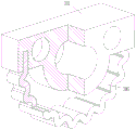
FIG. 1 is a schematic view of the construction of the inventive stretcher in a contracted state;
FIG. 2 is a schematic view of the clothes hanger of the present invention in a deployed state;
FIG. 3 is a front internal view of the inventive stretchy hanger;
FIG. 4 is a schematic view of the reverse internal construction of the garment stay of the present invention;
FIG. 5 is an enlarged view of a portion of FIG. 4 at A;
FIG. 6 is a front view of the invention stretchy hanger;
FIG. 7 is a rear elevational view of the present invention stretchy hanger;
FIG. 8 is a partial enlarged view at B in FIG. 4;
FIG. 9 is a schematic structural view of a toothed engagement block of the present invention;
FIG. 10 is a schematic view of the structure of the toothed connecting block of the present invention;
in the figure: the hook comprises a hook 1, a fixing block 2, a rectangular sliding groove 21, an angle adjusting component 3, a tooth-shaped meshing block 31, a pressing rod 32, a first spring 33, a tooth-shaped connecting block 34, a first gear tooth 341, a semicircular notch 342, a rectangular through groove 343, a first rotating pin 35, a tooth-shaped elastic metal plate 36, a first support rod 4, a rectangular sinking groove 41, a buckle 42, a second support rod 5, a ventilation diversion groove 51, a first elastic extrusion bump 61 and a second elastic extrusion bump 62.
Detailed Description
In order to make the technical means, the creation characteristics, the achievement purposes and the effects of the invention easy to understand, the invention is further described with the specific embodiments.
As shown in fig. 1 to 7, a clothes hanger capable of arbitrarily changing the angle of a stay bar comprises a hook 1, a fixed block 2, an angle adjusting component 3, a first stay bar 4 and a second stay bar 5; the upper end of the fixed block 2 is connected with the lower end of the hook 1 through threads; the lower end of the fixed block 2 is provided with an open notch; a rectangular sliding groove 21 is arranged above the notch; the angle adjusting component 3 is arranged in a cavity formed by the notch and the rectangular sliding groove 21; the angle adjusting component 3 is used for adjusting the angle of the first support rod 4; the first support rods 4 are arranged below the notches in a left-right symmetrical mode; a rectangular sinking groove 41 is formed in the outer side surface of the first support rod 4; the second support rod 5 is arranged in the rectangular sinking groove 41; one end of the second support rod 5 is hinged with the lower end of the first support rod 4; wherein,
the angle adjusting component 3 comprises a tooth-shaped meshing block 31, a pressing rod 32, a first spring 33, a tooth-shaped connecting block 34 and a first rotating pin 35; the upper end surface of the tooth-shaped meshing block 31 is attached to the top surface of the rectangular sliding chute 21; the lower end of the tooth-shaped meshing block 31 is provided with gear teeth; one side of the tooth-shaped meshing block 31 is fixedly connected with the pressing rod 32; the pressing rod 32 is connected in a mounting hole on the side wall of the fixed block 2 in a sliding manner; a counter bore is arranged on the end face of the other side of the tooth-shaped meshing block 31; the first spring 33 is arranged in the counter bore; one end of the first spring 33 is abutted in the counter bore; the other end of the first spring 33 abuts against the side wall of the fixed block 2; the lower end of the tooth-shaped meshing block 31 is meshed with two symmetrically arranged tooth-shaped connecting blocks 34; the two toothed connecting blocks 34 are not meshed with each other; a first gear tooth 341 is arranged at the upper end of the tooth-shaped connecting block 34; a semicircular notch 342 is formed in the upper end of the tooth-shaped connecting block 34; the semicircular notch 342 is arranged on one side of the first gear tooth 341; the tooth-shaped connecting block 34 is rotatably connected to the fixed block 2 through the first rotating pin 35; the lower end of the tooth-shaped connecting block 34 is fixedly connected with the upper end of the first support rod 4.
When the clothes hanger works, a user presses the pressing rod 32 through fingers to push the tooth-shaped meshing block 31 to slide along the rectangular sliding groove 21, so that the tooth-shaped meshing block 31 is pushed to one side corresponding to the semicircular notch 342, gear teeth on the tooth-shaped meshing block 31 are disengaged from gear teeth 341 on the tooth-shaped connecting block 34, the user can freely adjust the swing angle of the first support rod 4, the user can enable the first support rod 4 to be better attached to the model of clothes by adjusting the swing angle of the first support rod 4, and the problem that the clothes deform due to the fact that the support angle of the first support rod 4 is not matched with the model of the clothes is solved; after the user adjusts the swing angle of the first stay bar 4, the finger pressing the pressing rod 32 is released, and then under the action of the force of the first spring 33, the tooth-shaped meshing block 31 slides towards one side of the first gear tooth 341, so that the gear tooth on the tooth-shaped meshing block 31 is meshed with the first gear tooth 341, the rotation of the tooth-shaped connecting block 34 is limited through the meshing force between the gear teeth, the swing of the first stay bar 4 is limited, and the first stay bar 4 is kept in an adjusted state.
When the clothes hanger is used, a user inserts the first support rod 4 in a contracted state into clothes from the neckline of the clothes, then after pressing the press rod 32, two first support rods 4 are unfolded for a certain angle according to the type of the clothes, so that the first support rod 4 is attached to the inner side of the clothes, then the press rod 32 is loosened, so that the first support rod 4 is locked, the first support rod 4 is matched with the type of the clothes, the problem that the clothes deform due to the fact that the supporting angle of the first support rod 4 is not matched with the type of the clothes is solved, and the supporting effect of the clothes after the clothes are supported is improved; especially, the clothes ironing machine has better effect on the clothes ironed by the ironing machine and the clothes needing to be held up for a long time.
Through the articulated No. two vaulting poles 5 of lower extreme at a vaulting pole 4 for clothes hanger can enough realize propping up adult's clothes, can also realize propping up children's clothes through contracting No. two vaulting poles 5 in rectangle heavy groove 41, and then has improved clothes hanger's application scope, and then has improved user's result of use.
As shown in fig. 6 and 9, the gear teeth at the lower end of the tooth-shaped engaging block 31 are of a split structure; the lower end of the tooth-shaped meshing block 31 is provided with a tooth-shaped elastic metal plate 36; two ends of the tooth-shaped elastic metal plate 36 are fixedly connected in a rectangular groove on the lower end face of the tooth-shaped meshing block 31; the tooth-shaped elastic metal plate 36 is integrally bent into a semi-circular arc shape; the tooth-shaped elastic metal plate 36 is partially bent into a tooth-shaped structure; the tooth-shaped structure on the tooth-shaped elastic metal plate 36 is engaged with the first gear tooth 341.
In the working process, the gear teeth on the tooth-shaped meshing block 31 and the first gear teeth 341 on the tooth-shaped connecting block 34 are continuously meshed and disconnected, so that the gear teeth on the tooth-shaped meshing block 31 and the first gear teeth 341 on the tooth-shaped connecting block 34 are easily abraded, and the service life of the clothes hanger is further shortened; the gear teeth at the lower end of the tooth-shaped meshing block 31 are of a split structure, the gear teeth used for meshing are replaced by the tooth-shaped elastic metal plate 36, and then when the tooth-shaped elastic metal plate 36 meshes with the first gear teeth 341, the abrasion generated by extrusion between the tooth-shaped elastic metal plate 36 and the first gear teeth 341 can be reduced through the deformation of the tooth-shaped elastic metal plate 36, and the tooth-shaped elastic metal plate 36 can be meshed with the first gear teeth 341 more easily, so that the meshing can be completed more quickly and smoothly, the abrasion generated in the meshing process of the tooth-shaped elastic metal plate 36 and the first gear teeth 341 is further reduced, and the service life of the clothes hanger is prolonged.
As shown in fig. 9 and 10, the teeth of the tooth-shaped structure on the tooth-shaped elastic metal plate 36 are arc-shaped teeth; the first gear teeth 341 are arc-shaped teeth; a chamfer is arranged on one side of the first gear tooth 341 close to the semicircular notch 342.
The gear teeth and the first gear teeth 341 of the tooth-shaped elastic metal plate 36 are arc-shaped teeth, and a chamfer is arranged on one side of the first gear teeth 341 close to the semicircular notch 342, so that the arc-shaped teeth on the tooth-shaped elastic metal plate 36 can be extruded by the chamfer of the first gear teeth 341 when the tooth-shaped elastic metal plate 36 is meshed with the first gear teeth 341 to deform the tooth-shaped elastic metal plate 36, the arc-shaped teeth on the tooth-shaped elastic metal plate 36 are meshed with the arc-shaped teeth of the first gear teeth 341 more smoothly, the abrasion of the tooth-shaped elastic metal plate 36 and the first gear teeth 341 in the meshing process is further reduced, and the service life of the clothes hanger is prolonged.
As shown in fig. 5, 7 and 10, a rectangular through slot 343 is disposed on one side of the toothed connecting block 34 close to the semicircular notch 342; a buckle 42 is arranged on the upper end face of the first support rod 4; the buckle 42 penetrates through the rectangular through groove 343 and then is connected with the tooth-shaped connecting block 34 in a clamping manner.
As shown in fig. 6 and 7, a hinge point at one end of the second brace 5 is eccentrically arranged; the thickness of the second brace rod 5 is smaller than the depth of the rectangular sinking groove 41; the second brace rod 5 keeps a height difference with the rectangular sinking groove 41 in a contraction state; a ventilation diversion trench 51 is formed in the side face, close to the first support rod 4, of the second support rod 5 in the contraction state; the ventilation diversion trench 51 penetrates through the second support rod 5.
Through the eccentric arrangement of the hinge point of the second support rod 5, when the second support rod 5 is contracted in the rectangular sinking groove 41, a certain distance is reserved between the upper surface of the second support rod 5 and the upper surface of the first support rod 4, so that air flow exists between clothes and the first support rod 4, the condition that local drying cannot be carried out due to the fact that air does not circulate at the position where the clothes are in contact with the first support rod 4 is prevented, and the overall drying efficiency of the clothes is further ensured; guarantee simultaneously when No. two vaulting pole 5 expandes, No. two vaulting pole 5 upper surface can with the upper surface parallel and level of vaulting pole 4, and then guarantee to prop up the roughness of clothes.
The ventilation guide grooves 51 are formed in the second support rod 5, so that when the second support rod 5 is contracted in the rectangular sinking groove 41, the rectangular sinking groove 41 below the second support rod 5 can be kept in circulation, water drops dropping on clothes can slide down along the rectangular sinking groove 41 conveniently, and the clothes airing efficiency is improved; when No. two vaulting pole 5 expandes simultaneously, ventilation guiding gutter 51 on No. two vaulting pole 5 can make to have the air flow between clothes and No. two vaulting pole 5, and then prevents that the position of clothes and No. two vaulting pole 5 contact from leading to the condition that the part can't dry because the air does not circulate, and then has guaranteed the holistic sunning efficiency of clothes.
As shown in fig. 6 to 8, blind mounting holes are formed in the side walls of the lower end of the rectangular sink 41; the mounting blind holes are symmetrically arranged on the side walls at two sides of the rectangular sinking groove 41; an elastic extrusion lug is arranged in the mounting blind hole; the elastic extrusion convex block extends out of the mounting blind hole.
Through set up elasticity extrusion arch on the lateral wall at rectangle heavy groove 41, and then after No. two vaulting poles 5 expand, extrude the side of No. two vaulting poles 5 through elasticity extrusion arch, and then make No. two vaulting poles 5 angle that remain stable under the effect of the bellied frictional force of elasticity extrusion, and through pulling No. two vaulting poles 5 manually and then realize the arbitrary regulation to No. two vaulting pole 5 angles, No. two vaulting poles 5 swing different angles can satisfy the clothes of different styles of user's string airing, for example during sunning suspender skirt and brassiere, through having set up certain angle with No. two vaulting poles 5, and then can guarantee that the clothes of string airing can not drop, and then improved user's result of use.
As shown in fig. 6 to 8, two mounting blind holes are provided on the side surface of one side of the rectangular sink 41; one of the mounting blind holes is arranged close to the bottom of the rectangular sinking groove 41, and a first elastic extrusion bump 61 is arranged in the mounting blind hole close to the bottom of the rectangular sinking groove 41; the other mounting blind hole is far away from the bottom of the rectangular sinking groove 41, and a second elastic extrusion bump 62 is arranged in the mounting blind hole far away from the bottom of the rectangular sinking groove 41; the height of the first elastic pressing projection 61 is greater than that of the second elastic pressing projection 62.
The first elastic extrusion convex block 61 and the second elastic extrusion convex block 62 are arranged, so that the second support rod 5 can realize multi-stage adjustment, the capability of the clothes stretcher to adapt to different clothes styles is improved, and the application range of the clothes stretcher is further improved; through the height that highly is greater than No. two elasticity extrusion lug 62 that sets up an elasticity extrusion lug 61, and then make No. two vaulting poles 5 guarantee to have angle modulation function again can be fine keep the parallel and level with a vaulting pole 4, and then guarantee that No. two vaulting poles 5 all can satisfy the operation requirement under multiple service environment, and then improve the application scope of clothes hanger.
When the clothes hanger works, a user presses the pressing rod 32 through fingers to push the tooth-shaped meshing block 31 to slide along the rectangular sliding groove 21, so that the tooth-shaped meshing block 31 is pushed to one side corresponding to the semicircular notch 342, gear teeth on the tooth-shaped meshing block 31 are disengaged from gear teeth 341 on the tooth-shaped connecting block 34, the user can freely adjust the swing angle of the first support rod 4, the user can enable the first support rod 4 to be better attached to the model of clothes by adjusting the swing angle of the first support rod 4, and the problem that the clothes deform due to the fact that the support angle of the first support rod 4 is not matched with the model of the clothes is solved; after the user adjusts the swing angle of the first stay bar 4, the finger pressing the pressing rod 32 is released, and then under the action of the force of the first spring 33, the tooth-shaped meshing block 31 slides to one side of the first gear tooth 341, so that the gear tooth on the tooth-shaped meshing block 31 is meshed with the first gear tooth 341, the rotation of the tooth-shaped connecting block 34 is limited through the meshing force between the gear teeth, the swing of the first stay bar 4 is limited, and the first stay bar 4 is kept in an adjusted state; when the clothes hanger is used, a user inserts the first support rod 4 in a contracted state into clothes from the neckline of the clothes, then after pressing the press rod 32, two first support rods 4 are unfolded for a certain angle according to the type of the clothes, so that the first support rod 4 is attached to the inner side of the clothes, then the press rod 32 is loosened, so that the first support rod 4 is locked, the first support rod 4 is matched with the type of the clothes, the problem that the clothes deform due to the fact that the supporting angle of the first support rod 4 is not matched with the type of the clothes is solved, and the supporting effect of the clothes after the clothes are supported is improved; especially, the clothes ironed by the ironing machine and the clothes needing to be supported for a long time have better effect; through the articulated No. two vaulting poles 5 of lower extreme at a vaulting pole 4 for clothes hanger can enough realize propping up adult's clothes, can also realize propping up children's clothes through contracting No. two vaulting poles 5 in rectangle heavy groove 41, and then has improved clothes hanger's application scope, and then has improved user's result of use.
While the present invention has been described with reference to the embodiments shown in the drawings, the present invention is not limited to the embodiments, which are illustrative and not restrictive, and it will be apparent to those skilled in the art that various changes and modifications can be made therein without departing from the spirit and scope of the invention as defined in the appended claims.