CN111538269B - A non-contact button sensor unit and triggering method - Google Patents
A non-contact button sensor unit and triggering method Download PDFInfo
- Publication number
- CN111538269B CN111538269B CN202010345538.1A CN202010345538A CN111538269B CN 111538269 B CN111538269 B CN 111538269B CN 202010345538 A CN202010345538 A CN 202010345538A CN 111538269 B CN111538269 B CN 111538269B
- Authority
- CN
- China
- Prior art keywords
- electrode
- trigger
- capacitance
- button
- hovering
- Prior art date
- Legal status (The legal status is an assumption and is not a legal conclusion. Google has not performed a legal analysis and makes no representation as to the accuracy of the status listed.)
- Active
Links
Images





Classifications
-
- G—PHYSICS
- G05—CONTROLLING; REGULATING
- G05B—CONTROL OR REGULATING SYSTEMS IN GENERAL; FUNCTIONAL ELEMENTS OF SUCH SYSTEMS; MONITORING OR TESTING ARRANGEMENTS FOR SUCH SYSTEMS OR ELEMENTS
- G05B19/00—Program-control systems
- G05B19/02—Program-control systems electric
- G05B19/04—Program control other than numerical control, i.e. in sequence controllers or logic controllers
- G05B19/042—Program control other than numerical control, i.e. in sequence controllers or logic controllers using digital processors
- G05B19/0423—Input/output
-
- H—ELECTRICITY
- H03—ELECTRONIC CIRCUITRY
- H03K—PULSE TECHNIQUE
- H03K17/00—Electronic switching or gating, i.e. not by contact-making and –breaking
- H03K17/94—Electronic switching or gating, i.e. not by contact-making and –breaking characterised by the way in which the control signals are generated
- H03K17/965—Switches controlled by moving an element forming part of the switch
- H03K17/968—Switches controlled by moving an element forming part of the switch using opto-electronic devices
-
- G—PHYSICS
- G05—CONTROLLING; REGULATING
- G05B—CONTROL OR REGULATING SYSTEMS IN GENERAL; FUNCTIONAL ELEMENTS OF SUCH SYSTEMS; MONITORING OR TESTING ARRANGEMENTS FOR SUCH SYSTEMS OR ELEMENTS
- G05B2219/00—Program-control systems
- G05B2219/20—Pc systems
- G05B2219/24—Pc safety
- G05B2219/24215—Scada supervisory control and data acquisition
Landscapes
- Physics & Mathematics (AREA)
- General Physics & Mathematics (AREA)
- Engineering & Computer Science (AREA)
- Automation & Control Theory (AREA)
- Switches That Are Operated By Magnetic Or Electric Fields (AREA)
- Electronic Switches (AREA)
Abstract
一种非接触按钮传感器单元,电容传感器为一个凸字形布置的中心电极和外围电极,电容数字转换电路测量人体手指接近后的中心电极和外围电极的自电容和互电容,计算判断手指是否进入区域范围及停留时间以及虚拟点击,以此控制模块输出该按钮的控制逻辑信号;借助这个传感器单元构成的按钮,检测人体手指接近某个中心电极上部有效悬停触发区域范围,通过声光反馈控制电路提供人体手指进入某个中心电极上部有效悬停触发区域范围的三态响应;本发明创造提供了结构设计合理,有效抵御各种干扰,充分利用电容检测的低成本和成熟的CDC芯片技术,为卫生敏感提供了可以普及推广的商业化技术解决方案。

A non-contact button sensor unit, the capacitive sensor is a central electrode and peripheral electrode arranged in a convex shape, the capacitance digital conversion circuit measures the self-capacitance and mutual capacitance of the central electrode and the peripheral electrode after the human finger approaches, and calculates and judges whether the finger enters the area Range and dwell time and virtual click, so that the control module outputs the control logic signal of the button; with the help of the button composed of this sensor unit, it detects that the human finger is close to the range of the effective hovering trigger area on the upper part of a certain central electrode, and controls the circuit through the acousto-optic feedback Provides a tri-state response for human fingers entering the effective hovering trigger area on the upper part of a certain central electrode; the invention provides reasonable structural design, effective resistance to various interferences, and full use of low-cost and mature CDC chip technology for capacitance detection. Sanitation Sensitive provides a commercialized technical solution that can be popularized.
Description
技术领域technical field
本发明创造涉及公共卫生的按钮,特别是考虑卫生敏感下的感应按钮,例如水龙头、抽水马桶的冲水按钮、开水器的防水按钮等,尤其是电梯的按钮设计。The present invention creates buttons related to public health, especially sensor buttons considering hygiene sensitivity, such as faucets, flush buttons for toilets, waterproof buttons for water boilers, etc., especially button designs for elevators.
背景技术Background technique
新冠肺炎疫情的出现,加上季节性流感现等情况,对于电梯的消毒,特别是按钮开关的消毒,面临巨大的工作量,甚至难以实现病毒的消毒处理,为此社会上出现对接近感应按钮的需求,因为直接接触公共区域的按钮开关,例如电梯楼层选择和开关门的按钮,卫生间的冲水开关,公共饮用水开关等容易导致感染传染性疾病,而非接触式的按钮可以避免这样的风险。With the emergence of the new crown pneumonia epidemic, coupled with the current situation of seasonal flu, the disinfection of elevators, especially the disinfection of button switches, is faced with a huge workload, and it is even difficult to realize the disinfection of viruses. Because direct contact with button switches in public areas, such as elevator floor selection and door switch buttons, toilet flush switches, public drinking water switches, etc., can easily lead to infectious diseases, and non-contact buttons can avoid such problems risk.
对于人体的接近,特别是操作电梯按钮的手指的接近,有很多技术方案可以采用,包括摄像头、红外或射频等技术,例如中国201480079328.5号专利;但电容感应是各种感应方案中成本最低的方案。For the proximity of the human body, especially the proximity of fingers operating elevator buttons, there are many technical solutions that can be used, including camera, infrared or radio frequency technologies, such as China Patent No. 201480079328.5; but capacitive sensing is the lowest cost solution among various sensing solutions .
对于目前公共区域大量使用的光电感应水龙头,以及冲水马桶的人体感应控制,除了感应控制器成本比较高以外,还存在很多难以自己掌控随心所欲的问题,例如清洗衣服及用毛巾洗脸时,感应龙头难以正常工作,使用者需要一种十分接近实体水龙头控制的感应控制技术。For the photoelectric sensor faucets widely used in public areas and the human sensor control of flushing toilets, in addition to the relatively high cost of the sensor controller, there are still many problems that are difficult to control by yourself. For example, when washing clothes and washing the face with a towel, the sensor faucet It is difficult to work normally, and users need a sensory control technology that is very close to the control of a physical faucet.
中国专利201480079328公开了一种利用手势控制电梯的技术方案在其说明书中,提到了类似摄像等技术来记录手势,包括预先设置手势,其主要的技术构成是先记录甚至定制手势,把这些手势的数据记录在系统中形成手势库,然后在侦察到一种手势命令后,与手势库进行对比,判断出手势的含义,有点类似目前已经开始普及起来的人脸设别技术;该技术需要的硬件设备多且昂贵,另一方面,使用者的定制也是非常困难的,由于人体手势及动作方式千奇百怪,在准确判断识别和抗干扰这二个矛盾方面,该技术存在相当大的挑战,目前市面上没有出现这个产品也间接说明该技术的难度。Chinese patent 201480079328 discloses a technical solution for using gestures to control elevators. In its specification, it mentions techniques such as photography to record gestures, including preset gestures. The data is recorded in the system to form a gesture library, and then after a gesture command is detected, it is compared with the gesture library to determine the meaning of the gesture, which is a bit similar to the face recognition technology that has become popular at present; the hardware required for this technology There are a lot of equipment and expensive. On the other hand, user customization is also very difficult. Due to the various gestures and movements of the human body, this technology has considerable challenges in accurately judging the two contradictions of recognition and anti-interference. The absence of this product also indirectly shows the difficulty of the technology.
申请号201610551225.5,提出带有凹槽的电容式接近按钮,电容式接近按钮设置在凹槽底部,通过阈值设计人手指必须伸进凹槽内才能触发接近按钮,该申请并未披露电容接近按钮的具体电容测量方法,该方案存在存在着使用者的手指伸进凹槽容易触碰凹槽内壁的缺陷,特别是在电梯这种灯光相对昏暗及人员可能拥挤的环境中,同时,手势感应的使用者不太可能保证其动作的手指能够完全受控而不会产生抖动,否则就失去卫生敏感的意义;另外一方面,该专利对于温湿度等环境因素对设定阈值的影响也无法避免。Application No. 201610551225.5 proposes a capacitive proximity button with a groove. The capacitive proximity button is set at the bottom of the groove. The human finger must be inserted into the groove to trigger the proximity button through the threshold design. The application does not disclose the capacitive proximity button. Specifically, the capacitance measurement method has the disadvantage that the user's fingers can easily touch the inner wall of the groove when the user's finger is inserted into the groove, especially in an environment such as an elevator where the light is relatively dim and people may be crowded. At the same time, the use of gesture sensing It is impossible for the operator to ensure that the fingers of the movement can be completely controlled without shaking, otherwise the meaning of hygienic sensitivity will be lost; on the other hand, the influence of environmental factors such as temperature and humidity on the set threshold cannot be avoided in this patent.
美国专利US7498822公开了一种电容感应人体手指接近的方案,也是采用类似的凹形设计的电容电极,同样存在上述问题,如果设法避免上述问题,按照我们的实验来看,需要让手指与开关壁有2cm以上的距离作为设计基础,那么,凹形电极设置的开关,最少需要5cm的内径设计,使得电梯众多开关按钮的排布成为挑战;另外,该专利披露了单纯模拟电路来测量电容的技术方案,并且还进一步为了消除相互串扰,特意采用等电势的办法和采用差分放大器等,但经过我们反复实验,人体手指对于电梯环境下设计的一个电极在防止无意触碰的安全距离下,所能够产生的电容值变化大体是10ff量级的,单纯模拟电路很难在测量与消除环境影响间取得较好的效果,所需要的器件成本也很高。另外,凹形电极布置的结构将增加悬停按钮结构成型的复杂度,导致加工成本的上升,并影响悬停按钮的美观和今后电梯的清洁消毒工作。美国专利US7498822仅仅采用测量自电容的方法,而排斥互电容的测量方法,没有利用互电容抗干扰能力强的优点,提高悬停按钮的性能,此外,该专利由于没有悬停按钮必须的声光反馈系统,会给操作者造成使用悬停按钮的困惑和不便。U.S. Patent No. 7,498,822 discloses a scheme for capacitive sensing of the proximity of human fingers, which also adopts a similar concave design of capacitive electrodes. The above problems also exist. If we try to avoid the above problems, according to our experiments, we need to make the fingers and the switch wall With a distance of more than 2cm as the design basis, the switch set by the concave electrode needs to be designed with an inner diameter of at least 5cm, which makes the arrangement of many switch buttons in the elevator a challenge; in addition, the patent discloses the technology of measuring capacitance with pure analog circuits In addition, in order to eliminate mutual crosstalk, equipotential methods and differential amplifiers are specially used. However, after repeated experiments, we have found that a human finger can withstand a safe distance from an electrode designed in an elevator environment to prevent unintentional touch. The resulting capacitance value change is generally on the order of 10ff. It is difficult for a pure analog circuit to achieve a good effect between measurement and elimination of environmental impact, and the cost of the required components is also high. In addition, the structure of the concave electrode arrangement will increase the complexity of the structure of the hovering button, resulting in an increase in processing costs, and affecting the appearance of the hovering button and the cleaning and disinfection of the elevator in the future. U.S. Patent US7498822 only uses the method of measuring self-capacitance, and the measurement method of repelling mutual capacitance does not take advantage of the advantages of strong anti-interference ability of mutual capacitance to improve the performance of the hovering button. In addition, this patent does not have the sound and light necessary for the hovering button Feedback systems that confuse and inconvenience the operator using hover buttons.
现有成熟技术的电容数字转换电路(CDC),例如DAI7142、ADI7147,采用Δ-∑调制方式通过多次对被测电容进行充放电并于参考电容比较的方法(参见:US Patent Number:5,134,401)直接将被测电容值转换成数字值,可以将对电容的测量灵敏度提高到1ff级别,容易满足测量系统在安全距离下对电容测量灵敏度的要求,特别是,这些芯片的设计具有多个通道,使得电路设计简单方便,从而有效降低成本和安装难度。Capacitance-to-digital conversion circuits (CDC) with mature technology, such as DAI7142 and ADI7147, use the method of Δ-Σ modulation to charge and discharge the measured capacitor multiple times and compare it with the reference capacitor (see: US Patent Number: 5,134,401) Directly converting the measured capacitance value into a digital value can increase the measurement sensitivity of capacitance to 1ff level, which can easily meet the requirements of the measurement system for capacitance measurement sensitivity at a safe distance. In particular, these chips are designed with multiple channels, The circuit design is simple and convenient, thereby effectively reducing the cost and installation difficulty.
相比于摄像头、红外或射频等技术,在检测人体接近方面,电容检测技术具有电路结构简单,成本低廉等特点,但同时也存在着电容变化不大而对检测分辨率的高要求,还有电容检测极容易受到环境的影响。Compared with technologies such as camera, infrared or radio frequency, capacitance detection technology has the characteristics of simple circuit structure and low cost in detecting the approach of human body. Capacitance sensing is extremely susceptible to environmental influences.
一般而言,电容电极构成的自电容以及电极间构成的互电容,都会受到接近的手指的影响,有效利用这些影响同时考虑自电容测量和互电容测量的不同特性来检测手指接近程度,同步排除身体其它部位、误动作、环境对电极电容测量的影响,目前还不是很容易的。Generally speaking, the self-capacitance formed by the capacitive electrodes and the mutual capacitance formed between the electrodes will be affected by the approaching fingers. Effectively use these influences and consider the different characteristics of the self-capacitance measurement and mutual capacitance measurement to detect the proximity of the fingers and exclude them simultaneously. The influence of other parts of the body, misoperation, and environment on electrode capacitance measurement is not very easy at present.
对于采用电容感应人体手指接近的悬停按钮,需要充分考虑使用者的不同感应习惯,同时要防止身体其它部位的感应及清洁工清洁时的动作带来的误触发,做到精确判断,在电梯这样的环境下,是相当困难的,所以,至今没有见到商业化的产品问世。For the hovering button that adopts capacitive sensing human finger approaching, it is necessary to fully consider the different sensing habits of the user, and at the same time, it is necessary to prevent false triggering caused by the sensing of other parts of the body and the action of the cleaner during cleaning, so as to achieve accurate judgment. Under such an environment, it is quite difficult, so no commercial products have been seen so far.
发明内容Contents of the invention
本发明的目的在于克服现有技术的不足,创造一种特别适合悬停按钮特点的电容传感器,再配合成熟的电容数字转换技术,充分利用了CDC电路对杂散分布电容免疫的特长,采用了自电容和互电容相结合的测量方法,加上三态声光反馈电路,考虑人体手指接近的特点,避免各种不同的干扰,精确判断手指的接近动作来触发按钮,不但适合电梯的配套,而且适合现有电梯按钮的改造,同样适用于其它卫生敏感的按钮控制,整体成本容易被商业化所接受。本发明创造出一个对应一个按钮的电容传感器单元,非接触按钮传感器单元,包括:电源电路,电容传感器,电容数字转换电路,控制模块,声光反馈控制电路,通讯电路;The purpose of the present invention is to overcome the deficiencies of the prior art, create a capacitive sensor that is particularly suitable for the characteristics of the hovering button, and then cooperate with the mature capacitance-to-digital conversion technology to make full use of the special feature of the CDC circuit that is immune to stray distributed capacitance. The measurement method combining self-capacitance and mutual capacitance, plus three-state acousto-optic feedback circuit, considers the characteristics of human fingers approaching, avoids various interferences, and accurately judges the approaching action of fingers to trigger the button. It is not only suitable for elevators, Moreover, it is suitable for the transformation of existing elevator buttons, and is also suitable for other hygienic sensitive button controls, and the overall cost is easily accepted by commercialization. The present invention creates a capacitive sensor unit corresponding to a button, a non-contact button sensor unit, including: a power supply circuit, a capacitive sensor, a capacitive digital conversion circuit, a control module, an acousto-optic feedback control circuit, and a communication circuit;
所述电容传感器由一组或者多组电极构成,每组电极包括至少一个中心电极、至少一个围绕中心电极设置的外围电极,中心电极凸出外围电极1.1-8.8mm的高度;The capacitive sensor is composed of one or more sets of electrodes, each set of electrodes includes at least one central electrode, at least one peripheral electrode arranged around the central electrode, and the central electrode protrudes from the peripheral electrode by a height of 1.1-8.8mm;
所述电容数字转换电路包括电容激励信号电路,所述电容激励信号电路产生高频方波激励信号;The capacitance-to-digital conversion circuit includes a capacitance excitation signal circuit, and the capacitance excitation signal circuit generates a high-frequency square wave excitation signal;
上述中心电极、外围电极均连接电容数字转换电路,检测该组中心电极、外围电极感应人体手指接近后的自电容和互电容;The above-mentioned central electrodes and peripheral electrodes are all connected to a capacitance-to-digital conversion circuit to detect the self-capacitance and mutual capacitance of the group of central electrodes and peripheral electrodes after sensing the approach of human fingers;
所述电容数字转换电路与所述控制模块连接,所述控制模块依据人体手指指向所述中心电极上部的有效悬停触发区域范围及在此范围内的驻留时间和/或虚拟点击输出该按钮的触发逻辑信号。The capacitance-to-digital conversion circuit is connected to the control module, and the control module outputs the button according to the effective hovering trigger area range of the human finger pointing to the upper part of the center electrode and the dwell time within this range and/or a virtual click trigger logic signal.
控制模块可以采用MCU,随着电子技术的不断发展,都出现了电容数字转换电路CDC与控制模块MCU合二为一的芯片,如CYPRESS的PSoC 4100SPlus系列等但其功能组成如故。The control module can use MCU. With the continuous development of electronic technology, a chip that combines the capacitance-to-digital conversion circuit CDC and the control module MCU has appeared, such as the PSoC 4100SPlus series of CYPRESS, but its functional composition remains the same.
同时,在上述的传感器单元基础上,本发明的按钮触发方法是通过电容传感器检测和计算人体手指进入某个中心电极上部有效悬停触发区域,通过声光反馈控制电路提供人体手指进入所述有效悬停触发区域的预触发响应;At the same time, on the basis of the above-mentioned sensor unit, the button triggering method of the present invention detects and calculates that the human finger enters the effective hovering trigger area on the upper part of a certain central electrode through the capacitive sensor, and provides the human finger to enter the effective hovering trigger area through the acousto-optic feedback control circuit. Pre-trigger response for hover trigger area;
如果人体手指进入比有效悬停触发区域更接近中心电极的快速触发区域,则直接输出人体手指所指按钮的触发逻辑信号并且同时声光反馈控制电路给予触发状态响应;否则,持续检测人体手指是否停留在所述有效悬停触发区域,如果是并且超过设定的悬停时间,和/或检测到人体手指在有效悬停触发区域内有悬空的点击动作,即虚拟点击动作,输出人体手指所指按钮的触发信号并且同时声光反馈控制电路给予触发状态响应;如果在设定的悬停时间内检测到手指离开了所述有效悬停触发区域,则返回无触发状态。If the human finger enters the fast trigger area closer to the central electrode than the effective hover trigger area, the trigger logic signal of the button pointed by the human finger is directly output and the acousto-optic feedback control circuit responds to the trigger state at the same time; otherwise, it continuously detects whether the human finger is Staying in the effective hovering trigger area, if it is and exceeds the set hovering time, and/or detects that the human finger has a floating click action in the effective hovering trigger area, that is, a virtual click action, and outputs the click action of the human finger. The trigger signal of the finger button and at the same time the acousto-optic feedback control circuit gives a trigger state response; if it is detected that the finger leaves the effective hover trigger area within the set hover time, it will return to the no trigger state.
特别是,本发明创造的电极布置,还有以下优点:第一、从根本上避免了手指接触侧壁的风险;第二、无需考虑侧壁安全距离,从而有效的缩小了悬停按钮的直径,可以将整个按钮外径控制在3CM以下,可以轻易满足多排按钮的空间布局要求;第三、通用积木化设计,便于大规模量产;第四、由于不需要手指插入凹容器,多排凸结构悬停按钮表面可以统一用平面装饰材料,例如玻璃、亚克力或其他非导电材料进行装饰,而凸结构本身可以用一层或两层PCB板低成本实现。In particular, the electrode arrangement created by the present invention has the following advantages: first, the risk of finger contacting the side wall is fundamentally avoided; second, there is no need to consider the safety distance of the side wall, thereby effectively reducing the diameter of the hovering button , the outer diameter of the entire button can be controlled below 3CM, which can easily meet the spatial layout requirements of multiple rows of buttons; third, the general building block design is convenient for mass production; fourth, since there is no need to insert fingers into the concave container, multiple rows The surface of the hover button with a convex structure can be uniformly decorated with flat decorative materials, such as glass, acrylic or other non-conductive materials, and the convex structure itself can be realized with one or two layers of PCB at low cost.
附图说明Description of drawings
图1为发明创造的使用状态示意图,也表示了手指相对于按钮的接近状态,图中实线和虚线分别表示了一种人体手指指向按钮的不同角度状态。Fig. 1 is a schematic view of the use state of the invention, which also shows the approach state of the finger relative to the button. The solid line and the dotted line in the figure respectively represent a different angle state of a human finger pointing to the button.
图2为本发明创造的传感器立体图,包括图2-1是人体手指水平方向接近电容电极的示意图;图2-2是人体手指45°方向接近电容电极的示意图;图2-3人体手指垂直方向接近电容电极的示意图;图2-4是人体整个手掌接近电容电极的示意图。Fig. 2 is a three-dimensional view of the sensor created by the present invention, including Fig. 2-1, which is a schematic diagram of a human finger approaching a capacitor electrode in a horizontal direction; Fig. 2-2, a schematic diagram of a human finger approaching a capacitive electrode in a 45° direction; Fig. 2-3, a human finger vertical direction Schematic diagram of approaching the capacitive electrode; Figure 2-4 is a schematic diagram of the whole palm of the human body approaching the capacitive electrode.
图3,包括图3-1和图3-2,为本发明创造的人体手指及手掌在工作时与电容电极的位置关系以及所体现出的电容等效原理图,其中图3-2比图3-1更清晰表示出感应范围的示意图。Fig. 3, including Fig. 3-1 and Fig. 3-2, is the positional relationship between the fingers and palms of the human body and the capacitive electrodes during work created by the present invention and the schematic diagram of the equivalent capacitance shown, in which Fig. 3-2 is compared with Fig. 3-1 is a schematic diagram showing the sensing range more clearly.
图4为本发明创造的单个电容电极单元下电容传感器结构图,其中图4-1俯视地表达几个电容电极的相互关系,图4-2,4-3剖视地反映电容电极的布置示意图。Fig. 4 is a structure diagram of a capacitive sensor under a single capacitive electrode unit created by the present invention, wherein Fig. 4-1 expresses the interrelationships of several capacitive electrodes in a top view, and Fig. 4-2, 4-3 reflect the schematic diagram of the arrangement of capacitive electrodes in section .
图5为本发明创造涉及一组以上电极单元的电极布置示意图。Fig. 5 is a schematic diagram of electrode arrangement involving more than one set of electrode units in the present invention.
图6为本发明创造检测电容的时序安排示意图。FIG. 6 is a schematic diagram of timing arrangement for detecting capacitance of the present invention.
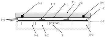
图7为类似于图4-2的单个按钮时电容电极设计与其它电路相结合的结构排布示意图;Figure 7 is a schematic diagram of the structural arrangement of the capacitive electrode design combined with other circuits when a single button is similar to Figure 4-2;
图8是电梯上下按钮/双按钮基本单元应用本发明创造的一个表达结构上布置的爆炸示意图。Fig. 8 is an exploded schematic diagram of an expression structure arrangement of the elevator up and down button/double button basic unit applied to the invention.
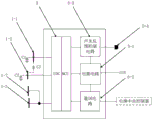
图9为本发明创造的电容电极测量及控制等原理图。Fig. 9 is a schematic diagram of the capacitive electrode measurement and control of the present invention.
图10是电梯内多排按钮设置上的电路结构示意图。Figure 10 is a schematic diagram of the circuit structure on the arrangement of multiple rows of buttons in the elevator.
图11包括图11-1、图11-2、图11-3、图11-4、图11-5、图11-6分别是中心电极和外围电极各种结构形式的示意图。Fig. 11 includes Fig. 11-1, Fig. 11-2, Fig. 11-3, Fig. 11-4, Fig. 11-5, and Fig. 11-6, which are schematic diagrams of various structural forms of the central electrode and the peripheral electrode, respectively.
图12系本发明创造判断手指接近与否等的系统流程图。Fig. 12 is a flow chart of the system for judging whether a finger is close or not, etc. according to the present invention.
图13,包括图13-1反映了手指对电极自电容的影响示意图及图13-2给出了此时的等效电路。Fig. 13, including Fig. 13-1, which shows the influence of the finger on the self-capacitance of the electrode, and Fig. 13-2, which shows the equivalent circuit at this time.
图14,包括图14-1反映了手指对二个电极间互电容的影响示意图及图14-2给出了此时的等效电路。Fig. 14 includes Fig. 14-1 which shows the influence of finger on the mutual capacitance between two electrodes and Fig. 14-2 which shows the equivalent circuit at this time.
图15是手指在有效悬停触发区域内作出虚拟点击动作后中心电容的电容值变化的曲线。FIG. 15 is a curve of the capacitance value change of the center capacitor after the finger makes a virtual click action in the effective hovering trigger area.
具体实施方式Detailed ways
本发明创造适用于卫生敏感场合按钮的手指接近来感应控制,下面主要以电梯按钮加以详细的介绍,通过这些介绍而成就的技术,同样适用其它卫生敏感的按钮控制。The present invention is suitable for finger approach sensing control of buttons in hygienic sensitive occasions. The elevator button will be introduced in detail below. The technology achieved through these introductions is also applicable to other hygienic sensitive button controls.
对于采用电容测量来计算判断手指接近电极的情况,有必要对电极的自电容和互电容的情况加以说明,结合图13和图14;电容检测人体接近的原理可以分为自电容检测和互电容检测两种方式,互电容的检测原理参见图13-1,当人体接近时,两个电极之间形成的互电容Cm的电场线被人体扰动导致互电容Cm电容值会发生变化,且该变化与人体接近两个电极的平均距离成正比,在其中一个电极施加激励信号,在另一电极接测量电路,即可检测互电容的变化值,其等效测量电路如图13-2所示,一般互电容测量距离较小,但抗干扰能力较强;自电容的检测原理参见图14-1,人体接近单个电极时,单个电极与人体之间会形成自电容Cs,该自电容Cs通过人体对大地的等效电容Ca接地,Cs与人体接近所述单个电极的距离成正比,人体对大地的等效电容Ca约为200PF,而自电容Cs的变化范围通常小于1PF,图14-2是测量自电容的等效电路,可以看出Ca和Cs是串联关系,依据串联电容公式,串联电容等效电容Cx=Ca*Cs/(Ca+Cs),因为Ca远大于Cf,所以份子Ca+Cs≈Ca,于是有Cx≈Ca*Cs/Ca=Cs,即可以将互电容Cs近似为所述单个电极对地的电容,因此测量自电容就等同于测量单个电极对地的电容,互电容与人体距单个电极的距离成正比关系;与互电容的激励信号和测量电路分别连接两个电极不同,自电容的激励信号与测量电路连接在同一个电极上,一般自电容测量距离较远,但抗干扰能力较弱;相反,互电容的测量距离相对受到电极布置的影响,相对小一点,但其抗干扰能力强。For the use of capacitance measurement to calculate and judge the situation of finger approaching the electrode, it is necessary to explain the self-capacitance and mutual capacitance of the electrode, combined with Figure 13 and Figure 14; the principle of capacitance detection of human body approach can be divided into self-capacitance detection and mutual capacitance There are two detection methods. The detection principle of mutual capacitance is shown in Figure 13-1. When the human body approaches, the electric field line of the mutual capacitance Cm formed between the two electrodes is disturbed by the human body, causing the capacitance value of the mutual capacitance Cm to change, and the change It is proportional to the average distance of the human body approaching the two electrodes. Apply an excitation signal to one of the electrodes and connect the measurement circuit to the other electrode to detect the change value of the mutual capacitance. The equivalent measurement circuit is shown in Figure 13-2. Generally, the mutual capacitance measurement distance is small, but the anti-interference ability is strong; the detection principle of self-capacitance is shown in Figure 14-1. When the human body is close to a single electrode, a self-capacitance Cs will be formed between the single electrode and the human body, and the self-capacitance Cs will pass through the human body. The equivalent capacitance Ca to the earth is grounded, Cs is proportional to the distance of the human body approaching the single electrode, the equivalent capacitance Ca of the human body to the earth is about 200PF, and the variation range of the self-capacitance Cs is usually less than 1PF, as shown in Figure 14-2 Measuring the equivalent circuit of self-capacitance, it can be seen that Ca and Cs are in series relationship. According to the series capacitance formula, the series capacitance equivalent capacitance Cx=Ca*Cs/(Ca+Cs), because Ca is much larger than Cf, so the molecule Ca+ Cs≈Ca, so Cx≈Ca*Cs/Ca=Cs, that is, the mutual capacitance Cs can be approximated as the capacitance of the single electrode to the ground, so measuring the self-capacitance is equivalent to measuring the capacitance of a single electrode to the ground, the mutual capacitance It is proportional to the distance from the human body to a single electrode; unlike the excitation signal of mutual capacitance and the measurement circuit connected to two electrodes, the excitation signal of self-capacitance is connected to the same electrode as the measurement circuit, and the measurement distance of self-capacitance is generally far away. But the anti-interference ability is weak; on the contrary, the measurement distance of mutual capacitance is relatively affected by the electrode layout, which is relatively small, but its anti-interference ability is strong.
对于电梯按钮,分三种情况,一是一个按钮的情况,二是上下二个按钮的情况,三是电梯轿厢里多个按钮的情况;For the elevator button, there are three cases, one is the case of one button, the other is the case of two buttons up and down, and the third is the case of multiple buttons in the elevator car;
对于电梯的使用者,利用手指从上下左右各个不同角度去触发某个按钮都是可能的,在接触式按钮开关的应用场景中,平行于按钮的方向,在360度范围内,人的手指无论从任何方向角接触按钮都应该触发开关,而在垂直于按钮的方向,手指从0至90度以任何角度接触按钮都应该触发开关,同样悬停按钮也应该满足与接触式按钮同样的方向和角度范围内可以有效触发开关的要求。图1中显示了人体手指接近按钮电极的三种状态,包括实线所示的平行进入,虚线所示的45°角度进入和垂直90°角度进入,图中4-1为按钮面板,1-1为中心电极,1-2为外围电极。本发明创造就是要让这三种手指的接近方式都能够得到响应。For elevator users, it is possible to use fingers to trigger a certain button from different angles up, down, left, and right. In the application scenario of a contact button switch, the direction parallel to the button is within 360 degrees. Touching the button from any direction angle should trigger the switch, and in the direction perpendicular to the button, finger touching the button at any angle from 0 to 90 degrees should trigger the switch, and the hovering button should also meet the same orientation and contact buttons. The requirement that the switch can be effectively triggered within the angular range. Figure 1 shows three states of the human finger approaching the button electrode, including the parallel entry shown by the solid line, the 45° angle entry and the vertical 90° angle entry shown by the dotted line, 4-1 in the figure is the button panel, 1- 1 is the central electrode, 1-2 is the peripheral electrode. The invention of the present invention is to allow the approaching manners of these three fingers to be responded to.
非接触按钮需要有效防止人体大面积接近悬停按钮时造成的误触发,包括电梯内人多时臂部或背部靠近或紧贴悬停按钮、清洁时手掌或拳头贴近悬停按钮等各种误触发的情形。要充分利用人体手掌伸出一个手指这种指向动作下,需要设计的电容电极有相当大的冗余量来加以区分。Non-contact buttons need to effectively prevent false triggers caused by a large area of the human body approaching the hover button, including various false triggers such as arms or backs approaching or clinging to the hover button when there are many people in the elevator, and palms or fists close to the hover button when cleaning. situation. To make full use of the pointing action of stretching out a finger in the palm of the human body, it is necessary to design capacitive electrodes with a considerable amount of redundancy to distinguish them.
图2表示了人体手指三个状态去触发按钮的示意图以及手掌接近按钮的示意图,本发明要求触发悬停按钮的方法是:用食指伸出,其余4指握拳,这种动作也是人体手指正常的指向动作;如图1所示,在垂直于悬停按钮的方向,可以在0到90度范围内以的任意角度接近中心电极,在平行于悬停按钮的方向上,可以在360度范围内以任何角度接近中心电极。图2-1,2-2和2-3分别示出手指在垂直于悬停按钮方向以0度(水)平、45度和90度角接近悬停按钮的情况,其中手指到中心电极的投影面积S1在0到90度范围内基本保持不变,而手指到外围电极的投影S2在0到45度角范围内基本保持不变,约为外围电极面积s21的1/2πr2,其中r2是外围电极的半径。由于受握拳的其余4指的影响,在45度到90度范围内投影面积S2逐渐增大,到90度角时达到最大值,约为外围电极面积S21的1/4。在手指之间到中心电极距离d1保持在最小安全距离(2CM)不变的前提下,手指到外围电极的距离d2随手指与悬停按钮的垂直角度从0度到90度,从最小d2=d1+Δd到最大d2=d1+手指长度范围内变化。图2-4以手掌为代表示出了人体大面积部位接近悬停按钮的情况,由于手掌可以完全覆盖悬停按钮,所以手掌到中心电极的投影面积等于中心电极本身的的面积S11,手掌到外围电极的投影面积等于外围电极本身的面积S21,手掌到中心电极的距离d1同样保持在最小安全距离的条件下,手掌到外围电极的距离d2=d1+Δd。本发明实施例选择中心电极半径r1为1.25CM,外围电极内环半径为1.25CM,外环半径r2为1.75CM,凸电极结构中心电极与外围电极的高度差Δd为0.5CM,下表给出了大体直径1CM的手指从不同角度接近悬停按钮和手掌接近悬停按钮时C1/C2的理论计算值:Fig. 2 shows the schematic diagram of triggering the button in three states of the human finger and the schematic diagram of the palm approaching the button. The method for triggering the hovering button is required by the present invention: stretch out with the index finger, and make a fist with the remaining 4 fingers. This action is also normal for human fingers Pointing action; as shown in Figure 1, in the direction perpendicular to the hover button, you can approach the center electrode at any angle within the range of 0 to 90 degrees, and in the direction parallel to the hover button, you can approach the center electrode within a range of 360 degrees Approach the center electrode at any angle. Figures 2-1, 2-2 and 2-3 show the situation where a finger approaches the hover button at 0 degree (horizontal) level, 45 degrees and 90 degrees perpendicular to the direction of the hover button, where the distance from the finger to the center electrode The projected area S1 remains basically unchanged in the range of 0 to 90 degrees, while the projection S2 of the finger to the peripheral electrode remains basically unchanged in the range of 0 to 45 degrees, which is about 1/2πr2 of the peripheral electrode area s21, where r2 is The radius of the peripheral electrode. Due to the influence of the remaining 4 fingers making a fist, the projected area S2 gradually increases within the range of 45° to 90°, and reaches the maximum value at an angle of 90°, which is about 1/4 of the peripheral electrode area S21. Under the premise that the distance d1 between the fingers and the center electrode remains unchanged at the minimum safe distance (2CM), the distance d2 from the finger to the peripheral electrode varies from 0 degrees to 90 degrees with the vertical angle between the finger and the hover button, and the minimum d2= It varies from d1+Δd to the maximum d2=d1+finger length. Figure 2-4 shows the situation where a large area of the human body is close to the hovering button with the palm as a representative. Since the palm can completely cover the hovering button, the projected area from the palm to the center electrode is equal to the area S11 of the center electrode itself. The projected area of the peripheral electrode is equal to the area S21 of the peripheral electrode itself, and the distance d1 from the palm to the central electrode is also kept at the minimum safe distance. The distance from the palm to the peripheral electrode is d2=d1+Δd. In the embodiment of the present invention, the central electrode radius r1 is selected as 1.25CM, the inner ring radius of the peripheral electrode is 1.25CM, the outer ring radius r2 is 1.75CM, and the height difference Δd between the central electrode and the peripheral electrode of the convex electrode structure is 0.5CM, as given in the following table The theoretical calculation value of C1/C2 when a finger with a diameter of 1CM approaches the hover button and the palm approaches the hover button from different angles:

从表中可以看出,水平手掌的C1/C2=1.3,而手指各个角度的C1/C2>=7,15,表明以手掌为代表的大面积身体部位于与小面积的手指有明显的区别,我们按3倍的冗余量选取C1/C2的阈值为3*1.30=3.9,就可以非常可靠的区分手指和手掌的接近,我们公司实验室对此进行的大量实验数据也证明了上述结论。It can be seen from the table that the C1/C2 of the horizontal palm is 1.3, and the C1/C2 of each angle of the fingers>=7, 15, indicating that the large-area body part represented by the palm is obviously different from the small-area fingers , we select the threshold of C1/C2 as 3*1.30=3.9 according to the redundancy of 3 times, and we can distinguish the proximity of fingers and palms very reliably. The large amount of experimental data conducted by our company's laboratory also proves the above conclusion .
分时测量time-sharing measurement
如图6所示,本发明采用电容数字转换电路CDC电路内的模拟开关周期性的分时检测中心电极1-1与人体构成的自电容C1和外围电极1-2与人体构成的自电容C2以及中心电极1-1与外围电极1-2构成的互电容C3,将一个测量周期T分为3个时间片段T1、T2和T3。如图6所示,T1时间段,模拟开关3-3和3-5闭合,模拟开关3-4和3-6断开,此时方波激励信号施加于中心电极1-1上,而电容测量信号也从中心电极1-1取出;T2时间段,模拟开关3-3和3-5断开,模拟开关3-4和3-6闭合,此时方波激励信号施加于外围电极1-2上,而电容测量信号也从中心电极1-2取出;T3时间段,模拟开关3-3和3-6闭合,3-4和3-5断开。此时方波激励信号施加于外围电极1-2,而电容测量信号从中心电极取出。采用上述分时测量的方法,一方面可以将电容检测灵敏度提高到ff极,以满足最小安全距离的要求,另一方面不需要采用PatentNo.:US 7,498,822 B2提出的保持中心电极和外围电极的等电位以消除C3的影响,相反利用分时测量不受C1、C2影响的C3,可以使悬停按钮保留接触式快速触发的功能。As shown in Figure 6, the present invention adopts the analog switch in the capacitance-to-digital conversion circuit CDC circuit to periodically detect the self-capacitance C1 formed by the central electrode 1-1 and the human body and the self-capacitance C2 formed by the peripheral electrode 1-2 and the human body And the mutual capacitance C3 formed by the central electrode 1-1 and the peripheral electrode 1-2 divides a measurement period T into three time segments T1, T2 and T3. As shown in Figure 6, during the time period T1, the analog switches 3-3 and 3-5 are closed, and the analog switches 3-4 and 3-6 are disconnected. At this time, the square wave excitation signal is applied to the center electrode 1-1, and the capacitor The measurement signal is also taken out from the central electrode 1-1; during the T2 period, the analog switches 3-3 and 3-5 are disconnected, and the analog switches 3-4 and 3-6 are closed. At this time, the square wave excitation signal is applied to the peripheral electrodes 1- 2, and the capacitance measurement signal is also taken out from the central electrode 1-2; in the time period T3, the analog switches 3-3 and 3-6 are closed, and the analog switches 3-4 and 3-5 are opened. At this time, the square wave excitation signal is applied to the peripheral electrodes 1-2, while the capacitance measurement signal is taken out from the central electrode. By adopting the method of time-sharing measurement, on the one hand, the capacitance detection sensitivity can be improved to the ff pole to meet the requirement of the minimum safety distance; Potential to eliminate the influence of C3, on the contrary, use the time-sharing measurement of C3 which is not affected by C1 and C2, so that the hover button can retain the function of touch-type quick trigger.
有效悬停触发区域Effective hover trigger area
如图3-2所示,本发明利用测量C1,C2和C3的电容值,通过计算设定了位于中心电极1-1上部虚线圆柱体表示的本发明悬停按钮的有效悬停触发区域2-9,当手指进入该区域,并在该区域悬停时间超过规定的悬停时间阈值(例如1秒钟)时,悬停按钮即被触发。本实施例将有效悬停触发区域的底面到中心电极1-1的距离dmin设定0.5CM′一旦手指与中心电极的距离小于0.5CM,就不需要任何悬停时间,悬停按钮可以立即被触发。有效悬停触发区域的上面到中心电极的距离dmax设定在4CM,手指到悬停按钮的最小安全距离dsaf设定为2CM,这样可以保证在最小安全距离以上有2CM的垂直抖动区间,提高触发的可靠性,有效悬停触发区域的半径r约等于中心电极的半径r1。如图3-1所示。在Δd确定的条件下,上述垂直距离dmax、dsaf、dmin均与电容比C1/C2成单调函数关系,可以通过计算C1/C2的值来确定,Δd越大垂直距离分辨率越高,但Δd太大会降低悬停按钮的灵敏度,因此一般应选择在0.1CM至1CM之间,通过反复的实验,发现二个电极间距(高度差)1.1-8.8MM是比较合适的,兼顾了测量的灵敏度,电极设计以及适用于广大用户,本实施例优选Δd=0.5CM。有效悬停触发区域的设定计算原理如图2、图3-1和图3-2所示,其中Δd是凸结构中心电极1-1与外围电极1-2之间的高度差,d1是中心电极到手指的距离,d2是外围电极到手指的距离,S1是手指在中心电极上的投影面积,S2是手指在外围电极上的投影面积,由电容基本公式可得As shown in Figure 3-2, the present invention uses the measured capacitance values of C1, C2 and C3 to set the effective hovering trigger area 2 of the hovering button of the present invention indicated by the dotted cylinder on the upper part of the center electrode 1-1 through calculation -9, when the finger enters the area and the hovering time in the area exceeds the specified hovering time threshold (for example, 1 second), the hovering button is triggered. In this embodiment, the distance dmin from the bottom surface of the effective hovering trigger area to the central electrode 1-1 is set to 0.5CM. Once the distance between the finger and the central electrode is less than 0.5CM, no hovering time is required, and the hovering button can be activated immediately. trigger. The distance dmax from the top of the effective hovering trigger area to the center electrode is set at 4CM, and the minimum safe distance dsaf from the finger to the hovering button is set at 2CM, which can ensure a vertical jitter interval of 2CM above the minimum safe distance and improve triggering The reliability of the effective hover trigger area is approximately equal to the radius r1 of the center electrode. As shown in Figure 3-1. Under the condition that Δd is determined, the above-mentioned vertical distances dmax, dsaf, and dmin are all in a monotone function relationship with the capacitance ratio C1/C2, which can be determined by calculating the value of C1/C2. The larger Δd is, the higher the vertical distance resolution is, but Δd Too large will reduce the sensitivity of the hovering button, so it should generally be selected between 0.1CM and 1CM. Through repeated experiments, it is found that the distance between the two electrodes (height difference) 1.1-8.8MM is more appropriate, taking into account the sensitivity of the measurement. The electrode design is applicable to a large number of users, and in this embodiment, Δd=0.5CM is preferred. The setting calculation principle of the effective hovering trigger area is shown in Figure 2, Figure 3-1 and Figure 3-2, where Δd is the height difference between the central electrode 1-1 and the peripheral electrode 1-2 of the convex structure, and d1 is The distance from the center electrode to the finger, d2 is the distance from the peripheral electrode to the finger, S1 is the projected area of the finger on the center electrode, and S2 is the projected area of the finger on the peripheral electrode, which can be obtained from the basic formula of capacitance
C1/C2=ε1*S1*d2/ε2*S2*d1=ε1*S1*(d1+Δd)/ε2*S2*d1,---(1)C1/C2=ε1*S1*d2/ε2*S2*d1=ε1*S1*(d1+Δd)/ε2*S2*d1,---(1)
其中ε1和ε2分别是电容C1和C2的介电常数,在同样的测量环境下,ε1=ε2,因此约分后(1)式变为:,C1/C2=S1*(d1+Δd)/S2*d1-----(2)Among them, ε1 and ε2 are the dielectric constants of capacitors C1 and C2 respectively. Under the same measurement environment, ε1=ε2, so the formula (1) becomes: C1/C2=S1*(d1+Δd)/ S2*d1-----(2)
(2)式表明C1/C2与介电常数无关。(2)式整理后可得:(2) Formula shows that C1/C2 has nothing to do with the dielectric constant. (2) can be obtained after rearrangement:
D1=Δd/((S2/S1)*(C1/C2)-1)---(3)D1=Δd/((S2/S1)*(C1/C2)-1)---(3)
由于手指在垂直于中心电极1-1方向上从0到90度变化时其投影面积S1和S2基本不变,即S2/S1是常量,因此(3)式表明手指接近距离与两个电容的比值C1/C2成一一对应的反比关系,即用C1/C2可以计算出手指接近的距离d1,因此,如图3-2所示的近似圆柱体的有效悬停触发区域2-9的最大高度dmax、最小高度dmin和最小安全距离dsaf均可通过C1/C2的对应比值设定,而有效悬停触发区域2-9的半径r可以利用中心电极1-1和外围电极1-2之间的互电容C3的电容值限定约等于中心电极1-1的半径r1的范围内。注意在(3)式中已经没有介电常数ε的影响,从而消除了测量环境的温度、湿度和不同介质对距离测量精度的影响。Since the projected areas S1 and S2 of the finger change from 0 to 90 degrees in the direction perpendicular to the center electrode 1-1, the projected areas S1 and S2 are basically unchanged, that is, S2/S1 is constant, so (3) shows that the distance between the finger and the two capacitances The ratio C1/C2 has a one-to-one inverse relationship, that is, the distance d1 close to the finger can be calculated by using C1/C2. Therefore, the maximum effective hovering trigger area 2-9 of the approximate cylinder shown in Figure 3-2 The height dmax, the minimum height dmin and the minimum safety distance dsaf can all be set by the corresponding ratio of C1/C2, and the radius r of the effective hovering trigger area 2-9 can be used between the central electrode 1-1 and the peripheral electrode 1-2 The capacitance value of the mutual capacitance C3 is limited within a range approximately equal to the radius r1 of the central electrode 1-1. Note that there is no influence of the dielectric constant ε in formula (3), thus eliminating the influence of the temperature, humidity and different media of the measurement environment on the distance measurement accuracy.
对于图11中出现的各种中心电极,那么所述的中心电极上部的有效悬停触发区域为一个柱体,其剖面形状为中心电极的外周投影,其底部为离开中心电极的距离dmin,其上面到中心电极的距离dmax,上述的dmin为0.5CM,dmax为4CM。对于dmin,主要考虑互电容检测判断非常准确,不太受到环境影响,而且设定这个数值是判断使用者是否想快速触发的考虑,而对于dmax的设置,有效平衡了测量的分辨率、准确度,还平衡了使用者手指在悬停触发过程中必要的抖动带来的问题。For the various central electrodes appearing in Figure 11, the effective hovering trigger area on the upper part of the central electrode is a cylinder whose cross-sectional shape is the peripheral projection of the central electrode, and whose bottom is the distance dmin away from the central electrode, which The distance dmax from the top to the center electrode, the above-mentioned dmin is 0.5CM, and dmax is 4CM. For dmin, the main consideration is that mutual capacitance detection is very accurate and not affected by the environment, and setting this value is a consideration for judging whether the user wants to trigger quickly. As for the setting of dmax, it effectively balances the resolution and accuracy of measurement , which also balances the problems caused by the necessary shaking of the user's finger during the hover trigger process.
悬停时间hover time
在多个悬停按钮应用情形下,当手指寻找目标悬停按钮的有效悬停触发区域时,可能会途径相邻布置的悬停按钮的有效悬停触发区域而造成相邻悬停按钮的误触发,以避免将相邻的悬停按钮误触发;本发明采用规定手指在悬停按钮有效悬停触发区域悬停时间的方法,以避免途径按钮的误触发。依据不同的应用场景,悬停时间可以规定在0.3s到5s之间,原则上,悬停时间越长,防误触发效果越好,但悬停时间太长会延长触发响应时间,影响用户的操作体验,本发明实施例的电梯悬浮按钮规定悬浮时间为0.5s-1s。In the application situation of multiple hovering buttons, when the finger is looking for the effective hovering trigger area of the target hovering button, it may pass through the effective hovering triggering area of the adjacently arranged hovering button, causing the error of the adjacent hovering button. Triggering to avoid false triggering of adjacent hovering buttons; the present invention adopts the method of specifying the hovering time of the finger in the effective hovering trigger area of the hovering button, so as to avoid false triggering of the way button. According to different application scenarios, the hovering time can be specified between 0.3s and 5s. In principle, the longer the hovering time, the better the false trigger prevention effect, but too long hovering time will prolong the trigger response time and affect the user's experience. For operating experience, the suspension button of the elevator according to the embodiment of the present invention stipulates that the suspension time is 0.5s-1s.
快速触发区域quick trigger area
如上所述,悬停按钮需要有悬停时间(例如0.5s-1s),为了满足人们多样化的需求,以及紧急形况下对悬停按钮的快速触发要求,悬停式按钮必需要保留接触式快速触发的功能,即手指接触到悬停按钮表面时无需等待悬停时间结束,立即触发按钮开关的功能,参见图3-2当人体手指比上述有效悬停触发区域范围更接近中心电极,即手指距中心电极的距离小于dmin时,就进入快速触发区域2-10,此时无需等待悬停时间结束,悬停按钮将立即被触发。As mentioned above, the hovering button needs to have a hovering time (for example, 0.5s-1s). In order to meet the diverse needs of people and the rapid triggering requirements for the hovering button in emergency situations, the hovering button must retain contact The function of rapid triggering, that is, when the finger touches the surface of the hovering button, it does not need to wait for the hovering time to end, and immediately triggers the function of the button switch. See Figure 3-2. That is, when the distance between the finger and the center electrode is less than dmin, it will enter the quick trigger area 2-10. At this time, there is no need to wait for the hovering time to end, and the hovering button will be triggered immediately.
点击触发click trigger
参见图15,手指进入有效触发区后,在空中做一个虚拟点击按钮的动作,该动作定义为手指指尖进行一次先向下再向上的快速摆动,中心电极1-1的电容值C的变化会形成一个尖峰曲线如图15所示,其中ΔC表示手指虚拟点击引起的电容变化幅度(一般大于500ff),ΔT表示手指虚拟点击动作引起的电容曲线尖峰的时间宽度(一般在300ms-1s以内),我们只要规定ΔC的阈值(比如200ff)和ΔT的范围(例如:200ms<ΔT<1000ms)即可依据检测到的ΔC和ΔT判定是否有手指虚拟点击动作发生。虚拟点击的一种应用方法是,若判定有虚拟点击动作发生可以不必延时等待达到有效触发时间阈值,直接进入触发状态,以加快触发按钮的速度;另一种应用方法是即便检测到手指虚拟点击动作,也要等待延时等待达到有效触发时间阈值,必须同时满足即虚拟点击和达到有效触发时间阈值两个条件,才触发非接触按钮键,此种方法可以进一步提高非接触按钮的抗干扰能力。当手指在有效悬停触发区域内做出点击的动作后,中心电极1-1,会产生电容变化的一个尖峰波形,对此,还可以借助微分计算其变化率等数学方法,很容易发现电容值斜率变化的拐点,并且由此判断手指有了点击的动作。那么系统就可以以此作出响应,输出使用者需要的逻辑信号,达到非接触点击按钮的目的;这个点击动作的判断方案可以复合上面的悬停的判断方案,即二者是和/或关系。在本文中,有提及″悬停″方案时,都可以替换″点击″方案,也可以二个方案同时具备。See Figure 15. After the finger enters the effective trigger area, a virtual button click action is performed in the air. This action is defined as a rapid swing of the fingertip first downward and then upward, and the change of the capacitance value C of the center electrode 1-1 A peak curve will be formed as shown in Figure 15, where ΔC represents the magnitude of capacitance change caused by a virtual finger click (generally greater than 500ff), and ΔT represents the time width of the peak of the capacitance curve caused by a virtual finger click (generally within 300ms-1s) , we only need to specify the threshold value of ΔC (such as 200ff) and the range of ΔT (such as: 200ms<ΔT<1000ms) to determine whether there is a virtual finger click action based on the detected ΔC and ΔT. One application method of virtual click is that if it is determined that a virtual click action occurs, you can directly enter the trigger state without waiting for the effective trigger time threshold to speed up the speed of triggering the button; another application method is to The click action also needs to wait for a delay to reach the effective trigger time threshold. The two conditions of virtual click and effective trigger time threshold must be met at the same time before triggering the non-contact button key. This method can further improve the anti-interference of the non-contact button. ability. When the finger clicks in the effective hover trigger area, the center electrode 1-1 will generate a peak waveform of capacitance change. For this, it is easy to find the capacitance by using mathematical methods such as differential calculation of its change rate. The inflection point where the slope of the value changes, and from this it is judged that the finger has clicked. Then the system can respond based on this, and output the logical signal required by the user to achieve the purpose of non-contact click button; the judgment scheme of this click action can be combined with the above hover judgment scheme, that is, the two are and/or related. In this article, when the "hover" scheme is mentioned, the "click" scheme can be replaced, or both schemes can be provided at the same time.
主动屏蔽active shielding
参见图4-1单个电极单元及图5相邻二个电极单元的示意图,为了抑制相邻电极单元间或者环境对中心电极1-1,、外围电极1-2的干扰和串扰,设置了防串扰电极1-4,但防串扰电极1-4的设置,会带来中心电极1-1、外围电极1-2测量灵敏度下降的问题,为了提高其测量的灵敏度,在外围电极1-2与防串扰电极1-4间,设置主动屏蔽电极1-3,而主动屏蔽电极1-3是依靠电容数字转换电路CDC中成熟的技术,即依靠CDC中的运算放大器构成与中心电极或者外围电极相连而成的电压跟随器,使得中心电极1-1或外围电极1-2与大面积金属地或接地电极1-4之间的主动屏蔽电极1-3保持等电位,从而避免或减少测量电极电场能量对地旁路的损失,以提高电容C1和C2的测量灵敏度,从而满足最小安全距离的要求。Refer to Figure 4-1 for a single electrode unit and the schematic diagram of two adjacent electrode units in Figure 5. In order to suppress the interference and crosstalk between adjacent electrode units or the environment on the central electrode 1-1, and peripheral electrodes 1-2, an anti- The crosstalk electrodes 1-4, but the setting of the anti-crosstalk electrodes 1-4 will bring about the problem that the measurement sensitivity of the central electrode 1-1 and the peripheral electrodes 1-2 will decrease. In order to improve the measurement sensitivity, the peripheral electrodes 1-2 and Between the anti-crosstalk electrodes 1-4, set the active shielding electrodes 1-3, and the active shielding electrodes 1-3 rely on the mature technology in the capacitance-to-digital conversion circuit CDC, that is, rely on the operational amplifier in the CDC to form a connection with the central electrode or peripheral electrodes The resulting voltage follower keeps the active shielding electrode 1-3 between the central electrode 1-1 or peripheral electrode 1-2 and the large-area metal ground or grounding electrode 1-4 at the same potential, thereby avoiding or reducing the electric field of the measuring electrode The loss of energy bypassing the ground to improve the measurement sensitivity of capacitors C1 and C2, so as to meet the minimum safety distance requirements.
进一步,在很多悬停按钮应用的场景下,在悬停按钮底部通常有大面积的金属接地,例如电梯轿厢箱体一般由金属构成,为安全起见轿厢箱体需要接地,对于悬停按钮的自电容C1,和C2而言,底部大面积的接地金属会大幅降低C1和C2测量灵敏度,从而使悬停按钮无法满足最小安全距离的要求,如图4-2所示,本发明在凸结构外围电极1-2的底部设置了另外一个主动屏蔽电极1-7,在图4-2的实施例中,依靠PCB板的过孔1-8(把主动屏蔽电极1-3与1-7连通,实验表明,采用上述结构可以将相邻外部电极之间的串扰和大面积接地金属的影响降低到可以接受的程度。Furthermore, in many hover button application scenarios, there is usually a large area of metal grounding at the bottom of the hover button. For example, the elevator car box is generally made of metal. For safety reasons, the car box needs to be grounded. For the hover button As far as the self-capacitance C1 and C2 are concerned, the large-area grounded metal at the bottom will greatly reduce the measurement sensitivity of C1 and C2, so that the hovering button cannot meet the minimum safety distance requirements. As shown in Figure 4-2, the present invention is Another active shielding electrode 1-7 is provided at the bottom of the structure peripheral electrode 1-2. In the embodiment of FIG. Connectivity, experiments have shown that the crosstalk between adjacent external electrodes and the influence of large-area grounded metal can be reduced to an acceptable level by adopting the above structure.
声光反馈Sound and light feedback
接触式按钮通常可以通过机械开关的位移动作或声光反馈电路给操作人员提供两个状态的触觉反馈,即触发状态和无触发状态,以便操作人员确认已经成功触发了按钮开关,可以让手离开按钮。参见图8、图9和图10,本发明的悬停按钮也包含声光反馈控制电路5-3和多色LED指示灯5-4,与上述接触式按钮的两个状态的触觉反馈不同,为了避免手指途经有效悬停触发区域造成的无触发,需要手指在有效悬停触发区域内悬停规定的时间,悬停按钮需要至少3个状态的非接触触觉反馈(借助灯光或声音实现)。第一个状态是无触发状态,表示手指未进入有效悬停触发区域,可以用灯灭或无声表示;第二个状态是预触发状态,表示手指进入了有效触发范围,可以用单色灯闪烁或点亮多色灯的某一特定颜色(例如:黄色)表示,或用某种提示音表示,以提醒操作人员已经进入悬停按钮有效悬停触发区域触发区域,第三种状态是触发状态,表示手指在有效触发区内已经悬停了规定的悬停时间,悬停按钮被触发,可以用单色指示灯从闪烁变换到常亮或多色指示灯变化另一种颜色表示,或用另外一种提示音表示。The contact button can usually provide the operator with two states of tactile feedback through the displacement action of the mechanical switch or the sound and light feedback circuit, that is, the trigger state and the non-trigger state, so that the operator can confirm that the button switch has been successfully triggered and let the hand leave button. Referring to Fig. 8, Fig. 9 and Fig. 10, the hovering button of the present invention also includes an acousto-optic feedback control circuit 5-3 and a multi-color LED indicator light 5-4, which is different from the tactile feedback of the two states of the above-mentioned contact button, In order to avoid no trigger caused by the finger passing through the effective hover trigger area, the finger needs to hover in the effective hover trigger area for a specified time, and the hover button requires at least 3 states of non-contact tactile feedback (realized by light or sound). The first state is the no-trigger state, which means the finger has not entered the effective hovering trigger area, which can be indicated by the light off or silence; the second state is the pre-trigger state, which means that the finger has entered the effective trigger range, which can be flashed with a single color light Or light up a specific color (for example: yellow) of the multi-color light to indicate, or use a certain prompt sound to remind the operator that the hover button has entered the effective hover trigger area of the trigger area. The third state is the trigger state , indicating that the finger has hovered in the effective trigger area for the specified hovering time, and the hovering button is triggered, which can be indicated by changing the single-color indicator light from flashing to steady on or by changing another color of the multi-color indicator light, or by Another kind of prompt sound indicates.
原理框图说明Principle Block Diagram Description
参见图9,中心电极1-1,外围电极1-2和主动屏蔽电极1-3、1-7都接入CDC,CDC周期性分时测量中心电极1-1与人体之间形成的自电容C1、外围电极与人体之间形成的自电容C2、中心电极1-1和外围电极1-2之间形成的互电容C3,为了提高C1或C2的灵敏度,利用CDC内的运算放大器构成电压跟随器,使电极1-3和1-7与1-2形成等电位达到主动屏蔽的效果(再参见图4-2,4-3)。CDC将测量到的C1、C2和C3的电容值输入给MCU,MCU计算C1/C2的值,并依据C1/C2和C3的值通过计算判手指是否进入或离开了有效悬停触发区域2-9,依据判断的结果通过声光反馈控制电路提供三态声光反馈,同时通过通讯电路将悬停按钮的触发逻辑信号发送给电梯中央控制器。Referring to Figure 9, the central electrode 1-1, the peripheral electrode 1-2 and the active shielding electrodes 1-3, 1-7 are all connected to the CDC, and the CDC periodically measures the self-capacitance formed between the central electrode 1-1 and the human body C1, the self-capacitance C2 formed between the peripheral electrode and the human body, the mutual capacitance C3 formed between the central electrode 1-1 and the peripheral electrode 1-2, in order to improve the sensitivity of C1 or C2, the operational amplifier in the CDC is used to form a voltage follower device, so that the electrodes 1-3 and 1-7 and 1-2 form an equipotential to achieve the effect of active shielding (refer to Figure 4-2, 4-3). The CDC inputs the measured capacitance values of C1, C2 and C3 to the MCU, and the MCU calculates the value of C1/C2, and judges whether the finger has entered or left the effective hovering trigger area 2- 9. Provide three-state acousto-optic feedback through the acousto-optic feedback control circuit according to the judgment result, and at the same time send the trigger logic signal of the hover button to the elevator central controller through the communication circuit.
电极布置形式Electrode arrangement
为了满足手指平行于悬停按钮不同方向触发开关的一致性要求,中心电极最好采用圆形、外部电极采用环形最好,当然也可以采用多边形,中心电极可以采用多个电极布置,利用多个电极之间的互电容进一步提高快速触发区域的可靠性,而外围电极也可以采用多电极布置,这样有利于更精确的确定有效出触发区域近似圆柱体的半径。图11-1,11-2,11-3,图11-4,11-5,11-6分别给出了中心电极2片的布置方式,中心电极3片的布置方式,中心电极6片外围电极2片的布置方式,中心电极3片外围电极1片非闭环,中心电极两片外围电极非闭环,中心电极1片外围电极非闭环的示意图。即中心电极可以由多瓣构成,外围电极为闭环或者开环的圆环构成,或者由半圆环构成。此外,防串扰接地环形电极1-4和主动屏蔽电极1-3也可以布置在与中心电极在同一水平面上如图4-3所示。In order to meet the consistency requirement that the finger is parallel to the hovering button in different directions to trigger the switch, it is best to use a circle for the center electrode, and a ring for the outer electrode. Of course, polygons can also be used. The center electrode can be arranged with multiple electrodes. The mutual capacitance between the electrodes further improves the reliability of the rapid trigger area, and the peripheral electrodes can also be arranged with multiple electrodes, which is beneficial to more accurately determine the radius of the effective trigger area that approximates a cylinder. Figures 11-1, 11-2, 11-3, and 11-4, 11-5, and 11-6 respectively show the arrangement of 2 central electrodes, the arrangement of 3 central electrodes, and the arrangement of 6 central electrodes. Schematic diagram of the arrangement of 2 electrodes, 3 central electrodes and 1 peripheral electrode non-closed loop, the central electrode 2 peripheral electrodes non-closed loop, and the
操作方法operation method
本发明的悬停按钮操作方法如图12所示,悬停按钮上电启动时先输出无触发逻辑信号,然后进入无触发周期性循环检测和计算阶段,此阶段判断手指是否进入有效悬停触发区域,若否,声光反馈控制电路输出无触发状态,并继续循环进行检测和计算,直到检测和计算出手指已经进入有效悬停触发区域后,声光反馈控制电路输出预触发状态,同时悬停计时器开始计时,进入预触发循环检测和计算阶段。在所述预触发循环检测计算阶段内,若手指离开了有效悬停触发区域,则悬停计时器清零,声光反馈控制电路输出无触发状态,并返回无触发循环检测和计算阶段;若手指进一步进入了快速触发区或悬停计时器超过预定的悬停时间和/或判断出现了手指虚拟点击动作,则声光反馈控制电路输出触发状态,同时输出逻辑触发信号,并进入触发后循环检测和计算阶段。在所述触发后循环检测和计算阶段内,若手指离开有效悬停触发区域,则输出无触发状态信号,悬停计数器清零,同时声光反馈无触发状态,并返回无触发循环检测和计算阶段。本发明的悬停按钮操作方法可以满足以下三种操作模式的要求:第一是单次触发模式,即触发后手指可以立即离开有效悬停触发区域,且不需要再次触发(适用于电梯、各种门开关、马桶冲水开关等);第二是持续触发模式,即触发后手指可以立即离开有效悬停触发区域,同时持续输出触发逻辑信号,直到手指第二次触发悬停开关才输出无触发信号(适用于洗澡或洗手盆水龙头开关、各种照明灯开关灯控制);第三是悬停保持触发方式,即触发后手指继续保持在有效悬停触发区域内,期间持续输出触发逻辑信号,直到手指离开有效悬停触发区域才输出无触发逻辑信号(适用于办公室、高铁、机场、车站等场所的公共饮用水控制按钮)。The hover button operation method of the present invention is shown in Figure 12. When the hover button is powered on, it first outputs a no-trigger logic signal, and then enters the no-trigger periodic cycle detection and calculation stage. At this stage, it is judged whether the finger has entered an effective hover trigger. area, if not, the acousto-optic feedback control circuit outputs a non-trigger state, and continues to perform detection and calculation in a loop until it is detected and calculated that the finger has entered an effective hovering trigger area, the acousto-optic feedback control circuit outputs a pre-trigger state, and the hover The stop timer starts counting and enters the pre-trigger cycle detection and calculation phase. In the pre-trigger cycle detection calculation stage, if the finger leaves the effective hover trigger area, the hover timer is cleared, the sound and light feedback control circuit outputs no trigger state, and returns to the no trigger cycle detection and calculation stage; if When the finger further enters the fast trigger area or the hovering timer exceeds the predetermined hovering time and/or judges that there is a virtual click of the finger, the sound and light feedback control circuit outputs the trigger state, and at the same time outputs the logic trigger signal, and enters the post-trigger loop detection and calculation stages. In the post-trigger cycle detection and calculation phase, if the finger leaves the effective hover trigger area, a no-trigger status signal is output, the hover counter is cleared, and the acousto-optic feedback has no trigger status, and returns to no-trigger cycle detection and calculation stage. The hover button operation method of the present invention can meet the requirements of the following three operation modes: the first is a single trigger mode, that is, the finger can leave the effective hover trigger area immediately after triggering, and does not need to be triggered again (applicable to elevators, various door switch, toilet flush switch, etc.); the second is the continuous trigger mode, that is, the finger can leave the effective hover trigger area immediately after triggering, and at the same time continue to output the trigger logic signal until the finger triggers the hover switch for the second time. Trigger signal (applicable to bath or washbasin faucet switch, various lighting switch light control); the third is the hover hold trigger mode, that is, the finger continues to remain in the effective hover trigger area after triggering, and the trigger logic is continuously output during the period Signal, until the finger leaves the effective hovering trigger area, no trigger logic signal is output (applicable to public drinking water control buttons in offices, high-speed rail, airports, stations, etc.).
鉴于电容传感器容易受到干扰及人体手指在使用场合环境条件限制下的测量灵敏度问题,需要充分利用目前成熟的电容数字转换电路CDC的技术,再配合电容传感器的设计来实现本发明创造的目的。In view of the capacitive sensor is susceptible to interference and the measurement sensitivity of human fingers under the environmental conditions of the use occasion, it is necessary to make full use of the current mature capacitance-to-digital conversion circuit CDC technology, and then cooperate with the design of the capacitive sensor to achieve the purpose of the invention.
实施例Example
针对电梯按钮是一个的情形,即最低楼层和最高楼层的呼叫按钮,图7给出了最合理的一个实施例,该实施例也可以方便应用于其它类似的领域,例如水龙头的触发按钮设计上;对于电梯上下开关设计的二个按钮(双按钮基本控制单元)的方案,图8给出了一个合理安排的实施例;对于电梯轿厢中更多的楼层按钮,考虑每个CDC芯片的接口能力、线路板设计上保证测量的可靠性和精度,以及经济性上的考量,最优的设计是把一排按钮集合在一起,每排按钮集合之间靠串行接口搭积木似的连接起来,再与总控制器相连。下面以三个实施例方式分别予以介绍:For the situation where there is one elevator button, that is, the call buttons on the lowest floor and the highest floor, Figure 7 shows the most reasonable embodiment, which can also be easily applied to other similar fields, such as the design of the trigger button of the faucet For the scheme of two buttons (two-button basic control unit) of elevator up and down switch design, Fig. 8 provides the embodiment of a rational arrangement; For more floor buttons in the elevator car, consider the interface of each CDC chip Capability, circuit board design to ensure the reliability and accuracy of measurement, and economical considerations, the optimal design is to put a row of buttons together, and each row of buttons is connected by a serial interface like a building block. , and then connected to the master controller. Introduce respectively below with three embodiment modes:
第一实施例first embodiment
本发明的悬停按钮的一个实施例是独立的悬停按钮,如独立悬停按钮结构图图7和电路原理框图图9所示,采用多层线路板1-6制作,中心电极1-1制作在线路板顶层,外围电极1-2制作在线路板第二层,线路板第三层制作主动屏蔽电极1-7,线路板第4层上布置有电源电路5-1,通讯电路5-2,CDC电路3,声光反馈控制电路5-3。电路板第一层上有LED发光元件5-4,面板4-1采用亚克力或透明PC制作,顶层采用发光油墨丝印出按键形状,顶层其它位置采用不透光油墨丝印以保证LED发光元件5-4点亮时可显示按钮状态。面板4-1背面与按键多层线路板顶层采用粘接方式连接,金属壳体4-7与多层线路板及面板也可以采用粘接方式连接。如图9的等效电路图所示,在多层线路板1-6底层上有集成了CDC和MCU的CDC专用芯片3,用于测量悬停按钮的电容值C1、C2和C3,并通过计算C1/C2的比例和比较C3的大小实现悬停按钮的功能。在多层线路板1-6顶层上还设置了多色LED发光元件5-4及在多层线路板底层上的声光反馈控制电路5-3,用于实现前述三态灯光反馈(即在手指未进入有效悬停触发空间亮绿灯、手指进入有效悬停触发空间后亮紫色灯,悬停按钮被触发后亮红灯),在多层线路板顶层设置中心电极1-1第二层设置外围电极1-2、第三层设置主动屏蔽电极1-7,以同时避免金属机壳地4-7和底层控制电路层使灵敏度下降的问题。在线路板第4层上布置有电源电路5-1,CDC电路3,通讯电路5-2,通过串行通讯接口与电梯的控制和信号系统通讯,实现电梯的外呼控制和灯光指示功能。本发明的凸结构悬停独立按钮结构简单成本低,可以很方便用来替换现有机械接触式独立按钮开关。One embodiment of the hovering button of the present invention is an independent hovering button, as shown in the structure diagram of the independent hovering button in Figure 7 and the circuit schematic diagram in Figure 9, it is made of a multilayer circuit board 1-6, and the center electrode 1-1 It is made on the top layer of the circuit board, the peripheral electrodes 1-2 are made on the second layer of the circuit board, the active shielding electrodes 1-7 are made on the third layer of the circuit board, and the power circuit 5-1 and the communication circuit 5-1 are arranged on the fourth layer of the circuit board. 2.
第二实施例second embodiment
本发明的悬停按钮的另一个实施例是用于电梯外呼的双悬停按钮,如结构图8和原理框图9所示,两个悬停按钮的中心电极1-1采用银浆丝印在透明面板4-1上,透明面板4-1下设置用于使灯光反馈光线均匀的匀光板4-2,透明面板和匀光板通过框架4-3与外围电极PCB板4-4固定,并通过框架将凸电极结构中心电极与外围电极的垂直距离差Δd控制在0.5CM,在电极PCB板4-4的下方设置控制PCB板4-6,如图9的等效电路图所示,在控制PCB板4-6上有集成了CDC和MCU的CDC专用芯片,用于测量悬停按钮的电容值C1、C2和C3,并通过计算C1/C2的比例和比较C3的大小实现悬停按钮的功能。在控制PCB板4-6上还设置了多色LED指示灯5-4及声光反馈控制电路5-3,用于实现前述三态灯光反馈(即在手指未进入有效悬停触发空间亮绿灯、手指进入有效悬停触发空间后亮紫色灯,悬停按钮被触发后亮红灯),在PCB版4-4上层设置外围电极1-2、环形主动屏蔽电极1-3和环形接地电极1-4.在PCB版4-4下层设置主动屏蔽电极1-7,该主动屏蔽电极与电极PCB板4-4上的环形主动屏蔽电极通过PCB过孔1-8相连相连,以同时避免金属机壳地和外部环形接地电极使灵敏度下降的问题。在控制PCB板4-6上还设置有电源电路5-1,CDC电路3,通讯反馈电路5-2,通过串行通讯接口与电梯的控制和信号系统通讯,实现电梯的外呼控制和灯光指示功能。Another embodiment of the hovering button of the present invention is a double hovering button for elevator outbound calls, as shown in structural diagram 8 and functional block diagram 9, the central electrodes 1-1 of the two hovering buttons are printed on the silver paste screen On the transparent panel 4-1, under the transparent panel 4-1, a dodging plate 4-2 for making the light feedback light even The framework controls the vertical distance difference Δd between the central electrode of the convex electrode structure and the peripheral electrodes to 0.5CM, and the control PCB board 4-6 is set under the electrode PCB board 4-4, as shown in the equivalent circuit diagram of Figure 9, in the control PCB board 4-6 There is a CDC dedicated chip integrated with CDC and MCU on board 4-6, which is used to measure the capacitance values C1, C2 and C3 of the hover button, and realize the function of the hover button by calculating the ratio of C1/C2 and comparing the size of C3 . On the control PCB board 4-6, a multi-color LED indicator light 5-4 and an acousto-optic feedback control circuit 5-3 are also provided to realize the aforementioned three-state light feedback (that is, the green light is turned on when the finger does not enter the effective hovering trigger space) , the finger enters the effective hovering trigger space and the purple light is on, and the hovering button is triggered and the red light is on), set peripheral electrodes 1-2, ring-shaped active shielding electrodes 1-3 and ring-shaped
第三实施例third embodiment
本发明的悬停按钮的另一个实施例是用于电梯轿厢内选层控制的多排悬停按钮,如结构图10和原理框图9所示,将多个双按钮基本控制单元4和一个集中控制器6布置在金属框架上通过6-1独立单元通讯线串联起来并接入集中控制器6。双按键基本控制单元4结构参照图8,两个悬停按钮的中心电极1-1采用银浆丝印在透明面板4-1上,透明面板4-1下设置用于使灯光反馈光线均匀的匀光板4-2,透明面板和匀光板通过框架4-3与电极PCB板4-4固定,并通过框架将凸电极结构中心电极与外围电极的垂直距离差Δd控制在0.5CM,在电极PCB板4-4的下方设置控制PCB板4-6,如图9的等效电路图所示,在控制PCB板4-6上有集成了CDC和MCU的CDC专用芯片,用于测量悬停按钮的电容值C1、C2和C3,并通过计算C1/C2的比例和比较C3的大小实现悬停按钮的功能。在控制PCB板4-6上还设置了多色LED指示灯5-4及声光反馈控制电路5-3,用于实现前述三态灯光反馈(即在手指未进入有效悬停触发空间亮绿灯、手指进入有效悬停触发空间后亮紫色灯,悬停按钮被触发后亮红灯),在PCB版4-4上层设置外围电极1-2、环形主动屏蔽电极1-3和环形接地电极1-4.在PCB版4-4下层设置主动屏蔽电极1-7,该主动屏蔽电极与电极PCB板4-4上的环形主动屏蔽电极通过PCB过孔1-8相连,以同时避免金属机壳地和外部环形接地电极使灵敏度下降的问题。在控制PCB板4-6上还设置有电源电路5-1,CDC电路3,通讯反馈电路5-2,控制PCB板4-6通过内部串行通讯电缆6-1接入集中控制PCB板6上,在集中控制器6上布置有MCU(标号6-3)负责综合分析基本单元4的按键动作从而进一步减小误操作,集中供电模块6-2负责给独立控制单元4的电源电路5-1供电,集中通讯控制模块6-4,负责与电梯中央控制器通讯,同时与各基本控制单元4通讯,从而实现电梯的楼层控制和灯光指示功能。Another embodiment of the hover button of the present invention is a multi-row hover button used for floor selection control in the elevator car. As shown in structural diagram 10 and functional block diagram 9, a plurality of double-button basic control units 4 and a The
最后的效果:The final effect:
相比于美国专利US 7,498,822 B2公开的技术方案,其为了避免中心电极与外部电极之间产生电容效应从而影响中心电极及外部电极对人体或导电物体之间的自电容的测量,要求在电容测量时必须同时在中心电极和外部电极施加相等的电压信号,使这两个电极之间形成等电位,这个设计一方面增加了测量电路的复杂性导致成本上升,另一方面无法利用中心电极与外部电极之间形成的互电容参数对悬停触发有效距离的校正作用;而本发明采用的电容数字转换电路,如基于Δ-∑原理的CDC芯片,可以周期性分时分别测量二个电极的自电容C1、C2和二个电极之间的互电容C3值,三个电容测量互不影响,不需要两个电极之间等电位的限制即可得到C1、C2和C3准确的电容值。还有悬停按钮要解决的技术问题是,要避免由于环境温度、湿度变化对电容测量的影响;本发明采用中心电容与外部电容的比作为主要出发判断依据,而电容比与温度、湿度主要影响的介电常数无关。Compared with the technical solution disclosed in the US patent US 7,498,822 B2, in order to avoid the capacitive effect between the central electrode and the external electrode, thereby affecting the measurement of the self-capacitance between the central electrode and the external electrode to the human body or conductive objects, it is required to measure the capacitance At the same time, equal voltage signals must be applied to the central electrode and the external electrode to form an equipotential between the two electrodes. On the one hand, this design increases the complexity of the measurement circuit and increases the cost. On the other hand, it cannot use the central electrode and the external electrode. The mutual capacitance parameter that forms between electrodes is to the corrective action of hovering trigger effective distance; And the capacitance digital conversion circuit that the present invention adopts, as the CDC chip based on Δ-Σ principle, can periodically measure the self-control of two electrodes respectively in time-sharing. Capacitance C1, C2 and the mutual capacitance C3 value between the two electrodes, the three capacitance measurements do not affect each other, and the accurate capacitance values of C1, C2 and C3 can be obtained without the limitation of equipotential between the two electrodes. Also, the technical problem to be solved by the hovering button is to avoid the impact on capacitance measurement due to changes in ambient temperature and humidity; the present invention uses the ratio of the central capacitance to the external capacitance as the main basis for judgment, and the capacitance ratio is mainly related to temperature and humidity. The dielectric constant is not affected.
本发明悬停按钮可以有效防止人体大面积接近悬停按钮时造成的误触发,例如电梯内人多时臂部或背部靠近或紧贴悬停按钮、清洁时手掌或拳头贴近悬停按钮等。充分利用人体手掌伸出一个手指这种指向动作下,手指大体的长度大小与整个手掌对于本发明创造所设计的二个电极的作用有着显著的区别,所以,考虑到大多数人习惯用食指操作按钮开关,而成年人食指长度约为6-8CM,儿童4-6CM,为了避免其余4指增大食指对外部电极的投影面积,外部电极的直径(圆形)或边长(正方形)应控制在4CM以内。The hovering button of the present invention can effectively prevent false triggering caused by a large area of the human body approaching the hovering button, for example, when there are many people in the elevator, the arms or backs are close to or close to the hovering button, and the palm or fist is close to the hovering button when cleaning. Make full use of the pointing action of stretching out a finger from the palm of the human body, the general length of the finger and the effect of the entire palm on the two electrodes designed by the present invention are significantly different, so, considering that most people are used to operating with the index finger Button switch, while the length of the index finger of an adult is about 6-8CM, and that of a child is 4-6CM. In order to avoid the remaining 4 fingers from increasing the projected area of the index finger on the external electrode, the diameter (circle) or side length (square) of the external electrode should be controlled. Within 4CM.
最后应当说明的是,以上实施例仅用以说明本发明的技术方案,而非对本发明创造保护范围的限制,尽管参照较佳实施例对本发明作了详细地说明,本领域的普通技术人员应当理解,可以对本发明的技术方案进行修改或者等同替换,而不脱离本发明创造技术方案的实质和范围。Finally, it should be noted that the above embodiments are only used to illustrate the technical solutions of the present invention, rather than to limit the protection scope of the present invention. Although the present invention has been described in detail with reference to the preferred embodiments, those of ordinary skill in the art should It is understood that the technical solution of the present invention can be modified or equivalently replaced without departing from the essence and scope of the technical solution of the present invention.
Claims (13)
Priority Applications (1)
| Application Number | Priority Date | Filing Date | Title |
|---|---|---|---|
| CN202010345538.1A CN111538269B (en) | 2020-04-27 | 2020-04-27 | A non-contact button sensor unit and triggering method |
Applications Claiming Priority (1)
| Application Number | Priority Date | Filing Date | Title |
|---|---|---|---|
| CN202010345538.1A CN111538269B (en) | 2020-04-27 | 2020-04-27 | A non-contact button sensor unit and triggering method |
Publications (2)
| Publication Number | Publication Date |
|---|---|
| CN111538269A CN111538269A (en) | 2020-08-14 |
| CN111538269B true CN111538269B (en) | 2023-05-16 |
Family
ID=71978992
Family Applications (1)
| Application Number | Title | Priority Date | Filing Date |
|---|---|---|---|
| CN202010345538.1A Active CN111538269B (en) | 2020-04-27 | 2020-04-27 | A non-contact button sensor unit and triggering method |
Country Status (1)
| Country | Link |
|---|---|
| CN (1) | CN111538269B (en) |
Families Citing this family (7)
| Publication number | Priority date | Publication date | Assignee | Title |
|---|---|---|---|---|
| KR20230001043U (en) * | 2020-10-15 | 2023-05-23 | 주식회사 에치엠엘리베이터 | Elevator non-contact calling device |
| CN112367068B (en) * | 2020-11-12 | 2024-07-19 | 康佳集团股份有限公司 | Elevator key circuit and elevator |
| CN114506754B (en) * | 2020-11-17 | 2023-12-05 | 上海三菱电梯有限公司 | Non-contact button operation recognition system |
| CN113904674A (en) * | 2021-08-26 | 2022-01-07 | 深圳市鸿逸达科技有限公司 | Non-contact button equipment |
| CN116654730A (en) * | 2023-04-10 | 2023-08-29 | 三菱电机上海机电电梯有限公司 | Elevator destination floor false registration interception system and elevator control system |
| CN116753993A (en) * | 2023-05-29 | 2023-09-15 | 康拓科技太仓有限公司 | A non-contact capacitive sensor |
| CN118495275B (en) * | 2024-06-11 | 2025-10-28 | 上海三菱电梯有限公司 | Contactless destination floor registration method for elevators |
Family Cites Families (8)
| Publication number | Priority date | Publication date | Assignee | Title |
|---|---|---|---|---|
| US7498822B2 (en) * | 2004-08-16 | 2009-03-03 | Ying Lau Lee | Linear capacitance measurement and touchless switch |
| US20090282368A1 (en) * | 2007-05-21 | 2009-11-12 | Innovation Management Sciences, Llc | User Interface for Accessing Lists |
| DE102011017383A1 (en) * | 2011-04-18 | 2012-10-18 | Ident Technology Ag | OLED interface |
| US9317129B2 (en) * | 2014-03-25 | 2016-04-19 | Dell Products, Lp | System and method for using a side camera for a free space gesture inputs |
| CN104331232A (en) * | 2014-11-28 | 2015-02-04 | 乐视致新电子科技(天津)有限公司 | Method and device for feeding back quick trigger screen |
| US20160154507A1 (en) * | 2014-12-01 | 2016-06-02 | Cypress Semiconductor Corporation | Systems, methods, and devices for touch event and hover event detection |
| US20160225369A1 (en) * | 2015-01-30 | 2016-08-04 | Google Technology Holdings LLC | Dynamic inference of voice command for software operation from user manipulation of electronic device |
| EP3285107B2 (en) * | 2016-08-16 | 2024-02-28 | Leica Instruments (Singapore) Pte. Ltd. | Surgical microscope with gesture control and method for a gesture control of a surgical microscope |
-
2020
- 2020-04-27 CN CN202010345538.1A patent/CN111538269B/en active Active
Also Published As
| Publication number | Publication date |
|---|---|
| CN111538269A (en) | 2020-08-14 |
Similar Documents
| Publication | Publication Date | Title |
|---|---|---|
| CN111538269B (en) | A non-contact button sensor unit and triggering method | |
| CN111573457B (en) | A hover button sensor unit and method for providing hover button triggering | |
| WO2021208156A1 (en) | Hover button sensor unit and method for triggering hover button | |
| CN103049153B (en) | Device and method for detecting touch screen | |
| CN111585560B (en) | A kind of non-contact keyboard capacitive sensor and input method | |
| CN104764481B (en) | A fully flexible capacitive-resistive dual-mode proximity sensor | |
| US9571096B2 (en) | Touch panel based switch | |
| CN109766032A (en) | Low-power capacitance type sensor button | |
| CN212367246U (en) | Non-contact keyboard capacitive sensor | |
| CN102184067A (en) | Non-contact type small size keyboard | |
| CN106293175B (en) | Touch processor, touch device, touch system and touch method | |
| CN212356103U (en) | Hover button sensor unit and hover trigger button | |
| CN216534916U (en) | Full-automatic water dispenser | |
| HK40089104A (en) | Hover button sensor unit and method for triggering hover button | |
| US20130088458A1 (en) | Touch control module and electronic device thereof | |
| CN111782092A (en) | Non-contact password keyboard input device and input method | |
| CN208253679U (en) | Range hood | |
| TW200523806A (en) | Optical mode mouse switch device using capacitor type touch pad | |
| CN203102155U (en) | Keyboard | |
| CN210295035U (en) | Touch screen based on man-machine exchange interface | |
| CN213786879U (en) | A fully automatic water dispenser supporting frame | |
| CN214828131U (en) | Non-contact elevator control panel | |
| CN202435371U (en) | Capacitive touch switch | |
| CN213786890U (en) | A non-contact water dispenser supporting frame | |
| CN205301900U (en) | Switch |
Legal Events
| Date | Code | Title | Description |
|---|---|---|---|
| PB01 | Publication | ||
| PB01 | Publication | ||
| SE01 | Entry into force of request for substantive examination | ||
| SE01 | Entry into force of request for substantive examination | ||
| GR01 | Patent grant | ||
| GR01 | Patent grant |