CN111522393A - A three-pedal adjustment mechanism based on leg surface EMG signals - Google Patents
A three-pedal adjustment mechanism based on leg surface EMG signals Download PDFInfo
- Publication number
- CN111522393A CN111522393A CN202010395635.1A CN202010395635A CN111522393A CN 111522393 A CN111522393 A CN 111522393A CN 202010395635 A CN202010395635 A CN 202010395635A CN 111522393 A CN111522393 A CN 111522393A
- Authority
- CN
- China
- Prior art keywords
- pedal
- rotating shaft
- motor
- slide rail
- gear
- Prior art date
- Legal status (The legal status is an assumption and is not a legal conclusion. Google has not performed a legal analysis and makes no representation as to the accuracy of the status listed.)
- Pending
Links
Images



Classifications
-
- G—PHYSICS
- G05—CONTROLLING; REGULATING
- G05G—CONTROL DEVICES OR SYSTEMS INSOFAR AS CHARACTERISED BY MECHANICAL FEATURES ONLY
- G05G1/00—Controlling members, e.g. knobs or handles; Assemblies or arrangements thereof; Indicating position of controlling members
- G05G1/30—Controlling members actuated by foot
Landscapes
- Physics & Mathematics (AREA)
- General Physics & Mathematics (AREA)
- Engineering & Computer Science (AREA)
- Automation & Control Theory (AREA)
- Mechanical Control Devices (AREA)
Abstract
本发明公开了一种基于腿部表面肌电信号的三踏板调节机构,包括X向滑轨、Y向滑轨以及垂直固定设置在Y向滑轨滑块上的Z向电动推杆、可发生相对转动的踏板上下臂、上下臂之间的齿轮组件、踏板倾角调节机构以及外置中央处理器,中央处理器可根据外部采集到的肌电数据进行处理分析,满足不同百分位驾驶员对踏板的空间位置、倾角以及操纵感的要求,根据不同人体推荐最优的踏板配置方案。离合踏板调节总成、制动踏板调节总成和加速踏板调节总成具有相同的调节方式。

The invention discloses a three-pedal adjustment mechanism based on leg surface electromyographic signals, comprising an X-direction slide rail, a Y-direction slide rail, and a Z-direction electric push rod vertically fixed on the Y-direction slide rail slider. Relatively rotating pedal upper and lower arms, gear assembly between the upper and lower arms, pedal inclination adjustment mechanism and external central processing unit, the central processing unit can process and analyze according to the externally collected EMG data to meet the needs of different percentile drivers. According to the requirements of the spatial position, inclination angle and manipulation feeling of the pedal, the optimal pedal configuration scheme is recommended according to different human bodies. The clutch pedal adjustment assembly, brake pedal adjustment assembly and accelerator pedal adjustment assembly have the same adjustment method.
Description
技术领域technical field
本发明涉及汽车控制领域,具体涉及一种基于腿部肌电信号的多参数可调节三踏板机构。The invention relates to the field of automobile control, in particular to a multi-parameter adjustable three-pedal mechanism based on leg myoelectric signals.
背景技术Background technique
作为驾驶员直接接触的部件,在长途行驶过程中,踏板的布局合理性以及操纵舒适性对提高行车安全、减轻人体疲劳有着十分重要的作用。而肌肉表面信号作为一种成熟可靠的技术手段,能够定量准确的分析肌肉的劳损状态,因此在踏板的参数设计中引入肌电信号的分析能更加有效的满足驾驶员的个性化需求,提高行车安全系数。以往的踏板结构设计主要具有以下问题:As a component directly contacted by the driver, the rational layout of the pedals and the operating comfort play an important role in improving driving safety and reducing human fatigue during long-distance driving. As a mature and reliable technical means, muscle surface signal can quantitatively and accurately analyze the state of muscle strain. Therefore, the introduction of EMG signal analysis in the parameter design of pedals can more effectively meet the individual needs of drivers and improve driving. Safety factor. The previous pedal structure design mainly has the following problems:
1、踏板的空间位置是固定的,难以满足不同百分位驾驶员的需求,对于身材特别高大和矮小的驾驶员很容易产生驾驶疲劳感,更严重的情况会因为踏板之间的切换迟缓危害行车安全。1. The spatial position of the pedals is fixed, and it is difficult to meet the needs of drivers with different percentiles. It is easy to cause driving fatigue for particularly tall and short drivers, and in more serious cases, the switching between pedals will be slow. Driving safety.
2、目前踏板角的设置尚无统一的国家和行业标准,各汽车企业均是依据企业经验数据进行设计,所以无法满足全部人的驾驶需求。对于以上特殊人群可能在操纵过程中挡脚,无法满足他们的使用需求。2. At present, there is no unified national and industry standard for the setting of pedal angle. All automobile companies design based on their experience data, so they cannot meet the driving needs of all people. For the above special groups, their feet may be blocked during the manipulation process, and their usage needs cannot be met.
3、不同的驾驶员会有驾驶习惯的差异,对踏板的操纵感会有不同的需求。现有的真空助力器以及电动助力装置对踏板感觉的调节范围较小,难以满足不同驾驶员的要求。3. Different drivers will have different driving habits, and will have different needs for pedal manipulation. The existing vacuum booster and electric booster have a small adjustment range for pedal feeling, which is difficult to meet the requirements of different drivers.
因此基于人体肌肉表面肌电信号的特征分析,更精准的设计一款满足不同百分位驾驶员对踏板空间位置、倾角以及操纵感要求的三踏板调节机构是可靠而必要的。Therefore, it is reliable and necessary to design a more accurate three-pedal adjustment mechanism that meets the requirements of different percentile drivers for pedal space position, inclination angle and control feeling based on the characteristic analysis of the electromyographic signal on the surface of human muscles.
发明内容SUMMARY OF THE INVENTION
本发明的目的是为了设计一种基于表面腿部肌电信号的三踏板调节机构。可根据不同人的需求实时方便的调节三踏板的空间位置、操纵感觉以及踏板倾角,能够比较全面的符合驾驶员的驾驶需求。基于生物力学和人机工程的角度出发,为踏板的位置、倾角以及操纵感提供可靠的参考数据,满足不同人体对踏板配置的要求。The purpose of the present invention is to design a three-pedal adjustment mechanism based on the surface leg EMG signal. The spatial position, manipulation feeling and pedal inclination of the three pedals can be conveniently adjusted in real time according to the needs of different people, which can more comprehensively meet the driving needs of the driver. Based on the perspective of biomechanics and ergonomics, it provides reliable reference data for the position, inclination and manipulation of the pedal to meet the requirements of different human bodies for pedal configuration.
一种基于腿部表面肌电信号的三踏板调节机构,包括X向滑轨、Y向滑轨以及垂直固定设置在Y向滑轨滑块上的Z向电动推杆、可发生相对转动的踏板上下臂、上下臂之间的齿轮组件、踏板倾角调节机构以及中央处理器,中央处理器可根据外部采集到的肌电数据进行处理分析,最终根据不同人体推荐最优的踏板配置方案。中央处理器可满足如下方案的使用:一:驾驶员输入身高、体重等身体参数,中央处理器可自动调节出最适合该驾驶员人体百分位的踏板位置、倾角以及踏板操纵感。二、将表面肌电传感器贴在驾驶员腿部肌肉肌腹处,采集驾驶员在驾驶车辆过程中腿部肌肉的电信号,将采集到的肌肉电信号发送到中央处理器进行分析,优选出肌肉舒适度最高的踏板参数,中央处理器控制电机进行调节。三、中央处理器内置调整按钮,驾驶员可自行调节踏板位置、倾角以及踏板操纵感,结构简单、操作方便。A three-pedal adjustment mechanism based on leg surface electromyographic signals, comprising an X-direction slide rail, a Y-direction slide rail, a Z-direction electric push rod vertically fixed on the Y-direction slide rail slider, and a pedal capable of relative rotation The upper and lower arms, the gear assembly between the upper and lower arms, the pedal inclination adjustment mechanism and the central processing unit, the central processing unit can process and analyze the EMG data collected externally, and finally recommend the optimal pedal configuration scheme according to different human bodies. The central processing unit can meet the use of the following solutions: 1. The driver inputs body parameters such as height and weight, and the central processing unit can automatically adjust the pedal position, inclination angle and pedal manipulation feeling that are most suitable for the driver's body percentile. 2. Attach the surface EMG sensor to the muscle belly of the driver's leg, collect the electrical signal of the driver's leg muscle while driving the vehicle, and send the collected muscle electrical signal to the central processor for analysis. The pedal parameters with the highest muscle comfort, the central processor controls the motor to adjust. 3. The central processing unit has built-in adjustment buttons, and the driver can adjust the pedal position, inclination angle and pedal manipulation feeling by himself. The structure is simple and the operation is convenient.
X向滑轨包括有主动X向滑轨和从动X向滑轨;主动X向滑轨包括X向齿条、X向滑块、X向传动丝杆、X向步进电机以及两端挡板,X向步进电机固定在X向滑块上,X向滑块滑动连接在主动X向滑轨上,X向滑块包含有第一转轴、X向齿轮和滚动轴承,滚动轴承内圈与第一转轴转动连接外圈焊接在X向滑块上。X-direction slide rail includes active X-direction slide rail and driven X-direction slide rail; active X-direction slide rail includes X-direction rack, X-direction slider, X-direction drive screw, X-direction stepper motor, and two end stops Plate, the X-direction stepper motor is fixed on the X-direction slider, the X-direction slider is slidably connected to the active X-direction slide rail, the X-direction slider includes the first shaft, the X-direction gear and the rolling bearing, the inner ring of the rolling bearing and the first A rotating shaft is rotatably connected to the outer ring and welded on the X-direction slider.
从动X向滑轨具有三条传动丝杆,丝杆上的滑块跟随主动X向滑轨上的X向滑块移动;X向步进电机在中央处理器的控制下驱动第一转轴转动使X向滑块沿X向传动丝杆移动,第一转轴两端设有滚动轴承,在第二转轴、第三转轴与踏板臂上臂以及第四转轴与踏板支撑板接触的部位同样设有滚动轴承,后文不再赘述。The driven X-direction slide rail has three drive screws, and the slider on the screw rod moves with the X-direction slider on the active X-direction slide rail; the X-direction stepper motor drives the first shaft to rotate under the control of the CPU to make the The X-direction slider moves along the X-direction drive screw, the first rotating shaft is provided with rolling bearings at both ends, and the second rotating shaft, the third rotating shaft and the upper arm of the pedal arm and the fourth rotating shaft and the pedal support plate are also provided with rolling bearings. The text will not go into details.
Y向滑轨固定在X向滑块上,具有一个中间主轴和两侧传动丝杆,Y向步进电机固定在挡板上由中央处理器的控制,能够驱动主轴转动带动Y向滑块沿丝杆移动。The Y-direction slide rail is fixed on the X-direction slider, and has an intermediate spindle and two side drive screws. The Y-direction stepper motor is fixed on the baffle and controlled by the central processing unit, which can drive the spindle to rotate and drive the Y-direction slider along the The screw moves.
Y向滑块上固定设置推杆、推杆电机以及滑槽,推杆通过U型卡扣与第三转轴转动连接。推杆电机控制推杆的伸缩来调节踏板的Z向位置,推杆的上下移动促使滑杆在滑槽内的移动。A push rod, a push rod motor and a chute are fixedly arranged on the Y-direction sliding block, and the push rod is rotatably connected with the third rotating shaft through a U-shaped buckle. The push rod motor controls the extension and retraction of the push rod to adjust the Z-direction position of the pedal, and the up and down movement of the push rod promotes the movement of the sliding rod in the chute.
踏板上下臂之间的齿轮组件包括主动齿轮、从动齿轮、第三转轴、第二双输出轴电机和电机卡箍;第二双输出轴电机固定在底座上与主动齿轮连接并通过主动齿轮将扭矩传递给从动齿轮。当驾驶员踩下踏板时,第二双输出轴电机输出扭矩会经过主动齿轮传动到从动齿轮进行减速增扭,这个力的大小可以设定,可以进行实时调节为驾驶员提供不同的踏板操纵感。The gear assembly between the upper and lower arms of the pedal includes a driving gear, a driven gear, a third rotating shaft, a second dual output shaft motor and a motor clamp; the second dual output shaft motor is fixed on the base and connected with the driving gear and is connected to the driving gear through the driving gear. Torque is transmitted to the driven gear. When the driver steps on the pedal, the output torque of the second dual output shaft motor will be transmitted through the driving gear to the driven gear for deceleration and torque increase. The magnitude of this force can be set and adjusted in real time to provide the driver with different pedal manipulations. sense.
踏板下臂与第三转轴固定连接,第二转轴穿过踏板上臂与其转动连接,第三转轴也穿过踏板上臂与其转动连接。The lower arm of the pedal is fixedly connected with the third rotating shaft, the second rotating shaft passes through the upper arm of the pedal and is rotatably connected with it, and the third rotating shaft also passes through the upper arm of the pedal and is rotatably connected with it.
所述的踏板倾角调节机构包括踏板、第四转轴、支撑板、连接杆、限位杆、U型轮、倾角调节齿轮、倾角调节齿条和第一双输出轴电机;支撑板与第四转轴通过内部轴承转动连接;第一双输出轴电机通过第四转轴控制倾角调节齿轮转动以调节踏板倾角;U型轮固定在限位杆之间保证与倾角调节齿轮同轴转动;第一双输出轴电机控制倾角调节齿轮在倾角调节齿条上转动可以准确实时的调节踏板的倾角,结构简单,易于实现,满足驾驶员的不同需求。The pedal inclination adjustment mechanism includes a pedal, a fourth rotating shaft, a support plate, a connecting rod, a limit rod, a U-shaped wheel, an inclination adjustment gear, an inclination adjustment rack and a first double output shaft motor; the support plate and the fourth rotating shaft Rotationally connected through the internal bearing; the first dual output shaft motor controls the rotation of the inclination adjustment gear through the fourth shaft to adjust the pedal inclination; the U-shaped wheel is fixed between the limit rods to ensure coaxial rotation with the inclination adjustment gear; the first dual output shaft The electric motor controls the inclination adjustment gear to rotate on the inclination adjustment rack, so that the inclination angle of the pedal can be adjusted accurately and in real time.
支撑板保证第四转轴的转动灵活性。The support plate ensures the rotation flexibility of the fourth rotating shaft.
中央处理器外置安装在仪表盘上控制电机运作,所述中央处理器内置肌电信号分析算法和最优踏板配置推荐库,肌电信号分析算法可以将外部肌电信号传感器采集到的肌电信号进行特征提取,计算出驾驶员进行驾驶动作时的肌肉激活程度。肌肉激活程度的计算方法为:The central processing unit is externally installed on the instrument panel to control the operation of the motor. The central processing unit has a built-in EMG signal analysis algorithm and an optimal pedal configuration recommendation library. The EMG signal analysis algorithm can analyze the EMG collected by the external EMG signal sensor. The signal is feature extraction, and the degree of muscle activation when the driver performs driving actions is calculated. The degree of muscle activation is calculated as:

式中,A0为肌肉激活程度,为无量纲值,F为驾驶员进行动作时肌肉产生的电信号,Fmax为驾驶员肌肉处于最大发力状态时产生的电信号。当肌肉激活程度较低时表明驾驶员舒适度较高。中央处理器34能够通过驾驶员在不同踏板倾角、踏板感觉以及空间位置的肌肉激活程度的纵向对比分析出人体感觉最舒适的踏板布置方案。最优踏板配置推荐库内包含测得不同百分位人体舒适度最高的踏板参数,可以根据输入中央处理器的驾驶员身高、体重参数进行最优配置匹配。同时所述中央处理器34内置电机控制按钮,驾驶员可以坐在座椅上自行调节踏板倾角、感觉以及踏板的空间位置,可以充分满足驾驶员的多种驾驶需求。In the formula, A 0 is the degree of muscle activation, which is a dimensionless value, F is the electrical signal generated by the muscle when the driver performs an action, and F max is the electrical signal generated when the driver's muscle is in the state of maximum force. A lower level of muscle activation indicates higher driver comfort. The
离合踏板调节总成、制动踏板调节总成和加速踏板调节总成具有相同的调节方式。The clutch pedal adjustment assembly, brake pedal adjustment assembly and accelerator pedal adjustment assembly have the same adjustment method.
本发明的有益效果为:The beneficial effects of the present invention are:
1、本发明根据表面肌电信号判断肌肉的劳损状态,跟据分析不同百分位人体在驾驶车辆时的的肌肉激活程度能够自动的将踏板的各个参数调整到人体感觉最舒适的位置,消除了不同个体之间的生物力学差异。1. The present invention judges the state of muscle strain according to the surface EMG signal, and can automatically adjust various parameters of the pedal to the most comfortable position for the human body according to the analysis of the muscle activation degree of the human body in different percentiles when driving the vehicle, eliminating the need for biomechanical differences between individuals.
2、踏板的倾角和空间位置可以根据驾驶员自身需求灵活地调节,同时踏板的操纵力大小可以设定,可以为驾驶员提供不同的操纵感觉,在同一辆汽车内可以为驾驶员提供多样化的驾驶体验,满足不同人体对踏板配置的要求。2. The inclination angle and spatial position of the pedal can be flexibly adjusted according to the driver's own needs, and the operating force of the pedal can be set, which can provide the driver with different operating feelings, and can provide the driver with a variety of functions in the same car. The driving experience meets the requirements of different human bodies for pedal configuration.
附图说明Description of drawings
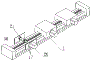
图1为本发明的结构示意图。FIG. 1 is a schematic structural diagram of the present invention.
图2为X向滑轨的内部结构示意图。Figure 2 is a schematic diagram of the internal structure of the X-direction slide rail.
图3为本发明结构的侧视图。Figure 3 is a side view of the structure of the present invention.
图4为本发明踏板倾角调节机构的内部结构示意图。FIG. 4 is a schematic diagram of the internal structure of the pedal inclination adjustment mechanism of the present invention.
图5为本发明的支撑板内部结构示意图。FIG. 5 is a schematic diagram of the internal structure of the support plate of the present invention.
图6为本发明的中央处理器示意图。FIG. 6 is a schematic diagram of the central processing unit of the present invention.
图中:1—主动X向滑轨,2—从动X向滑轨,3—X向齿条,4—X向滑块,5—X向传动丝杆,6—Y向滑块,7—踏板上臂,8—推杆电机,9—推杆,10—滑杆,11—主动齿轮,12—从动齿轮,13—U型卡扣,14—踏板下臂,15—第一双输出轴电机,16—连接杆,17—第一转轴,18—踏板,19—Y向滑轨,20—X向步进电机,21—滚动轴承,22—Y向步进电机,23—电机卡箍,24—第二双输出轴电机,25—支撑板,26—第二转轴,27—第三转轴,28—限位杆,29—U型轮,30—X向齿轮,31—倾角调节齿条,32—第四转轴,33—倾角调节齿轮,34—中央处理器。In the figure: 1—active X-direction slide rail, 2—driven X-direction slide rail, 3—X-direction rack, 4—X-direction slider, 5—X-direction drive screw, 6—Y-direction slider, 7 —Pedal upper arm, 8—Push rod motor, 9—Push rod, 10—Slide rod, 11—Driver gear, 12—Driver gear, 13—U-shaped buckle, 14—Pedal lower arm, 15—First dual output Axis motor, 16—connecting rod, 17—first shaft, 18—pedal, 19—Y-direction slide rail, 20—X-direction stepping motor, 21—rolling bearing, 22—Y-direction stepping motor, 23—motor clamp , 24—the second double output shaft motor, 25—support plate, 26—the second shaft, 27—the third shaft, 28—the limit rod, 29—the U-shaped wheel, 30—the X direction gear, 31—the inclination adjustment tooth Article, 32—the fourth shaft, 33—the inclination angle adjustment gear, 34—the central processing unit.
具体实施方式Detailed ways
一种基于腿部表面肌电信号的三踏板调节机构,包括X向滑轨、Y向滑轨以及垂直固定设置在Y向滑轨滑块上的Z向电动推杆、可发生相对转动的踏板上下臂、上下臂之间的齿轮组件、踏板倾角调节机构以及中央处理器34,中央处理器34可根据外部采集到的肌电数据进行处理分析,最终根据不同人体推荐最优的踏板配置方案。中央处理器34可满足如下方案的使用:一:驾驶员输入身高、体重等身体参数,中央处理器34可自动调节出最适合该驾驶员人体百分位的踏板位置、倾角以及踏板操纵感。二、将表面肌电传感器贴在驾驶员腿部肌肉肌腹处,采集驾驶员在驾驶车辆过程中腿部肌肉的电信号,将采集到的肌肉电信号发送到中央处理器34进行分析,优选出肌肉舒适度最高的踏板参数,中央处理器34控制电机进行调节。三、中央处理器内置调整按钮,驾驶员可自行调节踏板位置、倾角以及踏板操纵感,结构简单、操作方便。A three-pedal adjustment mechanism based on leg surface electromyographic signals, comprising an X-direction slide rail, a Y-direction slide rail, a Z-direction electric push rod vertically fixed on the Y-direction slide rail slider, and a pedal capable of relative rotation The upper and lower arms, the gear assembly between the upper and lower arms, the pedal inclination adjustment mechanism, and the
如图1和图2所示,X向滑轨包括有主动X向滑轨1和从动X向滑轨2;主动X向滑轨1包括X向齿条3、X向滑块4、X向传动丝杆5、X向步进电机20以及两端挡板,X向步进电机20固定在X向滑块4上,X向滑块4滑动连接在主动X向滑轨1上,X向滑块4包含有第一转轴17、X向齿轮30和滚动轴承21,滚动轴承21内圈与第一转轴17转动连接外圈焊接在X向滑块4上。As shown in Figures 1 and 2, the X-direction slide rail includes an active
从动X向滑轨2具有三条传动丝杆,丝杆上的滑块跟随主动X向滑轨1上的X向滑块4移动;如图3所示,X向步进电机20在中央处理器34的控制下驱动第一转轴17转动使X向滑块4沿X向传动丝杆5移动,第一转轴17两端设有滚动轴承,在第二转轴26、第三转轴27与踏板臂上臂7以及第四转轴32与踏板支撑板25接触的部位同样设有滚动轴承,后文不再赘述。The driven X-direction slide rail 2 has three drive screws, and the slider on the screw rod moves with the
Y向滑轨19固定在X向滑块4上,具有一个中间主轴和两侧传动丝杆,Y向步进电机22固定在挡板上由中央处理器34的控制,能够驱动主轴转动带动Y向滑块6沿丝杆移动。The Y-
Y向滑块6上固定设置推杆9、推杆电机8以及滑槽,推杆9通过U型卡扣13与第三转轴27转动连接。推杆电机8控制推杆9的伸缩来调节踏板的Z向位置,推杆9的上下移动促使滑杆10在滑槽内的移动。A
如图1和图3所示,踏板上下臂之间的齿轮组件包括主动齿轮11、从动齿轮12、第三转轴27、第二双输出轴电机24和电机卡箍23;第二双输出轴电机24固定在底座上与主动齿轮11连接并通过主动齿轮11将扭矩传递给从动齿轮12。当驾驶员踩下踏板时,第二双输出轴电机24输出扭矩会经过主动齿轮11传动到从动齿轮12进行减速增扭,这个力的大小可以设定,可以进行实时调节为驾驶员提供不同的踏板操纵感。As shown in Figures 1 and 3, the gear assembly between the upper and lower arms of the pedal includes a
踏板下臂14与第三转轴27固定连接,第二转轴26穿过踏板上臂7与其转动连接,第三转轴27也穿过踏板上臂7与其转动连接。The pedal
如图1和图4所示,所述的踏板倾角调节机构包括踏板18、第四转轴32、支撑板25、连接杆16、限位杆28、U型轮29、倾角调节齿轮33、倾角调节齿条31和第一双输出轴电机15;支撑板25与第四转轴32通过内部轴承转动连接;第一双输出轴电机15通过第四转轴32控制倾角调节齿轮33转动以调节踏板倾角;U型轮29固定在限位杆28之间保证与倾角调节齿轮33同轴转动;第一双输出轴电机15控制倾角调节齿轮33在倾角调节齿条31上转动可以准确实时的调节踏板的倾角,结构简单,易于实现,满足驾驶员的不同需求。As shown in FIGS. 1 and 4 , the pedal inclination adjustment mechanism includes a pedal 18 , a fourth
如图5所示,为支撑板25的内部结构示意图。保证第四转轴32的转动灵活性。As shown in FIG. 5 , it is a schematic diagram of the internal structure of the
如图6所示,为中央处理器34示意图。中央处理器34外置安装在仪表盘上控制电机运作,所述中央处理器34内置肌电信号分析算法和最优踏板配置推荐库,肌电信号分析算法可以将外部肌电信号传感器采集到的肌电信号进行特征提取,计算出驾驶员进行驾驶动作时的肌肉激活程度。肌肉激活程度的计算方法为:As shown in FIG. 6 , it is a schematic diagram of the

式中,A0为肌肉激活程度,为无量纲值,F为驾驶员进行动作时肌肉产生的电信号,Fmax为驾驶员肌肉处于最大发力状态时产生的电信号。当肌肉激活程度较低时表明驾驶员舒适度较高。中央处理器34能够通过驾驶员在不同踏板倾角、踏板感觉以及空间位置的肌肉激活程度的纵向对比分析出人体感觉最舒适的踏板布置方案。最优踏板配置推荐库内包含测得不同百分位人体舒适度最高的踏板参数,可以根据输入中央处理器的驾驶员身高、体重参数进行最优配置匹配。同时所述中央处理器34内置电机控制按钮,驾驶员可以坐在座椅上自行调节踏板倾角、感觉以及踏板的空间位置,可以充分满足驾驶员的多种驾驶需求。In the formula, A 0 is the degree of muscle activation, which is a dimensionless value, F is the electrical signal generated by the muscle when the driver performs an action, and F max is the electrical signal generated when the driver's muscle is in the state of maximum force. A lower level of muscle activation indicates higher driver comfort. The
离合踏板调节总成、制动踏板调节总成和加速踏板调节总成具有相同的调节方式。The clutch pedal adjustment assembly, brake pedal adjustment assembly and accelerator pedal adjustment assembly have the same adjustment method.
Claims (2)

Priority Applications (1)
| Application Number | Priority Date | Filing Date | Title |
|---|---|---|---|
| CN202010395635.1A CN111522393A (en) | 2020-05-12 | 2020-05-12 | A three-pedal adjustment mechanism based on leg surface EMG signals |
Applications Claiming Priority (1)
| Application Number | Priority Date | Filing Date | Title |
|---|---|---|---|
| CN202010395635.1A CN111522393A (en) | 2020-05-12 | 2020-05-12 | A three-pedal adjustment mechanism based on leg surface EMG signals |
Publications (1)
| Publication Number | Publication Date |
|---|---|
| CN111522393A true CN111522393A (en) | 2020-08-11 |
Family
ID=71907317
Family Applications (1)
| Application Number | Title | Priority Date | Filing Date |
|---|---|---|---|
| CN202010395635.1A Pending CN111522393A (en) | 2020-05-12 | 2020-05-12 | A three-pedal adjustment mechanism based on leg surface EMG signals |
Country Status (1)
| Country | Link |
|---|---|
| CN (1) | CN111522393A (en) |
Cited By (4)
| Publication number | Priority date | Publication date | Assignee | Title |
|---|---|---|---|---|
| CN113602088A (en) * | 2021-08-02 | 2021-11-05 | 岚图汽车科技有限公司 | A kind of pedal height adjustment method and adjustment device |
| KR20220063989A (en) * | 2020-11-11 | 2022-05-18 | 현대로템 주식회사 | Deadpan Foot Pedal for Railway Vehicles |
| CN115112386A (en) * | 2022-06-09 | 2022-09-27 | 合肥延锋云鹤汽车座椅有限公司 | Three-direction memory pedal plate tool |
| CN116034045A (en) * | 2020-09-04 | 2023-04-28 | 株式会社电装 | Pedal device |
Citations (10)
| Publication number | Priority date | Publication date | Assignee | Title |
|---|---|---|---|---|
| CN203376858U (en) * | 2013-07-29 | 2014-01-01 | 江苏物联网研究发展中心 | Intelligent vehicle personalization system based on NFC (near field communication) |
| CN103950383A (en) * | 2014-04-30 | 2014-07-30 | 长城汽车股份有限公司 | Automobile accelerator pedal device with adjustable pedal tread angle |
| CN104924905A (en) * | 2015-07-14 | 2015-09-23 | 吉林大学 | Automobile pedal position adjusting device considering leg muscle comfort of driver |
| CN106108896A (en) * | 2016-06-12 | 2016-11-16 | 吉林大学 | A kind of based on flesh electrometric commercial car boarding Comfort Evaluation method |
| CN107458224A (en) * | 2017-07-18 | 2017-12-12 | 吉林大学 | A kind of alarm set for preventing driver pedal maloperation |
| US20180210482A1 (en) * | 2015-08-07 | 2018-07-26 | Audi Ag | Adjustable Pedal for a Motor Vehicle |
| CN109455156A (en) * | 2018-12-18 | 2019-03-12 | 东风商用车有限公司 | Self-adaptive driving adjustment structure and method for driver of commercial vehicle |
| CN109760691A (en) * | 2019-03-18 | 2019-05-17 | 吉林大学 | It is a kind of consider electromyography signal driver comfort drive posture under the matched method of man-machine arrangement parameter |
| CN109941249A (en) * | 2019-04-22 | 2019-06-28 | 南京经纬达汽车科技有限公司 | A kind of controllable type pedal sense simulator |
| CN110562174A (en) * | 2019-08-16 | 2019-12-13 | 中国第一汽车股份有限公司 | Driving posture adjusting method and system, vehicle and storage medium |
-
2020
- 2020-05-12 CN CN202010395635.1A patent/CN111522393A/en active Pending
Patent Citations (10)
| Publication number | Priority date | Publication date | Assignee | Title |
|---|---|---|---|---|
| CN203376858U (en) * | 2013-07-29 | 2014-01-01 | 江苏物联网研究发展中心 | Intelligent vehicle personalization system based on NFC (near field communication) |
| CN103950383A (en) * | 2014-04-30 | 2014-07-30 | 长城汽车股份有限公司 | Automobile accelerator pedal device with adjustable pedal tread angle |
| CN104924905A (en) * | 2015-07-14 | 2015-09-23 | 吉林大学 | Automobile pedal position adjusting device considering leg muscle comfort of driver |
| US20180210482A1 (en) * | 2015-08-07 | 2018-07-26 | Audi Ag | Adjustable Pedal for a Motor Vehicle |
| CN106108896A (en) * | 2016-06-12 | 2016-11-16 | 吉林大学 | A kind of based on flesh electrometric commercial car boarding Comfort Evaluation method |
| CN107458224A (en) * | 2017-07-18 | 2017-12-12 | 吉林大学 | A kind of alarm set for preventing driver pedal maloperation |
| CN109455156A (en) * | 2018-12-18 | 2019-03-12 | 东风商用车有限公司 | Self-adaptive driving adjustment structure and method for driver of commercial vehicle |
| CN109760691A (en) * | 2019-03-18 | 2019-05-17 | 吉林大学 | It is a kind of consider electromyography signal driver comfort drive posture under the matched method of man-machine arrangement parameter |
| CN109941249A (en) * | 2019-04-22 | 2019-06-28 | 南京经纬达汽车科技有限公司 | A kind of controllable type pedal sense simulator |
| CN110562174A (en) * | 2019-08-16 | 2019-12-13 | 中国第一汽车股份有限公司 | Driving posture adjusting method and system, vehicle and storage medium |
Cited By (7)
| Publication number | Priority date | Publication date | Assignee | Title |
|---|---|---|---|---|
| CN116034045A (en) * | 2020-09-04 | 2023-04-28 | 株式会社电装 | Pedal device |
| KR20220063989A (en) * | 2020-11-11 | 2022-05-18 | 현대로템 주식회사 | Deadpan Foot Pedal for Railway Vehicles |
| KR102446525B1 (en) | 2020-11-11 | 2022-09-23 | 현대로템 주식회사 | Deadpan Foot Pedal for Railway Vehicles |
| CN113602088A (en) * | 2021-08-02 | 2021-11-05 | 岚图汽车科技有限公司 | A kind of pedal height adjustment method and adjustment device |
| CN113602088B (en) * | 2021-08-02 | 2023-07-18 | 岚图汽车科技有限公司 | Pedal height adjusting method and adjusting device |
| CN115112386A (en) * | 2022-06-09 | 2022-09-27 | 合肥延锋云鹤汽车座椅有限公司 | Three-direction memory pedal plate tool |
| CN115112386B (en) * | 2022-06-09 | 2023-12-22 | 合肥延锋云鹤汽车座椅有限公司 | Three-direction memory pedal tool |
Similar Documents
| Publication | Publication Date | Title |
|---|---|---|
| CN111522393A (en) | A three-pedal adjustment mechanism based on leg surface EMG signals | |
| CN104924905B (en) | A kind of automobile pedal position adjusting means for considering driver's leg muscle comfortableness | |
| CN100515325C (en) | Dynamic riding-driving circumstance human body physiological character and biomechanics testing platform | |
| CN106539666B (en) | Seat-movable lower limb exoskeleton rehabilitation training device | |
| US20090149784A1 (en) | Massage unit and massage machine of chair type having the unit | |
| CN103105302B (en) | Motorist kinematics and kinetic parameter testing system | |
| CN112168519B (en) | A multi-axis driven adaptive wheelchair | |
| CN113244578B (en) | Active mode control system of upper limb rehabilitation robot on upper plane of desktop | |
| CN112046366B (en) | Pressure sensor combined push rod mechanism for changing shape of automobile backrest | |
| Zhang et al. | Development of a tractor operator-operation environment coupled biomechanical model and analysis of lower limb muscle fatigue | |
| CN107536311B (en) | Intelligent multifunctional seat system | |
| CN202063032U (en) | Intelligent seat adjustment system of automobile | |
| CN100386604C (en) | Automobile riding position biomechanical characteristics test platform | |
| Guo et al. | Effects of operation type and handle shape of the driver controllers of high-speed train on the drivers' comfort | |
| CN112220457A (en) | A balance evaluation device | |
| CN204774668U (en) | Consider automobile pedal position control device of driver's shank muscle travelling comfort | |
| CN213758198U (en) | A balance evaluation device | |
| CN120078636A (en) | A bionic intelligent massage chair | |
| CN213723005U (en) | Multi-shaft driving self-adaptive wheelchair | |
| CN117224904B (en) | A lower limb rehabilitation training bed and its control system | |
| CN201680980U (en) | Harvester cab interface design test-bed | |
| CN219089297U (en) | Pelvic force measuring device for walking training | |
| CN112245091B (en) | Cervical vertebra rehabilitation training auxiliary robot and application method thereof | |
| CN115736834A (en) | Device and method for detecting multidimensional characteristics of soft tissues of soles | |
| CN114701432A (en) | Self-adaptive adjusting automobile stepping system and adjusting method thereof |
Legal Events
| Date | Code | Title | Description |
|---|---|---|---|
| PB01 | Publication | ||
| PB01 | Publication | ||
| SE01 | Entry into force of request for substantive examination | ||
| SE01 | Entry into force of request for substantive examination | ||
| RJ01 | Rejection of invention patent application after publication |
Application publication date: 20200811 |
|
| RJ01 | Rejection of invention patent application after publication |