CN111512425A - Temperature control for chemical mechanical polishing - Google Patents
Temperature control for chemical mechanical polishing Download PDFInfo
- Publication number
- CN111512425A CN111512425A CN201980006568.5A CN201980006568A CN111512425A CN 111512425 A CN111512425 A CN 111512425A CN 201980006568 A CN201980006568 A CN 201980006568A CN 111512425 A CN111512425 A CN 111512425A
- Authority
- CN
- China
- Prior art keywords
- polishing
- polishing pad
- temperature
- thermal control
- platen
- Prior art date
- Legal status (The legal status is an assumption and is not a legal conclusion. Google has not performed a legal analysis and makes no representation as to the accuracy of the status listed.)
- Granted
Links
Images


Classifications
-
- B—PERFORMING OPERATIONS; TRANSPORTING
- B24—GRINDING; POLISHING
- B24B—MACHINES, DEVICES, OR PROCESSES FOR GRINDING OR POLISHING; DRESSING OR CONDITIONING OF ABRADING SURFACES; FEEDING OF GRINDING, POLISHING, OR LAPPING AGENTS
- B24B37/00—Lapping machines or devices; Accessories
- B24B37/005—Control means for lapping machines or devices
- B24B37/015—Temperature control
-
- B—PERFORMING OPERATIONS; TRANSPORTING
- B24—GRINDING; POLISHING
- B24B—MACHINES, DEVICES, OR PROCESSES FOR GRINDING OR POLISHING; DRESSING OR CONDITIONING OF ABRADING SURFACES; FEEDING OF GRINDING, POLISHING, OR LAPPING AGENTS
- B24B37/00—Lapping machines or devices; Accessories
- B24B37/04—Lapping machines or devices; Accessories designed for working plane surfaces
- B24B37/07—Lapping machines or devices; Accessories designed for working plane surfaces characterised by the movement of the work or lapping tool
- B24B37/10—Lapping machines or devices; Accessories designed for working plane surfaces characterised by the movement of the work or lapping tool for single side lapping
- B24B37/102—Lapping machines or devices; Accessories designed for working plane surfaces characterised by the movement of the work or lapping tool for single side lapping the workpieces or work carriers being able to rotate freely due to a frictional contact with the lapping tool
-
- B—PERFORMING OPERATIONS; TRANSPORTING
- B24—GRINDING; POLISHING
- B24B—MACHINES, DEVICES, OR PROCESSES FOR GRINDING OR POLISHING; DRESSING OR CONDITIONING OF ABRADING SURFACES; FEEDING OF GRINDING, POLISHING, OR LAPPING AGENTS
- B24B37/00—Lapping machines or devices; Accessories
- B24B37/11—Lapping tools
- B24B37/20—Lapping pads for working plane surfaces
-
- B—PERFORMING OPERATIONS; TRANSPORTING
- B24—GRINDING; POLISHING
- B24B—MACHINES, DEVICES, OR PROCESSES FOR GRINDING OR POLISHING; DRESSING OR CONDITIONING OF ABRADING SURFACES; FEEDING OF GRINDING, POLISHING, OR LAPPING AGENTS
- B24B37/00—Lapping machines or devices; Accessories
- B24B37/27—Work carriers
- B24B37/30—Work carriers for single side lapping of plane surfaces
-
- B—PERFORMING OPERATIONS; TRANSPORTING
- B24—GRINDING; POLISHING
- B24B—MACHINES, DEVICES, OR PROCESSES FOR GRINDING OR POLISHING; DRESSING OR CONDITIONING OF ABRADING SURFACES; FEEDING OF GRINDING, POLISHING, OR LAPPING AGENTS
- B24B55/00—Safety devices for grinding or polishing machines; Accessories fitted to grinding or polishing machines for keeping tools or parts of the machine in good working condition
- B24B55/02—Equipment for cooling the grinding surfaces, e.g. devices for feeding coolant
-
- B—PERFORMING OPERATIONS; TRANSPORTING
- B24—GRINDING; POLISHING
- B24B—MACHINES, DEVICES, OR PROCESSES FOR GRINDING OR POLISHING; DRESSING OR CONDITIONING OF ABRADING SURFACES; FEEDING OF GRINDING, POLISHING, OR LAPPING AGENTS
- B24B57/00—Devices for feeding, applying, grading or recovering grinding, polishing or lapping agents
- B24B57/02—Devices for feeding, applying, grading or recovering grinding, polishing or lapping agents for feeding of fluid, sprayed, pulverised, or liquefied grinding, polishing or lapping agents
-
- G—PHYSICS
- G05—CONTROLLING; REGULATING
- G05D—SYSTEMS FOR CONTROLLING OR REGULATING NON-ELECTRIC VARIABLES
- G05D23/00—Control of temperature
- G05D23/19—Control of temperature characterised by the use of electric means
- G05D23/20—Control of temperature characterised by the use of electric means with sensing elements having variation of electric or magnetic properties with change of temperature
- G05D23/24—Control of temperature characterised by the use of electric means with sensing elements having variation of electric or magnetic properties with change of temperature the sensing element having a resistance varying with temperature, e.g. a thermistor
- G05D23/2401—Control of temperature characterised by the use of electric means with sensing elements having variation of electric or magnetic properties with change of temperature the sensing element having a resistance varying with temperature, e.g. a thermistor using a heating element as a sensing element
-
- H—ELECTRICITY
- H10—SEMICONDUCTOR DEVICES; ELECTRIC SOLID-STATE DEVICES NOT OTHERWISE PROVIDED FOR
- H10P—GENERIC PROCESSES OR APPARATUS FOR THE MANUFACTURE OR TREATMENT OF DEVICES COVERED BY CLASS H10
- H10P52/00—Grinding, lapping or polishing of wafers, substrates or parts of devices
-
- H—ELECTRICITY
- H10—SEMICONDUCTOR DEVICES; ELECTRIC SOLID-STATE DEVICES NOT OTHERWISE PROVIDED FOR
- H10P—GENERIC PROCESSES OR APPARATUS FOR THE MANUFACTURE OR TREATMENT OF DEVICES COVERED BY CLASS H10
- H10P72/00—Handling or holding of wafers, substrates or devices during manufacture or treatment thereof
- H10P72/04—Apparatus for manufacture or treatment
- H10P72/0428—Apparatus for mechanical treatment or grinding or cutting
-
- H—ELECTRICITY
- H10—SEMICONDUCTOR DEVICES; ELECTRIC SOLID-STATE DEVICES NOT OTHERWISE PROVIDED FOR
- H10P—GENERIC PROCESSES OR APPARATUS FOR THE MANUFACTURE OR TREATMENT OF DEVICES COVERED BY CLASS H10
- H10P72/00—Handling or holding of wafers, substrates or devices during manufacture or treatment thereof
- H10P72/04—Apparatus for manufacture or treatment
- H10P72/0431—Apparatus for thermal treatment
-
- H—ELECTRICITY
- H10—SEMICONDUCTOR DEVICES; ELECTRIC SOLID-STATE DEVICES NOT OTHERWISE PROVIDED FOR
- H10P—GENERIC PROCESSES OR APPARATUS FOR THE MANUFACTURE OR TREATMENT OF DEVICES COVERED BY CLASS H10
- H10P72/00—Handling or holding of wafers, substrates or devices during manufacture or treatment thereof
- H10P72/06—Apparatus for monitoring, sorting, marking, testing or measuring
- H10P72/0602—Temperature monitoring
-
- H—ELECTRICITY
- H10—SEMICONDUCTOR DEVICES; ELECTRIC SOLID-STATE DEVICES NOT OTHERWISE PROVIDED FOR
- H10P—GENERIC PROCESSES OR APPARATUS FOR THE MANUFACTURE OR TREATMENT OF DEVICES COVERED BY CLASS H10
- H10P72/00—Handling or holding of wafers, substrates or devices during manufacture or treatment thereof
- H10P72/06—Apparatus for monitoring, sorting, marking, testing or measuring
- H10P72/0612—Production flow monitoring, e.g. for increasing throughput
Landscapes
- Engineering & Computer Science (AREA)
- Mechanical Engineering (AREA)
- Automation & Control Theory (AREA)
- Physics & Mathematics (AREA)
- General Physics & Mathematics (AREA)
- Finish Polishing, Edge Sharpening, And Grinding By Specific Grinding Devices (AREA)
- Mechanical Treatment Of Semiconductor (AREA)
- Constituent Portions Of Griding Lathes, Driving, Sensing And Control (AREA)
- Grinding-Machine Dressing And Accessory Apparatuses (AREA)
Abstract
一种化学机械抛光设备包括压板、载体、分配器和温度控制系统,压板保持抛光垫,载体在抛光工艺期间保持基板抵靠抛光垫的抛光表面,分配器向抛光表面供应抛光液,温度控制系统包含主体,所述主体经配置以接触抛光表面或抛光表面上的抛光液。主体支撑定位在抛光垫上的热控制模块。

A chemical mechanical polishing apparatus includes a platen, a carrier, a dispenser, and a temperature control system. The platen holds a polishing pad. The carrier holds a substrate against a polishing surface of the polishing pad during a polishing process. The dispenser supplies a polishing liquid to the polishing surface. The temperature control system includes a body configured to contact the polishing surface or the polishing liquid on the polishing surface. The body supports a thermal control module positioned above the polishing pad.
Description
技术领域technical field
本公开文本关于化学机械抛光(CMP),且更具体地关于化学机械抛光期间的温度控制。This disclosure relates to chemical mechanical polishing (CMP), and more particularly to temperature control during chemical mechanical polishing.
背景技术Background technique
通常通过在半导体晶片上依序沉积导电层、半导体层或绝缘层而在基板上形成集成电路。各种制造工艺需要对基板上的层作平坦化。例如,一个制造步骤包括在非平坦表面上沉积填料层并使该填料层平坦化。对于某些应用,填料层被平坦化,直到暴露出图案化层的顶表面。例如,可以在图案化的绝缘层上沉积金属层以填充绝缘层中的沟槽和孔。在平坦化之后,图案化层的孔与沟槽中的金属的剩余部分形成通孔、插塞和线,以在基板上的薄膜电路之间提供导电路径。作为另一示例,可以在图案化的导电层上沉积介电层,并接着对所述介电层平坦化以允许进行后续的光刻步骤。Integrated circuits are typically formed on substrates by sequentially depositing conductive, semiconducting, or insulating layers on a semiconductor wafer. Various manufacturing processes require planarization of layers on the substrate. For example, one fabrication step includes depositing and planarizing a filler layer on a non-planar surface. For some applications, the filler layer is planarized until the top surface of the patterned layer is exposed. For example, a metal layer can be deposited over the patterned insulating layer to fill trenches and holes in the insulating layer. After planarization, the holes in the patterned layer form vias, plugs and lines with the remainder of the metal in the trenches to provide conductive paths between thin film circuits on the substrate. As another example, a dielectric layer may be deposited over the patterned conductive layer and then planarized to allow subsequent photolithography steps.
化学机械抛光(CMP)是一种已接受的平坦化方法。此平坦化方法通常需要将基板安装在承载头上。通常将基板的暴露表面抵靠旋转的抛光垫放置。承载头在基板上提供可控制的负载以抵靠着抛光垫推动所述负载。通常将具有研磨颗粒的抛光浆料供应到抛光垫的表面。Chemical Mechanical Polishing (CMP) is an accepted method of planarization. This planarization method typically requires the substrate to be mounted on the carrier head. The exposed surface of the substrate is typically placed against a rotating polishing pad. The carrier head provides a controllable load on the substrate to push the load against the polishing pad. A polishing slurry with abrasive particles is typically supplied to the surface of the polishing pad.
发明内容SUMMARY OF THE INVENTION
在一个方面中,一种化学机械抛光设备包括压板、载体和温度控制系统,所述压板保持抛光垫,所述载体在抛光工艺期间保持基板抵靠抛光垫的抛光表面。所述温度控制系统包括多个热控制模块,所述多个热控制模块在多个不同的径向位置处定位在抛光垫上方。所述多个热控制模块中的每个热控制模块经配置以独立地加热或冷却抛光垫的径向区域。In one aspect, a chemical mechanical polishing apparatus includes a platen that holds a polishing pad, a carrier, and a temperature control system, the carrier holding a substrate against a polishing surface of the polishing pad during a polishing process. The temperature control system includes a plurality of thermal control modules positioned over the polishing pad at a plurality of different radial positions. Each thermal control module of the plurality of thermal control modules is configured to independently heat or cool radial regions of the polishing pad.
在另一方面中,一种化学机械抛光设备包括压板、载体、温度控制系统和第一致动器,所述压板保持抛光垫,所述载体在抛光工艺期间保持基板抵靠抛光垫的抛光表面,所述温度控制系统包括主体,所述主体包含定位在抛光垫上方的热控制模块,所述第一致动器调整主体相对于抛光垫的垂直位置。In another aspect, a chemical mechanical polishing apparatus includes a platen holding a polishing pad, a carrier, a temperature control system, and a first actuator, the carrier holding a substrate against a polishing surface of the polishing pad during a polishing process , the temperature control system includes a body including a thermal control module positioned above the polishing pad, the first actuator adjusting the vertical position of the body relative to the polishing pad.
在另一方面中,一种化学机械抛光设备包括压板、载体、分配器和温度控制系统,所述压板保持抛光垫,所述载体在抛光工艺期间保持基板抵靠抛光垫的抛光表面,所述分配器将抛光液供应到抛光表面,所述温度控制系统包含主体,所述主体经配置以接触抛光表面或抛光表面上的抛光液。主体支撑定位在抛光垫上方的热控制模块。In another aspect, a chemical mechanical polishing apparatus includes a platen holding a polishing pad, a carrier, a dispenser, and a temperature control system, the carrier holding a substrate against a polishing surface of the polishing pad during a polishing process, the The dispenser supplies the polishing fluid to the polishing surface, and the temperature control system includes a body configured to contact the polishing surface or the polishing fluid on the polishing surface. The body supports a thermal control module positioned over the polishing pad.
任何上述方面的实施可包括以下特征中的一个或多个。Implementations of any of the above aspects may include one or more of the following features.
每个热控制模块可以包括以下各者中的一个或多个:红外光源、热电热泵、热交换器、电阻加热器和流体分配器。一个或多个温度传感器可在多个不同的径向位置处测量抛光表面的多个温度测量值。控制器可经配置以接收多个温度测量值并控制多个热控制模块以使抛光垫的温度分布更接近期望的温度分布。Each thermal control module may include one or more of the following: an infrared light source, a thermoelectric heat pump, a heat exchanger, a resistive heater, and a fluid distributor. One or more temperature sensors may measure multiple temperature measurements of the polishing surface at multiple different radial locations. The controller may be configured to receive the plurality of temperature measurements and control the plurality of thermal control modules to bring the temperature profile of the polishing pad closer to the desired temperature profile.
基座可定位在压板的一侧,且主体可在抛光垫上从基座侧向延伸。第二致动器可使主体侧向扫过抛光垫。The pedestal can be positioned on one side of the platen, and the body can extend laterally from the pedestal on the polishing pad. The second actuator may cause the body to sweep laterally across the polishing pad.
主体的一层可定位于热控制模块和主体之间。热控制模块可直接接触抛光垫或抛光液。与抛光垫或抛光液接触的主体的至少一部分可以是陶瓷。与抛光垫或抛光液接触的主体的至少一部分可包括碳化硅、氮化硅或氮化铝。A layer of the body may be positioned between the thermal control module and the body. The thermal control module can directly contact the polishing pad or polishing liquid. At least a portion of the body in contact with the polishing pad or slurry may be ceramic. At least a portion of the body in contact with the polishing pad or slurry may include silicon carbide, silicon nitride, or aluminum nitride.
致动器可调整主体相对于抛光垫的垂直位置。主体的底表面可接触抛光表面。主体的底表面接触抛光表面上的抛光液。热控制模块可包括具有热电热泵和热交换器的堆叠。热交换器可在热电热泵上方。The actuator adjusts the vertical position of the body relative to the polishing pad. The bottom surface of the body may contact the polished surface. The bottom surface of the body contacts the polishing liquid on the polishing surface. The thermal control module may include a stack with a thermoelectric heat pump and a heat exchanger. The heat exchanger may be above the thermoelectric heat pump.
控制器可经配置以控制到热电热泵的电流,以使热泵将热驱动到抛光垫或从抛光垫驱动热,且控制器控制通过热交换器的流体的温度或流速,使热交换器升高或降低热电热泵的顶表面的温度。The controller can be configured to control the current to the thermoelectric heat pump so that the heat pump drives heat to or from the polishing pad, and the controller controls the temperature or flow rate of the fluid through the heat exchanger, causing the heat exchanger to increase Or lower the temperature of the top surface of the thermoelectric heat pump.
实施可包括以下优点中的一个或多个。可以减小抛光操作的温度变化。这可以改善抛光工艺抛光可预测性。可以减小从一个抛光操作到另一个抛光操作的温度变化。这可以改善晶片到晶片的均匀性并改善抛光工艺的可重复性。可以减小基板上的温度变化。这可以改善晶片内均匀性。Implementations may include one or more of the following advantages. The temperature variation of the polishing operation can be reduced. This can improve the polishing predictability of the polishing process. Temperature variations from one polishing operation to another may be reduced. This can improve wafer-to-wafer uniformity and improve repeatability of the polishing process. Temperature variations on the substrate can be reduced. This can improve intra-wafer uniformity.
在附图和以下说明中描述一个或多个实施的细节。从说明书和附图以及权利要求书,其他方面、特征和优点将变得明显。The details of one or more implementations are set forth in the accompanying drawings and the description below. Other aspects, features and advantages will become apparent from the description and drawings, and from the claims.
附图说明Description of drawings
图1示出抛光设备的示例的示意性横截面图。Figure 1 shows a schematic cross-sectional view of an example of a polishing apparatus.
图2示出示例性化学机械抛光设备的示意性顶视图。2 shows a schematic top view of an exemplary chemical mechanical polishing apparatus.
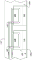
图3示出具有多个温度控制模块的温度控制系统的一部分的示意性横截面图。3 shows a schematic cross-sectional view of a portion of a temperature control system having a plurality of temperature control modules.
图4示出用于温度控制系统的热交换器的示意图。Figure 4 shows a schematic diagram of a heat exchanger for a temperature control system.
图5示出另一示例性化学机械抛光设备的示意性顶视图。5 shows a schematic top view of another exemplary chemical mechanical polishing apparatus.
具体实施方式Detailed ways
化学机械抛光通过在基板、抛光液和抛光垫之间的介面处的机械磨蚀和化学蚀刻的组合来操作。在抛光工艺期间,由于基板的表面和抛光垫之间的摩擦而产生大量的热。此外,一些工艺还包括原位垫调节步骤,在原位垫调节步骤中将调节盘(如,涂有研磨钻石颗粒的盘)压抵住旋转的抛光垫以调节和纹理化抛光垫表面。调节工艺的磨蚀也能产生热。例如,在典型的一分钟铜CMP工艺中,标称下压力为2psi、去除速率为
CMP工艺中的化学相关变量(如,作为参与反应的引发(initiation)和速率)和机械相关变量(如,抛光垫的表面摩擦系数和粘弹性)都是强烈依赖于温度的。因此,抛光垫的表面温度的变化导致去除速率、抛光均匀性、侵蚀、凹陷和残留物的变化。通过在抛光期间更严格地控制抛光垫表面的温度,可以减小温度的变化,且可以改善如晶片内不均匀性或晶片到晶片的不均匀性所测量的抛光性能。Both chemically related variables (eg, initiation and rate as participating reactions) and mechanically related variables (eg, surface friction coefficient and viscoelasticity of the polishing pad) in the CMP process are strongly temperature dependent. Thus, changes in the surface temperature of the polishing pad result in changes in removal rate, polishing uniformity, erosion, dishing, and residue. By more tightly controlling the temperature of the polishing pad surface during polishing, temperature variations can be reduced and polishing performance as measured by intra-wafer non-uniformity or wafer-to-wafer non-uniformity can be improved.
已经提出了一些用于温度控制的技术。作为一个示例,冷却剂可以穿过压板。作为另一个示例,可以控制输送到抛光垫的抛光液的温度。但是,这些技术可能不够。例如,压板必须通过抛光垫本身的主体供应或吸取热量以控制抛光表面的温度。抛光垫通常是塑料材料和不良导热体,使得压板的热控制可能很困难。另一方面,抛光液可能不具有显著的热质量。Several techniques have been proposed for temperature control. As one example, the coolant may pass through the platen. As another example, the temperature of the polishing fluid delivered to the polishing pad can be controlled. However, these techniques may not be enough. For example, the platen must supply or draw heat through the body of the polishing pad itself to control the temperature of the polishing surface. Polishing pads are often plastic materials and poor thermal conductors, making thermal control of the platen can be difficult. On the other hand, slurries may not have significant thermal mass.
可解决这些问题的一个技术是将温度受控的主体与抛光垫的抛光表面直接接触,或者将温度受控的主体与抛光垫上的抛光液直接接触。这个主体的温度可以在其长度上变化,从而提供对抛光垫温度的径向控制。One technique that can address these problems is to place a temperature-controlled body in direct contact with the polishing surface of the polishing pad, or a temperature-controlled body in direct contact with the polishing liquid on the polishing pad. The temperature of this body can vary over its length, thereby providing radial control of the polishing pad temperature.
另外一个问题是在CMP工艺期间沿着旋转的抛光垫的半径的温度升高经常是不均匀的。不受任何特定理论的限制,抛光头和垫调节器的不同扫描剖面有时可以在抛光垫的每个径向区域中具有不同的驻留时间。此外,抛光垫和抛光头和/或垫调节器之间的相对线性速度也沿着抛光垫的半径变化。这些效应可导致抛光垫表面上的不均匀发热,这可导致晶片内去除速率变化。Another problem is that the temperature rise during the CMP process is often non-uniform along the radius of the rotating polishing pad. Without being bound by any particular theory, different scan profiles of the polishing head and pad conditioner can sometimes have different dwell times in each radial region of the polishing pad. In addition, the relative linear velocity between the polishing pad and the polishing head and/or pad conditioner also varies along the radius of the polishing pad. These effects can lead to uneven heating across the surface of the polishing pad, which can lead to variations in removal rates within the wafer.
可解决这些问题的一个技术是具有沿着抛光垫的半径分隔开的多个温度控制模块。每个温度控制模块包含位于抛光垫上方的热传递元件,且热传递元件可以包括冷却元件或加热元件或这两者。每个温度控制模块可以独立地提供选择量的冷却或加热到旋转的抛光垫上的相应径向区域,该相应径向区域在每个模块下方行进。以这种方式,可以控制抛光垫表面上的每个径向区域的温度,这允许降低温度不均匀性。One technique that can address these issues is to have multiple temperature control modules spaced along the radius of the polishing pad. Each temperature control module includes a heat transfer element located above the polishing pad, and the heat transfer element may include a cooling element or a heating element or both. Each temperature control module can independently provide a selected amount of cooling or heating to a corresponding radial area on the rotating polishing pad that runs beneath each module. In this way, the temperature of each radial region on the polishing pad surface can be controlled, which allows for reduced temperature non-uniformity.
图1和图2示出化学机械抛光系统的抛光站20的示例。抛光站20包括可旋转的盘形压板24,抛光垫30位于盘形压板24上。压板24可操作以绕轴25旋转。例如,马达22可以转动驱动轴28以使压板24旋转。抛光垫30可以是双层抛光垫,其具有外抛光层34和较软的背托层32。1 and 2 illustrate an example of a polishing
抛光站20可以包括供应口或组合式供应-冲洗臂39,以将抛光液38(诸如研磨浆料)分配到抛光垫30上。抛光站20可以包括垫调节器设备90,垫调节器设备90具有调节盘92(参见图2)以保持抛光垫30的表面粗糙度。调节盘90可以定位在臂94的端部,臂94可以摆动,以使盘90径向地扫过抛光垫30。The polishing
承载头70可操作以保持基板10抵靠抛光垫30。承载头70自支撑结构72(如,旋转料架(carousel)或轨道)悬挂,且承载头70通过驱动轴74连接到承载头旋转马达76,使得承载头可绕轴71旋转。可选地,承载头70可以侧向振动,如,在旋转料架上的滑块上,通过沿着轨道的运动,或通过旋转料架本身的旋转振荡侧向振动。The
承载头70可以包括保持环84,以保持基板。在一些实施中,保持环84可包括高导电性部分,如,承载环可以包括薄的下塑料部分86与厚的上导电部分88,薄的下塑料部分86接触抛光垫。在一些实施中,高导电性部分是金属,例如,与正被抛光的层相同的金属,如铜。The
在操作中,压板绕其中心轴25旋转,且承载头绕其中心轴71旋转并侧向地平移越过抛光垫30的顶表面。在存在多个承载头的情况下,每个承载头70可以独立控制其抛光参数,例如每个承载头可以独立地控制施加到每个个别基板的压力。In operation, the platen rotates about its
承载头70可以包括柔性膜80及多个可加压的腔室82,柔性膜80具有与基板10的背面接触的基板安装表面,多个可加压的腔室82将不同的压力施加到基板10上的不同区域,如不同的径向区域。承载头也可以包括保持环84,以保持基板。The
在一些实施中,抛光站20包括温度传感器64,以监测抛光站或抛光站中的部件中的温度,如抛光垫和/或抛光垫上的浆料的温度。例如,温度传感器64可以是红外(IR)传感器(如IR相机),其位于抛光垫30上方且经配置以测量抛光垫30和/或抛光垫上的浆料38的温度。具体地,温度传感器64可以经配置以测量沿着抛光垫30的半径的多个点处的温度,以产生径向温度分布。例如,IR相机可以具有跨越抛光垫30的半径的视场。In some implementations, the polishing
在一些实施中,温度传感器是接触传感器,而不是非接触传感器。例如,温度传感器64可以是位于压板24上或压板24中的热电偶或IR温度计。另外,温度传感器64可以与抛光垫直接接触。In some implementations, the temperature sensor is a contact sensor rather than a contactless sensor. For example,
在一些实施中,多个温度传感器可以在抛光垫30上的不同径向位置处间隔开,以提供沿着抛光垫30的半径的多个点处的温度。此技术可以用于IR相机的替代或附加。In some implementations, multiple temperature sensors may be spaced apart at different radial locations on polishing
尽管在图1中示出为为了监测抛光垫30和/或垫30上的浆料38的温度而定位,但温度传感器64可以定位在承载头70内,以测量基板10的温度。温度传感器64可以与基板10的半导体晶片直接接触(即,接触传感器)。在一些实施中,多个温度传感器包括于抛光站22中,如,以测量抛光站或抛光站中的不同部件的温度。Although shown in FIG. 1 as being positioned for monitoring the temperature of polishing
抛光系统20还包括温度控制系统100,以控制抛光垫30和/或抛光垫上的浆料38的温度。温度控制系统100包括至少一个细长主体110,细长主体110在抛光垫30上从抛光垫的边缘延伸到抛光垫30的中心处或中心附近(如,在抛光垫的总半径的5%内)。例如,主体110可以是由基座112支撑的臂,以在抛光垫30上延伸。基座112可以被支撑在与压板24相同的框架40上。主体110经定位以避免与其他硬体部件(诸如抛光头70、垫调节盘90和浆料分配臂39)碰撞。The polishing
主体110可以是大致线性的且可以沿其长度具有基本均匀的宽度,虽然其他形状(诸如圆扇形(也称为“派形切片”)、弧形或三角形楔形(均作为系统的俯视图))可以用于实现主体110和抛光垫表面之间所需的热传递区域。具体而言,多个热控制模块可以由楔形臂支撑,该楔形臂在远离轴的一端较宽。例如,图5示出作为楔形的温度控制系统100的主体110(为简单起见,图1中未示出抛光设备的其他元件)。The
回到图1和图2,主体110可以与抛光垫30直接接触。或者,主体可以与抛光垫30稍微分开,仍然与抛光垫30的表面上的一层抛光液(如浆料)接触。在一些实施(如,非接触式加热器,诸如IR灯)中,主体悬挂在抛光垫30上方而不接触抛光垫或抛光液。基座112可以包括致动器(如,线性致动器)以升高或降低主体110。Returning to FIGS. 1 and 2 , the
主体110的侧向位置可以是固定的,或者可以由另一个致动器控制。例如,主体110可以由基座112中的马达驱动,以侧向扫过抛光垫。例如,可以驱动主体110以执行扫掠(sweep)运动以避免与其他硬体部件碰撞且/或增加抛光垫表面上的有效热传递区域。The lateral position of the
主体110可以包括排成一线的多个温度控制模块120。例如,热控制模块120可以沿着压板的半径定位,如,沿着抛光垫的径向方向间隔开。每个温度控制模块120包含热传递元件,热传递元件可以包括冷却元件或加热元件或这两者。当抛光垫在模块下面旋转时,每个温度控制模块120可以独立地向抛光垫上的相应径向区域提供选择量的冷却或加热。The
由于沿着抛光垫30的径向方向分隔开,温度控制模块对沿着抛光垫30的径向方向间隔开的区域施加加热或冷却。As spaced apart in the radial direction of the
区域的尺寸和形状取决于热控制模块120中的加热或冷却元件(如电阻加热器、冷却剂的通道等)的放置。The size and shape of the zones depend on the placement of heating or cooling elements (eg, resistive heaters, passages for coolant, etc.) in the
区域可以是矩形的,如图2所示,或者可以是一些其他形状,诸如梯形(见图5)、卵形、弧形、多边形或更复杂的形状。The area may be rectangular, as shown in Figure 2, or may be some other shape, such as a trapezoid (see Figure 5), an oval, an arc, a polygon, or more complex shapes.
此外,区域可以是相同的尺寸和/或形状,如图2所示,但这不是必需的。一些区域的尺寸可以与其他区域不同。例如,外部区域可以大于内部区域(内部和外部相对于压板的旋转轴进行划分)。也就是说,离轴较远的区域可以大于更靠近轴的区域。因此,离轴较远的区域可以具有比更靠近轴的区域更宽的角展度。具体地,从压板的旋转轴向外移动,每个后继的(successive)区域可以大于先前的区域(如图5所示)。Additionally, the regions may be the same size and/or shape as shown in Figure 2, but this is not required. Some regions can be of different dimensions than others. For example, the outer area may be larger than the inner area (inner and outer are divided with respect to the axis of rotation of the platen). That is, regions further from the axis may be larger than regions closer to the axis. Thus, regions further from the axis may have a wider angular spread than regions closer to the axis. Specifically, moving outward from the axis of rotation of the platen, each successive area may be larger than the previous area (as shown in Figure 5).
温度控制模块120的部件可以包含于主体110内,使得主体110本身用于在抛光垫和/或浆料与温度控制模块120之间热传导热量。主体110的底表面的材料可以由高导热率材料形成,该高导热率材料也耐受抛光垫的磨损。主体110的材料应该与抛光工艺在化学上相容且对抛光液具有高耐化学性。例如,至少主体110的底部可以是陶瓷材料,诸如碳化硅、氮化硅或氮化铝。整个主体110可以由该材料形成,或者陶瓷材料可以涂覆在另一种材料(如铝)的主体上。可选地,导热材料可以涂覆有薄CVD钻石涂层(类似于钻石或无定形类钻石碳DLC涂层)以具有更好的耐磨性。涂层可以减少垫的磨损,提高对抛光液的耐化学性,且具有更高的导热性。The components of the
或者,温度控制模块120的部件可以固定于主体110并悬挂在主体110下面,使得所述这些部件与抛光垫和/或浆料直接接触。在这种情况下,主体110不需要用于在抛光垫和/或浆料与温度控制模块120之间热传导热量。Alternatively, components of the
对于冷却元件,温度控制模块120可以包括具有热电(TE)冷却元件的冷板式冷却器。冷却元件也可以是低温热交换器,其通过再循环低温流体或气体(即,低于抛光垫和/或抛光液的温度)来操作。冷却元件还可包括分配器,该分配器经配置以将低温气体或液体或固体输送到抛光垫30的表面上。例如,冷却元件可以是经配置以产生低温气体或液体喷流的喷嘴。低温气体、液体或固体也可以在抛光垫表面上经受吸热相变。另外,冷却元件可以使用上述技术的组合。例如,可以通过在热电冷却元件的顶部堆迭低温热交换器来形成冷却元件,以进一步提高冷却能力。For cooling elements, the
对于加热元件,温度控制模块120可以包括热板式加热器,其内部具有热电(TE)加热元件或电阻加热元件。加热元件也可以是高温热交换器,其通过再循环高温流体或气体(即,高于抛光垫和/或抛光液的温度)来操作。加热元件还可包括分配器,该分配器经配置以将高温气体或液体或固体输送到抛光垫30的表面上。例如,加热元件可以是经配置以产生高温气体或液体喷流的喷嘴。高温气体或液体或固体也可以在抛光垫表面上经受放热相变。加热元件也可以以热辐射源的形式,如红外(IR)灯或低强度激光。另外,加热元件可以使用上述技术的组合。例如,可以通过在热电加热元件的顶部堆迭高温交换器来形成加热元件,以进一步提高加热能力。For heating elements, the
抛光系统20还可包括控制器90以控制各种部件的操作,如温度控制系统100。控制器90经配置以从温度传感器64接收针对抛光垫的每个径向区域的温度测量值。控制器90可以将测量的温度分布与期望的温度分布比较,且为每个温度控制模块产生到控制机构(如致动器、电源、泵、阀等)的反馈信号。由控制器90例如基于内反馈算法计算反馈信号,以使控制机构通过温度控制模块的冷却或加热元件调整冷却或加热的量,使得抛光垫和/或浆料达到(或至少更趋近)所期望的温度分布。The polishing
控制技术的示例包括使电源供应调整红外光源的强度,使电源供应调整流过热电加热器或冷却器的电流量,使致动器移动热控制模块更靠近或更远离抛光垫,使泵增加或减少热交换器中的流速,以及使阀调整流过热交换器的热或冷流体的比例。Examples of control techniques include having the power supply adjust the intensity of the infrared light source, having the power supply adjust the amount of current flowing through the thermoelectric heater or cooler, having the actuator move the thermal control module closer or further away from the polishing pad, having the pump increase or The flow rate in the heat exchanger is reduced, and the valve is made to adjust the proportion of hot or cold fluid flowing through the heat exchanger.
用于(作为冷却元件的)TE冷却元件和低温热交换器的堆迭或(作为加热元件的)TE加热元件和高温热交换器的堆迭的控制机构的示例可以包括:(I)控制供应给TE元件的电流(或电压)的量;(II)在脉冲宽度调制下控制TE元件在开和关模式下的相对百分比,(III)在双极调制下控制TE元件在冷却和加热模式下的相对百分比;(IV)控制在低温或高温热交换器内再循环的液体的温度或流速。Examples of control mechanisms for stacks of TE cooling elements and low temperature heat exchangers (as cooling elements) or stacks of TE heating elements and high temperature heat exchangers (as heating elements) may include: (1) Controlling supply The amount of current (or voltage) to the TE element; (II) control the relative percentage of the TE element in on and off mode under pulse width modulation, (III) control the TE element in cooling and heating mode under bipolar modulation (IV) Control the temperature or flow rate of the liquid recirculated in the low temperature or high temperature heat exchanger.
用于电阻加热器元件的控制机构的示例可以包括(I)控制提供给电阻加热器的电流(或电压)的量,以及(II)在脉冲宽度调制下控制电阻加热器在开和关模式下的相对百分比。Examples of control mechanisms for resistive heater elements may include (I) controlling the amount of current (or voltage) supplied to the resistive heater, and (II) controlling the resistive heater in on and off modes under pulse width modulation relative percentage.
在一些实施中,温度控制模块120可以提供双向温度控制。因此,每个模块120可以根据不同的处理要求提供选择性加热和选择性冷却。In some implementations, the
在一些实施中,通过在每个温度控制模块120中包括冷却元件和加热元件两者来提供双向温度控制。作为示例,参考图3,每个热控制模块120可以具有热传递元件,该热传递元件包括热电或电阻加热元件130和热交换器140的堆迭。通过每个热交换器的流速可以由阀142控制。热交换器140可用作冷却元件,例如通过使低温流体流过热交换器。热电或电阻加热元件130可用作加热元件,例如通过使电流流过元件130。取决于在抛光期间每个阶段是否需要冷却或加热,可以在不同时间接合加热元件和冷却元件。In some implementations, bidirectional temperature control is provided by including both cooling elements and heating elements in each
然而,在一些实施中,在每个温度控制模块120中仅需要一个热传递元件。例如,热电元件130或热交换器140可以用作加热或冷却元件,例如取决于电流流动的方向或流过热交换器的流体的温度。However, in some implementations, only one heat transfer element is required in each
在一些实施中,每个热控制模块120包括热电或电阻加热元件130和热交换器140的堆迭,其中热电加热元件130和热交换器140都经配置用于双向温度控制。温度控制模块120可以通过以下方式用作冷却元件:(i)选择热电元件130的电流流动方向以使热从抛光垫被泵送出及(ii)在热交换器140内使低温流体循环。相同的温度控制模块120可以通过以下方式用作加热元件:(i)切换热电元件130内的电流流动方向(反转极性)以使热被泵送入垫中及(ii)在热交换器140内从循环低温流体切换成高温流体。In some implementations, each
例如,参考图4,两个流体循环器C1和C2可以在两个不同的温度下供应流体。例如,C1可以泵送冷水,而C2可以泵送热水。使用阀V1和V2,热流体或冷流体可以流到温度控制模块120a和120b。示例性流体包括水和/或乙二醇。流体可以同时或在不同时间点流动。此流体用于冷却或加热热电模块130的非接触侧。For example, referring to Figure 4, two fluid circulators C1 and C2 may supply fluid at two different temperatures. For example, C1 can pump cold water, while C2 can pump hot water. Using valves VI and V2, hot or cold fluid can flow to
回到图2,在一些实施中,抛光系统20包括多个温度控制系统100a、100b,每个温度控制系统具有其自己的主体110,主体110具有热控制模块120的阵列122。浆料分配臂39可以定位在热控制模块的两个阵列122之间。Returning to FIG. 2 , in some implementations, polishing
温度控制系统中的一个温度控制系统的主体(如沿着旋转方向相对于承载头70处于前导位置的主体110(如图2中的系统110b的主体110))可以用作去除浆料的阻挡层。例如,系统100b的主体110可以经定位比系统100a的主体110更靠近抛光垫30。在操作中,抛光液可以由浆料输送臂39分配,由下面的垫承载且由温度控制系统110a的热控制模块120的阵列122加热,且随后在承载头70下面承载以与基板对接。接着,使用过的浆料可以从承载头70承载且被温度控制系统110b的主体110偏转,以转移到垫区域之外。温度控制系统110a的主体110也可以经定位在抛光垫30上径向涂抹抛光液。The body of one of the temperature control systems (eg, the
在一些实施中,温度控制系统100可以使用两阶段加热/冷却。热泵可以用作第一阶段,而热交换器可以用作第二阶段。第一阶段更靠近抛光垫。In some implementations, the
热电元件性能的设计规范是冷侧和热侧之间的差异。该差异有局限性。例如,假设使用热电元件来加热目标表面。热电元件的底表面将是热侧(且应该比目标更热)且顶表面将是冷侧。目标将靠近底部热侧放置。从底部热侧到目标发生热传递。The design specification for thermoelectric element performance is the difference between the cold side and the hot side. This difference is limited. For example, suppose a thermoelectric element is used to heat the target surface. The bottom surface of the thermoelectric element will be the hot side (and should be hotter than the target) and the top surface will be the cold side. The target will be placed close to the bottom hot side. Heat transfer occurs from the bottom hot side to the target.
大部分热电元件在顶侧和底侧之间保持设定的温差。然而,加热热电元件的顶侧允许底侧变得更热,这可导致从底部到目标的热传递有更高效率。例如,热电元件的顶侧可以通过在其上流动热液体来实现。通过使用与热交换器(如水循环器)串联的热电元件的这种两阶段冷却现象在CMP中会是有利的。这也适用于反向冷却现象。Most thermoelectric elements maintain a set temperature difference between the top and bottom sides. However, heating the top side of the thermoelectric element allows the bottom side to become hotter, which can result in more efficient heat transfer from the bottom to the target. For example, the top side of the thermoelectric element can be achieved by flowing a hot liquid over it. This two-stage cooling phenomenon by using a thermoelectric element in series with a heat exchanger such as a water circulator can be advantageous in CMP. This also applies to the reverse cooling phenomenon.
水不能用作超过摄氏0度的冷却剂。水和乙二醇的混合物优选低于摄氏0度,但经常由于乙二醇而导致热传递的折衷。Water cannot be used as a coolant above 0 degrees Celsius. The mixture of water and ethylene glycol is preferably below 0 degrees Celsius, but often results in compromises in heat transfer due to ethylene glycol.
沿着垫的径向方向的热电元件的多个堆迭(其中具有累积或单独的流体入口和出口),将使得沿着CMP垫对温度进行区域控制。Multiple stacks of thermoelectric elements (with cumulative or separate fluid inlets and outlets) along the radial direction of the pad will allow for regional control of temperature along the CMP pad.
在一些实施中,主体110还用作浆料擦拭器或散布器。例如,参考图2,抛光液可以从臂39分配。由于压板24的旋转,浆料将在抛光垫30上被承载朝向温度控制系统100a。具体地,假设主体110经定位以接触抛光垫30,后(trailing)表面(与旋转方向相反的表面)的底边缘将用作抑制浆料从臂39流动的阻挡层。如此一来,确实在主体110下面通过(如在抛光垫30中的凹槽中或通过主体110和抛光垫30之间的间隙)的浆料将更均匀地分布。In some implementations, the
可能的优点包括以下所述。Possible advantages include the following.
(I)所述设备基本上是专用的、独用的硬件,以在CMP工艺期间控制抛光垫的表面温度。(1) The apparatus is essentially dedicated, stand-alone hardware to control the surface temperature of the polishing pad during the CMP process.
(II)所述设备不依赖于通过调整CMP处理参数(诸如抛光头或垫调节器盘的向下力)来控制垫表面温度。如此一来,此温度控制设备对现有CMP工艺的影响较小。(II) The apparatus does not rely on controlling the pad surface temperature by adjusting CMP process parameters such as the downward force of the polishing head or pad conditioner disk. As such, the temperature control device has less impact on the existing CMP process.
(III)通过热控制模块中的元件的某些选择,例如,当使用如上所述的热电元件和热交换器的堆迭时,例如相比于用于冷却目的的空气涡流或去离子水喷流,所述温度控制设备对抛光垫表面的干扰较小。(III) By some selection of elements in the thermal control module, eg when using a stack of thermoelectric elements and heat exchangers as described above, eg compared to air vortex or deionized water spray for cooling purposes flow, the temperature control device interferes less with the polishing pad surface.
(IV)通过对热控制模块中的元件的某些选择,例如,当使用如上所述的热电元件和热交换器的堆迭时,所述温度控制设备可以实现包括在相同的热控制模块中冷却和加热的双向温度控制。因此,在实施期间,新设备的占地面积可以很小。此外,双向温度控制使得新的处理旋钮能够在整个CMP工艺的不同阶段进行调整,以达到产量、拓朴(topography)、残留物、腐蚀等所测量的改善的CMP结果。(IV) With certain selection of elements in a thermal control module, for example, when using a stack of thermoelectric elements and heat exchangers as described above, the temperature control device can be achieved to be included in the same thermal control module Bidirectional temperature control for cooling and heating. Therefore, during implementation, the footprint of the new device can be small. Additionally, bi-directional temperature control enables new processing knobs to be adjusted at various stages throughout the CMP process to achieve improved CMP results as measured by yield, topography, residue, corrosion, and more.
(V)使用模块阵列中的多个温度控制模块可以减小CMP工艺期间的焊盘内温度不均匀性。此外,通过热控制模块中的元件的某些选择,例如,当使用如上所述的热电元件和热交换器的堆迭时,存在多级控制机制以在每个个别模块中提供更可靠的温度控制,以达到每个径向区域的所需温度或温度变化率并降低抛光垫表面上的温度不均匀性。(V) The use of multiple temperature control modules in the module array can reduce intra-pad temperature non-uniformity during the CMP process. Furthermore, with certain selection of elements in the thermal control module, for example, when using the stack of thermoelectric elements and heat exchangers as described above, there is a multi-level control mechanism to provide more reliable temperatures in each individual module Control to achieve the desired temperature or rate of temperature change for each radial zone and reduce temperature non-uniformity across the pad surface.
上述抛光设备和方法可以应用于各种抛光系统中。抛光垫或承载头之一或两者可以移动以提供抛光表面和基板之间的相对运动。例如,压板可以绕轨道运动而不是旋转。抛光垫可以是固定于压板的圆形(或一些其他形状)垫。端点检测系统的一些方面可适用于线性抛光系统,例如,其中抛光垫是线性移动的连续或盘式(reel-to-reel)带。抛光层可以是标准(例如,具有填料或不具有填料的聚氨酯)抛光材料、软材料或固定研磨材料。相对定位的术语用于指系统或基板内的相对定位;应该理解的是,在抛光操作期间,抛光表面和基板可以保持在垂直定向或一些其他定向上。The polishing apparatus and method described above can be applied to various polishing systems. Either or both of the polishing pad or the carrier head can be moved to provide relative motion between the polishing surface and the substrate. For example, the platen may orbit rather than rotate. The polishing pad may be a circular (or some other shaped) pad secured to the platen. Some aspects of the endpoint detection system are applicable to linear polishing systems, eg, where the polishing pad is a linearly moving continuous or reel-to-reel belt. The polishing layer can be a standard (eg, filled or unfilled polyurethane) polishing material, a soft material, or a fixed abrasive material. The term relative positioning is used to refer to relative positioning within a system or substrate; it should be understood that the polishing surface and substrate may remain in a vertical orientation or some other orientation during a polishing operation.
控制器90的功能操作可以使用一个或多个计算机程序产品来实现,即,有形地体现在非暂态计算机可读存储介质中的一个或多个计算机程序,用于由数据处理设备(如可编程处理器、计算机、或多个处理器或计算机)执行或控制数据处理设备的操作。The functional operations of
已经描述了本发明的许多实施例。然而,应该理解,在不背离本发明的精神和范围的情况下,可进行各种修改。因此,其他实施例在以下权利要求书的范围内。A number of embodiments of the present invention have been described. It should be understood, however, that various modifications may be made without departing from the spirit and scope of the present invention. Accordingly, other embodiments are within the scope of the following claims.
Claims (16)
Priority Applications (1)
| Application Number | Priority Date | Filing Date | Title |
|---|---|---|---|
| CN202510728957.6A CN120307185A (en) | 2018-06-27 | 2019-06-21 | Temperature Control of Chemical Mechanical Polishing |
Applications Claiming Priority (5)
| Application Number | Priority Date | Filing Date | Title |
|---|---|---|---|
| US201862690876P | 2018-06-27 | 2018-06-27 | |
| US62/690,876 | 2018-06-27 | ||
| US201862778201P | 2018-12-11 | 2018-12-11 | |
| US62/778,201 | 2018-12-11 | ||
| PCT/US2019/038411 WO2020005749A1 (en) | 2018-06-27 | 2019-06-21 | Temperature control of chemical mechanical polishing |
Related Child Applications (1)
| Application Number | Title | Priority Date | Filing Date |
|---|---|---|---|
| CN202510728957.6A Division CN120307185A (en) | 2018-06-27 | 2019-06-21 | Temperature Control of Chemical Mechanical Polishing |
Publications (2)
| Publication Number | Publication Date |
|---|---|
| CN111512425A true CN111512425A (en) | 2020-08-07 |
| CN111512425B CN111512425B (en) | 2025-05-30 |
Family
ID=68985157
Family Applications (2)
| Application Number | Title | Priority Date | Filing Date |
|---|---|---|---|
| CN202510728957.6A Pending CN120307185A (en) | 2018-06-27 | 2019-06-21 | Temperature Control of Chemical Mechanical Polishing |
| CN201980006568.5A Active CN111512425B (en) | 2018-06-27 | 2019-06-21 | Temperature Control of Chemical Mechanical Polishing |
Family Applications Before (1)
| Application Number | Title | Priority Date | Filing Date |
|---|---|---|---|
| CN202510728957.6A Pending CN120307185A (en) | 2018-06-27 | 2019-06-21 | Temperature Control of Chemical Mechanical Polishing |
Country Status (6)
| Country | Link |
|---|---|
| US (3) | US11597052B2 (en) |
| JP (3) | JP7287987B2 (en) |
| KR (2) | KR20250004341A (en) |
| CN (2) | CN120307185A (en) |
| TW (2) | TW202402454A (en) |
| WO (1) | WO2020005749A1 (en) |
Cited By (6)
| Publication number | Priority date | Publication date | Assignee | Title |
|---|---|---|---|---|
| CN112405333A (en) * | 2020-12-04 | 2021-02-26 | 华海清科(北京)科技有限公司 | Chemical mechanical polishing device and polishing method |
| CN113070812A (en) * | 2021-05-08 | 2021-07-06 | 清华大学 | Polishing solution conveying device capable of adjusting temperature and chemical mechanical polishing equipment |
| CN113442068A (en) * | 2021-05-08 | 2021-09-28 | 华海清科(北京)科技有限公司 | Polishing solution conveying device and chemical mechanical polishing equipment |
| CN113442058A (en) * | 2021-05-08 | 2021-09-28 | 华海清科股份有限公司 | Polishing solution conveying device and chemical mechanical polishing equipment |
| CN113732936A (en) * | 2021-05-08 | 2021-12-03 | 清华大学 | Polishing temperature control device, chemical mechanical polishing system and method |
| CN116237866A (en) * | 2023-03-31 | 2023-06-09 | 江苏科技大学 | A grinding and polishing machine capable of real-time temperature control and its temperature control method |
Families Citing this family (21)
| Publication number | Priority date | Publication date | Assignee | Title |
|---|---|---|---|---|
| JP6161999B2 (en) * | 2013-08-27 | 2017-07-12 | 株式会社荏原製作所 | Polishing method and polishing apparatus |
| JP6923342B2 (en) * | 2017-04-11 | 2021-08-18 | 株式会社荏原製作所 | Polishing equipment and polishing method |
| JP7287987B2 (en) | 2018-06-27 | 2023-06-06 | アプライド マテリアルズ インコーポレイテッド | Temperature control for chemical mechanical polishing |
| TWI838459B (en) | 2019-02-20 | 2024-04-11 | 美商應用材料股份有限公司 | Chemical mechanical polishing apparatus and method of chemical mechanical polishing |
| TWI859239B (en) | 2019-05-29 | 2024-10-21 | 美商應用材料股份有限公司 | Apparatus and method for steam treatment stations for chemical mechanical polishing system |
| US11628478B2 (en) | 2019-05-29 | 2023-04-18 | Applied Materials, Inc. | Steam cleaning of CMP components |
| US11633833B2 (en) | 2019-05-29 | 2023-04-25 | Applied Materials, Inc. | Use of steam for pre-heating of CMP components |
| TWI872101B (en) | 2019-08-13 | 2025-02-11 | 美商應用材料股份有限公司 | Apparatus and method for cmp temperature control |
| US11897079B2 (en) | 2019-08-13 | 2024-02-13 | Applied Materials, Inc. | Low-temperature metal CMP for minimizing dishing and corrosion, and improving pad asperity |
| KR102835295B1 (en) * | 2020-03-06 | 2025-07-18 | 가부시키가이샤 에바라 세이사꾸쇼 | Polishing apparatus, treatment system, and polishing method |
| CN115103738A (en) * | 2020-06-29 | 2022-09-23 | 应用材料公司 | Temperature and slurry flow rate control in CMP |
| KR102905650B1 (en) | 2020-06-29 | 2025-12-30 | 어플라이드 머티어리얼스, 인코포레이티드 | Control of steam generation for chemical mechanical polishing |
| US11577358B2 (en) * | 2020-06-30 | 2023-02-14 | Applied Materials, Inc. | Gas entrainment during jetting of fluid for temperature control in chemical mechanical polishing |
| KR20250004369A (en) | 2020-06-30 | 2025-01-07 | 어플라이드 머티어리얼스, 인코포레이티드 | Apparatus and method for cmp temperature control |
| EP4182119A4 (en) * | 2020-07-14 | 2024-08-07 | Applied Materials, Inc. | Methods of detecting non-conforming substrate processing events during chemical mechanical polishing |
| JP7710876B2 (en) * | 2021-04-19 | 2025-07-22 | 株式会社荏原製作所 | Polishing method and polishing apparatus |
| JP7663468B2 (en) * | 2021-04-28 | 2025-04-16 | 株式会社荏原製作所 | Polishing apparatus and polishing method |
| CN114406834B (en) * | 2021-12-08 | 2023-09-15 | 华亚东营塑胶有限公司 | Plastic grinding device for plastic product processing |
| JP7781683B2 (en) | 2022-03-09 | 2025-12-08 | キオクシア株式会社 | Semiconductor manufacturing equipment and semiconductor device manufacturing method |
| JP2024016938A (en) * | 2022-07-27 | 2024-02-08 | 株式会社荏原製作所 | polishing equipment |
| US20250114909A1 (en) * | 2023-10-05 | 2025-04-10 | Applied Materials, Inc. | Cold liquid polishing control |
Citations (7)
| Publication number | Priority date | Publication date | Assignee | Title |
|---|---|---|---|---|
| CN1537038A (en) * | 2001-12-26 | 2004-10-13 | ��ķ�о�����˾ | Apparatus and method for controlling wafer temperature in chemical mechanical polishing |
| US20100015894A1 (en) * | 2008-07-17 | 2010-01-21 | Ming-Che Ho | CMP by Controlling Polish Temperature |
| US20100203806A1 (en) * | 2009-02-09 | 2010-08-12 | Kabushiki Kaisha Toshiba | Semiconductor manufacturing apparatus |
| CN102179757A (en) * | 2009-12-28 | 2011-09-14 | 株式会社荏原制作所 | Substrate polishing apparatus, substrate polishing method, and apparatus for adjusting polishing surface temperature of polishing pad in the polishing apparatus |
| US20130210173A1 (en) * | 2012-02-14 | 2013-08-15 | Taiwan Semiconductor Manufacturing Co., Ltd. | Multiple Zone Temperature Control for CMP |
| CN205465663U (en) * | 2015-12-18 | 2016-08-17 | K.C.科技股份有限公司 | Chemical mechanical grinding device |
| CN107097145A (en) * | 2016-02-22 | 2017-08-29 | 株式会社荏原制作所 | The apparatus and method being adjusted for the surface temperature to grinding pad |
Family Cites Families (123)
| Publication number | Priority date | Publication date | Assignee | Title |
|---|---|---|---|---|
| US4450652A (en) | 1981-09-04 | 1984-05-29 | Monsanto Company | Temperature control for wafer polishing |
| ATE106300T1 (en) | 1989-04-01 | 1994-06-15 | Messer Griesheim Gmbh | POLISHING OR GRINDING EQUIPMENT. |
| US4919232A (en) | 1989-05-12 | 1990-04-24 | Hugh Lofton | Cold lubricant misting device and method |
| US5196353A (en) | 1992-01-03 | 1993-03-23 | Micron Technology, Inc. | Method for controlling a semiconductor (CMP) process by measuring a surface temperature and developing a thermal image of the wafer |
| US5700180A (en) | 1993-08-25 | 1997-12-23 | Micron Technology, Inc. | System for real-time control of semiconductor wafer polishing |
| US5478435A (en) | 1994-12-16 | 1995-12-26 | National Semiconductor Corp. | Point of use slurry dispensing system |
| JP3633062B2 (en) | 1994-12-22 | 2005-03-30 | 株式会社デンソー | Polishing method and polishing apparatus |
| US5722875A (en) | 1995-05-30 | 1998-03-03 | Tokyo Electron Limited | Method and apparatus for polishing |
| US5597442A (en) | 1995-10-16 | 1997-01-28 | Taiwan Semiconductor Manufacturing Company Ltd. | Chemical/mechanical planarization (CMP) endpoint method using measurement of polishing pad temperature |
| US5738574A (en) | 1995-10-27 | 1998-04-14 | Applied Materials, Inc. | Continuous processing system for chemical mechanical polishing |
| US5709593A (en) | 1995-10-27 | 1998-01-20 | Applied Materials, Inc. | Apparatus and method for distribution of slurry in a chemical mechanical polishing system |
| US5762544A (en) | 1995-10-27 | 1998-06-09 | Applied Materials, Inc. | Carrier head design for a chemical mechanical polishing apparatus |
| US5643050A (en) | 1996-05-23 | 1997-07-01 | Industrial Technology Research Institute | Chemical/mechanical polish (CMP) thickness monitor |
| JP3672685B2 (en) * | 1996-11-29 | 2005-07-20 | 松下電器産業株式会社 | Polishing method and polishing apparatus |
| US5873769A (en) | 1997-05-30 | 1999-02-23 | Industrial Technology Research Institute | Temperature compensated chemical mechanical polishing to achieve uniform removal rates |
| US5893753A (en) | 1997-06-05 | 1999-04-13 | Texas Instruments Incorporated | Vibrating polishing pad conditioning system and method |
| US5868003A (en) | 1997-07-14 | 1999-02-09 | Praxair Technology, Inc. | Apparatus for producing fine snow particles from a flow liquid carbon dioxide |
| US5765394A (en) | 1997-07-14 | 1998-06-16 | Praxair Technology, Inc. | System and method for cooling which employs charged carbon dioxide snow |
| JPH1133897A (en) | 1997-07-24 | 1999-02-09 | Matsushita Electron Corp | Chemical-mechanical polishing method and device |
| DE19737849A1 (en) | 1997-08-29 | 1999-03-11 | Siemens Ag | Device and method for heating a liquid or viscous polishing agent and device for polishing wafers |
| DE19748020A1 (en) | 1997-10-30 | 1999-05-06 | Wacker Siltronic Halbleitermat | Method and device for polishing semiconductor wafers |
| US5957750A (en) | 1997-12-18 | 1999-09-28 | Micron Technology, Inc. | Method and apparatus for controlling a temperature of a polishing pad used in planarizing substrates |
| US6121144A (en) | 1997-12-29 | 2000-09-19 | Intel Corporation | Low temperature chemical mechanical polishing of dielectric materials |
| US6000997A (en) | 1998-07-10 | 1999-12-14 | Aplex, Inc. | Temperature regulation in a CMP process |
| US6023941A (en) | 1998-07-22 | 2000-02-15 | Praxair Technology, Inc. | Horizontal carbon dioxide snow horn with adjustment for desired snow |
| US6280289B1 (en) | 1998-11-02 | 2001-08-28 | Applied Materials, Inc. | Method and apparatus for detecting an end-point in chemical mechanical polishing of metal layers |
| US6159073A (en) | 1998-11-02 | 2000-12-12 | Applied Materials, Inc. | Method and apparatus for measuring substrate layer thickness during chemical mechanical polishing |
| US6319098B1 (en) | 1998-11-13 | 2001-11-20 | Applied Materials, Inc. | Method of post CMP defect stability improvement |
| US6422927B1 (en) | 1998-12-30 | 2002-07-23 | Applied Materials, Inc. | Carrier head with controllable pressure and loading area for chemical mechanical polishing |
| US6224461B1 (en) | 1999-03-29 | 2001-05-01 | Lam Research Corporation | Method and apparatus for stabilizing the process temperature during chemical mechanical polishing |
| US6315635B1 (en) | 1999-03-31 | 2001-11-13 | Taiwan Semiconductor Manufacturing Company, Ltd | Method and apparatus for slurry temperature control in a polishing process |
| US6151913A (en) | 1999-04-23 | 2000-11-28 | Praxair Technology, Inc. | Method and apparatus for agglomerating fine snow particles |
| US6225224B1 (en) | 1999-05-19 | 2001-05-01 | Infineon Technologies Norht America Corp. | System for dispensing polishing liquid during chemical mechanical polishing of a semiconductor wafer |
| US6776692B1 (en) | 1999-07-09 | 2004-08-17 | Applied Materials Inc. | Closed-loop control of wafer polishing in a chemical mechanical polishing system |
| JP2001060725A (en) | 1999-08-23 | 2001-03-06 | Komatsu Ltd | Temperature adjustment plate |
| US6399501B2 (en) | 1999-12-13 | 2002-06-04 | Applied Materials, Inc. | Method and apparatus for detecting polishing endpoint with optical monitoring |
| US6640151B1 (en) | 1999-12-22 | 2003-10-28 | Applied Materials, Inc. | Multi-tool control system, method and medium |
| US6461980B1 (en) | 2000-01-28 | 2002-10-08 | Applied Materials, Inc. | Apparatus and process for controlling the temperature of a substrate in a plasma reactor chamber |
| US6257954B1 (en) | 2000-02-23 | 2001-07-10 | Memc Electronic Materials, Inc. | Apparatus and process for high temperature wafer edge polishing |
| US6647309B1 (en) | 2000-05-22 | 2003-11-11 | Advanced Micro Devices, Inc. | Method and apparatus for automated generation of test semiconductor wafers |
| US20020023715A1 (en) | 2000-05-26 | 2002-02-28 | Norio Kimura | Substrate polishing apparatus and substrate polishing mehod |
| US20010055940A1 (en) | 2000-06-15 | 2001-12-27 | Leland Swanson | Control of CMP removal rate uniformity by selective control of slurry temperature |
| US20020039874A1 (en) | 2000-08-17 | 2002-04-04 | Hecker Philip E. | Temperature endpointing of chemical mechanical polishing |
| KR100470137B1 (en) | 2000-08-23 | 2005-02-04 | 주식회사 에프에스티 | Polishing apparatus comprising frozen pad and method for polishing using the same |
| US6679769B2 (en) | 2000-09-19 | 2004-01-20 | Rodel Holdings, Inc | Polishing pad having an advantageous micro-texture and methods relating thereto |
| US6946394B2 (en) | 2000-09-20 | 2005-09-20 | Kla-Tencor Technologies | Methods and systems for determining a characteristic of a layer formed on a specimen by a deposition process |
| US6494765B2 (en) | 2000-09-25 | 2002-12-17 | Center For Tribology, Inc. | Method and apparatus for controlled polishing |
| JP3544521B2 (en) | 2000-11-28 | 2004-07-21 | 日本圧着端子製造株式会社 | Modular jack |
| JP2002170792A (en) | 2000-11-29 | 2002-06-14 | Mitsubishi Electric Corp | Polishing liquid supply apparatus and polishing liquid supply method, polishing apparatus and polishing method, and method of manufacturing semiconductor device |
| US20020068454A1 (en) | 2000-12-01 | 2002-06-06 | Applied Materials, Inc. | Method and composition for the removal of residual materials during substrate planarization |
| US6503131B1 (en) | 2001-08-16 | 2003-01-07 | Applied Materials, Inc. | Integrated platen assembly for a chemical mechanical planarization system |
| US6562185B2 (en) | 2001-09-18 | 2003-05-13 | Advanced Micro Devices, Inc. | Wafer based temperature sensors for characterizing chemical mechanical polishing processes |
| US6543251B1 (en) | 2001-10-17 | 2003-04-08 | Praxair Technology, Inc. | Device and process for generating carbon dioxide snow |
| JP3627182B2 (en) | 2001-12-28 | 2005-03-09 | 株式会社半導体先端テクノロジーズ | CMP apparatus, polishing pad and polishing method |
| US6896586B2 (en) | 2002-03-29 | 2005-05-24 | Lam Research Corporation | Method and apparatus for heating polishing pad |
| US6764388B2 (en) | 2002-05-09 | 2004-07-20 | Taiwan Semiconductor Manufacturing Co., Ltd | High-pressure pad cleaning system |
| JP2004042217A (en) | 2002-07-12 | 2004-02-12 | Ebara Corp | Polishing method, polishing apparatus and polishing tool manufacturing method |
| DE10252613A1 (en) | 2002-11-12 | 2004-05-27 | Infineon Technologies Ag | Method, device, computer-readable storage medium and computer program element for monitoring a manufacturing process |
| JP2004202666A (en) | 2002-12-26 | 2004-07-22 | Sony Corp | Polishing apparatus, polishing member, and polishing method |
| JP4448297B2 (en) * | 2002-12-27 | 2010-04-07 | 株式会社荏原製作所 | Substrate polishing apparatus and substrate polishing method |
| US7008295B2 (en) | 2003-02-04 | 2006-03-07 | Applied Materials Inc. | Substrate monitoring during chemical mechanical polishing |
| JP2004306173A (en) | 2003-04-03 | 2004-11-04 | Sharp Corp | Substrate polishing machine |
| US7040966B2 (en) | 2003-04-16 | 2006-05-09 | Applied Materials | Carbonation of pH controlled KOH solution for improved polishing of oxide films on semiconductor wafers |
| US7112960B2 (en) | 2003-07-31 | 2006-09-26 | Applied Materials, Inc. | Eddy current system for in-situ profile measurement |
| US6908370B1 (en) | 2003-12-04 | 2005-06-21 | Intel Corporation | Rinse apparatus and method for wafer polisher |
| JP2005203522A (en) | 2004-01-14 | 2005-07-28 | Nikon Corp | Exposure method and apparatus, and device manufacturing method |
| US7255771B2 (en) | 2004-03-26 | 2007-08-14 | Applied Materials, Inc. | Multiple zone carrier head with flexible membrane |
| JP2005311246A (en) | 2004-04-26 | 2005-11-04 | Tokyo Seimitsu Co Ltd | Chemical mechanical polishing apparatus and method |
| US20070205112A1 (en) | 2004-08-27 | 2007-09-06 | Masako Kodera | Polishing apparatus and polishing method |
| JP4290158B2 (en) | 2004-12-20 | 2009-07-01 | 三洋電機株式会社 | Semiconductor device |
| KR20060076332A (en) | 2004-12-29 | 2006-07-04 | 삼성전자주식회사 | Chemical mechanical polishing apparatus |
| JP2007035973A (en) | 2005-07-27 | 2007-02-08 | Fujitsu Ltd | Semiconductor device manufacturing method and polishing apparatus |
| US7201634B1 (en) | 2005-11-14 | 2007-04-10 | Infineon Technologies Ag | Polishing methods and apparatus |
| JP4787063B2 (en) | 2005-12-09 | 2011-10-05 | 株式会社荏原製作所 | Polishing apparatus and polishing method |
| US20070227901A1 (en) * | 2006-03-30 | 2007-10-04 | Applied Materials, Inc. | Temperature control for ECMP process |
| US8192257B2 (en) | 2006-04-06 | 2012-06-05 | Micron Technology, Inc. | Method of manufacture of constant groove depth pads |
| DE602006007960D1 (en) | 2006-05-18 | 2009-09-03 | Air Liquide | Use of a mixture of liquid nitrogen and carbon dioxide foam for freezing |
| DE102006056623A1 (en) * | 2006-11-30 | 2008-06-05 | Advanced Micro Devices, Inc., Sunnyvale | System for chemical mechanical polishing, has controllable movable foreman head, which is formed to mount substrate and to hold in position, and foreman cushion, is mounted on plate, which is coupled with drive arrangement |
| CN101500721B (en) | 2007-05-11 | 2011-10-05 | 新日本制铁株式会社 | Controlled cooling method of steel plate |
| JP4902433B2 (en) * | 2007-06-13 | 2012-03-21 | 株式会社荏原製作所 | Polishing surface heating and cooling device for polishing equipment |
| US8257142B2 (en) | 2008-04-15 | 2012-09-04 | Rohm And Haas Electronic Materials Cmp Holdings, Inc. | Chemical mechanical polishing method |
| KR20090046468A (en) | 2007-11-06 | 2009-05-11 | 주식회사 동부하이텍 | Conditioning of chemical mechanical polishing equipment |
| US8439723B2 (en) | 2008-08-11 | 2013-05-14 | Applied Materials, Inc. | Chemical mechanical polisher with heater and method |
| US8292691B2 (en) | 2008-09-29 | 2012-10-23 | Applied Materials, Inc. | Use of pad conditioning in temperature controlled CMP |
| KR20100101379A (en) | 2009-03-09 | 2010-09-17 | 삼성전자주식회사 | Method of chemical mechanical polishing phase-change materials and method of fabricating phase-change random access memory using the same method |
| US20100279435A1 (en) | 2009-04-30 | 2010-11-04 | Applied Materials, Inc. | Temperature control of chemical mechanical polishing |
| JP5481417B2 (en) | 2010-08-04 | 2014-04-23 | 株式会社東芝 | Manufacturing method of semiconductor device |
| US8591286B2 (en) * | 2010-08-11 | 2013-11-26 | Applied Materials, Inc. | Apparatus and method for temperature control during polishing |
| JP2012148376A (en) | 2011-01-20 | 2012-08-09 | Ebara Corp | Polishing method and polishing apparatus |
| JP5628067B2 (en) * | 2011-02-25 | 2014-11-19 | 株式会社荏原製作所 | Polishing apparatus provided with temperature adjustment mechanism of polishing pad |
| JP5695963B2 (en) * | 2011-04-28 | 2015-04-08 | 株式会社荏原製作所 | Polishing method |
| CN102419603A (en) | 2011-05-26 | 2012-04-18 | 上海华力微电子有限公司 | Temperature control system of polishing pad in chemical mechanical polishing process |
| TWI548483B (en) | 2011-07-19 | 2016-09-11 | 荏原製作所股份有限公司 | Grinding device and method |
| JP5791987B2 (en) * | 2011-07-19 | 2015-10-07 | 株式会社荏原製作所 | Polishing apparatus and method |
| JP2013042066A (en) | 2011-08-19 | 2013-02-28 | Toshiba Corp | Method of manufacturing semiconductor device |
| JP2013099814A (en) | 2011-11-08 | 2013-05-23 | Toshiba Corp | Polishing method and polishing apparatus |
| US9005999B2 (en) | 2012-06-30 | 2015-04-14 | Applied Materials, Inc. | Temperature control of chemical mechanical polishing |
| JP2014130881A (en) | 2012-12-28 | 2014-07-10 | Ebara Corp | Polishing device |
| WO2014113220A1 (en) | 2013-01-15 | 2014-07-24 | Applied Materials, Inc | Cryogenic liquid cleaning apparatus and methods |
| US20140251952A1 (en) * | 2013-03-08 | 2014-09-11 | Applied Materials, Inc. | Surface modified polishing pad |
| JP6030980B2 (en) | 2013-03-26 | 2016-11-24 | 株式会社荏原製作所 | Polishing apparatus temperature control system and polishing apparatus |
| US9630295B2 (en) | 2013-07-17 | 2017-04-25 | Taiwan Semiconductor Manufacturing Co., Ltd. | Mechanisms for removing debris from polishing pad |
| JP6161999B2 (en) * | 2013-08-27 | 2017-07-12 | 株式会社荏原製作所 | Polishing method and polishing apparatus |
| JP2015104769A (en) | 2013-11-29 | 2015-06-08 | 株式会社荏原製作所 | Polishing table and polishing device |
| JP6139420B2 (en) | 2014-01-10 | 2017-05-31 | 株式会社東芝 | Polishing apparatus and polishing method |
| US9636797B2 (en) | 2014-02-12 | 2017-05-02 | Applied Materials, Inc. | Adjusting eddy current measurements |
| US9539699B2 (en) | 2014-08-28 | 2017-01-10 | Ebara Corporation | Polishing method |
| US10058975B2 (en) * | 2016-02-12 | 2018-08-28 | Applied Materials, Inc. | In-situ temperature control during chemical mechanical polishing with a condensed gas |
| KR101722555B1 (en) * | 2016-03-08 | 2017-04-03 | 주식회사 케이씨텍 | Chemical mechanical polishing apparatus and method |
| KR101816694B1 (en) | 2016-07-26 | 2018-01-11 | 주식회사 케이씨텍 | Chemical mechanical polishing apparatus and control method thereof |
| JP6752657B2 (en) * | 2016-08-23 | 2020-09-09 | 株式会社荏原製作所 | Polishing method and polishing equipment |
| JP6782628B2 (en) | 2016-12-21 | 2020-11-11 | 東京エレクトロン株式会社 | Substrate processing equipment, substrate processing system and substrate processing method |
| JP2018122406A (en) | 2017-02-02 | 2018-08-09 | 株式会社荏原製作所 | Heat exchanger for adjusting surface temperature of polishing pad, polishing device, polishing method and recording medium in which computer program is recorded |
| US11103970B2 (en) | 2017-08-15 | 2021-08-31 | Taiwan Semiconductor Manufacturing Co, , Ltd. | Chemical-mechanical planarization system |
| KR102591901B1 (en) | 2017-10-31 | 2023-10-20 | 가부시키가이샤 에바라 세이사꾸쇼 | Heat exchanger for regulating temperature of polishing surface of polishing pad, polishing apparatus having such heat exchanger, polishing method for substrate using such heat exchanger, and computer-readable storage medium storing a program for regulating temperature of polishing surface of polishing pad |
| TWI825043B (en) | 2017-11-14 | 2023-12-11 | 美商應用材料股份有限公司 | Method and system for temperature control of chemical mechanical polishing |
| JP7287987B2 (en) | 2018-06-27 | 2023-06-06 | アプライド マテリアルズ インコーポレイテッド | Temperature control for chemical mechanical polishing |
| US10807213B2 (en) | 2018-06-29 | 2020-10-20 | Taiwan Semiconductor Manufacturing Co., Ltd. | Chemical mechanical polishing apparatus and method |
| KR20200056015A (en) | 2018-11-14 | 2020-05-22 | 부산대학교 산학협력단 | Cmp apparatus and method of multi-zone temperature profile control |
| TWI838459B (en) | 2019-02-20 | 2024-04-11 | 美商應用材料股份有限公司 | Chemical mechanical polishing apparatus and method of chemical mechanical polishing |
| TWI872101B (en) | 2019-08-13 | 2025-02-11 | 美商應用材料股份有限公司 | Apparatus and method for cmp temperature control |
| US11897079B2 (en) | 2019-08-13 | 2024-02-13 | Applied Materials, Inc. | Low-temperature metal CMP for minimizing dishing and corrosion, and improving pad asperity |
| US20210046603A1 (en) | 2019-08-13 | 2021-02-18 | Applied Materials, Inc. | Slurry temperature control by mixing at dispensing |
-
2019
- 2019-06-21 JP JP2020571596A patent/JP7287987B2/en active Active
- 2019-06-21 CN CN202510728957.6A patent/CN120307185A/en active Pending
- 2019-06-21 CN CN201980006568.5A patent/CN111512425B/en active Active
- 2019-06-21 WO PCT/US2019/038411 patent/WO2020005749A1/en not_active Ceased
- 2019-06-21 TW TW112136423A patent/TW202402454A/en unknown
- 2019-06-21 KR KR1020247039502A patent/KR20250004341A/en active Pending
- 2019-06-21 US US16/448,980 patent/US11597052B2/en active Active
- 2019-06-21 KR KR1020217002783A patent/KR102736879B1/en active Active
- 2019-06-21 TW TW108121661A patent/TWI819009B/en active
- 2019-06-21 US US16/448,874 patent/US20200001426A1/en active Pending
-
2022
- 2022-10-04 US US17/960,074 patent/US20230029290A1/en not_active Abandoned
-
2023
- 2023-05-25 JP JP2023085900A patent/JP7575527B2/en active Active
-
2024
- 2024-10-17 JP JP2024181498A patent/JP2025020159A/en active Pending
Patent Citations (8)
| Publication number | Priority date | Publication date | Assignee | Title |
|---|---|---|---|---|
| CN1537038A (en) * | 2001-12-26 | 2004-10-13 | ��ķ�о�����˾ | Apparatus and method for controlling wafer temperature in chemical mechanical polishing |
| US20100015894A1 (en) * | 2008-07-17 | 2010-01-21 | Ming-Che Ho | CMP by Controlling Polish Temperature |
| US20100203806A1 (en) * | 2009-02-09 | 2010-08-12 | Kabushiki Kaisha Toshiba | Semiconductor manufacturing apparatus |
| CN102179757A (en) * | 2009-12-28 | 2011-09-14 | 株式会社荏原制作所 | Substrate polishing apparatus, substrate polishing method, and apparatus for adjusting polishing surface temperature of polishing pad in the polishing apparatus |
| US20130210173A1 (en) * | 2012-02-14 | 2013-08-15 | Taiwan Semiconductor Manufacturing Co., Ltd. | Multiple Zone Temperature Control for CMP |
| CN205465663U (en) * | 2015-12-18 | 2016-08-17 | K.C.科技股份有限公司 | Chemical mechanical grinding device |
| KR20170073292A (en) * | 2015-12-18 | 2017-06-28 | 주식회사 케이씨텍 | Chemical mechanical polishing apparatus and control method thereof |
| CN107097145A (en) * | 2016-02-22 | 2017-08-29 | 株式会社荏原制作所 | The apparatus and method being adjusted for the surface temperature to grinding pad |
Cited By (7)
| Publication number | Priority date | Publication date | Assignee | Title |
|---|---|---|---|---|
| CN112405333A (en) * | 2020-12-04 | 2021-02-26 | 华海清科(北京)科技有限公司 | Chemical mechanical polishing device and polishing method |
| CN113070812A (en) * | 2021-05-08 | 2021-07-06 | 清华大学 | Polishing solution conveying device capable of adjusting temperature and chemical mechanical polishing equipment |
| CN113442068A (en) * | 2021-05-08 | 2021-09-28 | 华海清科(北京)科技有限公司 | Polishing solution conveying device and chemical mechanical polishing equipment |
| CN113442058A (en) * | 2021-05-08 | 2021-09-28 | 华海清科股份有限公司 | Polishing solution conveying device and chemical mechanical polishing equipment |
| CN113732936A (en) * | 2021-05-08 | 2021-12-03 | 清华大学 | Polishing temperature control device, chemical mechanical polishing system and method |
| CN113732936B (en) * | 2021-05-08 | 2022-07-15 | 清华大学 | A polishing temperature control device, chemical mechanical polishing system and method |
| CN116237866A (en) * | 2023-03-31 | 2023-06-09 | 江苏科技大学 | A grinding and polishing machine capable of real-time temperature control and its temperature control method |
Also Published As
| Publication number | Publication date |
|---|---|
| CN120307185A (en) | 2025-07-15 |
| KR20210014205A (en) | 2021-02-08 |
| TW202000368A (en) | 2020-01-01 |
| JP2023126746A (en) | 2023-09-12 |
| JP2025020159A (en) | 2025-02-12 |
| TWI819009B (en) | 2023-10-21 |
| CN111512425B (en) | 2025-05-30 |
| JP2021529097A (en) | 2021-10-28 |
| JP7575527B2 (en) | 2024-10-29 |
| KR102736879B1 (en) | 2024-12-03 |
| TW202402454A (en) | 2024-01-16 |
| US11597052B2 (en) | 2023-03-07 |
| KR20250004341A (en) | 2025-01-07 |
| JP7287987B2 (en) | 2023-06-06 |
| US20200001426A1 (en) | 2020-01-02 |
| US20230029290A1 (en) | 2023-01-26 |
| US20200001427A1 (en) | 2020-01-02 |
| WO2020005749A1 (en) | 2020-01-02 |
Similar Documents
| Publication | Publication Date | Title |
|---|---|---|
| JP7575527B2 (en) | Temperature control in chemical mechanical polishing | |
| US12318882B2 (en) | Apparatus and method for CMP temperature control | |
| KR102702281B1 (en) | Chemical mechanical polishing temperature scanning device for temperature control | |
| US11865671B2 (en) | Temperature-based in-situ edge assymetry correction during CMP | |
| US11919123B2 (en) | Apparatus and method for CMP temperature control |
Legal Events
| Date | Code | Title | Description |
|---|---|---|---|
| PB01 | Publication | ||
| PB01 | Publication | ||
| SE01 | Entry into force of request for substantive examination | ||
| SE01 | Entry into force of request for substantive examination | ||
| GR01 | Patent grant | ||
| GR01 | Patent grant | ||
| TG01 | Patent term adjustment | ||
| TG01 | Patent term adjustment |