Disclosure of Invention
The invention provides a light field display method and system, a storage medium and a display panel, aiming at the problems of large calculation amount and low efficiency of the existing method for generating a micro-unit array image. The light field display method can reduce the calculation amount of the micro-unit array image of the original three-dimensional image and improve the efficiency of obtaining the micro-unit array image of the original three-dimensional image.
The invention provides a light field display method, which comprises the following steps:
establishing a pixel light field information database;
processing to obtain a micro-unit array image of the original three-dimensional image at the slice image at the different depth of field positions according to the different depth of field positions of the original three-dimensional image, the slice images corresponding to the different depth of field positions and the pixel light field information at the different depth of field positions;
and superposing the micro-unit array images of the slice images of the original three-dimensional image at different depth of field positions to obtain the micro-unit array image of the original three-dimensional image.
Optionally, the establishing a pixel light field information database comprises:
determining the pupil position, the field angle and the viewing distance according to the display screen information and the micro-lens array information; the micro-lens array comprises a plurality of sub micro-lenses which are arranged in an array; the display screen comprises a plurality of sub-pixels which are arranged in an array;
determining an effective imaging area and an ineffective imaging area of the display screen according to the pupil position, the field angle and the viewing distance;
each sub-micro lens in the effective imaging area corresponds to a plurality of sub-pixels on the display screen and processes simulated light rays emitted by the sub-pixels to form a micro-unit light field;
and combining all the microcell light fields in the effective imaging area to obtain a pixel light field information database.
Optionally, the processing to obtain the microcell array images of the original three-dimensional image at the slice images at different depth positions according to the different depth positions of the original three-dimensional image, the slice images corresponding to the different depth positions, and the pixel light field information at the different depth positions includes:
acquiring a plurality of depth of field positions of an original three-dimensional image;
projecting the pixel light field information to a plurality of depth of field positions of the original three-dimensional image;
simulating to light sub-pixels of a display screen according to object point information on slice images at different depth of field positions of the original three-dimensional image so as to generate a micro-unit array image corresponding to the slice image at the depth of field position;
the object point information is sub-pixel gray scale information of which the pixel gray scale is not 0 on the slice images at different depth of field positions.
Optionally, each sub microlens in the effective imaging area corresponds to a plurality of sub pixels on a display screen and processes simulated emitted light of the plurality of sub pixels, and forming the microcell light field includes:
obtaining the corresponding relation between each sub micro lens and the sub pixel of the display screen in the effective imaging area;
and combining the light field information of the light rays simulated and emitted by the plurality of sub-pixels corresponding to the sub-micro lenses on the display screen to form the micro-unit light field of the sub-micro lenses.
Optionally, combining light field information of a plurality of sub-pixel simulation emitted light rays corresponding to the sub-microlenses on a display screen, wherein forming the microcell light fields of the sub-microlenses comprises:
establishing a space coordinate system, wherein the space coordinate system comprises a rectangular coordinate system which is established in the plane of the micro-lens array and consists of an X axis and a Y axis, and a Z axis which is vertical to the plane of the rectangular coordinate system; the origin of the space coordinate system is the center of the sub-microlens at the central position in the microlens array;
the light field information of the microcell light field of each sub-microlens is (x _ M, y _ M, z _ M, alpha _ pixel, beta _ pixel); wherein X _ M is the X-axis coordinate of the sub-microlens in the space coordinate system; y _ M is the Y-axis coordinate of the sub-microlens in the space coordinate system; z _ M is the Z-axis coordinate of the sub-microlens in the space coordinate system;
wherein X _ p is an X-axis coordinate of a corresponding sub-pixel of the sub-microlens on the display screen in the space coordinate system; y _ p is a Y-axis coordinate of a corresponding sub-pixel of the sub-microlens on the display screen in the space coordinate system; and Z _ p is the Z-axis coordinate of the sub-pixel corresponding to the sub-microlens on the display screen in the space coordinate system.
Optionally, the overlaying the microcell array images of the slice images of the original three-dimensional image at different depth of field positions to obtain the microcell array image of the original three-dimensional image includes:
acquiring microcell array images of slice images at different depth of field positions;
and superposing the micro-unit array images of the slice images of the original three-dimensional image at different depth of field positions to obtain the micro-unit array image of the original three-dimensional image.
Optionally, the overlaying the microcell array images of the slice images of the original three-dimensional image at different depth of field positions to obtain the microcell array image of the original three-dimensional image includes:
acquiring a micro-unit array image n for n slice images of the original three-dimensional image at different depth of field positions to obtain a micro-unit array image after the 1 st operation;
obtaining a micro-unit array image (n-1), and superposing the micro-unit array image (n-1) and the micro-unit array image n to obtain a micro-unit array image after the 2 nd operation, wherein the method specifically comprises the following steps:
judging whether each sub-pixel gray-scale value of the micro-unit array image (n-1) is 0 or not;
if the gray-scale value of a sub-pixel of the micro-unit array image (n-1) is 0, the gray-scale value of the sub-pixel at the position of the micro-unit array image after the 2 nd operation is set as the gray-scale value of the sub-pixel position corresponding to the micro-unit array image after the 1 st operation;
if the gray level value of a sub-pixel of the micro-cell array image (n-1) is not 0, setting the gray level value of the sub-pixel at the position of the micro-cell array image after the 2 nd operation as the gray level value of the sub-pixel position corresponding to the micro-cell array image (n-1);
obtaining a 2 nd-operation micro-unit array image;
obtaining a micro-unit array image (n-2), superposing the micro-unit array image (n-2) and the micro-unit array image (n-1) to obtain a micro-unit array image after the 3 rd operation, and specifically comprising the following steps:
judging whether each sub-pixel gray-scale value of the micro-unit array image (n-2) is 0 or not;
if the gray level value of a sub-pixel of the micro-cell array image (n-2) is 0, setting the gray level value of the sub-pixel at the position of the micro-cell array image after the 3 rd operation as the gray level value of the sub-pixel position corresponding to the micro-cell array image (n-1);
if the gray-scale value of a sub-pixel of the micro-unit array image (n-2) is not 0, setting the gray-scale value of the sub-pixel at the position of the micro-unit array image after the 3 rd operation as the gray-scale value of the sub-pixel position corresponding to the micro-unit array image after the 2 nd operation;
obtaining a microcell array image after the 3 rd operation;
repeating the above process to obtain the microcell array image after the nth operation, which is the microcell array image of the original three-dimensional image.
Wherein n represents the number of slice images of the original three-dimensional image at different depth positions, and n is an integer greater than 1. For the slice images of the n original three-dimensional images at different depth of field positions, wherein the depth of field position image (m-1) and the depth of field position image m are slice images of any two adjacent depth of field positions, the depth of field position image (m-1) is closer to the pupil position than the depth of field position image m, and m is more than or equal to 2 and less than or equal to n;
optionally, the simulating lighting of the sub-display screen pixels according to the object point information on the original three-dimensional image in different depth-of-field images to generate the microcell array image corresponding to the depth-of-field image includes:
denoising the slice images of one or more depth positions of the original three-dimensional image;
optionally, denoising the slice images of the one or more depth positions of the original three-dimensional image comprises:
selecting a depth image k of the original three-dimensional image;
sequentially judging whether the gray scale value of each sub-pixel of the depth image k of the original three-dimensional image is smaller than a limit value a or not;
if the gray scale value of a sub-pixel of the depth image k of the original three-dimensional image is smaller than the limit value a, replacing the gray scale value of the sub-pixel with 0;
if the gray scale value of a sub-pixel of the depth image k of the original three-dimensional image is not less than the limit value a, the gray scale value of the sub-pixel is unchanged;
obtaining a noise reduction depth image k of the three-dimensional image;
wherein a is greater than 0; k is a positive integer.
Optionally, the lens array is located on the display side of the display screen;
the display screen information comprises the size of the sub-pixels on the display screen;
the microlens array information includes a radial dimension of the sub-microlenses and a spacing between the sub-microlenses and the display screen.
Optionally, the display screen information further includes a size of the display screen.
Optionally, the microlens array information further includes a sub microlens shape, a focal length of the sub microlens, a radius of curvature of the sub microlens, and a refractive index of the sub microlens.
Optionally, the sub-microlens is a convex lens or a lens group.
Optionally, the orthographic projection shape of the sub-micro-lenses on the display screen is any one of hexagon, ellipse, circle and rhombus.
The present invention also provides a light field display system comprising:
the database establishing module is used for establishing a pixel light field information database;
the processing and acquiring module is used for processing to obtain the microcell array images of the original three-dimensional image at different depth-of-field positions according to different depth-of-field positions of the original three-dimensional image, the slice images corresponding to the different depth-of-field positions and the pixel light field information at the different depth-of-field positions;
and the superposition acquisition module is used for superposing the microcell array images of the slice images of the original three-dimensional image at different depth of field positions to obtain the microcell array image of the original three-dimensional image.
The invention also provides a storage medium which stores the light field display system, and the light field display system can execute the light field display method.
The invention also provides a display panel comprising the storage medium.
The invention has the beneficial effects that: according to the light field display method and the light field display system, the pixel light field information database is established through calculation, and after the pixel light field information database is established, the microcell array images of the original three-dimensional images at different depth of field positions and the microcell array images of the original three-dimensional images are obtained through subsequent processing based on the calculation results in the pixel light field information database, and further calculation is not needed.
The storage medium provided by the invention can reduce the calculation amount of the microcell array image of the original three-dimensional image and improve the efficiency of obtaining the microcell array image of the original three-dimensional image by storing the light field display system capable of executing the light field display method.
The display panel provided by the invention can realize light field display of the three-dimensional image by adopting the storage medium, so that the eyes can watch the image without dizziness, the calculation amount of the micro-unit array image of the original three-dimensional image can be reduced, and the efficiency of obtaining the micro-unit array image of the original three-dimensional image is improved.
Detailed Description
In order to make the technical solutions of the present invention better understood by those skilled in the art, a light field display method and system, a storage medium, and a display panel according to the present invention are described in further detail below with reference to the accompanying drawings and the detailed description.
It should be noted that the light field display method provided in the present invention is a process of obtaining pixel gray scale distribution through computer simulation light field acquisition and calculation. In the computer simulation process, the operations of emitting light rays, forming a light field, lighting up and the like represent a computer simulation analysis process.
Example 1
The present embodiment provides a light field display method, as shown in fig. 1, including:
step S1: and establishing a pixel light field information database.
Step S2: processing to obtain a micro-unit array image of the original three-dimensional image at the slice image at the different depth of field positions according to the different depth of field positions of the original three-dimensional image, the slice images corresponding to the different depth of field positions and the pixel light field information at the different depth of field positions;
step S3: and superposing the micro-unit array images of the slice images of the original three-dimensional image at different depth of field positions to obtain the micro-unit array image of the original three-dimensional image.
According to the light field display method, the pixel light field information database is established through calculation, after the pixel light field information database is established, the microcell array images of the original three-dimensional images at different depth of field positions in the slice images and the microcell array images of the original three-dimensional images are obtained through subsequent processing based on the calculation results in the pixel light field information database, and further calculation is not needed.
Example 2
The present embodiment provides a light field display method, including:
step S1: and establishing a pixel light field information database.
The method comprises the following steps: as shown in figure 2 of the drawings, in which,
step S11: and determining the pupil position, the field angle and the viewing distance according to the display screen information and the micro-lens array information. The micro-lens array comprises a plurality of sub micro-lenses which are arranged in an array; the display screen comprises a plurality of sub-pixels which are arranged in an array.
The lens array is positioned on the display side of the display screen; the display screen information comprises the size of the display screen and the size of the sub-pixels on the display screen; the microlens array information includes the shape of the sub-microlenses, the radial dimensions of the sub-microlenses, the focal lengths of the sub-microlenses, the radii of curvature of the sub-microlenses, the refractive indices of the sub-microlenses, and the spacing between the sub-microlenses and the display screen. In this example, a pinhole array was used to simulate a microlens array. The orthographic projection shape of the sub-micro-lens on the display screen is any one of hexagon, ellipse, circle and rhombus. The simulated sub-micro lens can be a convex lens or a lens group, the specific form is not limited in the application, and the sub-micro lens can be combined with a display screen to realize the light field display function.
Step S12: and determining an effective imaging area and an ineffective imaging area of the display screen according to the pupil position, the field angle and the viewing distance.
The effective imaging area refers to a display screen area which can be clearly identified by human eyes, and the sub-micro-lenses and the corresponding pixel areas in the area participate in the acquisition and calculation of the micro-unit array image. The invalid imaging area cannot be clearly identified by human eyes due to the fact that the visual angle of the invalid imaging area is too large relative to the visual angle of the human eyes, and therefore the sub-micro-lenses and the corresponding pixel areas in the area do not participate in the collection and calculation of the micro-unit array image.
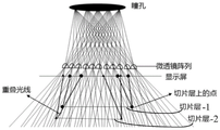
Fig. 3 shows the principle of acquiring and reconstructing an image of a conventional light field display microcell array. The principle of the acquisition unit image is that points on a three-dimensional object are imaged on recording equipment after passing through a micro-lens, and the image on the recording equipment is composed of pixel points on a display screen and the like. In the reconstruction of the traditional light field display micro-unit array image, the image part displayed by each pixel point on the display screen participates in the image reconstruction of the three-dimensional object, so the acquisition and calculation of the three-dimensional object image before reconstruction are quite complex.
In this embodiment, as shown in fig. 4, the application scenario of the actual device determines the information of the display screen 1 (including the size of the display screen 1 and the size of the sub-pixel 11) and the information of the microlens array 2 (including the radial size of the sub-microlens 21, the focal length of the sub-microlens 21, the radius of curvature of the sub-microlens 21, the refractive index of the sub-microlens 21, and the distance between the sub-microlens 21 and the display screen 1), and the pupil 3 position, the field angle, and the viewing distance are determined by calculation according to the information of the display screen 1 and the information of the microlens array 2; according to the position of the pupil 3, the field angle and the viewing distance, the effective imaging area 4 and the ineffective imaging area 5 are determined by calculation. The sub-microlenses and corresponding pixel regions in the effective imaging area 4 participate in the acquisition and calculation of the image of the microcell array. The sub-micro-lenses and the corresponding pixel regions in the ineffective imaging area 5 do not participate in the acquisition and calculation of the micro-unit array image, and compared with the acquisition and calculation of the traditional light field display micro-unit array image, the acquisition and calculation of the micro-unit array image in the embodiment can improve the acquisition and calculation efficiency.
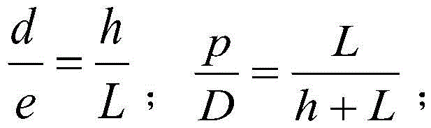
As shown in fig. 5, the information of the display screen 1 and the information of the microlens array 2 have the following relationship with the information of human eyes (including the position of the pupil 3 and the viewing distance):
wherein h is the distance between the micro-lens array 2 and the display screen 1; p is the radial dimension of the sub-microlenses; e is the distance between the viewpoints 31; l is the distance for the human eyes to watch the display screen 1; d is the sub-pixel size on the display screen 1; d is the pixel period on the display screen 1 corresponding to the microlens array 2. The position of the human eyes is right above the center of the display screen 1, and the field angle is within +/-15 degrees.
Step S13: each sub-micro lens in the effective imaging area corresponds to a plurality of sub-pixels on the display screen and processes the simulated light rays emitted by the sub-pixels to form a micro-unit light field.
And one sub-micro lens processes the light rays emitted by the corresponding sub-pixel to correspondingly form a micro-unit light field. A plurality of sub-micro lenses are correspondingly distributed in the effective imaging area, so that a plurality of micro-unit light fields are formed in the effective imaging area.
The method specifically comprises the following steps:
step S131: and obtaining the corresponding relation between each sub micro lens and the sub pixel of the display screen in the effective imaging area.
In this step, the determining factor of the corresponding relationship between each sub microlens and the display screen sub-pixel in the effective imaging area includes display screen information and microlens array information. It is noted that there is a many-to-one mapping relationship between the sub-pixels and the sub-microlenses. That is, the light emitted by each display sub-pixel corresponds to only one sub-micro lens; and one sub-microlens can process the light emitted by the plurality of display panel sub-pixels corresponding to the sub-microlens. And performing the coordinate system establishing processing on the light rays emitted by each sub-pixel in a simulating manner to obtain the light field information of the light rays emitted by each sub-pixel in the simulating manner.
Step S132: and combining the light field information of the light rays simulated by a plurality of sub-pixels corresponding to the sub-micro-lenses on the display screen to form the micro-unit light field of the sub-micro-lenses.
A plurality of sub-microlenses are correspondingly distributed in the effective imaging area, and a rectangular coordinate system which is formed by an X axis and a Y axis and is established in the plane of the microlens array and a Z axis which is vertical to the plane of the rectangular coordinate system are established; the origin of the space coordinate system is the center of the sub-microlens at the central position in the microlens array; the surface of the display screen is parallel to the surface of the micro lens array. If the whole microlens array is rectangular, the long side of the rectangle is taken as an X axis, the wide side of the rectangle is taken as a Y axis, and the center of the sub-microlens at the central position in the microlens array is taken as an origin to establish a space coordinate system. A plurality of micro-unit light fields are formed in the effective imaging area, and the light field information of each micro-unit light field is L _ Mij(x _ M, y _ M, z _ M, α _ pixel, β _ pixel); wherein X _ M is the X-axis coordinate of the sub-microlens in the space coordinate system; y _ M is the Y-axis coordinate of the sub-microlens in the space coordinate system; z _ M is the Z-axis coordinate of the sub-microlens in the space coordinate system;
wherein, X _ p is the X-axis coordinate of the corresponding sub-pixel of the sub-microlens on the display screen in the space coordinate system; y _ p is the Y-axis coordinate of the corresponding sub-pixel of the sub-microlens on the display screen in a space coordinate system; and Z _ p is the Z-axis coordinate of the corresponding sub-pixel of the sub-microlens on the display screen in a space coordinate system.
Step S14: and combining all the microcell light fields in the effective imaging area to obtain a pixel light field information database.
Wherein, the pixel light field information database is:
i is 1,2, … s; j is 1,2, … t. All the micro-unit light fields in the effective imaging area are combined, that is, all the micro-unit light fields obtained by simulating light rays emitted by the corresponding sub-pixels on the display screen by each sub-micro lens in the effective imaging area are stored in a database, that is, a pixel light field information database can be obtained, as shown in fig. 6, the pixel light field information database can realize the effects of screen entering (display screen 1) and screen exiting (display screen 1) of a 3D light field display image.
Step S2: processing to obtain a micro-unit array image of the original three-dimensional image at the slice image at the different depth of field positions according to the different depth of field positions of the original three-dimensional image, the slice images corresponding to the different depth of field positions and the pixel light field information at the different depth of field positions;
the method specifically comprises the following steps: as shown in figure 7 of the drawings,
step S21: a plurality of depth positions of the original three-dimensional image are acquired,
in this step, the original three-dimensional image may be obtained by using a light field camera or a computer, and in this embodiment, the original three-dimensional image is obtained by taking the example in which the computer generates slice images at different depth positions.
Step S22: the pixel light field information is projected to a plurality of depth of field positions of the original three-dimensional image.
In this step, the pixel light field information database established in step 1 is utilized to project the pixel light field information to a plurality of depth of field positions of the original three-dimensional image. The step can be specifically expressed as follows: according to the established pixel light field information database, in the pixel light field, each sub-pixel only records one light ray emitted by the sub-pixel through the corresponding micro-lens, namely, the light emitted by each sub-pixel comprises both position information and direction information. The light rays emitted by all the sub-pixels are mutually overlapped in the space to form a light ray field of the whole space. The light rays emitted by all sub-pixels may overlap at different depth positions. And selecting a plurality of depth of field positions of the original three-dimensional image, and projecting the pixel light field information to the depth of field positions.
Step S23: and simulating to light sub-pixels of the display screen according to the object point information on the original three-dimensional image in different depth-of-field images so as to generate a micro-unit array image corresponding to the slice image at the depth-of-field position.
In this step, the object point information is sub-pixel gray scale information in which the pixel gray scale on the slice image is not 0. When the slice image on the three-dimensional object is at a certain depth of field position, the light field intersects with the slice image at the depth of field position, the object point coordinates on the slice image are compared with the coordinates of the projected pixel light field at the depth of field position, the same coordinate position is found, and the gray scale information is assigned to the display screen sub-pixel corresponding to the intersection point light through reverse tracing.
And assigning the gray scale information of all the intersection points with the gray scale values not being 0 to the corresponding display screen sub-pixels to generate the microcell array image corresponding to the slice layer.
Following the method of step 2, for example, as shown in FIG. 8: a rectangle has four vertices and is in the same slice level with depth of field h 1. Projecting the pixel light field coordinates at the depth of field position h1 yields coordinates E (x _ E, y _ E, z _ E), where:
x_E=x_M+h1*sin(β_pixel)*cos(α_pixel)
y_E=y_M+h1*sin(β_pixel)*sin(α_pixel)
z_E=h1
comparing the coordinates of the vertex of the layer of rectangle with the coordinates E of the projected pixel light field at the position of the depth of field to find the same coordinate position; and then reversely tracing the position of the sub-pixel corresponding to the vertex by using the formula, and endowing the color gray scale information of the rectangular vertex to the corresponding sub-pixel.
In fig. 8, after all sub-pixel information corresponding to four points of the rectangle is assigned, the gray scale of the sub-pixel of the other display screen is 0, and finally the micro-cell array image of the rectangle under the depth of field is obtained.
Step S3: and superposing the micro-unit array images of the slice images of the original three-dimensional image at different depth of field positions to obtain the micro-unit array image of the original three-dimensional image.
In the step, when the multi-layer slice traces correspond to the display screen sub-pixels, the principle is to trace the corresponding display screen sub-pixels on object points on different slice images respectively to obtain the micro-unit array images of the slice images at different depth of field positions. And superposing the microcell array images of the slice images of the original three-dimensional image at different depth of field positions to obtain the microcell array image of the original three-dimensional image.
This step is, in particular, as shown in figure 9,
acquiring a micro-unit array image n for n slice images of the original three-dimensional image at different depth of field positions, namely acquiring a micro-unit array image after the 1 st operation;
obtaining a microcell array image (n-1);
superposing the microcell array image (n-1) and the microcell array image n to obtain a microcell array image after the 2 nd operation, which comprises the following specific steps:
judging whether each sub-pixel gray-scale value of the micro-unit array image (n-1) is 0 or not;
if the gray scale value of a sub-pixel of the micro-cell array image (n-1) is 0, the gray scale value of the sub-pixel at the position of the micro-cell array image after the 2 nd operation is set as the gray scale value of the sub-pixel position corresponding to the micro-cell array image after the 1 st operation;
if the gray level value of a sub-pixel of the micro-cell array image (n-1) is not 0, setting the gray level value of the sub-pixel at the position of the micro-cell array image after the 2 nd operation as the gray level value of the sub-pixel position corresponding to the micro-cell array image (n-1);
obtaining a 2 nd-operation micro-unit array image;
obtaining a microcell array image (n-2);
superposing the micro-unit array image (n-2) and the micro-unit array image (n-1) to obtain a micro-unit array image after the 3 rd operation, which comprises the following specific steps:
judging whether each sub-pixel gray-scale value of the micro-unit array image (n-2) is 0 or not;
if the gray-scale value of a sub-pixel of the micro-unit array image (n-2) is 0, the gray-scale value of the sub-pixel at the position of the micro-unit array image after the 3 rd operation is set as the gray-scale value of the sub-pixel position corresponding to the micro-unit array image after the 2 nd operation;
if the gray level value of a sub-pixel of the micro-cell array image (n-2) is not 0, setting the gray level value of the sub-pixel at the position of the micro-cell array image after the 3 rd operation as the gray level value of the sub-pixel position corresponding to the micro-cell array image (n-2);
obtaining a microcell array image after the 3 rd operation;
repeating the above process to obtain the microcell array image after the nth operation, namely obtaining the microcell array image of the original three-dimensional image.
Where n denotes the number of slice images, and n is an integer greater than 1. For n slice images of the original three-dimensional image at different depth of field positions, wherein the slice image (m-1) and the slice image m are two arbitrary adjacent slice images, the slice image (m-1) is closer to the pupil position than the slice image m, and m is more than or equal to 2 and less than or equal to n;
each of the microcell array images is obtained by performing the steps S22, S23, S24 with its corresponding slice image.
The setting range of the limit value a is as follows: greater than or equal to 0 and less than the upper limit of the gray scale value.
For example, as shown in fig. 10, when the microcell array images of the slice images are superimposed, display screen sub-pixels corresponding to the same position as object points at different depth of field positions are encountered, and at this time, the gray scale assignment principle of the display screen sub-pixels follows the actual object shielding relationship, and assigns gray scale information of sub-pixels at the depth of field positions away from the pupil, as shown in fig. 10, overlapping light rays are used, the slice layer-1 and the slice layer-2 trace the same light ray, and when tracking the sub-pixels, the gray scale information of the slice layer-1 is assigned to the sub-pixels.
Example 3:
and carrying out noise reduction on the depth position image of the original three-dimensional image before simulating and lighting sub-pixels of a display screen on object point information on different depth images of the original three-dimensional image to generate a micro-unit array image corresponding to the slice image at the depth position. In this embodiment, an original three-dimensional image is obtained by taking a case where a computer generates slice images at different depth positions. The method for obtaining the microcell array image of the original three-dimensional image through slice image calculation comprises the following steps of: as shown in the figure 11 of the drawings,
for the slice images of n different depth-of-field positions of the original three-dimensional image, carrying out noise reduction processing on the slice image n: sequentially judging whether each sub-pixel gray-scale value of the slice image n is smaller than a limit value a or not;
if the gray level value of a sub-pixel of the slice image n is smaller than the limit value a, replacing the gray level value of the sub-pixel with 0;
if the gray level value of a sub-pixel of the slice image n is not less than the limit value a, the gray level value of the sub-pixel is unchanged;
tracking a noise reduction object point on the slice image n subjected to the noise reduction calculation corresponding to a screen sub-pixel to obtain a micro-unit array image n, and obtaining a micro-unit array image after the 1 st operation;
and (3) carrying out noise reduction processing on the slice image (n-1): sequentially judging whether the gray-scale value of each pixel of the slice image (n-1) is smaller than a limit value or not;
if the gray-scale value of a sub-pixel of the slice image (n-1) is smaller than the limit value a, replacing the gray-scale value of the sub-pixel with 0;
if the gray-scale value of a sub-pixel of the slice image (n-1) is not less than the limit value a, the gray-scale value of the sub-pixel is unchanged;
tracking a noise reduction object point on the slice image (n-1) subjected to the noise reduction calculation by a corresponding screen sub-pixel to obtain a micro-unit array image (n-1);
superposing the microcell array image (n-1) and the microcell array image n to obtain a microcell array image after the 2 nd operation, which comprises the following specific steps:
judging whether each sub-pixel gray-scale value of the micro-unit array image (n-1) is 0 or not;
if the gray-scale value of a sub-pixel of the micro-unit array image (n-1) is 0, the gray-scale value of the sub-pixel at the position of the micro-unit array image after the 2 nd operation is set as the gray-scale value of the sub-pixel position corresponding to the micro-unit array image after the 1 st operation;
if the gray level value of a sub-pixel of the micro-cell array image (n-1) is not 0, setting the gray level value of the sub-pixel at the position of the micro-cell array image after the 2 nd operation as the gray level value of the sub-pixel position corresponding to the micro-cell array image (n-1);
obtaining a 2 nd-operation micro-unit array image;
and (3) carrying out noise reduction processing on the slice image (n-2): sequentially judging whether the gray-scale value of each pixel of the slice image (n-2) is smaller than a limit value a or not;
if the gray-scale value of a sub-pixel of the slice image (n-2) is smaller than the limit value a, replacing the gray-scale value of the sub-pixel with 0;
if the gray-scale value of a sub-pixel of the slice image (n-2) is not less than the limit value a, the gray-scale value of the sub-pixel is unchanged;
tracking a noise reduction object point on the slice image (n-2) subjected to the noise reduction calculation by a corresponding screen sub-pixel to obtain a micro-unit array image (n-2);
superposing the micro-unit array image (n-2) and the micro-unit array image (n-1) to obtain a micro-unit array image after the 3 rd operation, which comprises the following specific steps:
judging whether each sub-pixel gray-scale value of the micro-unit array image (n-2) is 0 or not;
if the gray-scale value of a sub-pixel of the micro-unit array image (n-2) is 0, the gray-scale value of the sub-pixel at the position of the micro-unit array image after the 3 rd operation is set as the gray-scale value of the sub-pixel position corresponding to the micro-unit array image after the 2 nd operation;
if the gray level value of a sub-pixel of the micro-cell array image (n-2) is not 0, setting the gray level value of the sub-pixel at the position of the micro-cell array image after the 3 rd operation as the gray level value of the sub-pixel position corresponding to the micro-cell array image (n-2);
obtaining a microcell array image after the 3 rd operation;
repeating the above process to obtain the microcell array image after the nth operation, namely obtaining the microcell array image of the original three-dimensional image.
Where n denotes the number of slice images, and n is an integer greater than 1. For n slice images at different depth of field positions, wherein the slice image (m-1) and the slice image m are two arbitrary adjacent slice images, the slice image (m-1) is closer to the pupil position than the slice image m, and m is more than or equal to 2 and less than or equal to n;
in the embodiment, the noise reduction object point is defined as a sub-pixel of which the pixel gray scale is not 0 on the slice image after the noise reduction calculation;
the setting range of the limit value a is as follows: greater than or equal to 0 and less than the upper limit of the gray scale value.
It is understood that whether to perform noise reduction on a depth position image of the original three-dimensional image can be freely selected, and can also be determined according to the quality of the depth position image of the original three-dimensional image. The noise reduction may be selected to be performed only on slice images at one or more depth positions. Of course, performing noise reduction on slice images at multiple depth positions includes selecting to perform noise reduction on slice images at a portion of the depth positions, as well as performing noise reduction on slice images at all depth positions.
If the noise reduction operation is not performed on the slice image at the depth position, the slice image at the depth position may be directly performed to step S23, and the microcell array image corresponding to the slice image at the depth position may be obtained.
To better illustrate the operation effect of embodiment 3, as shown in fig. 12, the original three-dimensional image is composed of three B-letters with different color depths, which respectively correspond to different depth positions, and in order to present different depth effects, the three slice images have different positions and the same size corresponding to the letters; black represents no light field information in the drawing process, and the black is actually observed as a transparent area; in order to present the slicing effect, the background except the B letter is set to be transparent, and the actual two-dimensional image is black. The image of the microcell array corresponding to the slice image is finally displayed on the display screen.
As shown in fig. 13 and 14, the microcell array image of the slice image at the depth position 2 is superimposed on the microcell array image of the slice image at the depth position 3, and the microcell array image of the slice image at the depth position 1 is further superimposed on the image in which the microcell array image of the slice image at the depth position 2 is superimposed on the microcell array image of the slice image at the depth position 3.
After obtaining the microcell array image of the original three-dimensional image, providing the image to the display screen 1, displaying the display screen 1 according to the microcell array image, and enabling the display content to enter human eyes after passing through the microlens array 2 on the display side of the display screen 1, so that 3D display can be realized.
As shown in fig. 15, the display apparatus was tested for a test for actually testing the light field display effect. The experimental test display device adopts a 2.1inch color 3K display screen 1, a sub-pixel 11 is rectangular, the size of the sub-pixel 11 is 7.3um x 10.95um, the orthographic projection shape of a sub-micro lens 21 on the display screen 1 is regular hexagon, the side length size of the sub-micro lens 21 is 0.761mm, the curvature radius of the sub-micro lens 21 is 3.269mm, and the placing height (namely the distance between the sub-micro lens 21 and the display screen 1) is 9.5038 mm. The microlens array 2 is placed on the display side of the display screen 1, the display screen 1 loads the microcell array image, and the position of the microlens array 2 is adjusted so that a clear light field image can be observed.
The actual observed effect is shown in fig. 16. Three depth-of-field maps are respectively manufactured, the depth-of-field positions are respectively 200mm, 610mm and 1100mm, and a single lens reflex is used for replacing human eyes for observation. Meanwhile, large object images such as the simulated depth of field images are manufactured and are respectively placed at the corresponding depth of field positions. The single lens reflex is used for focusing images at different depth of field positions respectively, so that clear images at the positions can be obtained, images at other depth of field positions are fuzzy, and the monocular stereoscopic vision display effect is realized. In fig. 16, the upper virtual circle is the real image of the camera with the corresponding depth of field, and the lower virtual circle is the clearest image of the display with the corresponding depth of field.
Based on the light field display method, this embodiment further provides a light field display system, as shown in fig. 17, including: a database establishing module 101, configured to establish a pixel light field information database. The processing and acquiring module 102 is configured to process the original three-dimensional image to obtain a microcell array image of the original three-dimensional image at different depth-of-field positions according to different depth-of-field positions of the original three-dimensional image, slice images corresponding to the different depth-of-field positions, and pixel light field information at the different depth-of-field positions. The superposition obtaining module 103 is configured to superpose the microcell array images of the slice images of the original three-dimensional image at different depth of field positions to obtain a microcell array image of the original three-dimensional image.
Beneficial effects of examples 1-3: the light field display method provided in embodiments 1 to 3, where the pixel light field information database is established through calculation, and after the pixel light field information database is established, the microcell array images of the slice images of the original three-dimensional image at different depth of field positions and the microcell array images of the original three-dimensional image obtained through subsequent processing are obtained based on the calculation result in the pixel light field information database, and further calculation is not required, so that, compared with a conventional method for generating a microcell array image of an original three-dimensional image, the amount of calculation is reduced, and the efficiency of obtaining a microcell array image of an original three-dimensional image is improved.
Example 4
The present embodiment provides a storage medium storing the light field display system of embodiments 1 to 3, which is capable of executing the light field display method of embodiments 1 to 3.
The storage medium, by storing a light field display system capable of executing the light field display method in embodiments 1 to 3, can reduce the amount of calculation to obtain a microcell array image of an original three-dimensional image, and improve the efficiency of obtaining a microcell array image of the original three-dimensional image.
Example 5
The present embodiment provides a display panel including the storage medium of embodiment 4.
The display panel, by using the storage medium in embodiment 4, not only can realize light field display of three-dimensional stereo images and make human eyes watch the images without dizzy feeling, but also can reduce the calculation amount of obtaining the microcell array images of the original three-dimensional images and improve the efficiency of obtaining the microcell array images of the original three-dimensional images.
The display panel provided by the invention can be in the forms of LCD, OLED, QLED, miniLED, micro LED and the like, and the light field display method and system, the storage medium and the display panel provided by the invention can be used for any products or parts with display functions, such as televisions, displays, notebook computers, tablet computers, mobile phones, wearable equipment, navigators and the like.
It will be understood that the above embodiments are merely exemplary embodiments taken to illustrate the principles of the present invention, which is not limited thereto. It will be apparent to those skilled in the art that various modifications and improvements can be made without departing from the spirit and substance of the invention, and these modifications and improvements are also considered to be within the scope of the invention.