CN111249514A - A medical cotton ball processing equipment - Google Patents
A medical cotton ball processing equipment Download PDFInfo
- Publication number
- CN111249514A CN111249514A CN202010083381.XA CN202010083381A CN111249514A CN 111249514 A CN111249514 A CN 111249514A CN 202010083381 A CN202010083381 A CN 202010083381A CN 111249514 A CN111249514 A CN 111249514A
- Authority
- CN
- China
- Prior art keywords
- sliding
- seat
- pulley
- filtering
- belt pulley
- Prior art date
- Legal status (The legal status is an assumption and is not a legal conclusion. Google has not performed a legal analysis and makes no representation as to the accuracy of the status listed.)
- Granted
Links
Images




Classifications
-
- A—HUMAN NECESSITIES
- A61—MEDICAL OR VETERINARY SCIENCE; HYGIENE
- A61L—METHODS OR APPARATUS FOR STERILISING MATERIALS OR OBJECTS IN GENERAL; DISINFECTION, STERILISATION OR DEODORISATION OF AIR; CHEMICAL ASPECTS OF BANDAGES, DRESSINGS, ABSORBENT PADS OR SURGICAL ARTICLES; MATERIALS FOR BANDAGES, DRESSINGS, ABSORBENT PADS OR SURGICAL ARTICLES
- A61L11/00—Methods specially adapted for refuse
-
- A—HUMAN NECESSITIES
- A61—MEDICAL OR VETERINARY SCIENCE; HYGIENE
- A61L—METHODS OR APPARATUS FOR STERILISING MATERIALS OR OBJECTS IN GENERAL; DISINFECTION, STERILISATION OR DEODORISATION OF AIR; CHEMICAL ASPECTS OF BANDAGES, DRESSINGS, ABSORBENT PADS OR SURGICAL ARTICLES; MATERIALS FOR BANDAGES, DRESSINGS, ABSORBENT PADS OR SURGICAL ARTICLES
- A61L2/00—Disinfection or sterilisation of materials or objects, in general; Accessories therefor
- A61L2/16—Disinfection or sterilisation of materials or objects, in general; Accessories therefor using chemical substances
- A61L2/18—Liquid substances
-
- A—HUMAN NECESSITIES
- A61—MEDICAL OR VETERINARY SCIENCE; HYGIENE
- A61L—METHODS OR APPARATUS FOR STERILISING MATERIALS OR OBJECTS IN GENERAL; DISINFECTION, STERILISATION OR DEODORISATION OF AIR; CHEMICAL ASPECTS OF BANDAGES, DRESSINGS, ABSORBENT PADS OR SURGICAL ARTICLES; MATERIALS FOR BANDAGES, DRESSINGS, ABSORBENT PADS OR SURGICAL ARTICLES
- A61L2/00—Disinfection or sterilisation of materials or objects, in general; Accessories therefor
- A61L2/26—Accessories
-
- A—HUMAN NECESSITIES
- A61—MEDICAL OR VETERINARY SCIENCE; HYGIENE
- A61L—METHODS OR APPARATUS FOR STERILISING MATERIALS OR OBJECTS IN GENERAL; DISINFECTION, STERILISATION OR DEODORISATION OF AIR; CHEMICAL ASPECTS OF BANDAGES, DRESSINGS, ABSORBENT PADS OR SURGICAL ARTICLES; MATERIALS FOR BANDAGES, DRESSINGS, ABSORBENT PADS OR SURGICAL ARTICLES
- A61L2202/00—Aspects relating to methods or apparatus for disinfecting or sterilising materials or objects
- A61L2202/10—Apparatus features
- A61L2202/12—Apparatus for isolating biocidal substances from the environment
- A61L2202/123—Connecting means
Landscapes
- Health & Medical Sciences (AREA)
- Epidemiology (AREA)
- Life Sciences & Earth Sciences (AREA)
- Animal Behavior & Ethology (AREA)
- General Health & Medical Sciences (AREA)
- Public Health (AREA)
- Veterinary Medicine (AREA)
- Chemical & Material Sciences (AREA)
- Chemical Kinetics & Catalysis (AREA)
- General Chemical & Material Sciences (AREA)
- Filtration Of Liquid (AREA)
Abstract
本发明涉及一种棉球设备,更具体的说是一种医用棉球处理设备,包括酒精消毒机构、进给过滤机构、切换机构,设备能够帮助棉球顺畅进入设备内,设备能够用极少的酒精对棉球进行消毒,不会对酒精造成浪费,设备能够将废酒精和棉球分开排出,设备能够对废酒精进行过滤,设备能够自动排废酒精,所述的酒精消毒机构与进给过滤机构相连,进给过滤机构与切换机构相连,切换机构与酒精消毒机构相连。

The invention relates to a cotton ball equipment, more specifically a medical cotton ball processing equipment, which includes an alcohol disinfection mechanism, a feeding filter mechanism and a switching mechanism. The equipment can help the cotton balls enter the equipment smoothly, and the equipment can be used with very little The alcohol sterilizes the cotton balls without wasting alcohol. The equipment can separate the waste alcohol and the cotton balls. The equipment can filter the waste alcohol and the equipment can automatically discharge the waste alcohol. The alcohol disinfection mechanism and feeding The filtering mechanism is connected, the feeding filtering mechanism is connected with the switching mechanism, and the switching mechanism is connected with the alcohol disinfection mechanism.
Description
技术领域technical field
本发明涉及一种棉球设备,更具体的说是一种医用棉球处理设备。The invention relates to a cotton ball equipment, more specifically a medical cotton ball processing equipment.
背景技术Background technique
医用棉球在使用完毕后,如果不经过处理可能会造成二次污染,传统的酒精浸泡方式会造成酒精的极大浪费,所以设计了这种医用棉球处理设备。After the medical cotton ball is used, it may cause secondary pollution if it is not treated. The traditional alcohol soaking method will cause a great waste of alcohol, so this medical cotton ball processing equipment is designed.
发明内容SUMMARY OF THE INVENTION
本发明主要解决的技术问题是提供一种医用棉球处理设备,设备能够帮助棉球顺畅进入设备内,设备能够用极少的酒精对棉球进行消毒,不会对酒精造成浪费,设备能够将废酒精和棉球分开排出,设备能够对废酒精进行过滤,设备能够自动排废酒精。The main technical problem to be solved by the present invention is to provide a medical cotton ball processing equipment, the equipment can help the cotton balls to enter the equipment smoothly, the equipment can sterilize the cotton balls with very little alcohol, and the alcohol will not be wasted, and the equipment can Waste alcohol and cotton balls are discharged separately, the equipment can filter waste alcohol, and the equipment can automatically discharge waste alcohol.
为解决上述技术问题,本发明涉及一种棉球设备,更具体的说是一种医用棉球处理设备,包括酒精消毒机构、进给过滤机构、切换机构,设备能够帮助棉球顺畅进入设备内,设备能够用极少的酒精对棉球进行消毒,不会对酒精造成浪费,设备能够将废酒精和棉球分开排出,设备能够对废酒精进行过滤,设备能够自动排废酒精。In order to solve the above technical problems, the present invention relates to a cotton ball equipment, more specifically a medical cotton ball processing equipment, including an alcohol disinfection mechanism, a feeding filter mechanism, and a switching mechanism, and the equipment can help the cotton balls to enter the equipment smoothly. , the equipment can sterilize cotton balls with a very small amount of alcohol, without wasting alcohol, the equipment can separate waste alcohol and cotton balls, the equipment can filter waste alcohol, and the equipment can automatically drain waste alcohol.
所述的酒精消毒机构与进给过滤机构相连,进给过滤机构与切换机构相连,切换机构与酒精消毒机构相连。The alcohol disinfection mechanism is connected with the feed filter mechanism, the feed filter mechanism is connected with the switch mechanism, and the switch mechanism is connected with the alcohol disinfection mechanism.
作为本技术方案的进一步优化,本发明一种医用棉球处理设备所述的酒精消毒机构包括滑动斗机构、滑动驱动机构、机身机构、基座、酒精箱机构,滑动斗机构与滑动驱动机构相接触,滑动驱动机构与机身机构相连,机身机构与基座相连,酒精箱机构与机身机构相连;滑动斗机构包括配合槽轮、支撑、带孔阶梯座、滑动斗本体、进入口、出口,配合槽轮与支撑相连,支撑与带孔阶梯座相连,支撑与滑动斗本体相连,进入口设置在滑动斗本体上,出口设置在滑动斗本体上;滑动驱动机构包括十字座、开孔、铰接臂、电机、皮带轮、皮带、转动轮、传动皮带轮、传动轴,开孔开在十字座上,十字座与铰接臂相铰接,铰接臂与转动轮相铰接,转动轮与传动轴相连,传动轴与传动皮带轮相连,传动皮带轮与皮带挠性连接,皮带与皮带轮挠性连接,皮带轮与电机相连;机身机构包括立柱、轴承座、进液管、单向阀、横撑、十字槽、滑动柱、复位弹簧、机身本体、进入口、拐角轴承座、阶梯槽、竖向滑杆、竖向弹簧、出料斗、横向滑槽、出口、滑槽I、卸出口、光孔A,立柱与基座相连,立柱与机身本体相连,机身本体与进液管相连,单向阀设置在进液管内,横撑与机身本体相连,十字槽开在横撑上,十字槽与十字座滑动连接,开孔与滑动柱滑动连接,滑动柱与横撑相连,复位弹簧套在滑动柱上,复位弹簧抵在十字座上,进入口设置在机身本体上,拐角轴承座与机身本体相连,拐角轴承座与电机相连,传动轴与拐角轴承座的连接方式为轴承连接,阶梯槽开在机身本体上,竖向滑杆设置在阶梯槽内,竖向滑杆与机身本体相连,竖向弹簧套在竖向滑杆上,带孔阶梯座与竖向滑杆滑动连接,带孔阶梯座与阶梯槽滑动连接,竖向弹簧抵在带孔阶梯座上,出料斗与机身本体相连,横向滑槽开在出料斗上,出口开在出料斗上,滑槽I开在出料斗上,卸出口设置在出料斗上,卸出口将出口与机身本体内部相连通,光孔A开在出料斗上;酒精箱机构包括箱支腿、接口、酒精箱本体、接头进口,箱支腿与酒精箱本体相连,接口与酒精箱本体相连,接头进口与酒精箱本体相连,接口与进液管相连。As a further optimization of the technical solution, the alcohol disinfection mechanism described in the medical cotton ball processing equipment of the present invention includes a sliding bucket mechanism, a sliding driving mechanism, a body mechanism, a base, an alcohol tank mechanism, a sliding bucket mechanism and a sliding driving mechanism. In contact, the sliding drive mechanism is connected with the body mechanism, the body mechanism is connected with the base, and the alcohol tank mechanism is connected with the body mechanism; the sliding bucket mechanism includes a matching sheave, a support, a stepped seat with holes, a sliding bucket body, and an inlet port. , outlet, the matching sheave is connected with the support, the support is connected with the stepped seat with holes, the support is connected with the sliding bucket body, the inlet is set on the sliding bucket body, and the outlet is set on the sliding bucket body; the sliding drive mechanism includes a cross seat, an opening Holes, articulated arms, motors, pulleys, belts, rotating wheels, drive pulleys, drive shafts, openings are opened on the cross seat, the cross seat is hinged with the hinged arm, the hinged arm is hinged with the rotating wheel, and the rotating wheel is connected with the drive shaft , the drive shaft is connected with the drive pulley, the drive pulley is flexibly connected with the belt, the belt is flexibly connected with the pulley, and the pulley is connected with the motor; the body mechanism includes a column, a bearing seat, a liquid inlet pipe, a one-way valve, a cross brace, a cross groove , sliding column, return spring, body body, inlet, corner bearing seat, stepped groove, vertical sliding rod, vertical spring, discharge hopper, transverse chute, outlet, chute I, discharge port, light hole A, The upright column is connected with the base, the upright column is connected with the fuselage body, the fuselage body is connected with the liquid inlet pipe, the one-way valve is arranged in the liquid inlet pipe, the cross brace is connected with the main body of the fuselage, the cross groove is opened on the cross brace, and the cross groove is connected with the liquid inlet pipe. The cross seat is slidably connected, the opening is slidably connected to the sliding column, the sliding column is connected to the horizontal brace, the return spring is sleeved on the sliding column, the return spring is against the cross seat, the inlet is set on the body of the fuselage, and the corner bearing seat is connected to the machine body. The body is connected to the body, the corner bearing seat is connected to the motor, the connection between the drive shaft and the corner bearing seat is bearing connection, the stepped groove is opened on the body body, the vertical sliding rod is set in the stepped groove, and the vertical sliding rod is connected to the body. The body is connected, the vertical spring is sleeved on the vertical sliding rod, the stepped seat with holes is slidingly connected with the vertical sliding rod, the stepped seat with holes is slidingly connected with the stepped groove, the vertical spring is against the stepped seat with holes, and the discharge hopper is connected to the vertical sliding rod. The fuselage body is connected, the transverse chute is opened on the discharge hopper, the outlet is opened on the discharge hopper, the chute I is opened on the discharge hopper, the discharge port is arranged on the discharge hopper, and the discharge port communicates the outlet with the inside of the fuselage body, The light hole A is opened on the discharge hopper; the alcohol box mechanism includes box legs, an interface, an alcohol box body, and a joint inlet. The box legs are connected with the alcohol box body, the interface is connected with the alcohol box body, and the joint inlet is connected with the alcohol box body. The interface is connected with the liquid inlet pipe.
作为本技术方案的进一步优化,本发明一种医用棉球处理设备所述的进给过滤机构包括驱动电机、皮带轮I、驱动轴、轮、圆弧槽、皮带轮II、过滤叶轮机构、过滤进口、过滤箱、过滤出管、滑动阀、限位块、过滤轴承座、铰接臂I、限位圆盘、带孔座I、支撑弹簧I、连接杆、滑轮座、滑轮、液体流出长孔、液体出口,驱动电机与机身本体相连,驱动电机与皮带轮I相连,皮带轮I与驱动轴相连,驱动轴与轮相连,圆弧槽开在轮上,驱动轴与轴承座的连接方式为轴承连接,驱动轴与皮带轮II相连,皮带轮II与过滤叶轮机构挠性连接,过滤叶轮机构与过滤轴承座的连接方式为轴承连接,过滤轴承座与过滤箱相连,过滤进口开在过滤箱上,过滤出管与过滤箱相连,滑动阀与过滤出管滑动连接,限位块与过滤出管相连,滑动阀与铰接臂I相铰接,铰接臂I与滑轮座相铰接,滑轮座与连接杆相连,连接杆与限位圆盘相连,连接杆与带孔座I滑动连接,带孔座I与过滤箱相连,支撑弹簧I套在连接杆上,支撑弹簧I两端分别抵在带孔座I、滑轮座上,滑轮座与滑轮的连接方式为轴承连接,过滤箱与基座相连,液体流出长孔开在过滤出管上,液体出口开在过滤出管上,液体流出长孔将过滤箱内部与液体出口相连通;过滤叶轮机构包括皮带I、叶轮皮带轮、叶轮轴、过滤叶轮,皮带I与叶轮皮带轮挠性连接,皮带I与皮带轮II挠性连接,叶轮皮带轮与叶轮轴相连,叶轮轴与过滤轴承座的连接方式为轴承连接,叶轮轴与过滤叶轮相连。As a further optimization of the technical solution, the feeding and filtering mechanism of the medical cotton ball processing equipment of the present invention includes a drive motor, a pulley I, a drive shaft, a wheel, an arc groove, a pulley II, a filter impeller mechanism, a filter inlet, Filter box, filter outlet pipe, sliding valve, limit block, filter bearing seat, articulated arm I, limit disc, seat with hole I, support spring I, connecting rod, pulley seat, pulley, liquid outflow long hole, liquid At the exit, the drive motor is connected with the body of the fuselage, the drive motor is connected with the pulley I, the pulley I is connected with the drive shaft, the drive shaft is connected with the wheel, the arc groove is opened on the wheel, and the connection between the drive shaft and the bearing seat is bearing connection, The drive shaft is connected with the pulley II, the pulley II is flexibly connected with the filter impeller mechanism, the connection between the filter impeller mechanism and the filter bearing seat is bearing connection, the filter bearing seat is connected with the filter box, the filter inlet is opened on the filter box, and the filter outlet pipe It is connected with the filter box, the sliding valve is slidably connected with the filter outlet pipe, the limit block is connected with the filter outlet pipe, the sliding valve is hinged with the hinge arm I, the hinge arm I is hinged with the pulley seat, the pulley seat is connected with the connecting rod, and the connecting rod Connect with the limit disc, the connecting rod is slidably connected with the hole seat I, the hole seat I is connected with the filter box, the support spring I is sleeved on the connecting rod, and the two ends of the support spring I are respectively against the hole seat I and the pulley seat. The connection between the pulley seat and the pulley is the bearing connection, the filter box is connected with the base, the liquid outflow long hole is opened on the filter outlet pipe, the liquid outlet is opened on the filter outlet pipe, and the liquid outflow long hole connects the inside of the filter box with the liquid. The outlet is connected; the filter impeller mechanism includes a belt I, an impeller pulley, an impeller shaft, and a filter impeller. The belt I is flexibly connected to the impeller pulley, the belt I is flexibly connected to the pulley II, the impeller pulley is connected to the impeller shaft, and the impeller shaft is connected to the filter bearing. The connection mode of the seat is bearing connection, and the impeller shaft is connected with the filter impeller.
作为本技术方案的进一步优化,本发明一种医用棉球处理设备所述的切换机构包括轴承座A、异形座、棘齿、轴A、不完全棘轮、皮带轮A、皮带A、连接柱座、连接柱、复位弹簧I、过滤孔I、活动板、漏出开口、下连接板、限位滑柱、凸起条、废液斗、棉球斗、排废液进口、排棉球进口、排废液出口、排棉球出口,轴承座A与过滤箱相连,异形座与棘齿相连,棘齿与不完全棘轮相啮合,不完全棘轮与轴A相连,轴A与轴承座A的连接方式轴承连接,轴A与皮带轮A相连,皮带轮A与皮带A挠性连接,皮带A与皮带轮I挠性连接,异形座与连接柱座相连,连接柱座与连接柱相连,连接柱与活动板相连,复位弹簧I套在连接柱上,光孔A与连接柱滑动连接,复位弹簧I两端抵在活动板、出料斗上,过滤孔I开在活动板上,活动板与横向滑槽滑动连接,漏出开口开在活动板上,下连接板与连接柱座相连,下连接板与限位滑柱相连,限位滑柱与废液斗相连,废液斗与棉球斗相连,凸起条与废液斗相连,凸起条与棉球斗相连,凸起条与滑槽I滑动连接,排废液进口设置在废液斗上,排棉球进口设置在棉球斗上,排废液出口设置在废液斗上,排棉球出口设置在棉球斗上。As a further optimization of the technical solution, the switching mechanism described in the medical cotton ball processing equipment of the present invention includes a bearing seat A, a special-shaped seat, a ratchet tooth, a shaft A, an incomplete ratchet wheel, a pulley A, a belt A, a connecting column seat, Connecting column, return spring I, filter hole I, movable plate, leakage opening, lower connecting plate, limit spool, raised strip, waste liquid hopper, cotton ball hopper, waste liquid inlet, cotton ball inlet, waste discharge The liquid outlet, the cotton discharge ball outlet, the bearing seat A is connected to the filter box, the special-shaped seat is connected to the ratchet, the ratchet is meshed with the incomplete ratchet, the incomplete ratchet is connected to the shaft A, and the shaft A is connected to the bearing seat A. Bearing Connection, the shaft A is connected with the pulley A, the pulley A is flexibly connected with the belt A, the belt A is flexibly connected with the pulley I, the special-shaped seat is connected with the connecting column seat, the connecting column seat is connected with the connecting column, and the connecting column is connected with the movable plate, The return spring I is sleeved on the connecting column, the light hole A is slidably connected with the connecting column, the two ends of the return spring I abut on the movable plate and the discharge hopper, the filter hole I is opened on the movable plate, and the movable plate is slidably connected with the transverse chute, The leakage opening is opened on the movable plate, the lower connecting plate is connected with the connecting column base, the lower connecting plate is connected with the limit slide column, the limit slide column is connected with the waste liquid hopper, the waste liquid hopper is connected with the cotton ball hopper, and the raised strip is connected with The waste liquid hopper is connected, the raised strip is connected with the cotton ball hopper, the raised strip is slidably connected with the chute I, the waste liquid inlet is arranged on the waste liquid hopper, the cotton ball inlet is arranged on the cotton ball hopper, and the waste liquid outlet is arranged on the waste liquid hopper. It is arranged on the waste liquid bucket, and the outlet of the cotton ball is arranged on the cotton ball bucket.
作为本技术方案的进一步优化,本发明一种医用棉球处理设备所述的皮带轮I的半径是皮带轮A的6倍。As a further optimization of the technical solution, the radius of the pulley I described in a medical cotton ball processing device of the present invention is 6 times that of the pulley A.
本发明一种医用棉球处理设备的有益效果为:The beneficial effects of the medical cotton ball processing equipment of the present invention are:
本发明一种医用棉球处理设备,设备能够帮助棉球顺畅进入设备内,设备能够用极少的酒精对棉球进行消毒,不会对酒精造成浪费,设备能够将废酒精和棉球分开排出,设备能够对废酒精进行过滤,设备能够自动排废酒精。The invention is a medical cotton ball processing equipment, the equipment can help the cotton balls to enter the equipment smoothly, the equipment can sterilize the cotton balls with very little alcohol, and the alcohol will not be wasted, and the equipment can separate waste alcohol and cotton balls. , the equipment can filter waste alcohol, and the equipment can automatically discharge waste alcohol.
附图说明Description of drawings
下面结合附图和具体实施方法对本发明做进一步详细的说明。The present invention will be described in further detail below with reference to the accompanying drawings and specific implementation methods.
图1为本发明一种医用棉球处理设备的结构示意图一。FIG. 1 is a schematic structural diagram 1 of a medical cotton ball processing equipment according to the present invention.
图2为本发明一种医用棉球处理设备的结构示意图二。FIG. 2 is a second structural schematic diagram of a medical cotton ball processing equipment according to the present invention.
图3为本发明一种医用棉球处理设备的结构示意图三。FIG. 3 is a third structural schematic diagram of a medical cotton ball processing equipment according to the present invention.
图4为本发明一种医用棉球处理设备的酒精消毒机构1的结构示意图一。FIG. 4 is a first structural schematic diagram of an
图5为本发明一种医用棉球处理设备的酒精消毒机构1的结构示意图二。FIG. 5 is a second structural schematic diagram of the
图6为本发明一种医用棉球处理设备的酒精消毒机构1的结构示意图三。FIG. 6 is a third structural schematic diagram of an
图7为本发明一种医用棉球处理设备的滑动斗机构1-1的结构示意图。FIG. 7 is a schematic structural diagram of a sliding bucket mechanism 1-1 of a medical cotton ball processing equipment according to the present invention.
图8为本发明一种医用棉球处理设备的滑动驱动机构1-2的结构示意图。FIG. 8 is a schematic structural diagram of a sliding drive mechanism 1-2 of a medical cotton ball processing device according to the present invention.
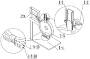
图9为本发明一种医用棉球处理设备的机身机构1-3的结构示意图。FIG. 9 is a schematic structural diagram of a body mechanism 1-3 of a medical cotton ball processing device of the present invention.
图10为本发明一种医用棉球处理设备的酒精箱机构1-5的结构示意图。FIG. 10 is a schematic structural diagram of the alcohol tank mechanism 1-5 of a medical cotton ball processing device of the present invention.
图11为本发明一种医用棉球处理设备的进给过滤机构2的结构示意图一。FIG. 11 is a first structural schematic diagram of the
图12为本发明一种医用棉球处理设备的进给过滤机构2的结构示意图二。FIG. 12 is a second structural schematic diagram of the feeding and
图13为本发明一种医用棉球处理设备的进给过滤机构2的结构示意图三。FIG. 13 is a third structural schematic diagram of the feeding and
图14为本发明一种医用棉球处理设备的进给过滤机构2的结构示意图四。FIG. 14 is a fourth schematic structural diagram of the feeding and
图15为本发明一种医用棉球处理设备的过滤叶轮机构2-7的结构示意图。Fig. 15 is a schematic structural diagram of the filter impeller mechanism 2-7 of a medical cotton ball processing device of the present invention.
图16为本发明一种医用棉球处理设备的切换机构3的结构示意图一。FIG. 16 is a first structural schematic diagram of the
图17为本发明一种医用棉球处理设备的切换机构3的结构示意图二。FIG. 17 is a second structural schematic diagram of the
图18为本发明一种医用棉球处理设备的切换机构3的结构示意图三。FIG. 18 is a third structural schematic diagram of the
图19为本发明一种医用棉球处理设备的切换机构3的结构示意图四。FIG. 19 is a fourth structural schematic diagram of the
图中:酒精消毒机构1;滑动斗机构1-1;配合槽轮1-1-1;支撑1-1-2;带孔阶梯座1-1-3;滑动斗本体1-1-4;进入口1-1-5;出口1-1-6;滑动驱动机构1-2;十字座1-2-1;开孔1-2-2;铰接臂1-2-3;电机1-2-4;皮带轮1-2-5;皮带1-2-6;转动轮1-2-7;传动皮带轮1-2-8;传动轴1-2-9;机身机构1-3;立柱1-3-1;轴承座1-3-2;进液管1-3-3;单向阀1-3-4;横撑1-3-5;十字槽1-3-6;滑动柱1-3-7;复位弹簧1-3-8;机身本体1-3-9;进入口1-3-10;拐角轴承座1-3-11;阶梯槽1-3-12;竖向滑杆1-3-13;竖向弹簧1-3-14;出料斗1-3-15;横向滑槽1-3-16;出口1-3-17;滑槽I1-3-18;卸出口1-3-19;光孔A1-3-20;基座1-4;酒精箱机构1-5;箱支腿1-5-1;接口1-5-2;酒精箱本体1-5-3;接头进口1-5-4;进给过滤机构2;驱动电机2-1;皮带轮I2-2;驱动轴2-3;轮2-4;圆弧槽2-5;皮带轮II2-6;过滤叶轮机构2-7;皮带I2-7-1;叶轮皮带轮2-7-2;叶轮轴2-7-3;过滤叶轮2-7-4;过滤进口2-8;过滤箱2-9;过滤出管2-10;滑动阀2-11;限位块2-12;过滤轴承座2-13;铰接臂I2-14;限位圆盘2-15;带孔座I2-16;支撑弹簧I2-17;连接杆2-18;滑轮座2-19;滑轮2-20;液体流出长孔2-21;液体出口2-22;切换机构3;轴承座A3-1;异形座3-2;棘齿3-3;轴A3-4;不完全棘轮3-5;皮带轮A3-6;皮带A3-7;连接柱座3-8;连接柱3-9;复位弹簧I3-10;过滤孔I3-11;活动板3-12;漏出开口3-13;下连接板3-14;限位滑柱3-15;凸起条3-16;废液斗3-17;棉球斗3-18;排废液进口3-19;排棉球进口3-20;排废液出口3-21;排棉球出口3-22。In the figure:
具体实施方式Detailed ways
具体实施方式一:Specific implementation one:
下面结合图1、图2、图3、图4、图5、图6、图7、图8、图9、图10、图11、图12、图13、图14、图15、图16、图17、图18、图19说明本实施方式,本发明涉及一种棉球设备,更具体的说是一种医用棉球处理设备,包括酒精消毒机构1、进给过滤机构2、切换机构3,设备能够帮助棉球顺畅进入设备内,设备能够用极少的酒精对棉球进行消毒,不会对酒精造成浪费,设备能够将废酒精和棉球分开排出,设备能够对废酒精进行过滤,设备能够自动排废酒精。Below in conjunction with Figure 1, Figure 2, Figure 3, Figure 4, Figure 5, Figure 6, Figure 7, Figure 8, Figure 9, Figure 10, Figure 11, Figure 12, Figure 13, Figure 14, Figure 15, Figure 16, Figure 17, Figure 18, Figure 19 illustrate this embodiment, the present invention relates to a cotton ball equipment, more specifically a medical cotton ball processing equipment, including an
所述的酒精消毒机构1与进给过滤机构2相连,进给过滤机构2与切换机构3相连,切换机构3与酒精消毒机构1相连。The
具体实施方式二:Specific implementation two:
下面结合图1、图2、图3、图4、图5、图6、图7、图8、图9、图10、图11、图12、图13、图14、图15、图16、图17、图18、图19说明本实施方式,本实施方式对实施方式一作进一步说明,所述的酒精消毒机构1包括滑动斗机构1-1、滑动驱动机构1-2、机身机构1-3、基座1-4、酒精箱机构1-5,滑动斗机构1-1与滑动驱动机构1-2相接触,滑动驱动机构1-2与机身机构1-3相连,机身机构1-3与基座1-4相连,酒精箱机构1-5与机身机构1-3相连;滑动斗机构1-1包括配合槽轮1-1-1、支撑1-1-2、带孔阶梯座1-1-3、滑动斗本体1-1-4、进入口1-1-5、出口1-1-6,配合槽轮1-1-1与支撑1-1-2相连,支撑1-1-2与带孔阶梯座1-1-3相连,支撑1-1-2与滑动斗本体1-1-4相连,进入口1-1-5设置在滑动斗本体1-1-4上,出口1-1-6设置在滑动斗本体1-1-4上;滑动驱动机构1-2包括十字座1-2-1、开孔1-2-2、铰接臂1-2-3、电机1-2-4、皮带轮1-2-5、皮带1-2-6、转动轮1-2-7、传动皮带轮1-2-8、传动轴1-2-9,开孔1-2-2开在十字座1-2-1上,十字座1-2-1与铰接臂1-2-3相铰接,铰接臂1-2-3与转动轮1-2-7相铰接,转动轮1-2-7与传动轴1-2-9相连,传动轴1-2-9与传动皮带轮1-2-8相连,传动皮带轮1-2-8与皮带1-2-6挠性连接,皮带1-2-6与皮带轮1-2-5挠性连接,皮带轮1-2-5与电机1-2-4相连;机身机构1-3包括立柱1-3-1、轴承座1-3-2、进液管1-3-3、单向阀1-3-4、横撑1-3-5、十字槽1-3-6、滑动柱1-3-7、复位弹簧1-3-8、机身本体1-3-9、进入口1-3-10、拐角轴承座1-3-11、阶梯槽1-3-12、竖向滑杆1-3-13、竖向弹簧1-3-14、出料斗1-3-15、横向滑槽1-3-16、出口1-3-17、滑槽I1-3-18、卸出口1-3-19、光孔A1-3-20,立柱1-3-1与基座1-4相连,立柱1-3-1与机身本体1-3-9相连,机身本体1-3-9与进液管1-3-3相连,单向阀1-3-4设置在进液管1-3-3内,横撑1-3-5与机身本体1-3-9相连,十字槽1-3-6开在横撑1-3-5上,十字槽1-3-6与十字座1-2-1滑动连接,开孔1-2-2与滑动柱1-3-7滑动连接,滑动柱1-3-7与横撑1-3-5相连,复位弹簧1-3-8套在滑动柱1-3-7上,复位弹簧1-3-8抵在十字座1-2-1上,进入口1-3-10设置在机身本体1-3-9上,拐角轴承座1-3-11与机身本体1-3-9相连,拐角轴承座1-3-11与电机1-2-4相连,传动轴1-2-9与拐角轴承座1-3-11的连接方式为轴承连接,阶梯槽1-3-12开在机身本体1-3-9上,竖向滑杆1-3-13设置在阶梯槽1-3-12内,竖向滑杆1-3-13与机身本体1-3-9相连,竖向弹簧1-3-14套在竖向滑杆1-3-13上,带孔阶梯座1-1-3与竖向滑杆1-3-13滑动连接,带孔阶梯座1-1-3与阶梯槽1-3-12滑动连接,竖向弹簧1-3-14抵在带孔阶梯座1-1-3上,出料斗1-3-15与机身本体1-3-9相连,横向滑槽1-3-16开在出料斗1-3-15上,出口1-3-17开在出料斗1-3-15上,滑槽I1-3-18开在出料斗1-3-15上,卸出口1-3-19设置在出料斗1-3-15上,卸出口1-3-19将出口1-3-17与机身本体1-3-9内部相连通,光孔A1-3-20开在出料斗1-3-15上;酒精箱机构1-5包括箱支腿1-5-1、接口1-5-2、酒精箱本体1-5-3、接头进口1-5-4,箱支腿1-5-1与酒精箱本体1-5-3相连,接口1-5-2与酒精箱本体1-5-3相连,接头进口1-5-4与酒精箱本体1-5-3相连,接口1-5-2与进液管1-3-3相连。Below in conjunction with Figure 1, Figure 2, Figure 3, Figure 4, Figure 5, Figure 6, Figure 7, Figure 8, Figure 9, Figure 10, Figure 11, Figure 12, Figure 13, Figure 14, Figure 15, Figure 16, Figures 17, 18, and 19 illustrate this embodiment. This embodiment further describes
具体实施方式三:Specific implementation three:
下面结合图1、图2、图3、图4、图5、图6、图7、图8、图9、图10、图11、图12、图13、图14、图15、图16、图17、图18、图19说明本实施方式,本实施方式对实施方式一作进一步说明,所述的进给过滤机构2包括驱动电机2-1、皮带轮I2-2、驱动轴2-3、轮2-4、圆弧槽2-5、皮带轮II2-6、过滤叶轮机构2-7、过滤进口2-8、过滤箱2-9、过滤出管2-10、滑动阀2-11、限位块2-12、过滤轴承座2-13、铰接臂I2-14、限位圆盘2-15、带孔座I2-16、支撑弹簧I2-17、连接杆2-18、滑轮座2-19、滑轮2-20、液体流出长孔2-21、液体出口2-22,驱动电机2-1与机身本体1-3-9相连,驱动电机2-1与皮带轮I2-2相连,皮带轮I2-2与驱动轴2-3相连,驱动轴2-3与轮2-4相连,圆弧槽2-5开在轮2-4上,驱动轴2-3与轴承座1-3-2的连接方式为轴承连接,驱动轴2-3与皮带轮II2-6相连,皮带轮II2-6与过滤叶轮机构2-7挠性连接,过滤叶轮机构2-7与过滤轴承座2-13的连接方式为轴承连接,过滤轴承座2-13与过滤箱2-9相连,过滤进口2-8开在过滤箱2-9上,过滤出管2-10与过滤箱2-9相连,滑动阀2-11与过滤出管2-10滑动连接,限位块2-12与过滤出管2-10相连,滑动阀2-11与铰接臂I2-14相铰接,铰接臂I2-14与滑轮座2-19相铰接,滑轮座2-19与连接杆2-18相连,连接杆2-18与限位圆盘2-15相连,连接杆2-18与带孔座I2-16滑动连接,带孔座I2-16与过滤箱2-9相连,支撑弹簧I2-17套在连接杆2-18上,支撑弹簧I2-17两端分别抵在带孔座I2-16、滑轮座2-19上,滑轮座2-19与滑轮2-20的连接方式为轴承连接,过滤箱2-9与基座1-4相连,液体流出长孔2-21开在过滤出管2-10上,液体出口2-22开在过滤出管2-10上,液体流出长孔2-21将过滤箱2-9内部与液体出口2-22相连通,不会对酒精造成浪费,在设备使用时,接头进口1-5-4外接进酒精的龙头,使酒精箱本体1-5-3内的酒精含量保证一直是满的状态,运转驱动电机2-1带动皮带轮I2-2进行转动,皮带轮I2-2进行转动会通过驱动轴2-3带动轮2-4进行转动,当棉球落入到圆弧槽2-5内,圆弧槽2-5随着轮2-4转动到进液管1-3-3的位置时,由于圆弧槽2-5与进液管1-3-3接通,导致进液管1-3-3的压力变下,这样单向阀1-3-4不足以平衡酒精箱本体1-5-3内的压力,这样酒精箱本体1-5-3内的液体会冲开单向阀1-3-4,酒精流进圆弧槽2-5内,然后压力平衡后,单向阀1-3-4关闭,这样进入到圆弧槽2-5内的酒精就会对棉球进行消毒,且量不大,可以起到节省酒精的作用;过滤叶轮机构2-7包括皮带I2-7-1、叶轮皮带轮2-7-2、叶轮轴2-7-3、过滤叶轮2-7-4,皮带I2-7-1与叶轮皮带轮2-7-2挠性连接,皮带I2-7-1与皮带轮II2-6挠性连接,叶轮皮带轮2-7-2与叶轮轴2-7-3相连,叶轮轴2-7-3与过滤轴承座2-13的连接方式为轴承连接,叶轮轴2-7-3与过滤叶轮2-7-4相连,通过驱动轴2-3在转动时会带动皮带轮II2-6进行转动,皮带轮II2-6进行转动会通过皮带I2-7-1带动叶轮皮带轮2-7-2进行转动,叶轮皮带轮2-7-2进行转动会带动过滤叶轮2-7-4进行转动,过滤叶轮2-7-4进行转动会对废液进行过滤;设备能够自动排废酒精,在异形座3-2往复运动时会推动滑轮2-20,滑轮2-20会带动滑轮座2-19向下运动,滑轮座2-19会通过铰接臂I2-14推动滑动阀2-11进行运动,滑动阀2-11进行运动会使液体出口2-22与外界接通,这样可以间歇对过滤后的废液进行排放。Below in conjunction with Figure 1, Figure 2, Figure 3, Figure 4, Figure 5, Figure 6, Figure 7, Figure 8, Figure 9, Figure 10, Figure 11, Figure 12, Figure 13, Figure 14, Figure 15, Figure 16, Figures 17, 18, and 19 illustrate this embodiment, which further describes
具体实施方式四:Specific implementation four:
下面结合图1、图2、图3、图4、图5、图6、图7、图8、图9、图10、图11、图12、图13、图14、图15、图16、图17、图18、图19说明本实施方式,本实施方式对实施方式一作进一步说明,所述的切换机构3包括轴承座A3-1、异形座3-2、棘齿3-3、轴A3-4、不完全棘轮3-5、皮带轮A3-6、皮带A3-7、连接柱座3-8、连接柱3-9、复位弹簧I3-10、过滤孔I3-11、活动板3-12、漏出开口3-13、下连接板3-14、限位滑柱3-15、凸起条3-16、废液斗3-17、棉球斗3-18、排废液进口3-19、排棉球进口3-20、排废液出口3-21、排棉球出口3-22,轴承座A3-1与过滤箱2-9相连,异形座3-2与棘齿3-3相连,棘齿3-3与不完全棘轮3-5相啮合,不完全棘轮3-5与轴A3-4相连,轴A3-4与轴承座A3-1的连接方式轴承连接,轴A3-4与皮带轮A3-6相连,皮带轮A3-6与皮带A3-7挠性连接,皮带A3-7与皮带轮I2-2挠性连接,异形座3-2与连接柱座3-8相连,连接柱座3-8与连接柱3-9相连,连接柱3-9与活动板3-12相连,复位弹簧I3-10套在连接柱3-9上,光孔A1-3-20与连接柱3-9滑动连接,复位弹簧I3-10两端抵在活动板3-12、出料斗1-3-15上,过滤孔I3-11开在活动板3-12上,活动板3-12与横向滑槽1-3-16滑动连接,漏出开口3-13开在活动板3-12上,下连接板3-14与连接柱座3-8相连,下连接板3-14与限位滑柱3-15相连,限位滑柱3-15与废液斗3-17相连,废液斗3-17与棉球斗3-18相连,凸起条3-16与废液斗3-17相连,凸起条3-16与棉球斗3-18相连,凸起条3-16与滑槽I1-3-18滑动连接,排废液进口3-19设置在废液斗3-17上,排棉球进口3-20设置在棉球斗3-18上,排废液出口3-21设置在废液斗3-17上,排棉球出口3-22设置在棉球斗3-18上,存有酒精和棉球的圆弧槽2-5转动到卸出口1-3-19处时,废液会从过滤孔I3-11漏出,从排废液进口3-19进入到废液斗3-17内,然后从排废液出口3-21、过滤进口2-8进入到过滤箱2-9内,且此时由于是上一个圆弧槽2-5转动到卸出口1-3-19处时,皮带轮I2-2转动了六分之一周,皮带轮I2-2会带动皮带轮A3-6转动一周,这样在圆弧槽2-5运动到卸出口1-3-19时,过滤孔I3-11刚好是在圆弧槽2-5的正下方,而随着皮带轮I2-2继续转动六分之一周时会带动皮带轮A3-6进行转动一周,皮带轮A3-6会带动不完全棘轮3-5转动一周,不完全棘轮3-5会通过棘齿3-3的啮合带动异形座3-2进行运动,异形座3-2会带动连接柱座3-8进行运动,连接柱座3-8进行运动会带动活动板3-12进行运动,活动板3-12进行运动会将漏出开口3-13与卸出口1-3-19接通,这样棉球会从卸出口1-3-19经过漏出开口3-13、排棉球进口3-20进入到棉球斗3-18内,从排棉球出口3-22排出,然后在不完全棘轮3-5运动到没有棘齿的部分时,复位弹簧I3-10会进行回弹带动活动板3-12复位,便于下一个圆弧槽2-5排放酒精和棉球。Below in conjunction with Figure 1, Figure 2, Figure 3, Figure 4, Figure 5, Figure 6, Figure 7, Figure 8, Figure 9, Figure 10, Figure 11, Figure 12, Figure 13, Figure 14, Figure 15, Figure 16, 17 , 18 , and 19 illustrate this embodiment, which further describes
具体实施方式五:Specific implementation five:
下面结合图1、图2、图3、图4、图5、图6、图7、图8、图9、图10、图11、图12、图13、图14、图15、图16、图17、图18、图19说明本实施方式,本实施方式对实施方式一作进一步说明,所述的皮带轮I2-2的半径是皮带轮A3-6的6倍。Below in conjunction with Figure 1, Figure 2, Figure 3, Figure 4, Figure 5, Figure 6, Figure 7, Figure 8, Figure 9, Figure 10, Figure 11, Figure 12, Figure 13, Figure 14, Figure 15, Figure 16, FIG. 17 , FIG. 18 , and FIG. 19 illustrate this embodiment, which further describes the first embodiment. The radius of the pulley I2-2 is 6 times that of the pulley A3-6.
本设备的工作原理为:设备能够帮助棉球顺畅进入设备内,通过电机1-2-4运转带动皮带轮1-2-5进行转动,皮带轮1-2-5进行转动会通过皮带1-2-6带动传动皮带轮1-2-8进行转动,传动皮带轮1-2-8进行转动会通过传动轴1-2-9带动转动轮1-2-7进行转动,转动轮1-2-7进行转动会通过铰接臂1-2-3带动十字座1-2-1在十字槽1-3-6内往复运动,铰接臂1-2-3在此过程中会反复向下压配合槽轮1-1-1,配合槽轮1-1-1会带动滑动斗本体1-1-4向下运动时会通过带孔阶梯座1-1-3对竖向弹簧1-3-14进行压缩,然后又在竖向弹簧1-3-14的回弹作用下带动滑动斗本体1-1-4向上运动,滑动斗本体1-1-4在进行上下往复运动的过程中会帮助棉球向下运动,这样可以保证棉球顺畅的进入到机身本体1-3-9内;设备能够用极少的酒精对棉球进行消毒,不会对酒精造成浪费,在设备使用时,接头进口1-5-4外接进酒精的龙头,使酒精箱本体1-5-3内的酒精含量保证一直是满的状态,运转驱动电机2-1带动皮带轮I2-2进行转动,皮带轮I2-2进行转动会通过驱动轴2-3带动轮2-4进行转动,当棉球落入到圆弧槽2-5内,圆弧槽2-5随着轮2-4转动到进液管1-3-3的位置时,由于圆弧槽2-5与进液管1-3-3接通,导致进液管1-3-3的压力变下,这样单向阀1-3-4不足以平衡酒精箱本体1-5-3内的压力,这样酒精箱本体1-5-3内的液体会冲开单向阀1-3-4,酒精流进圆弧槽2-5内,然后压力平衡后,单向阀1-3-4关闭,这样进入到圆弧槽2-5内的酒精就会对棉球进行消毒,且量不大,可以起到节省酒精的作用;设备能够将废酒精和棉球分开排出,存有酒精和棉球的圆弧槽2-5转动到卸出口1-3-19处时,废液会从过滤孔I3-11漏出,从排废液进口3-19进入到废液斗3-17内,然后从排废液出口3-21、过滤进口2-8进入到过滤箱2-9内,且此时由于是上一个圆弧槽2-5转动到卸出口1-3-19处时,皮带轮I2-2转动了六分之一周,皮带轮I2-2会带动皮带轮A3-6转动一周,这样在圆弧槽2-5运动到卸出口1-3-19时,过滤孔I3-11刚好是在圆弧槽2-5的正下方,而随着皮带轮I2-2继续转动六分之一周时会带动皮带轮A3-6进行转动一周,皮带轮A3-6会带动不完全棘轮3-5转动一周,不完全棘轮3-5会通过棘齿3-3的啮合带动异形座3-2进行运动,异形座3-2会带动连接柱座3-8进行运动,连接柱座3-8进行运动会带动活动板3-12进行运动,活动板3-12进行运动会将漏出开口3-13与卸出口1-3-19接通,这样棉球会从卸出口1-3-19经过漏出开口3-13、排棉球进口3-20进入到棉球斗3-18内,从排棉球出口3-22排出,然后在不完全棘轮3-5运动到没有棘齿的部分时,复位弹簧I3-10会进行回弹带动活动板3-12复位,便于下一个圆弧槽2-5排放酒精和棉球;设备能够对废酒精进行过滤,通过驱动轴2-3在转动时会带动皮带轮II2-6进行转动,皮带轮II2-6进行转动会通过皮带I2-7-1带动叶轮皮带轮2-7-2进行转动,叶轮皮带轮2-7-2进行转动会带动过滤叶轮2-7-4进行转动,过滤叶轮2-7-4进行转动会对废液进行过滤;设备能够自动排废酒精,在异形座3-2往复运动时会推动滑轮2-20,滑轮2-20会带动滑轮座2-19向下运动,滑轮座2-19会通过铰接臂I2-14推动滑动阀2-11进行运动,滑动阀2-11进行运动会使液体出口2-22与外界接通,这样可以间歇对过滤后的废液进行排放。The working principle of this equipment is: the equipment can help the cotton balls to enter the equipment smoothly, and the pulley 1-2-5 is driven to rotate through the operation of the motor 1-2-4. 6 Drive the drive pulley 1-2-8 to rotate, the drive pulley 1-2-8 rotates, and the drive shaft 1-2-9 drives the rotating wheel 1-2-7 to rotate, and the rotating wheel 1-2-7 rotates It will drive the cross seat 1-2-1 to reciprocate in the cross groove 1-3-6 through the hinge arm 1-2-3, and the hinge arm 1-2-3 will repeatedly press down the sheave 1- 1-1, the matching sheave 1-1-1 will drive the sliding bucket body 1-1-4 to move downward, and the vertical spring 1-3-14 will be compressed through the stepped seat with holes 1-1-3, and then Under the rebound action of the vertical spring 1-3-14, the sliding bucket body 1-1-4 is driven to move upward, and the sliding bucket body 1-1-4 will help the cotton ball to move downward during the up and down reciprocating motion. , so as to ensure that the cotton balls can enter the body 1-3-9 smoothly; the equipment can sterilize the cotton balls with very little alcohol without wasting alcohol. When the equipment is in use, the joint inlets 1-5 -4 Connect the faucet of alcohol outside to ensure that the alcohol content in the alcohol tank body 1-5-3 is always full, run the drive motor 2-1 to drive the pulley I2-2 to rotate, and the pulley I2-2 rotates through the The drive shaft 2-3 drives the wheel 2-4 to rotate. When the cotton ball falls into the arc groove 2-5, the arc groove 2-5 rotates with the wheel 2-4 to the position of the liquid inlet pipe 1-3-3. When in position, since the arc groove 2-5 is connected with the liquid inlet pipe 1-3-3, the pressure of the liquid inlet pipe 1-3-3 changes, so the one-way valve 1-3-4 is not enough to balance the alcohol tank The pressure in the main body 1-5-3, so that the liquid in the alcohol tank main body 1-5-3 will flush the one-way valve 1-3-4, and the alcohol will flow into the arc groove 2-5, and then after the pressure is balanced, The check valve 1-3-4 is closed, so that the alcohol entering the arc groove 2-5 will sterilize the cotton ball, and the amount is not large, which can save alcohol; the equipment can remove waste alcohol and cotton The balls are discharged separately, and when the arc groove 2-5 containing alcohol and cotton balls is rotated to the discharge port 1-3-19, the waste liquid will leak out from the filter hole I3-11 and enter from the waste liquid inlet 3-19. into the waste liquid hopper 3-17, and then from the waste liquid outlet 3-21 and the filter inlet 2-8 into the filter box 2-9, and at this time, because the previous arc groove 2-5 rotates to the
当然,上述说明并非对本发明的限制,本发明也不仅限于上述举例,本技术领域的普通技术人员在本发明的实质范围内所做出的变化、改型、添加或替换,也属于本发明的保护范围。Of course, the above description does not limit the present invention, and the present invention is not limited to the above examples. Changes, modifications, additions or substitutions made by those of ordinary skill in the art within the essential scope of the present invention also belong to the present invention. protected range.
Claims (5)
Priority Applications (1)
| Application Number | Priority Date | Filing Date | Title |
|---|---|---|---|
| CN202010083381.XA CN111249514B (en) | 2020-02-09 | 2020-02-09 | Medical cotton ball treatment facility |
Applications Claiming Priority (1)
| Application Number | Priority Date | Filing Date | Title |
|---|---|---|---|
| CN202010083381.XA CN111249514B (en) | 2020-02-09 | 2020-02-09 | Medical cotton ball treatment facility |
Publications (2)
| Publication Number | Publication Date |
|---|---|
| CN111249514A true CN111249514A (en) | 2020-06-09 |
| CN111249514B CN111249514B (en) | 2021-01-15 |
Family
ID=70943020
Family Applications (1)
| Application Number | Title | Priority Date | Filing Date |
|---|---|---|---|
| CN202010083381.XA Active CN111249514B (en) | 2020-02-09 | 2020-02-09 | Medical cotton ball treatment facility |
Country Status (1)
| Country | Link |
|---|---|
| CN (1) | CN111249514B (en) |
Cited By (1)
| Publication number | Priority date | Publication date | Assignee | Title |
|---|---|---|---|---|
| CN115092521A (en) * | 2022-06-13 | 2022-09-23 | 吴建林 | Pre-dipping alcohol box for surgical operation |
Citations (6)
| Publication number | Priority date | Publication date | Assignee | Title |
|---|---|---|---|---|
| GB2320036A (en) * | 1996-12-03 | 1998-06-10 | Hall Edward Ltd | Increasing absorbency of cotton |
| WO2014063013A1 (en) * | 2012-10-18 | 2014-04-24 | The University Of Akron | Apparatus and method for electrospinning a nanofiber coating on surfaces of poorly conductive three-dimensional objects |
| CN107837456A (en) * | 2017-12-15 | 2018-03-27 | 孙亚娟 | A kind of hygienic cotton balls dips in medicine device |
| CN107913455A (en) * | 2017-12-15 | 2018-04-17 | 孙亚娟 | A kind of multi-functional cotton balls liquid integral box |
| CN107913456A (en) * | 2017-12-15 | 2018-04-17 | 孙亚娟 | A kind of skin degerming applicator |
| CN209361393U (en) * | 2018-06-15 | 2019-09-10 | 福建省银丰干细胞工程有限公司 | A kind of easy device for preparing cotton balls |
-
2020
- 2020-02-09 CN CN202010083381.XA patent/CN111249514B/en active Active
Patent Citations (6)
| Publication number | Priority date | Publication date | Assignee | Title |
|---|---|---|---|---|
| GB2320036A (en) * | 1996-12-03 | 1998-06-10 | Hall Edward Ltd | Increasing absorbency of cotton |
| WO2014063013A1 (en) * | 2012-10-18 | 2014-04-24 | The University Of Akron | Apparatus and method for electrospinning a nanofiber coating on surfaces of poorly conductive three-dimensional objects |
| CN107837456A (en) * | 2017-12-15 | 2018-03-27 | 孙亚娟 | A kind of hygienic cotton balls dips in medicine device |
| CN107913455A (en) * | 2017-12-15 | 2018-04-17 | 孙亚娟 | A kind of multi-functional cotton balls liquid integral box |
| CN107913456A (en) * | 2017-12-15 | 2018-04-17 | 孙亚娟 | A kind of skin degerming applicator |
| CN209361393U (en) * | 2018-06-15 | 2019-09-10 | 福建省银丰干细胞工程有限公司 | A kind of easy device for preparing cotton balls |
Cited By (1)
| Publication number | Priority date | Publication date | Assignee | Title |
|---|---|---|---|---|
| CN115092521A (en) * | 2022-06-13 | 2022-09-23 | 吴建林 | Pre-dipping alcohol box for surgical operation |
Also Published As
| Publication number | Publication date |
|---|---|
| CN111249514B (en) | 2021-01-15 |
Similar Documents
| Publication | Publication Date | Title |
|---|---|---|
| CN107377446A (en) | A kind of medical supplies high-efficiency washing device | |
| CN206198377U (en) | A kind of orthopaedic trauma Wound cleansing apparatus | |
| CN111249514A (en) | A medical cotton ball processing equipment | |
| CN109731860A (en) | Soft sterilizing endoscope bactericidal unit | |
| CN209452432U (en) | Soft sterilizing endoscope bactericidal unit | |
| CN110789758B (en) | Cosmetics integrated production equipment and method thereof | |
| CN218877659U (en) | Filling device is used in pesticide production with ration ejection of compact | |
| CN206352041U (en) | Filling machine for grain and oil processing | |
| CN110451137A (en) | A kind of surgical nursing rubbish collecting device | |
| CN207126868U (en) | A kind of medical supplies high-efficiency washing device | |
| CN116650752B (en) | A tube organizer for nursing care | |
| CN111758525A (en) | A manipulator for carrying sapling and watering | |
| CN111359745B (en) | Vacuum test tube treatment facility | |
| CN211391899U (en) | Rotary filling machine | |
| CN218248851U (en) | A filter device for the production of liquid cosmetics | |
| CN209548424U (en) | A kind of internal medicine nursing platform sterilizing equipment decontaminating apparatus | |
| CN207288162U (en) | A kind of cleaning device for health products production | |
| CN222665369U (en) | Conveying equipment capable of quantitatively throwing for dairy processing | |
| CN208659832U (en) | A kind of medical gynemetrics's mobilizer | |
| CN2774378Y (en) | Cleaning and sterilizing device for chopsticks | |
| CN220951161U (en) | Filling device | |
| CN111701939A (en) | Surgical equipment cleaning equipment | |
| CN111973775A (en) | Shoe processing and sterilizing equipment convenient for sterilizing inside and outside shoes | |
| CN223752415U (en) | Edible oil bottle filling equipment with conveying function | |
| CN111437183A (en) | Nasal cavity liquid medicine spraying device with self-cleaning function |
Legal Events
| Date | Code | Title | Description |
|---|---|---|---|
| PB01 | Publication | ||
| PB01 | Publication | ||
| SE01 | Entry into force of request for substantive examination | ||
| SE01 | Entry into force of request for substantive examination | ||
| CB03 | Change of inventor or designer information |
Inventor after: Zheng Wenqi Inventor after: Zhu Yanhua Inventor after: Xu Yu Inventor after: Shi Wanhe Inventor before: Shi Wanhe |
|
| CB03 | Change of inventor or designer information | ||
| TA01 | Transfer of patent application right |
Effective date of registration: 20201225 Address after: 266000 Shandong province Qingdao City, Jiaozhou Road No. 1 Applicant after: QINGDAO MUNICIPAL Hospital Address before: 150300 Room 301, unit 1, building 11, Heping 4th phase, Heping Street, Acheng District, Harbin City, Heilongjiang Province Applicant before: Shi Wanhe |
|
| TA01 | Transfer of patent application right | ||
| GR01 | Patent grant | ||
| GR01 | Patent grant |