CN111208837A - Autonomous navigation robot and autonomous navigation robot interaction method - Google Patents
Autonomous navigation robot and autonomous navigation robot interaction method Download PDFInfo
- Publication number
- CN111208837A CN111208837A CN202010203597.5A CN202010203597A CN111208837A CN 111208837 A CN111208837 A CN 111208837A CN 202010203597 A CN202010203597 A CN 202010203597A CN 111208837 A CN111208837 A CN 111208837A
- Authority
- CN
- China
- Prior art keywords
- robot
- state
- control module
- main controller
- light
- Prior art date
- Legal status (The legal status is an assumption and is not a legal conclusion. Google has not performed a legal analysis and makes no representation as to the accuracy of the status listed.)
- Pending
Links
Images
Classifications
-
- G—PHYSICS
- G05—CONTROLLING; REGULATING
- G05D—SYSTEMS FOR CONTROLLING OR REGULATING NON-ELECTRIC VARIABLES
- G05D1/00—Control of position, course, altitude or attitude of land, water, air or space vehicles, e.g. using automatic pilots
- G05D1/02—Control of position or course in two dimensions
- G05D1/021—Control of position or course in two dimensions specially adapted to land vehicles
- G05D1/0231—Control of position or course in two dimensions specially adapted to land vehicles using optical position detecting means
- G05D1/0234—Control of position or course in two dimensions specially adapted to land vehicles using optical position detecting means using optical markers or beacons
- G05D1/0236—Control of position or course in two dimensions specially adapted to land vehicles using optical position detecting means using optical markers or beacons in combination with a laser
-
- G—PHYSICS
- G05—CONTROLLING; REGULATING
- G05D—SYSTEMS FOR CONTROLLING OR REGULATING NON-ELECTRIC VARIABLES
- G05D1/00—Control of position, course, altitude or attitude of land, water, air or space vehicles, e.g. using automatic pilots
- G05D1/02—Control of position or course in two dimensions
- G05D1/021—Control of position or course in two dimensions specially adapted to land vehicles
- G05D1/0212—Control of position or course in two dimensions specially adapted to land vehicles with means for defining a desired trajectory
- G05D1/0214—Control of position or course in two dimensions specially adapted to land vehicles with means for defining a desired trajectory in accordance with safety or protection criteria, e.g. avoiding hazardous areas
-
- G—PHYSICS
- G05—CONTROLLING; REGULATING
- G05D—SYSTEMS FOR CONTROLLING OR REGULATING NON-ELECTRIC VARIABLES
- G05D1/00—Control of position, course, altitude or attitude of land, water, air or space vehicles, e.g. using automatic pilots
- G05D1/02—Control of position or course in two dimensions
- G05D1/021—Control of position or course in two dimensions specially adapted to land vehicles
- G05D1/0212—Control of position or course in two dimensions specially adapted to land vehicles with means for defining a desired trajectory
- G05D1/0223—Control of position or course in two dimensions specially adapted to land vehicles with means for defining a desired trajectory involving speed control of the vehicle
-
- G—PHYSICS
- G05—CONTROLLING; REGULATING
- G05D—SYSTEMS FOR CONTROLLING OR REGULATING NON-ELECTRIC VARIABLES
- G05D1/00—Control of position, course, altitude or attitude of land, water, air or space vehicles, e.g. using automatic pilots
- G05D1/02—Control of position or course in two dimensions
- G05D1/021—Control of position or course in two dimensions specially adapted to land vehicles
- G05D1/0231—Control of position or course in two dimensions specially adapted to land vehicles using optical position detecting means
- G05D1/0238—Control of position or course in two dimensions specially adapted to land vehicles using optical position detecting means using obstacle or wall sensors
- G05D1/024—Control of position or course in two dimensions specially adapted to land vehicles using optical position detecting means using obstacle or wall sensors in combination with a laser
-
- G—PHYSICS
- G05—CONTROLLING; REGULATING
- G05D—SYSTEMS FOR CONTROLLING OR REGULATING NON-ELECTRIC VARIABLES
- G05D1/00—Control of position, course, altitude or attitude of land, water, air or space vehicles, e.g. using automatic pilots
- G05D1/02—Control of position or course in two dimensions
- G05D1/021—Control of position or course in two dimensions specially adapted to land vehicles
- G05D1/0257—Control of position or course in two dimensions specially adapted to land vehicles using a radar
-
- G—PHYSICS
- G05—CONTROLLING; REGULATING
- G05D—SYSTEMS FOR CONTROLLING OR REGULATING NON-ELECTRIC VARIABLES
- G05D1/00—Control of position, course, altitude or attitude of land, water, air or space vehicles, e.g. using automatic pilots
- G05D1/02—Control of position or course in two dimensions
- G05D1/021—Control of position or course in two dimensions specially adapted to land vehicles
- G05D1/0276—Control of position or course in two dimensions specially adapted to land vehicles using signals provided by a source external to the vehicle
Landscapes
- Engineering & Computer Science (AREA)
- Physics & Mathematics (AREA)
- Radar, Positioning & Navigation (AREA)
- Remote Sensing (AREA)
- Aviation & Aerospace Engineering (AREA)
- General Physics & Mathematics (AREA)
- Automation & Control Theory (AREA)
- Optics & Photonics (AREA)
- Electromagnetism (AREA)
- Control Of Position, Course, Altitude, Or Attitude Of Moving Bodies (AREA)
- Traffic Control Systems (AREA)
Abstract
The invention provides an autonomous navigation robot and an autonomous navigation robot interaction method. In the invention, five groups of light modules are additionally arranged at the left front part, the right front part, the left rear part, the right rear part and the rear middle part of the autonomous navigation robot, so that at least one group of light of the robot can be observed at any direction, accidents caused by the fact that moving state lights cannot be observed are eliminated, and the accident rate is reduced. According to the interaction method of the autonomous navigation robot, the robot can calculate the safety region of the robot according to the path and the speed at that time, as long as no obstacle exists in the region, the robot does not need to slow down or stop avoiding, the time for slowing down and avoiding and stopping the robot is reduced, and the man-machine interaction efficiency is improved.
Description
Technical Field
The invention relates to the technical field of artificial intelligence, in particular to an autonomous navigation robot and an autonomous navigation robot interaction method.
Background
The autonomous navigation mobile robot is widely used at present, and some robots enter communities and some public places. In the moving process of the autonomous navigation robot, the autonomous navigation robot basically has the function of bypassing the obstacle for the static obstacle. For dynamic obstacles, robots generally adopt a motion strategy of stopping yielding. For environments such as communities and parks, certain people flow exists, and if the mobile robot stops giving way frequently, the working efficiency of the robot is greatly reduced.
Disclosure of Invention
Aiming at the problem that the working efficiency of a mobile robot in the prior art is reduced when the mobile robot meets a certain pedestrian volume, an autonomous navigation robot and an autonomous navigation robot interaction method are provided.
In order to achieve the purpose, the invention adopts the following technical scheme:
an autonomous navigation robot includes a robot body; the robot body is provided with a control module, the control module comprises a main controller, a motion control module, a light control module and an IMU, and the main controller is respectively connected with the motion control module, the light control module and the IMU; the robot body is also provided with a plurality of status lights which are all connected with the light control module, and one side surface of the robot body is also provided with a laser radar;
wherein, laser radar is installed to the robot body one side that is located forward moving direction, and the status light includes a operating condition lamp and five removal status lights, and the removal status light ring-shaped surrounds in the robot fuselage.
The four moving state lamps are respectively positioned at the left front end, the right front end, the left rear end and the right rear end of the robot body, the left front moving state lamp and the left rear moving state lamp are left steering lamps, the right front moving state lamp and the right rear moving state lamp are right steering lamps, and the moving state lamp is a deceleration or reversing lamp and is arranged at the back of the robot body. The working state lamp represents the current state of the robot through different lighting colors and flickering combinations.
An autonomous navigation robot interaction method, comprising the steps of:
detection step 1): the main controller calculates a self safe area according to the motion path and the real-time speed of the robot, the laser radar emits laser beams for detection, if no obstacle exists in the area, the robot does not decelerate or stop avoiding, and if an obstacle is detected in the robot safe area, the laser radar transmits a signal to the main controller;
the master controller issues instruction 2): when the obstacle is in the robot safety area, the main controller replans the robot path, generates a new motion control instruction and steering information, sends the motion control instruction to the motion control module, and sends the steering information and deceleration information to the light control module;
moving state light change state 3): the light control module analyzes the state of each motion state lamp according to the steering information of the main controller and then controls the state of the motion state lamp.
The main controller is specifically configured to: the main controller replans the robot path by combining the motion state and the position information of the robot to generate a new motion control instruction and steering information, the main controller sends the motion control instruction to the motion control module and the light control module, the motion control module controls the motion of the robot, and the light control module analyzes the state of each state lamp from the control instruction information and controls each state lamp to change the displayed state.
When the main controller receives the angular speed change of the IMU module course angle and the large negative acceleration on the course, the main controller sends the steering information and the deceleration information to the light control module.
Further comprising the steps of operating the status light: when the robot body is in a working state, namely a normal running state, a stopping state, an avoiding state, a returning state, a charging completion state and an error state, the main controller can send a signal to the light control module, and then the light control module transmits the signal to the working state lamp.
Compared with the prior art, the invention has the following beneficial effects:
in the embodiment of the application, 1, an omnibearing visible state lamp is additionally arranged on the robot, so that an interactive object can intuitively acquire the motion state of the robot and make a response, and the accident rate is greatly reduced; a unique working state lamp is also designed, different working states are represented by changing the brightness, the flicker and the color of the lamp, and the working efficiency is improved; 2. an autonomous navigation robot interaction method is characterized in that when no specific interaction event occurs, the working state of the robot is kept, and when the specific interaction event occurs, steering or deceleration is performed, so that the working efficiency of the robot is greatly improved.
Additional advantages, objects, and features of the invention will be set forth in part in the description which follows and in part will become apparent to those having ordinary skill in the art upon examination of the following or may be learned from practice of the invention.
Drawings
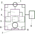
FIG. 1 is a schematic diagram showing the connection of the components of the autonomous navigation robot of the present invention;
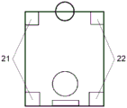
FIG. 2 is a schematic view of a turn signal.
The reference numbers are in sequence: the system comprises a laser radar 1, a steering lamp 2, a left steering lamp 21, a right steering lamp 22, a main controller 3, an IMU4, a motion control module 5, a light control module 6, a deceleration or reversing light 7, a working state light 8 and a power supply 9.
Detailed Description
In order to make the technical means, the creation characteristics, the achievement purposes and the functions of the invention clearer and easier to understand, the invention is further explained by combining the drawings and the detailed implementation mode:
as shown in fig. 1, an autonomous navigation robot includes a robot body; the robot body is provided with a control module, the control module comprises a main controller 3, a motion control module 5, a light control module 6 and an IMU4, and the main controller 3 is respectively connected with the motion control module 5, the light control module 6 and the IMU 4; still be provided with a plurality of state lamps and all be connected with light control module 6 on the robot body, still install laser radar 1 on one side of the robot body.
The main controller 3 is a data processing and decision center of the robot; the IMU4 is an inertial navigation unit and can calculate the current pose of the robot; the laser radar 1 can detect obstacles around the robot and the distance between the robot and the obstacles; the motion control module 5 can control the rotating speed of the motor through a driver; the light control module 6 can control the brightness of each lamp, and the color and brightness of the status lamp can obviously judge the brightness or twinkling when the outdoor weather is clear.
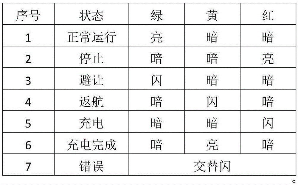
The working state lamp 8 represents the current state of the robot through different lamp light colors and flickering combinations, and the state is shown in the following table:
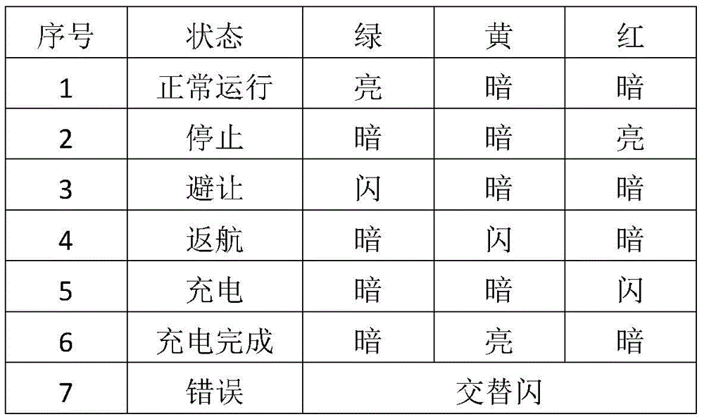
the unique working state lamp 8 is designed, different working states are represented by changing the brightness, the flicker and the color of the lamp, the operation is convenient and visual, the component utilization rate is improved, the component structure is simplified, and the working efficiency is also improved.
The invention also provides an interaction method of the autonomous navigation robot, which comprises the following steps:
detection step 1): the main controller 3 calculates a self safe area according to the motion path and the real-time speed of the robot, the laser radar 1 emits laser beams for detection, if no obstacle exists in the area, the robot does not decelerate or stops avoiding, and if an obstacle is detected in the robot safe area, the laser radar 1 transmits signals to the main controller 3;
moving state light change state 3): the light control module 6 analyzes the state of each motion state light according to the steering information of the main controller 3, and then controls the state of the motion state light.
The main controller 3 is specifically configured to: combining the motion state and the position information of the robot, the main controller 3 plans the robot path again to generate new motion control instructions and steering information, the main controller 3 sends the motion control instructions to the motion control module 5 and the light control module 6, the motion control module 5 controls the motion of the robot, and the light control module 6 analyzes the state of each state lamp from the control instruction information and controls each state lamp to change the display state of the state lamp.
When the main controller 3 receives the angular velocity transformation of the IMU4 module course angle and the large negative acceleration on the course, the main controller 3 sends the steering information and the deceleration information to the light control module 6.
Further comprising the steps of operating the status light 8: when the robot body is in a working state, namely a normal running state, a stop state, an avoidance state, a return state, a charging completion state and an error state, the main controller 3 can send a signal to the light control module 6, and then the light control module 6 transmits the signal to the working state lamp 8.
The robot can calculate the safety area of the robot according to the path and the speed at that time, and as long as no obstacle exists in the area, the robot does not need to decelerate or stop avoiding. When the obstacle is in the robot safety area, the main controller 3 plans the robot path again to generate a new motion control instruction and steering information, the main controller sends the motion control instruction to the motion control module 5, the steering and deceleration information is sent to the light control module 6, the light control module 6 analyzes the state of each lamp according to the steering information, and then the state of the lamp is controlled.
Finally, the above embodiments are only for illustrating the technical solutions of the present invention and not for limiting, although the present invention has been described in detail with reference to the preferred embodiments, it should be understood by those skilled in the art that modifications or equivalent substitutions may be made to the technical solutions of the present invention without departing from the spirit and scope of the technical solutions of the present invention, and all of them should be covered in the claims of the present invention.
Claims (7)
1. An autonomous navigation robot is characterized by comprising a robot body; the robot body is provided with a control module, the control module comprises a main controller, a motion control module, a light control module and an IMU, and the main controller is respectively connected with the motion control module, the light control module and the IMU; the robot body is also provided with a plurality of status lamps which are all connected with the light control module, and one side surface of the robot body is also provided with a laser radar;
wherein, laser radar is installed to the robot body one side that is located forward moving direction, the status light includes a operating condition lamp and five removal status lights, and the removal status light ring-shaped surrounds in the robot fuselage.
2. The autonomous navigation robot of claim 1, wherein four moving status lights are respectively located at the front left, front right, rear left and rear right ends of the robot body, the front left and rear left moving status lights are left turn lights, the front right and rear right moving status lights are right turn lights, and one moving status light is a deceleration or reversing light disposed at the back of the robot body.
3. The autonomous navigation robot of claim 2, wherein the operation status light represents the current status of the robot by a combination of different lighting colors and blinking, the status being as shown in the following table:
4. an autonomous navigation robot interaction method is characterized by comprising the following steps:
detection step 1): the main controller calculates a self safe area according to the motion path and the real-time speed of the robot, the laser radar emits laser beams for detection, if no obstacle exists in the area, the robot does not decelerate or stop avoiding, and if an obstacle is detected in the robot safe area, the laser radar transmits a signal to the main controller;
the master controller issues instruction 2): when the obstacle is in the robot safety area, the main controller replans the robot path, generates a new motion control instruction and steering information, sends the motion control instruction to the motion control module, and sends the steering information and deceleration information to the light control module;
moving state light change state 3): the light control module analyzes the state of each motion state lamp according to the steering information of the main controller and then controls the state of the motion state lamp.
5. The autonomous navigation robot interaction method of claim 4, wherein the master controller is specifically configured to: the main controller replans the robot path by combining the motion state and the position information of the robot to generate a new motion control instruction and steering information, the main controller sends the motion control instruction to the motion control module and the light control module, the motion control module controls the motion of the robot, and the light control module analyzes the state of each state lamp from the control instruction information and controls each state lamp to change the displayed state.
6. The method as claimed in claim 5, wherein when the main controller receives the IMU module course angle angular velocity transformation and the large negative acceleration, the main controller sends the turning information and the deceleration information to the light control module.
7. The autonomous navigational robot interaction method of claim 4, further comprising the steps of: when the robot body is in a working state, namely a normal running state, a stopping state, an avoiding state, a returning state, a charging completion state and an error state, the main controller can send a signal to the light control module, and then the light control module transmits the signal to the working state lamp.
Priority Applications (1)
| Application Number | Priority Date | Filing Date | Title |
|---|---|---|---|
| CN202010203597.5A CN111208837A (en) | 2020-03-20 | 2020-03-20 | Autonomous navigation robot and autonomous navigation robot interaction method |
Applications Claiming Priority (1)
| Application Number | Priority Date | Filing Date | Title |
|---|---|---|---|
| CN202010203597.5A CN111208837A (en) | 2020-03-20 | 2020-03-20 | Autonomous navigation robot and autonomous navigation robot interaction method |
Publications (1)
| Publication Number | Publication Date |
|---|---|
| CN111208837A true CN111208837A (en) | 2020-05-29 |
Family
ID=70789957
Family Applications (1)
| Application Number | Title | Priority Date | Filing Date |
|---|---|---|---|
| CN202010203597.5A Pending CN111208837A (en) | 2020-03-20 | 2020-03-20 | Autonomous navigation robot and autonomous navigation robot interaction method |
Country Status (1)
| Country | Link |
|---|---|
| CN (1) | CN111208837A (en) |
Cited By (2)
| Publication number | Priority date | Publication date | Assignee | Title |
|---|---|---|---|---|
| CN114347061A (en) * | 2022-01-24 | 2022-04-15 | 美的集团(上海)有限公司 | Atmosphere lamp setting method and setting device for robot and robot |
| JPWO2023037773A1 (en) * | 2021-09-09 | 2023-03-16 |
Citations (10)
| Publication number | Priority date | Publication date | Assignee | Title |
|---|---|---|---|---|
| CN105607637A (en) * | 2016-01-25 | 2016-05-25 | 重庆德新机器人检测中心有限公司 | Unmanned vehicle autopilot system |
| CN106886219A (en) * | 2017-03-06 | 2017-06-23 | 上海悦合自动化技术有限公司 | Robot automated navigation system |
| CN107562048A (en) * | 2017-08-08 | 2018-01-09 | 浙江工业大学 | Dynamic obstacle avoidance control method based on laser radar |
| CN206855451U (en) * | 2017-03-29 | 2018-01-09 | 北京智能佳科技有限公司 | A kind of non-humanoid service robot |
| CN207415334U (en) * | 2017-09-30 | 2018-05-29 | 斯坦德机器人(深圳)有限公司 | A kind of outdoor robot |
| CN108608443A (en) * | 2018-05-10 | 2018-10-02 | 吉林省允升科技有限公司 | A kind of intellect service robot control system |
| US20190088148A1 (en) * | 2018-07-20 | 2019-03-21 | Cybernet Systems Corp. | Autonomous transportation system and methods |
| CN209022058U (en) * | 2018-11-07 | 2019-06-25 | 深圳无境智能机器人有限公司 | A kind of outdoor crusing robot system |
| CN110716549A (en) * | 2019-11-04 | 2020-01-21 | 中国船舶重工集团公司第七一六研究所 | Autonomous navigation robot system for map-free area patrol and navigation method thereof |
| CN212083993U (en) * | 2020-03-20 | 2020-12-04 | 重庆德新机器人检测中心有限公司 | Autonomous navigation robot |
-
2020
- 2020-03-20 CN CN202010203597.5A patent/CN111208837A/en active Pending
Patent Citations (10)
| Publication number | Priority date | Publication date | Assignee | Title |
|---|---|---|---|---|
| CN105607637A (en) * | 2016-01-25 | 2016-05-25 | 重庆德新机器人检测中心有限公司 | Unmanned vehicle autopilot system |
| CN106886219A (en) * | 2017-03-06 | 2017-06-23 | 上海悦合自动化技术有限公司 | Robot automated navigation system |
| CN206855451U (en) * | 2017-03-29 | 2018-01-09 | 北京智能佳科技有限公司 | A kind of non-humanoid service robot |
| CN107562048A (en) * | 2017-08-08 | 2018-01-09 | 浙江工业大学 | Dynamic obstacle avoidance control method based on laser radar |
| CN207415334U (en) * | 2017-09-30 | 2018-05-29 | 斯坦德机器人(深圳)有限公司 | A kind of outdoor robot |
| CN108608443A (en) * | 2018-05-10 | 2018-10-02 | 吉林省允升科技有限公司 | A kind of intellect service robot control system |
| US20190088148A1 (en) * | 2018-07-20 | 2019-03-21 | Cybernet Systems Corp. | Autonomous transportation system and methods |
| CN209022058U (en) * | 2018-11-07 | 2019-06-25 | 深圳无境智能机器人有限公司 | A kind of outdoor crusing robot system |
| CN110716549A (en) * | 2019-11-04 | 2020-01-21 | 中国船舶重工集团公司第七一六研究所 | Autonomous navigation robot system for map-free area patrol and navigation method thereof |
| CN212083993U (en) * | 2020-03-20 | 2020-12-04 | 重庆德新机器人检测中心有限公司 | Autonomous navigation robot |
Cited By (3)
| Publication number | Priority date | Publication date | Assignee | Title |
|---|---|---|---|---|
| JPWO2023037773A1 (en) * | 2021-09-09 | 2023-03-16 | ||
| JP7652270B2 (en) | 2021-09-09 | 2025-03-27 | 村田機械株式会社 | Vehicle system and vehicle |
| CN114347061A (en) * | 2022-01-24 | 2022-04-15 | 美的集团(上海)有限公司 | Atmosphere lamp setting method and setting device for robot and robot |
Similar Documents
| Publication | Publication Date | Title |
|---|---|---|
| US10384596B2 (en) | System for detecting surrounding conditions of moving body | |
| CN206532138U (en) | A kind of unmanned vehicle automatic Pilot intelligence system | |
| CN110197036B (en) | Intelligent driving evaluation system and evaluation method | |
| US11648872B2 (en) | Display device and display method for display device | |
| US20240249651A1 (en) | Visual communication system | |
| CN109070891A (en) | The intention communication of automatic driving vehicle | |
| US12428009B2 (en) | Notification device | |
| CN111208837A (en) | Autonomous navigation robot and autonomous navigation robot interaction method | |
| CN109343529A (en) | Control method for vehicle and device | |
| CN217705637U (en) | Intelligent car lamp control system based on multiple sensors | |
| US20250303962A1 (en) | Notification method, notification system, and vehicle | |
| CN212083993U (en) | Autonomous navigation robot | |
| Zhang et al. | An adaptive driving beam system with integrated automatic lamp control function | |
| US20230294598A1 (en) | Annunciation method, annunciation device, and storage medium | |
| Jia et al. | Automatic traffic safety alert system for pedestrians | |
| CN224104199U (en) | A type of two-wheeled vehicle | |
| CN221642590U (en) | A road laser projection safety reminder device for cycling | |
| CN110182129A (en) | Vehicle illumination control method, device, control device and the vehicles | |
| KR20250027865A (en) | Status Information Providing Device for Moving Objects | |
| CN120840603A (en) | A safety detection and driving warning system based on vehicle lights | |
| CN114347904A (en) | Vehicle driving range prompt warning and display system, method, medium and equipment | |
| WO2025205074A1 (en) | Display device | |
| JPH04114603U (en) | Unmanned vehicle travel control device in a multiple unmanned vehicle system |
Legal Events
| Date | Code | Title | Description |
|---|---|---|---|
| PB01 | Publication | ||
| PB01 | Publication | ||
| SE01 | Entry into force of request for substantive examination | ||
| SE01 | Entry into force of request for substantive examination | ||
| RJ01 | Rejection of invention patent application after publication |
Application publication date: 20200529 |
|
| RJ01 | Rejection of invention patent application after publication |