Detailed Description
The present invention generally relates to a nozzle for injecting a mixture of reductant and air into an exhaust stream. Wherever possible, the same reference numbers will be used throughout the drawings to refer to the same or like features. In the drawings, the left-most digit(s) of a reference number identifies the drawing in which the reference number first appears.
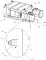
FIG. 1 illustrates an example exhaust system 100. For the purposes of the present invention, the exhaust system 100 is depicted and described as being used with a diesel-fueled internal combustion engine. However, it is contemplated that exhaust system 100 may embody any exhaust system that may be used with any other type of internal combustion engine, such as a gasoline or gas fueled power engine, or an engine fueled by compressed or liquefied natural gas, propane, or methane.
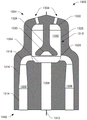
The exemplary exhaust system 100 includes components that condition the byproducts of combustion. For example, the exhaust system 100 may include a treatment system 102 that removes regulated constituents from the exhaust 104 and/or acts on the regulated constituents. Exhaust 104 may be generated by an engine (not shown) and may enter exhaust system 100 via an exhaust inlet 106 of an exhaust pipe 108. Upon entering the exhaust system 100, the exhaust gas 104 may pass within the exhaust pipe 108 in the direction of arrow 110 and may exit the exhaust system 100 via an exhaust outlet 112.
Within the exhaust pipe 108, the exhaust gas 104 may undergo one or more treatment processes. For example, the treatment process may include converting NO to NO2. A portion of the processing system 102 is shown in greater detail in the enlarged view 114. Among other components, the treatment system 102 may include a nozzle 116, the nozzle 116 receiving the reductant and air, facilitating mixing of the reductant and air to atomize the reductant, and dispersing the reductant and air solution into the exhaust 104. In some examples, the reductant received by the nozzle 116 may include a gaseous or liquid reductant. For example, the reducing agent may be ammonia gas, liquefied anhydrous ammonia, ammonium carbonate, ammoniaA salt solution, or a hydrocarbon, such as diesel fuel, that can be injected or otherwise propelled through the nozzle 116 and into the exhaust 104.
The example treatment system 102 may also include a supply line 118, and the supply line 118 may be configured to supply the nozzle 116 with a fluid and/or gas for treating the exhaust gas 104. In some examples, supply line 118 may include a plurality of different supply lines (e.g., supply line 118 may include a dual tube), such as a compressed air line, and a reductant supply line that may be separate from the compressed air line. In such an example, a compressed air line may supply compressed air to the nozzle 116 and a reductant supply line may supply reductant to the nozzle 116. The treatment system 102 may also include a compressor (not shown) configured to supply compressed air via the supply line 118, and one or more reservoirs and pumps (not shown) configured to supply reductant via the supply line 118. In some embodiments, the amount of compressed air and/or the amount of reductant supplied may depend on the flow rate of the exhaust gas 104, the operating state of the engine (e.g., rpm), the temperature of the exhaust gas 104, NO in the exhaust gas 104xAnd/or one or more other operating conditions of the treatment system 102 or the engine. For example, as the flow rate of the exhaust gas 104 decreases, a controller or other control component (not shown) operatively connected to the pump may control the pump to correspondingly decrease the amount of reductant and/or air supplied to the nozzle 116 (and thus introduced into the exhaust gas 104). Alternatively, the controller or other control component may increase the amount of reductant and/or air supplied to the nozzle 116 as the flow rate of the exhaust gas 104 increases.
The nozzle 116 may be fluidly connected to the supply line 118 at a first end 120 of the nozzle 116 via one or more fittings or couplings configured to receive air and/or reductant via the supply line 118. Additionally, the nozzle 116 may be disposed within the exhaust pipe 108 at a fixed location, and the supply line 118 may support the nozzle 116 at any location within the internal passage formed by the exhaust pipe 108. In some examples, the nozzle 116 may be disposed substantially centrally within the exhaust pipe 108. In other examples, the nozzle 116 may be disposed adjacent and/or proximate to a wall of the exhaust pipe 108 (e.g., adjacent and/or proximate to a wall forming an internal passage of the exhaust pipe 108).
As discussed in detail herein, the nozzle 116 may be formed and/or otherwise configured to direct the supplied reductant to impinge on and/or impinge on an impingement surface within the nozzle 116. This process can cause the reducing agent to break up into fine particles or droplets. The nozzle 116 may also be formed and/or configured to direct the supplied air to mix with the reductant particles, which may further facilitate atomization of the reductant. In such an example, the air and reductant may mix within the nozzle 116 to form the reductant solution. The nozzle 116 may also be configured to disperse and/or otherwise direct the reductant solution into the exhaust gas 104 through one or more outlets disposed at the second end 122 of the nozzle 116. In some embodiments, the outlet at the second end 122 of the nozzle 116 (or the passage supplying the outlet) may be helical to further enhance mixing of the air and reductant, impart a circular flow of reductant solution exiting the nozzle 116, or alter the plume size of reductant solution within the exhaust gas 104. Additionally, the second end 122 of the nozzle 116 may be oriented such that the reductant solution may be dispersed substantially in-line with the flow of the exhaust gas 104 within the exhaust pipe 108 and/or substantially in the same direction as the flow of the exhaust gas 104 within the exhaust pipe 108. In some examples, the reductant solution may be dispersed in a substantially conical plume and have a swirling motion about the longitudinal axis of the nozzle 116. Thus, when the reductant solution is dispersed into the exhaust gas 104, the reductant solution may react with NO in the exhaust gas 104x(e.g., NO and/or NO)2) Reacting to form water (H)2O) and elemental nitrogen (N)2)。
Although only one nozzle 116 is shown coupled to the supply line 118, in some embodiments, the exhaust system 100 and/or the treatment system 102 may include more than one nozzle 116. Further, the exhaust system 100 and/or the treatment system 102 may include more than one supply line 118, and the exhaust system 100 may include any number of supply lines 118 and/or one or more nozzles 116 positioned thereinThe exhaust pipe 108. Additionally, in some examples, one or more nozzles 116 may inject the reductant solution into the exhaust gas 104 along a substantially straight section of the exhaust system 100 (e.g., within a substantially straight section of the exhaust pipe 108) to improve mixing of the reductant solution with the exhaust gas 104 and/or increase the reductant solution with NO in the exhaust gas 104xThe level of reaction therebetween.
In some embodiments, the nozzle 116 may be located downstream of a Selective Catalytic Reduction (SCR) system within the exhaust system 100 and/or other treatment systems. Further, exhaust system 100 and/or treatment system 102 may include one or more oxidation catalysts, mixing features, particulate filters (e.g., Diesel Particulate Filters (DPFs)), SCR substrates, ammonia reduction catalysts, and catalysts configured to further enhance reduction of NOXOther means of efficiency.
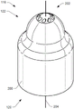
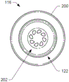
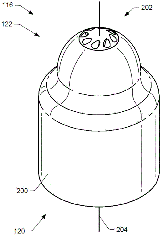
Fig. 2 shows a top perspective view of the nozzle 116. As shown in fig. 2, in some examples, the first end 120 of the nozzle 116 may be cylindrical while the second end 122 of the nozzle 116 is conical. In other examples, the first end 120 of the nozzle 116 may be cylindrical while the second end 122 of the nozzle 116 may be dome-shaped. Additionally, an outer surface 200 of the nozzle 116 may extend between the first end 120 and the second end 122. The outer surface 200 of the nozzle 116 may be a continuous smooth surface with rounded corners and edges to potentially reduce drag and/or turbulence as the exhaust gas 104 passes through the nozzle 116.
The second end 122 of the nozzle 116 may include one or more injection passage outlets 202 for dispensing a reductant solution into the exhaust gas 104. The spray channel outlet 202 may be formed on the outer surface 200 of the nozzle 116. In some embodiments, the spray channel outlets 202 may be evenly distributed about the longitudinal axis 204 of the nozzle 116. As will be described below, the nozzle 116 may include corresponding flow channels and/or other channels (shown in fig. 11 and 12) to direct the reductant solution from the internal cavity of the nozzle 116 to one or more injection channel outlets 202.
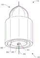
Fig. 3 shows a bottom perspective view of the nozzle 116. The first end 120 of the nozzle 116 may include an air passage inlet 300 and a reductant passage inlet 302, the air passage inlet 300 being configured to receive air from the supply line 118, the reductant passage inlet 302 being separate from the air passage inlet 300 and configured to receive reductant from the supply line 118. As shown, the air passage inlet 300 and the reductant passage inlet 302 may be substantially annular fluid inlets defined by the nozzle 116. For example, the air passage inlet 300 may extend substantially around the reductant passage inlet 302 and may resemble a ring or ring around the reductant passage inlet 302 (e.g., concentric with the reductant passage inlet 302). The reductant passage inlet 302 may be substantially centrally located within the nozzle 116 and may be substantially concentric with the longitudinal axis 204 of the nozzle 116.
In such examples, the air channel inlet 300 may be fluidly connected to an air channel 304 defined by the nozzle 116. The air channel inlet 300 may be configured to supply air received from the supply line 118 to the air channel 304. Further, reductant passage inlet 302 may be fluidly connected to a reductant passage 306 defined by nozzle 116. In these examples, the reductant passage inlet 302 may be configured to supply the reductant passage 306 with reductant received from the supply line 118. In an exemplary embodiment, air passage 304 and/or reductant passage 306 may extend from first end 120 of nozzle 116 toward second end 122 of nozzle 116 to direct air and reductant, respectively, into an internal cavity of nozzle 116. Within the internal cavity, the air and reductant may mix to form a reductant solution, and the reductant solution may be directed to exit the second end 122 of the nozzle 116 through one or more injection passage outlets 202. Additionally, the first end 120 of the nozzle 116 may be configured to couple the nozzle 116 to the supply line 118 via threads included in the first end 120, via a snap fit, via a compression fit, and/or via one or more of the aforementioned couplers.
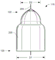
Fig. 4 shows a side view of the nozzle 116. As shown, the nozzle 116 may be substantially symmetrical about a longitudinal axis 204 of the nozzle 116. As described above, the first end 120 of the nozzle 116 may be substantially cylindrical, and the second end 122 of the nozzle 116 may be substantially conical, substantially frustoconical, substantially dome-shaped, and/or any other configuration. The size (e.g., width or diameter) of the nozzle 116 may decrease in size from a first end 120 of the nozzle 116 to a second end 122 of the nozzle 116. For example, the first end 120 of the nozzle 116 may have a first diameter or cross-sectional distance (D1) that may be greater than a second diameter or cross-sectional distance (D2) at the second end 122 of the nozzle 116. The outer surface 200 of the nozzle 116 may smoothly transition between the first diameter D1 and the second diameter D2 (or vice versa) to form a continuous surface.
Fig. 5 shows a top view of the nozzle 116. The second end 122 of the nozzle 116 may include an injection passage outlet 202 for dispensing a reductant solution into the exhaust gas 104. The injection channel outlet 202 may include a variety of cross-sectional shapes or sizes. For example, the spray channel outlets 202 may be generally conical, generally circular, generally trapezoidal, generally square, generally rectangular, generally oval, and/or any other shape. In some exemplary embodiments, the injection passage outlet 202 or the passage supplying reductant solution to the injection passage outlet 202 may be helical and/or face in an outward direction away from the outer surface 200 at the second end 122 of the nozzle 116. That is, in some examples, the injection passage outlets 202 and/or the injection passages may be angled and/or otherwise configured to direct the reductant solution away from the longitudinal axis 204 (fig. 2) of the nozzle 116. Such a configuration may facilitate dispersing the reductant solution within the exhaust gas 104 (FIG. 1), mixing the air and reductant within the nozzle 116, and/or adjusting the size of the plume dispersed by the nozzle 116. Additionally, the helical nature of the passages may cause the reductant solution to exit the nozzle 116 in a swirling motion about the longitudinal axis 204 of the nozzle 116.
In some examples, the spray channel outlets 202 may be substantially evenly distributed and/or radially spaced about the second end 122 and about the longitudinal axis 204 of the nozzle 116. Additionally, the individual injection passage outlets 202 may be diametrically opposed to one another such that the reductant solution may be evenly dispersed into the exhaust gas 104. Further, although eight jet channel outlets 202 are shown in fig. 5, the nozzle 116 may include more or less than eight jet channel outlets 202. For example, the nozzle 116 may include 12 jet channel outlets 202 or 4 jet channel outlets 202.
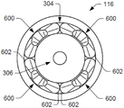
Fig. 6 shows a bottom view of the nozzle 116. As shown in fig. 6, in some examples, the air channel 304 may be bifurcated, branched, or otherwise divided into a plurality of air passages 600, such as four air passages 600, defined by the nozzle 116. That is, although shown in FIG. 2 as including a generally cylindrical shaped air passage 304, the air passage 304 may extend a predetermined length into the nozzle 116 in the direction of the longitudinal axis 204 and may branch into the respective air passage 600 defined by the nozzle 116. Each air passage 600 may include a respective air passage inlet 602 defined by the nozzle 116 and configured to receive air from the air channel 304. In some exemplary embodiments, the air passages 600 and the air passage inlets 602 may be evenly distributed about the longitudinal axis 204 of the nozzle 116 such that the air passages 600 may be substantially diametrically opposed to each other.
As shown in fig. 6, one or more air passages 600 may include a cross-sectional area at an air passage inlet 602 that may resemble a substantially curved and/or substantially oval shape. One or more of the air passages 600 may taper (e.g., may decrease in diameter) to a respective air passage outlet as the air passages 600 proceed radially inward toward the interior cavity in a direction toward the second end 122 of the nozzle 116. Additionally, the air passage 600 may be curved, tapered, chamfered, frustoconical, and/or any combination thereof.
Air passage 600 may be configured to direct air received via air passage inlet 602 toward an interior cavity of nozzle 116, where the air may be directed toward the reductant. Additionally, because the cross-sectional area of the air passages 600 decreases in size as the air passages 600 progress toward the inner chamber 600, the velocity of air passing through the respective air passages 600 may increase as the air approaches the second end 122 of the nozzle 116. Thus, when injected into the lumen, the air may decompose the reducing agent at an increased rate to increase atomization of the reducing agent. In some embodiments, each air passage 600 may include a similar size and shape to each other such that each air passage 600 receives a substantially equal amount of air from the air channel 304. Furthermore, by having a similar size and/or shape, the air supplied by each air passage 600 may be uniformly mixed with the reductant, potentially resulting in substantially uniform atomization within the interior cavity of the nozzle 116. Further, although an exemplary air passage 304 is shown in FIG. 6 as branching into four air passages 600, the nozzle 116 may include more or less than four air passages 600. For example, in some examples, the nozzle 116 may include more or less than twelve air passages 600.
FIG. 7 illustrates a cross-sectional view of the nozzle 116 taken along the X-Y plane and viewed at an off-perpendicular angle relative to the X-Y plane. As shown in fig. 7, the nozzle 116 may include an inner cavity 700 disposed inside the outer surface 200 of the nozzle 116. As shown, the internal cavity 700 may be disposed between the first end 120 and the second end 122 of the nozzle 116, but in some cases may be disposed closer to the second end 122 than the first end 120 of the nozzle 116.
The internal cavity 700 may be formed by the nozzle 116 and may be defined by a bottom end 702, a top end 704, and a sidewall 706 formed by the nozzle 116. In such an example, the sidewall 706 can extend from the bottom end 702 to the top end 704 of the internal cavity 700. In some examples, the lumen 700 may include a structure 708 and a chamber 710. For example, the structure 708 may be substantially centrally located within the internal cavity 700, and the structure 708 may be substantially centrally aligned with the longitudinal axis 204 of the nozzle 116. In some cases, the structure 708 may extend from the bottom end 702 of the lumen 700 toward the top end 704 of the lumen 700. However, in some embodiments, the structures 708 may extend from the top 704 or the sidewalls 706 of the lumen 700.
As shown in fig. 7, in some examples, the structure 708 may include a first side having an impact surface 712 and a second side opposite the first side having a substantially conical top 714. In some examples, impact surface 712 may be substantially concave and may include a substantially conical surface, a substantially hemispherical surface, and/or combinations thereof. In some examples, the impingement surface 712 may be oriented at an acute included angle equal to about 15 degrees, about 30 degrees, about 45 degrees, and/or any other value with respect to an axis or plane extending perpendicular to the longitudinal axis 204 of the nozzle 116.
The structure 708 may also include one or more posts, or legs 716 extending from a first side of the structure 708 adjacent the impact surface 712. Legs 716 may be above reductant passage 306 or offset relative to reductant passage 306 or support impact surface 712 of structure 708. For example, the legs 716 may couple the structure 708 to the bottom end 702, the top end 704, and/or the sidewalls 706 to support the impact surface 712 at any desired distance from the bottom end 702 of the internal cavity 700 or away from the reductant passage outlet 718. In some embodiments, structure 708 can include four legs 716 substantially equally spaced (i.e., spaced approximately 90 degrees apart) around reductant passage 306. However, in some embodiments, the structure 708 may include more or less than four legs 712. For example, the structure 708 may include three legs 716. Additionally, a gap or space may be provided between adjacent legs 716.
In some exemplary embodiments, a centerline of reductant passage 306 may be aligned with a center point (or centerline) of impingement surface 712 of structure 708. In such examples, longitudinal axis 204 of nozzle 116 may pass substantially centrally through impingement surface 712 and through reductant passage 306. Additionally, in some embodiments, impingement surface 712 may include a similar width as reductant passage 306. However, in some embodiments, the width of impingement surface 712 may be greater than the width of reductant passage 306 to account for any expansion of reductant exiting reductant outlet 718.
As described above, the nozzle 116 may include one or more air passages 600 that terminate at an outlet within the inner cavity 700. For example, each air passage 600 may include a respective air passage inlet 602 and a respective air channel outlet 720 that disperses air into the interior cavity 700. In some embodiments, the air passage 600 may terminate at the sidewall 706 of the inner cavity 700 and form an air passage outlet 720 that discharges air into the inner cavity 700.
In some embodiments, air passage outlet 720 may be oriented substantially perpendicular to reductant passage 306 and/or reductant passage outlet 718. In other words, the reductant may enter the internal cavity 700 substantially axially and along the longitudinal axis 204 of the nozzle 116, while the air enters the internal cavity 700 radially or substantially perpendicular to the longitudinal axis 204 of the nozzle 116. Additionally, the air passage outlets 720 may be substantially equally spaced around the perimeter of the inner cavity 700.
The top end 704 of the internal cavity 700 may converge (e.g., have a smaller diameter than the bottom end 702) to direct and accelerate the reductant solution to the injection passage outlet 202. That is, the apex 704 may converge toward the longitudinal axis 204 of the nozzle 116. As discussed in detail herein, the channels may direct the reductant solution from the chamber 710 to the injection channel outlet 202.
This expansion may minimize or eliminate clogging of the injection passage outlet 202.
As described above, legs 716 may support impact surface 712 from bottom end 702 of internal cavity 700 to allow reductant to be dispersed from below structure 708. Further, where structure 708 includes more than one leg, a gap may separate adjacent legs 716. In some embodiments, the air passage outlets 720 may be configured and oriented to disperse air toward gaps disposed between adjacent legs 716. In some embodiments, each air passage outlet 720 may be disposed opposite and/or oriented toward a respective gap between the legs 716. As such, air passage outlet 720 may be positioned and/or oriented to inject air into internal cavity 700 at a location where reductant exits from below structure 708. In other words, the gaps between adjacent legs 716 may allow the reductant to disperse radially toward sidewall 706 where it may mix with air.
The shape of legs 716 and/or the location of legs 716 within inner cavity 700 may minimize interference with the reductant as it passes from reductant passage 306 toward sidewalls 706. For example, legs 716 may include curved outer surfaces, thin profiles, and/or cross-sections. Additionally, leg 716 may include external features that may introduce swirling motion into the atomized reductant.
Additionally, the nozzle 116 may include more than four air passages 600 and associated air passage outlets 720. Increasing the number of air passages 600 may increase the amount of air injected into the internal cavity 700, which may result in increased atomization of the reductant. The number of air passages 600 may depend on the operating environment of the nozzle 116. For example, in applications where the flow rate or volume of the exhaust gas 104 is high, the inclusion of more air passages 600 may increase atomization of the reductant and/or compensate for the increased reductant flow rate.
Fig. 8 shows a cross-sectional view of the nozzle 116 along the X-Y plane and perpendicular to the X-Y plane. Fig. 8 illustrates that the bottom end 702 or a first portion of the lumen 700 can be cylindrical, while the top end 704 can include a smaller cross-sectional diameter relative to the bottom end 702 and can converge into a conical shape. Accordingly, the sidewall 706 may taper inwardly from the bottom end 702 to the top end 704, or may taper as the inner chamber 700 progresses radially inwardly from the first end 120 of the nozzle 116 to the second end 122 of the nozzle 116. The tapering of the inner cavity 700 may impart a swirling motion to the reductant solution to further atomize the reductant.
In such examples, the air passage 304 may extend substantially parallel to the longitudinal axis 204 of the nozzle 116 and may branch into an air passage 600 (discussed in more detail in fig. 10). The air channel 304 may be configured to receive air via the supply line 118, as indicated by arrow 800. Reductant passage 306 may supply reductant into internal cavity 700. The reductant passage 718 may be centrally located within the nozzle 116 and may be disposed between the reductant inlet 302 and the reductant passage outlet 718. As shown, reductant passage 306 may be generally cylindrical and may have a generally constant diameter. The reductant may be supplied along the longitudinal axis 204 of the nozzle 116, as indicated by arrow 802.
The air passage outlet 720 may be disposed at the sidewall 706 of the inner cavity 700 and may be oriented toward the center of the inner cavity 700 or toward the longitudinal axis 204 for mixing with the reductant. In some examples, the air passage outlet 720 or a cross-section of the air passage outlet 720 may include a variety of shapes, such as substantially circular, substantially oval, and/or any other shape. Fig. 8 further illustrates that the air passage outlet 720 and the leg 716 may be 90 degrees out of phase with each other. That is, by offsetting the air passage outlet 720 and the legs 716, or vice versa, air dispersed from the air passage 600 may be oriented toward the gaps 804 between adjacent legs 716.
The top end 704 of the internal cavity 700 may include a jet channel 806. As described above, injection passage 806 may be disposed between injection passage outlet 202 and internal cavity 700 to direct the reductant solution into exhaust gas 104. The injection channels 806 may receive the reductant solution at injection channel inlets 808 disposed at the top end 704 of the internal cavity 700.
Fig. 9 illustrates a cross-sectional view of the nozzle 116 showing the flow pattern of the reductant and air within the inner chamber 700. The cross-sectional view in fig. 9 shows through two air passages 600. As shown in FIG. 9, reductant passage 306 may direct reductant into internal cavity 700, where it may impinge on impingement surface 712 of structure 708, as indicated by arrow 900. The concave nature of impact surface 712 may help increase the atomization rate of the reductant. That is, the reductant may be broken down into relatively small particles by contacting, impinging, or otherwise impacting the concave impact surface 712. Due to the impingement surface 712 of the contact structure 708, the reductant may disperse radially away from the longitudinal axis 204 of the nozzle 116, toward the sidewall 706 of the internal cavity 700, and/or toward the air passage outlet 720, as indicated by arrows 902. As described above, and as shown in FIG. 9, impinging the impingement surface 712 disperses reductant radially from beneath the structure 708 via the gaps 804 between adjacent legs 716.
Air passage 600 may be disposed about reductant passage 306 and may direct air toward internal cavity 700 (or longitudinal axis 204), as indicated by arrow 904, and air passing through air passage 600 may exit air passage 600 into internal cavity 700 via air passage outlet 720, as indicated by arrow 906. Moreover, the concave geometry of impact surface 710 may substantially uniformly disperse the reductant into internal cavity 700 as the reductant impacts impact surface 712. This substantially uniform dispersion may allow the air to be uniformly mixed with the reductant. Because the air passage outlets 720 may be radially dispersed around the inner cavity 700, air may mix with the reductant from multiple directions. Thus, in a first instance, the reductant may impinge the impingement surface 712 and be dispersed radially outward toward the sidewall 706 of the inner cavity 700, and in a second instance, the air discharged from the air passage 600 may be mixed with the reductant.
The radial injection of air and mixing of the air and reductant may direct or introduce the reductant solution toward the lumen 700 and/or the top end 704 of the chamber 710. Within chamber 710, the air and reductant may mix to form a reductant solution. Additionally, the nature of the tapered top of the structure 708 may provide a desired vortex pattern or effect within the chamber 710. Swirling may further assist in mixing the reducing agent solution and/or further atomizing the reducing agent. Additionally, the chamber 710 may allow for expansion of the reductant solution and potentially reduce crystallization of the reductant solution. This expansion may minimize or eliminate clogging of the injection passage outlet 202.
Further, the air may exit the air passage outlet 720 at a plurality of angles or directions. For example, air may be injected in a direction toward the center of the inner cavity 700, or the air passage outlets 720 may be angled toward the sidewall 706 to induce a swirling motion within the inner cavity 700. Additionally, although fig. 9 illustrates that the air passage outlet 720 may be flush with and/or adjacent to the bottom end 702 of the internal cavity 700, in some examples, the air passage outlet 720 may be spaced above the bottom end 702 of the internal cavity 700. For example, the air passage outlet 720 may be centrally disposed between the bottom end 702 and the impingement surface 712 to radially mix with the reductant. Upon mixing with air, the reductant solution may funnel toward the chamber 710, as indicated by arrow 908. In chamber 710, the reductant solution may further mix and exit nozzle 116.
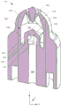
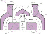
Fig. 10 shows a perspective view of the negative space 1000 corresponding to the nozzle 116. Negative space 1000 represents a void or void space associated with forming the nozzle 116 of the present invention in a three-dimensional ("3D") printing process or other manufacturing process. For example, the various components of the negative space 1000 shown in fig. 10 may represent the air channel 600, the internal cavity 700, and/or other flow channels/passages of the nozzle 116 formed during the example 3D printing process.
The negative space 1000 may be defined by a top 1002 and a bottom 1004, the top 1002 may correspond to the second end 122 of the nozzle 116, and the bottom 1004 may correspond to the first end 120 of the nozzle 116. Additionally, the negative space 1000 may include a jet channel void space 1006 corresponding to the channel 806 of the nozzle 116. The jet channel void spaces 1006 may include jet channel outlet void spaces 1008, which may correspond to the jet channel outlets 202, and jet channel inlet void spaces 1010, which may correspond to the jet channel inlets 808. In some exemplary embodiments, the jet channel void space 1006 may be helical or spiral about the longitudinal axis 204 of the nozzle 116. With this configuration, the spray channels 806 may spiral about the longitudinal axis 204 of the nozzle 116 as the spray channels 806 extend from the nozzle inlet 808 toward the spray channel outlet 202. In some embodiments, because the jet channel 806 spirals toward the second end 122 of the nozzle 116, the jet channel void space 1006 may converge toward the top 1002 of the void space 1000 as shown in fig. 10. In other words, at top 1002 of void space 1000, distance 1012 may be greater than distance 1014 extending from a center point of first jet channel inlet void space 1010 to a center point of second jet channel inlet void space 1010 adjacent to first jet channel inlet void space 1010 than from a center point of first jet channel outlet void space 1008 to a center point of second jet channel outlet void space 1008 adjacent to first jet channel outlet void space 1008.
Jet channel void space 1006 may also taper along the length of jet channel void space 1006 between jet channel inlet void space 1010 and jet channel outlet void space 1008. For example, injection channel void space 1006 may include a first cross-sectional area at injection channel inlet void space 1010 and a second cross-sectional area at injection channel outlet void space 1008, which may be less than the first cross-sectional area. Additionally, the cross-sectional shape of jet channel inlet void space 1010 may be different than the cross-sectional shape of jet channel outlet void space 1008. For example, jet channel inlet void space 1010 may comprise a trapezoidal shape, while jet channel outlet void space 1012 may comprise a circular shape.
Injection passage void spaces 1006 form injection passages 806 having a helical characteristic, which injection passages 806 may help impart fluid twist to the reductant solution and may further mix the reductant solution within exhaust pipe 108. In one embodiment, the swirling effect of the reductant solution may create a plume of reductant solution that is large enough to extend to, for example, the outer periphery of the exhaust pipe 108, and may facilitate conical injection of the reductant solution into the exhaust gas 104. In some embodiments, the angle at which the injection passage outlet 202 is oriented from the longitudinal axis 204 of the nozzle 116 may regulate the plume size or swirling motion of the reductant solution. For example, depending on the application of the nozzle 116, the injection channel void space 1006 and/or the injection channel outlet void space 1008 may be adjusted to produce a narrow plume or a wide plume. Additionally, the reduction in cross-sectional area of injection channels 806 may impart a velocity to the reductant solution as it passes from injection channel inlet 808 and out of injection channel outlet 202. The increased velocity may enhance mixing, atomization, and/or dispersion of the reducing agent solution.
Located at the bottom 1004 of the negative space 1000 may be an air channel void space 1016, which may correspond to the air channel 304. As described above, in some examples, the air channel 304 may branch into the air passages 600, including four air passages 600 that direct air into the internal cavity 700. Accordingly, negative space 1000 may include air passage void space 1018. For example, air passage void space 1018 may include a first portion 1020, a second portion 1022, and a third portion 1024.
Each air passage void space 1018 may branch off from the air channel void space 1016 to receive air. As air passage void space 1018 progresses from first portion 1020 toward second portion 1022, air passage void space 1018 may taper inward and decrease in cross-sectional area. As shown in fig. 10, the air passage void space 1018, and in particular the first portion 1020, may taper in multiple directions. As air passage void space 1018 approaches inner cavity 700 of nozzle 116, air passage void space 1018 may curve at second void space 1022. Wherein a third portion 1024 of the air passage void space 1018 may extend inwardly and toward the internal cavity 700.
In other words, reductant passage void space 1018 may form air passage 304 substantially parallel to longitudinal axis 204 of nozzle 116. Wherein air may pass from the air channel 304 to the air passage 600. The first portion 1020 may be substantially parallel to the longitudinal axis 204 and taper as the first portion 1020 progresses toward the second portion 1022 of the air passage void space 1018. The second portion 1022 of the air passage void space 1018 may be curved toward the longitudinal axis 204 of the nozzle 116. The third portion 1024 of the air passage void space 1018 may be substantially perpendicular to the longitudinal axis 204. Accordingly, in some exemplary embodiments, due to the configuration of air passage void space 1016 and air passage void space 1018, air passage 600 and/or air passage outlet 720 may be configured to direct air into internal cavity 700 in a direction substantially perpendicular to longitudinal axis 204 and/or substantially perpendicular to a flow direction of the injected reductant entering internal cavity 700 from reductant passage 306 (as shown in fig. 9). In such an example, the reductant passage outlet 718 and the air passage outlet 720 may be substantially perpendicular to each other.
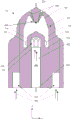
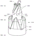
Fig. 11 shows a top view of the negative space 1000 of the nozzle 116. In fig. 11, each air passage void space 1018 is shown oriented toward the longitudinal axis 204 of the nozzle 116 to disperse air within the internal cavity 700 in different directions. More specifically, third portions 1024 of each air passage void space 1018 may be substantially diametrically opposed to each other such that air channeled by each air passage 600 is radially mixed with the reductant in different directions. Additionally, the dimensions of each air passage void space 1018 may be substantially similar to substantially evenly disperse air within inner cavity 700.
As also shown in fig. 11, the jet channel void space 1006 may follow a trajectory that rotates about the longitudinal axis 204 of the nozzle 116. Each jet channel 806 can include a respective jet channel void space 1006, the jet channel void space 1006 having a respective central longitudinal axis (not shown) extending from the jet channel inlet void space 1010 to the jet channel outlet void space 1008. Additionally, a diameter, perimeter, or cross-section of jet channel void space 1006 measured in a plane perpendicular to a longitudinal axis of jet channel void space 1006 may decrease from jet channel inlet void space 1010 to jet channel outlet void space 1008.
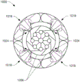
Fig. 12 shows a cross-sectional view of the negative space 1000 of the nozzle 116 taken along the X-Y plane and viewed from a perpendicular angle relative to the X-Y plane. As shown in fig. 12, the air channel void space 1016 may be configured as a substantially cylindrical aperture or annular ring. In some examples, the air channel void space 1016 may extend into the air passage void space 1018, and in particular, may extend into the first portion 1020 of the air passage void space 1018. Fig. 12 also shows that air passage void space 1018 may be oriented in a similar direction as reductant passage void space 1200, and that reductant passage void space 1200 may correspond to reductant passage 306 and may be substantially parallel to longitudinal axis 204 of nozzle 116. The air passage void space 1018 may be curved at or along the second portion 1022 and oriented inwardly toward the internal cavity 700 at the third portion 1024. The third portion 1024 of the air passage void space 1018 may extend substantially perpendicular to the longitudinal axis 204 of the nozzle 116 and may be oriented toward the inner cavity 700 of the nozzle 116. In one embodiment, the curve along the second portion 1022 may be 90 degrees such that the dispersed air from each air passage 600 may be oriented substantially perpendicular to the dispersed reductant exiting from the reductant passage 306. As shown at the top 1002 of the negative space 1000, the jet channel void space 1006 may follow a trajectory that spirals about the longitudinal axis 204 of the nozzle 116. In one embodiment, the injection channels 806 may be angled or oriented away from the longitudinal axis 204 of the nozzle 116.
FIG. 13 illustrates a cross-sectional view of another example nozzle 1300. In some embodiments, the nozzle 1300 may include similar features as the nozzle 116. The nozzle 1300 may include a first end 1302 and a second end 1304. FIG. 13 illustrates that the air passage 1306 and reductant passage 1308 may extend from the first end 1302 of the nozzle 1300. The air passage 1306 and reductant passage 1308 may receive air and reductant, respectively, from the supply line 118. The air passage 1306 and the reductant passage 1308 may direct air and reductant, respectively, to an internal cavity 1310 formed by the nozzle 1300.
The reductant passage 1308 may extend substantially parallel to a longitudinal axis 1312 of the nozzle 1300. In some examples, the air passage 1306 may include four portions. For example, the first portion 1314 of the air passage 1306 may be substantially parallel to the longitudinal axis 1312 of the nozzle 1300. The second portion 1316 of the air passage 1306 may be fluidly connected with the first portion 1312, may be substantially parallel to the longitudinal axis 1312 of the nozzle 1300 and may taper in multiple directions, thereby reducing the cross-sectional area of the air passage 1306. The third portion 1318 of the air passage 1306 may be fluidly connected with the second portion 1314 and curved toward the longitudinal axis 1312 of the nozzle 1300. A fourth portion 1318 of the air passage 1306 may be fluidly connected with the third portion 1316 and the inner cavity 1310 and may be substantially perpendicular to the longitudinal axis 1312 of the nozzle 1300.
The internal cavity 1310 may include a top end 1322 and a bottom end 1324 formed by the nozzle 1300. The sidewall 1326 may extend between the top end 1322 of the inner chamber 1310 and the bottom end 1324 of the inner chamber 1310 and may be formed by the nozzle 1300. In some examples, the nozzle 1300 may include a structure 1328 that may hang from a top end 1322 of the inner cavity 1310. In some examples, the structure 1308 may extend toward the bottom end 1324 of the inner cavity 1310. Additionally, the structure 1328 may include an impingement surface 1330 disposed above the bottom end 1324 of the inner cavity 1310 and opposite the reductant passage 1308.
Similar to the discussion above regarding the nozzle 116, the reductant may exit the reductant passage 1308 and impinge on the impingement surface 1330 of the structure 1318 to disperse the reductant radially into the inner cavity 1310. In this process, the impingement surface 1330 may atomize the reductant. That is, impingement surface 1330 may include similar features as impingement surface 712 to break up and atomize the reductant. For example, the impact surface 1330 may comprise a substantially concave surface. Air may contact the reductant by exiting air passage 1306. Wherein the reductant solution may advance toward the chamber 1332 for further mixing. The reductant solution may be dispersed through a spray outlet 1334 located at a top end 1322 of the inner chamber 1310. Similar to the spray outlets 202, the spray outlets 1334 and/or the passages feeding the spray outlets 1334 may follow a helical trajectory about the longitudinal axis 1312 of the nozzle 1300.
In some embodiments, by supporting the impingement surface 1330 with the structure 1328 shown in fig. 13, the reductant may be dispersed radially from the impingement surface 1330 without interference or with fewer interfaces. In such embodiments, when air is mixed with the reducing agent, this may result in increased atomization of the reducing agent. Additionally, the reductant may be substantially uniformly dispersed within the internal cavity 1310 to mix with air without hindrance, or with minimal hindrance.
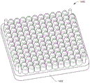
Fig. 14 illustrates an exemplary fabrication technique for fabricating the nozzle 116 and/or the nozzle 1300. In particular, fig. 14 shows a plurality of nozzles 1400 fabricated on a tray 1402 and using 3D printing techniques or other types of additive manufacturing (e.g., cast molding). In one embodiment, all of the components of the nozzle 116 and/or nozzle 1300 are fabricated using 3D printing techniques, and more or fewer nozzles than shown in fig. 14 may be fabricated in a single instance. Additionally, it is contemplated that one or more components of the above-described nozzle may alternatively be manufactured by other processes.
Industrial applicability
The exhaust system of the present disclosure may be used with any power system having a treatment system to reduce the amount of harmful emissions generated from an internal combustion engine. More specifically, the nozzle of the present invention may be applied to any liquid/gas mixing operation requiring effective, uniform and thorough mixing of reductant, air and exhaust gases. Although applicable to a range of treatment devices/systems, the disclosed treatment systems employing nozzles may be primarily beneficial when associated with SCR devices. The disclosed nozzle facilitates NO by efficiently atomizing reductant and dispersing a mixture of reductant and air in an exhaust stream of an enginexReduction of (2).
As described above, in some examples, air passage 304 and reductant passage 306 may receive air and reductant, respectively, from supply line 118. The reductant and air may mix within the internal cavity 700. The reductant may impinge on the impingement surface 712 to break up and atomize the urea. After this impact, the reducing agent is dispersed radially. The air may then impinge upon the dispersed reductant to further atomize the reductant. The air and reductant solution may be advanced into chamber 710 within lumen 700 for further mixing. The urea solution may then proceed toward a channel 1006 at the top end 704 of the lumen 700. When in useThe channel 1006 may rotate about the longitudinal axis 204 of the nozzle 116 as the channel 710 proceeds from the internal cavity 710 toward the injection channel outlet 202 at the second end 122 of the nozzle 116. The cross-sectional area of the injection channel 806 may also decrease. As a result, the distortion of passageway 1006 may further atomize the urea within passageway 1006. Also, the reduced cross-sectional area may impart velocity to the reductant solution flow. Thus, as the reductant solution exits the nozzle 116 through the injection passage outlet 202, the reductant solution may spin in a conical shape and further atomize the reductant. In addition, the swirling and conical nature of the urea plume may extend to the outer circumference of the exhaust pipe 108, thereby enabling NO within the exhaust 104xA decrease in increase of. As such, the processes performed within the processing system 102 may include, among other things, NO to NO2And/or particulate removal processes. Additionally, the nozzle 116 may increase mixing between the reductant and air and may reduce crystallization of the reductant within the nozzle 116. The nozzle 116 may also be fabricated from a single piece of material using 3D printing techniques to reduce manufacturing and/or assembly time.
It will be apparent to those skilled in the art that various modifications and variations can be made to the exhaust system of the present invention without departing from the scope of the invention. Other embodiments will be apparent to those skilled in the art from consideration of the specification and practice of the exhaust system disclosed herein. It is intended that the specification and examples be considered as exemplary only, with a true scope of the disclosure being indicated by the following claims and their equivalents.