CN111094465A - Coating composition, organic light emitting diode using the same, and preparation method thereof - Google Patents
Coating composition, organic light emitting diode using the same, and preparation method thereof Download PDFInfo
- Publication number
- CN111094465A CN111094465A CN201980004561.XA CN201980004561A CN111094465A CN 111094465 A CN111094465 A CN 111094465A CN 201980004561 A CN201980004561 A CN 201980004561A CN 111094465 A CN111094465 A CN 111094465A
- Authority
- CN
- China
- Prior art keywords
- group
- substituted
- unsubstituted
- coating composition
- formula
- Prior art date
- Legal status (The legal status is an assumption and is not a legal conclusion. Google has not performed a legal analysis and makes no representation as to the accuracy of the status listed.)
- Granted
Links
Images

Classifications
-
- C—CHEMISTRY; METALLURGY
- C08—ORGANIC MACROMOLECULAR COMPOUNDS; THEIR PREPARATION OR CHEMICAL WORKING-UP; COMPOSITIONS BASED THEREON
- C08F—MACROMOLECULAR COMPOUNDS OBTAINED BY REACTIONS ONLY INVOLVING CARBON-TO-CARBON UNSATURATED BONDS
- C08F212/00—Copolymers of compounds having one or more unsaturated aliphatic radicals, each having only one carbon-to-carbon double bond, and at least one being terminated by an aromatic carbocyclic ring
- C08F212/34—Monomers containing two or more unsaturated aliphatic radicals
-
- C—CHEMISTRY; METALLURGY
- C08—ORGANIC MACROMOLECULAR COMPOUNDS; THEIR PREPARATION OR CHEMICAL WORKING-UP; COMPOSITIONS BASED THEREON
- C08F—MACROMOLECULAR COMPOUNDS OBTAINED BY REACTIONS ONLY INVOLVING CARBON-TO-CARBON UNSATURATED BONDS
- C08F2/00—Processes of polymerisation
- C08F2/46—Polymerisation initiated by wave energy or particle radiation
- C08F2/48—Polymerisation initiated by wave energy or particle radiation by ultraviolet or visible light
-
- C—CHEMISTRY; METALLURGY
- C08—ORGANIC MACROMOLECULAR COMPOUNDS; THEIR PREPARATION OR CHEMICAL WORKING-UP; COMPOSITIONS BASED THEREON
- C08F—MACROMOLECULAR COMPOUNDS OBTAINED BY REACTIONS ONLY INVOLVING CARBON-TO-CARBON UNSATURATED BONDS
- C08F212/00—Copolymers of compounds having one or more unsaturated aliphatic radicals, each having only one carbon-to-carbon double bond, and at least one being terminated by an aromatic carbocyclic ring
- C08F212/02—Monomers containing only one unsaturated aliphatic radical
- C08F212/04—Monomers containing only one unsaturated aliphatic radical containing one ring
- C08F212/14—Monomers containing only one unsaturated aliphatic radical containing one ring substituted by heteroatoms or groups containing heteroatoms
- C08F212/26—Nitrogen
- C08F212/28—Amines
-
- C—CHEMISTRY; METALLURGY
- C09—DYES; PAINTS; POLISHES; NATURAL RESINS; ADHESIVES; COMPOSITIONS NOT OTHERWISE PROVIDED FOR; APPLICATIONS OF MATERIALS NOT OTHERWISE PROVIDED FOR
- C09D—COATING COMPOSITIONS, e.g. PAINTS, VARNISHES OR LACQUERS; FILLING PASTES; CHEMICAL PAINT OR INK REMOVERS; INKS; CORRECTING FLUIDS; WOODSTAINS; PASTES OR SOLIDS FOR COLOURING OR PRINTING; USE OF MATERIALS THEREFOR
- C09D4/00—Coating compositions, e.g. paints, varnishes or lacquers, based on organic non-macromolecular compounds having at least one polymerisable carbon-to-carbon unsaturated bond ; Coating compositions, based on monomers of macromolecular compounds of groups C09D183/00 - C09D183/16
- C09D4/06—Organic non-macromolecular compounds having at least one polymerisable carbon-to-carbon unsaturated bond in combination with a macromolecular compound other than an unsaturated polymer of groups C09D159/00 - C09D187/00
-
- H—ELECTRICITY
- H10—SEMICONDUCTOR DEVICES; ELECTRIC SOLID-STATE DEVICES NOT OTHERWISE PROVIDED FOR
- H10K—ORGANIC ELECTRIC SOLID-STATE DEVICES
- H10K50/00—Organic light-emitting devices
- H10K50/10—OLEDs or polymer light-emitting diodes [PLED]
- H10K50/14—Carrier transporting layers
- H10K50/15—Hole transporting layers
-
- H—ELECTRICITY
- H10—SEMICONDUCTOR DEVICES; ELECTRIC SOLID-STATE DEVICES NOT OTHERWISE PROVIDED FOR
- H10K—ORGANIC ELECTRIC SOLID-STATE DEVICES
- H10K50/00—Organic light-emitting devices
- H10K50/10—OLEDs or polymer light-emitting diodes [PLED]
- H10K50/17—Carrier injection layers
-
- H—ELECTRICITY
- H10—SEMICONDUCTOR DEVICES; ELECTRIC SOLID-STATE DEVICES NOT OTHERWISE PROVIDED FOR
- H10K—ORGANIC ELECTRIC SOLID-STATE DEVICES
- H10K85/00—Organic materials used in the body or electrodes of devices covered by this subclass
- H10K85/10—Organic polymers or oligomers
- H10K85/111—Organic polymers or oligomers comprising aromatic, heteroaromatic, or aryl chains, e.g. polyaniline, polyphenylene or polyphenylene vinylene
-
- H—ELECTRICITY
- H10—SEMICONDUCTOR DEVICES; ELECTRIC SOLID-STATE DEVICES NOT OTHERWISE PROVIDED FOR
- H10K—ORGANIC ELECTRIC SOLID-STATE DEVICES
- H10K85/00—Organic materials used in the body or electrodes of devices covered by this subclass
- H10K85/30—Coordination compounds
- H10K85/321—Metal complexes comprising a group IIIA element, e.g. Tris (8-hydroxyquinoline) gallium [Gaq3]
- H10K85/322—Metal complexes comprising a group IIIA element, e.g. Tris (8-hydroxyquinoline) gallium [Gaq3] comprising boron
-
- H—ELECTRICITY
- H10—SEMICONDUCTOR DEVICES; ELECTRIC SOLID-STATE DEVICES NOT OTHERWISE PROVIDED FOR
- H10K—ORGANIC ELECTRIC SOLID-STATE DEVICES
- H10K85/00—Organic materials used in the body or electrodes of devices covered by this subclass
- H10K85/60—Organic compounds having low molecular weight
- H10K85/615—Polycyclic condensed aromatic hydrocarbons, e.g. anthracene
-
- H—ELECTRICITY
- H10—SEMICONDUCTOR DEVICES; ELECTRIC SOLID-STATE DEVICES NOT OTHERWISE PROVIDED FOR
- H10K—ORGANIC ELECTRIC SOLID-STATE DEVICES
- H10K85/00—Organic materials used in the body or electrodes of devices covered by this subclass
- H10K85/60—Organic compounds having low molecular weight
- H10K85/631—Amine compounds having at least two aryl rest on at least one amine-nitrogen atom, e.g. triphenylamine
- H10K85/633—Amine compounds having at least two aryl rest on at least one amine-nitrogen atom, e.g. triphenylamine comprising polycyclic condensed aromatic hydrocarbons as substituents on the nitrogen atom
-
- H—ELECTRICITY
- H10—SEMICONDUCTOR DEVICES; ELECTRIC SOLID-STATE DEVICES NOT OTHERWISE PROVIDED FOR
- H10K—ORGANIC ELECTRIC SOLID-STATE DEVICES
- H10K85/00—Organic materials used in the body or electrodes of devices covered by this subclass
- H10K85/60—Organic compounds having low molecular weight
- H10K85/649—Aromatic compounds comprising a hetero atom
- H10K85/653—Aromatic compounds comprising a hetero atom comprising only oxygen as heteroatom
-
- H—ELECTRICITY
- H10—SEMICONDUCTOR DEVICES; ELECTRIC SOLID-STATE DEVICES NOT OTHERWISE PROVIDED FOR
- H10K—ORGANIC ELECTRIC SOLID-STATE DEVICES
- H10K85/00—Organic materials used in the body or electrodes of devices covered by this subclass
- H10K85/60—Organic compounds having low molecular weight
- H10K85/658—Organoboranes
-
- Y—GENERAL TAGGING OF NEW TECHNOLOGICAL DEVELOPMENTS; GENERAL TAGGING OF CROSS-SECTIONAL TECHNOLOGIES SPANNING OVER SEVERAL SECTIONS OF THE IPC; TECHNICAL SUBJECTS COVERED BY FORMER USPC CROSS-REFERENCE ART COLLECTIONS [XRACs] AND DIGESTS
- Y02—TECHNOLOGIES OR APPLICATIONS FOR MITIGATION OR ADAPTATION AGAINST CLIMATE CHANGE
- Y02E—REDUCTION OF GREENHOUSE GAS [GHG] EMISSIONS, RELATED TO ENERGY GENERATION, TRANSMISSION OR DISTRIBUTION
- Y02E10/00—Energy generation through renewable energy sources
- Y02E10/50—Photovoltaic [PV] energy
- Y02E10/549—Organic PV cells
Landscapes
- Chemical & Material Sciences (AREA)
- Engineering & Computer Science (AREA)
- Materials Engineering (AREA)
- Organic Chemistry (AREA)
- Physics & Mathematics (AREA)
- Spectroscopy & Molecular Physics (AREA)
- Chemical Kinetics & Catalysis (AREA)
- Health & Medical Sciences (AREA)
- Medicinal Chemistry (AREA)
- Polymers & Plastics (AREA)
- Life Sciences & Earth Sciences (AREA)
- Wood Science & Technology (AREA)
- Inorganic Chemistry (AREA)
- Optics & Photonics (AREA)
- Electroluminescent Light Sources (AREA)
- Paints Or Removers (AREA)
Abstract
本说明书涉及包含由式1表示的化合物和由式2表示的化合物的涂覆组合物、使用其的有机发光器件及所述有机发光器件的制造方法。

The present specification relates to a coating composition including the compound represented by Formula 1 and the compound represented by Formula 2, an organic light-emitting device using the same, and a method of manufacturing the organic light-emitting device.
Description
Technical Field
This application claims priority and benefit to korean patent application No. 10-2018-0061817, filed on 30.5.2018 to the korean intellectual property office, the entire contents of which are incorporated herein by reference.
The present specification relates to a coating composition, an organic light emitting device formed using the same, and a method of manufacturing the same.
Background
The organic light emitting phenomenon is one of examples of converting a current into visible rays by an internal process of a specific organic molecule. The principle of the organic light emitting phenomenon is as follows. When an organic material layer is disposed between an anode and a cathode and a current is applied between the two electrodes, electrons and holes are injected into the organic material layer from the cathode and the anode, respectively. The electrons and holes injected into the organic material layer are recombined to form excitons, and the excitons fall to the ground state again to emit light. An organic light emitting device using this principle may be generally composed of a cathode, an anode, and organic material layers (e.g., organic material layers including a hole injection layer, a hole transport layer, a light emitting layer, and an electron transport layer) disposed therebetween.
Materials used for the organic light emitting device are mainly pure organic materials or complex compounds in which an organic material and a metal form a complex, and may be classified into a hole injection material, a hole transport material, a light emitting material, an electron transport material, an electron injection material, and the like according to their uses. Here, an organic material having p-type characteristics (i.e., an organic material that is easily oxidized and electrochemically stable when the material is oxidized) is generally used as the hole injection material or the hole transport material. Meanwhile, an organic material having n-type characteristics (i.e., an organic material that is easily reduced and electrochemically stable when the material is reduced) is generally used as an electron injecting material or an electron transporting material. As the light emitting layer material, a material having both p-type characteristics and n-type characteristics (i.e., a material that is stable in both an oxidized state and a reduced state) is preferable, and a material that converts excitons into light when forming excitons, which has high light emitting efficiency, is preferable.
In order to obtain a high-efficiency organic light-emitting device that can be driven at a low voltage, it is necessary to smoothly transfer holes or electrons injected into the organic light-emitting device to the light-emitting layer, and at the same time, to prevent the injected holes and electrons from leaving the light-emitting layer. For this purpose, materials used in organic light emitting devices need to have appropriate band gaps and HOMO or LUMO energy levels.
In addition, materials used in organic light emitting devices are required to have excellent chemical stability, excellent charge mobility, excellent interfacial characteristics with electrodes or adjacent layers, and the like. That is, materials used in the organic light emitting device need to be minimally deformed by moisture or oxygen. In addition, materials used in the organic light emitting device need to have appropriate hole or electron mobility so that a balance is made between the density of holes and electrons in the light emitting layer of the organic light emitting device to maximize the formation of excitons. In addition, materials used in organic light emitting devices need to have an improved interface with an electrode containing a metal or metal oxide for the stability of the device.
The coating composition for use in an organic light emitting device for the solution process needs to additionally have the following characteristics in addition to those described above.
First, materials used in organic light emitting devices need to form storable homogeneous solutions. Since commercial materials used for the deposition method have good crystallinity, the materials cannot be well dissolved in a solution, or crystals are easily formed even if the materials form a solution, and it is highly likely that the concentration gradient of the solution changes according to the storage time, or a defective device is formed.
Second, in manufacturing an organic light emitting device, a layer in which a solution process is performed needs to have resistance to a solvent and a material used during a process of forming other layers, and needs to have excellent current efficiency and excellent life characteristics.
Disclosure of Invention
Technical problem
An object of the present specification is to provide a fluorene-based compound that can be used in an organic light-emitting device by a solution method and an organic light-emitting device including the same.
Technical scheme
Provided is a coating composition comprising a compound represented by the following formula 1 and a compound represented by the following formula 2.
[ formula 1]

[ formula 2]

In the case of the formulas 1 and 2,
l is a substituted or unsubstituted arylene; or a substituted or unsubstituted heteroarylene group,
t1 to T6 are the same or different from each other and are each independently hydrogen; deuterium; a halogen group; substituted or unsubstituted alkyl; substituted or unsubstituted alkoxy; substituted or unsubstituted cycloalkyl; substituted or unsubstituted aryl; or a substituted or unsubstituted heterocyclic group,
ar1 and Ar2 are the same or different from each other and are each independently substituted or unsubstituted aryl; or a substituted or unsubstituted heterocyclic group,
x1 to X4 are the same as or different from each other and each independently a photocurable group or a thermosetting group,
at least one of R1 to R20 is F, cyano, or substituted or unsubstituted fluoroalkyl, and at least another one is a photocurable group or a thermosetting group,
the remaining R1 to R20 are the same as or different from each other and are each independently hydrogen; deuterium; a halogen group; a nitro group; -C (O) R100;-OR101;-SR102;-SO3R103;-COOR104;-OC(O)R105;-C(O)NR106R107(ii) a Substituted or unsubstituted alkyl; substituted or unsubstituted alkenyl; substituted or unsubstituted alkynyl; substituted or unsubstituted amine groups; substituted or unsubstituted aryl; or a substituted or unsubstituted heterocyclic group,
R100to R107Are the same or different from each other and are each independently hydrogen; deuterium; or a substituted or unsubstituted alkyl group,
n1 and n2 are each independently an integer of 0 to 4
n3 and n4 are each independently an integer from 0 to 3,
when each of n1 to n4 is 2 or more, the substituents in parentheses are the same as or different from each other, and
m1 and m2 are each an integer of 0 to 12.
The present specification also provides an organic light emitting device comprising: a first electrode; a second electrode; and an organic material layer having one or more layers disposed between the first electrode and the second electrode, wherein one or more layers of the organic material layer comprise the above-described coating composition or a cured product thereof.
Finally, the present specification provides a method for manufacturing an organic light emitting device, the method comprising: preparing a substrate; forming a first electrode on a substrate; forming an organic material layer having one or more layers on the first electrode; and forming a second electrode on the organic material layer, wherein the organic material layer is formed to form the organic material layer having one or more layers using the above coating composition.
Advantageous effects
Since the coating composition of the present invention includes the compound represented by formula 1 and the compound represented by formula 2, and the compounds of formulae 1 and 2 are not crystallized in a solution, a homogeneous coating composition may be formed.
In addition, when the coating composition is used to produce an organic material layer, a stable thin film that is not damaged by a next solution process is formed, and an organic light emitting device including an organic material layer formed using the coating composition has a low driving voltage and an excellent lifespan.
Drawings
Fig. 1 illustrates an example of an organic light emitting device according to an exemplary embodiment of the present specification.
[ reference numerals ]
101: substrate
201: anode
301: hole injection layer
401: hole transport layer
501: luminescent layer
601: layer for simultaneous injection and transport of electrons
701: cathode electrode
Detailed Description
In general, a material for a coating composition used in a solution process should not be crystallized in a solution, and needs to have excellent resistance to a solvent/solution of a next solution process so that an organic material layer formed by the solution process is not damaged by the next solution process. With respect to the coating composition of the present invention, the compounds of formulae 1 and 2 do not crystallize in the coating composition, and thus a homogeneous solution can be formed, and the organic material layer formed using the coating composition of the present invention is a stable thin film that is not affected by the next solution process. In addition, an organic light emitting device including an organic material layer formed using the coating composition of the present invention has excellent life span characteristics.
Hereinafter, the present specification will be described in detail.
In this specification, when one member is provided "on" another member, this includes not only a case where one member is in contact with another member but also a case where another member is present between the two members.
In the present specification, when a portion "includes" one constituent element, unless specifically described otherwise, this is not intended to exclude another constituent element, but is intended to mean that another constituent element may be further included.
In the present specification, the term "combination thereof" included in Markush-type expression means a state of mixing or combination of two or more selected from the constituent elements described in Markush-type expression, and means including one or more selected from the above-described constituent elements.
An exemplary embodiment of the present invention provides a coating composition comprising a compound represented by the following formula 1 and a compound represented by the following formula 2.
[ formula 1]

[ formula 2]

In the case of the formulas 1 and 2,
l is a substituted or unsubstituted arylene; or a substituted or unsubstituted heteroarylene group,
t1 to T6 are the same or different from each other and are each independently hydrogen; deuterium; a halogen group; substituted or unsubstituted alkyl; substituted or unsubstituted alkoxy; substituted or unsubstituted cycloalkyl; substituted or unsubstituted aryl; or a substituted or unsubstituted heterocyclic group,
ar1 and Ar2 are the same or different from each other and are each independently substituted or unsubstituted aryl; or a substituted or unsubstituted heterocyclic group,
x1 to X4 are the same as or different from each other and each independently a photocurable group or a thermosetting group,
at least one of R1 to R20 is F, cyano, or substituted or unsubstituted fluoroalkyl, and at least another one is a photocurable group or a thermosetting group,
the remaining R1 to R20 are the same as or different from each other and are each independently hydrogen; deuterium; a halogen group; a nitro group; -C (O) R100;-OR101;-SR102;-SO3R103;-COOR104;-OC(O)R105;-C(O)NR106R107(ii) a Substituted or unsubstituted alkyl; substituted or unsubstituted alkenyl; substituted or unsubstituted alkynyl; substituted or unsubstituted amine groups; substituted or unsubstituted aryl; or a substituted or unsubstituted heterocyclic group,
R100to R107Are the same or different from each other and are each independently hydrogen; deuterium; or a substituted or unsubstituted alkyl group,
n1 and n2 are each independently an integer of 0 to 4
n3 and n4 are each independently an integer from 0 to 3,
when each of n1 to n4 is 2 or more, the substituents in parentheses are the same as or different from each other, and
m1 and m2 are each an integer of 0 to 12.
In one exemplary embodiment of the present specification, the compound of formula 1 and the compound of formula 2 are preferably compounds having solubility to a suitable organic solvent.
In the present specification, "thermosetting group or photocurable group" may mean a reactive substituent that crosslinks a compound by exposure to heat or light. When radicals generated by decomposing the carbon-carbon multiple bond and the cyclic structure by heat treatment or light irradiation are linked to each other, crosslinking may be generated.
In one exemplary embodiment of the present specification, the thermosetting group or the photocurable group may be any one selected from the group of the following curing groups, but is not limited thereto.
[ set of curing groups ]

In the structure of the device, the air inlet pipe is provided with a plurality of air outlets,
A1to A3Are the same or different from each other, and are each independently a substituted or unsubstituted alkyl group having 1 to 6 carbon atoms.
Further, when the coating layer is formed using the coating composition including the compounds of formulae 1 and 2 containing a thermosetting group or a photocurable group, the thermosetting group or the photocurable group is crosslinked by heat or light, so that when additional layers are stacked on the upper portion of the coating layer, it is possible to maintain the coating layer by preventing the compounds of formulae 1 and 2 included in the coating composition from being washed away by a solvent and stack the additional layers on the upper portion thereof.
Further, when the thermosetting group or the photocurable group forms a crosslink so that a coating layer is formed, there are effects that chemical resistance of the coating layer to a solvent is improved and film retention rate is high.
Further, in the case of the coating composition according to one exemplary embodiment of the present specification, an organic light emitting device may be manufactured by a solution application method, thereby realizing a device of a large area.
The compounds of formulae 1 and 2, in which crosslinks are formed by heat treatment or light irradiation according to one exemplary embodiment of the present specification, have an effect of excellent thermal stability because a plurality of compounds of formulae 1 and 2 are crosslinked, thus providing crosslinks in the form of a thin film in an organic light-emitting device.
In addition, the compound of formula 1 according to one exemplary embodiment of the present specification includes an amine structure in a core structure and thus may have an appropriate energy level and band gap as a hole injection material, a hole transport material, or a light emitting material in an organic light emitting device. In addition, appropriate energy levels and band gaps may be finely adjusted by adjusting substituents of the compound of formula 1 according to one exemplary embodiment of the present specification, and an organic light emitting device having a low driving voltage and high light emitting efficiency may be provided by improving interface characteristics between organic materials.
Hereinafter, the substituents of the present specification will be described in detail.
Hydrogen or deuterium may be bonded to a position where a substituent is not bonded to the compound described in the specification.
In the context of the present specification, and- - - - - - - -means a moiety bonded to another substituent or a bonding moiety.
In the present specification, the term "substituted" means that a hydrogen atom bonded to a carbon atom of a compound is changed to another substituent, and the position of substitution is not limited as long as the position is a position at which the hydrogen atom is substituted (i.e., a position at which the substituent may be substituted), and when two or more are substituted, the two or more substituents may be the same as or different from each other.
In this specification, the term "substituted or unsubstituted" means unsubstituted or substituted with one or more substituents selected from: hydrogen; deuterium; a halogen group; a cyano group; a nitro group; a hydroxyl group; an alkyl group; an alkoxy group; an alkenyl group; an alkynyl group; an aryl group; and a heterocyclic group, or a substituent which is unsubstituted or substituted by two or more substituents among the above-exemplified substituents. For example, "a substituent to which two or more substituents are linked" may be a biphenyl group. That is, biphenyl can also be an aryl group, and can be interpreted as a substituent with two phenyl groups attached.
In the present specification, a halogen group is fluorine; chlorine; bromine; or iodine.
In the present specification, the alkyl group may be linear, branched or cyclic, and the number of carbon atoms thereof is not particularly limited, but is preferably 1 to 40. According to an exemplary embodiment, the number of carbon atoms of the alkyl group is from 1 to 20. Specific examples thereof include methyl group, ethyl group, propyl group, n-propyl group, isopropyl group, butyl group, n-butyl group, isobutyl group, tert-butyl group, sec-butyl group, pentyl group, n-pentyl group, isopentyl group, tert-pentyl group, hexyl group, n-hexyl group, heptyl group, n-heptyl group, hexyl group, n-hexyl group and the like, but are not limited thereto.
In the present specification, fluoroalkyl group means an alkyl group in which one or more F are substituted.
In the present specification, the alkoxy group may be linear, branched or cyclic.
The number of carbon atoms of the alkoxy group is not particularly limited, but is preferably 1 to 20. Specific examples thereof include methoxy group, ethoxy group, n-propoxy group, isopropoxy group, isopropyloxy group, n-butoxy group, isobutoxy group, t-butoxy group, sec-butoxy group, n-pentoxy group, neopentoxy group, isopentoxy group, n-hexoxy group, 3-dimethylbutoxy group, 2-ethylbutoxy group, n-octoxy group, n-nonoxy group, n-decoxy group and the like, but are not limited thereto.
In the present specification, the alkenyl group may be linear or branched, and the number of carbon atoms thereof is not particularly limited, but is preferably 2 to 40. Specific examples thereof include ethenyl, 1-propenyl, isopropenyl, 1-butenyl, 2-butenyl, 3-butenyl, 1-pentenyl, 2-pentenyl, 3-methyl-1-butenyl, and the like, but are not limited thereto.
In this specification, the silyl group may be represented by the formula-SiRR 'R ", and R, R' and R" may each be hydrogen; substituted or unsubstituted alkyl; or a substituted or unsubstituted aryl group. Specific examples thereof include, but are not limited to, trimethylsilyl, triethylsilyl, t-butyldimethylsilyl, vinyldimethylsilyl, propyldimethylsilyl, triphenylsilyl, diphenylsilyl, phenylsilyl, and the like.
In the present specification, the cycloalkyl group is not particularly limited, but preferably has 3 to 60 carbon atoms, and according to an exemplary embodiment, the number of carbon atoms of the cycloalkyl group is 3 to 40. According to yet another exemplary embodiment, the number of carbon atoms of the cycloalkyl group is from 3 to 20. Specific examples thereof include cyclopropyl, cyclobutyl, cyclopentyl, 3-methylcyclopentyl, 2, 3-dimethylcyclopentyl, cyclohexyl, 3-methylcyclohexyl, 4-methylcyclohexyl, 2, 3-dimethylcyclohexyl, 3,4, 5-trimethylcyclohexyl, 4-tert-butylcyclohexyl, cycloheptyl, cyclooctyl and the like, but are not limited thereto.
In the present specification, the number of carbon atoms of the amine group is not particularly limited, but is preferably 1 to 30. Among the amine groups, the above alkyl groups, aryl groups, heterocyclic groups, alkenyl groups, cycloalkyl groups, combinations thereof, and the like may be substituted, and specific examples of the amine groups include methylamino groups, dimethylamino groups, ethylamino groups, diethylamino groups, phenylamino groups, naphthylamino groups, biphenylamino groups, anthrylamino groups, 9-methyl-anthrylamino groups, diphenylamino groups, phenylnaphthylamino groups, ditolylamino groups, phenyltolylamino groups, triphenylamino groups, and the like, but are not limited thereto.
In the present specification, examples of arylamine groups include substituted or unsubstituted monoarylamine groups, substituted or unsubstituted diarylamine groups, or substituted or unsubstituted triarylamine groups. The aryl group in the arylamine group may be a monocyclic aryl group or a polycyclic aryl group. An arylamine group comprising two or more aryl groups can comprise a monocyclic aryl group, a polycyclic aryl group, or both a monocyclic aryl group and a polycyclic aryl group. For example, the aryl group in the arylamine group may be selected from the above-mentioned examples of aryl groups. Specific examples of the arylamine group include, but are not limited to, phenylamine, naphthylamine, benzidine, anthracenylamine, and the like.
In the present specification, the aryl group is not particularly limited, but preferably has 6 to 60 carbon atoms, and may be a monocyclic aryl group or a polycyclic aryl group. According to an exemplary embodiment, the number of carbon atoms of the aryl group is 6 to 40. According to an exemplary embodiment, the number of carbon atoms of the aryl group is 6 to 20. Examples of monocyclic aryl groups include phenyl, biphenyl, terphenyl, and the like, but are not limited thereto. Examples of polycyclic aromatic groups include naphthyl, anthryl, phenanthryl, pyrenyl, perylenyl, perylene, A phenyl group, a fluorenyl group, and the like, but are not limited thereto.
In the present specification, the fluorenyl group may be substituted, and adjacent substituents may be bonded to each other to form a ring.
When the fluorenyl group is substituted byWhen substituted, the substituent may be (spirobifluorene),
 And the like. However, the substituent is not limited thereto.
In the present specification, the heterocyclic group contains one or more atoms other than carbon (i.e., one or more heteroatoms), and specifically, the heteroatoms may include one or more atoms selected from O, P, Si, N, Se, S, and the like. The number of carbon atoms thereof is not particularly limited, but is preferably 2 to 60. According to an exemplary embodiment, the number of carbon atoms of the heterocyclic group is from 2 to 40. According to an exemplary embodiment, the number of carbon atoms of the heterocyclic group is from 2 to 20. The heterocyclic group may be monocyclic or polycyclic. Examples of heterocyclic groups include: thienyl, furyl, pyrrolyl, imidazolyl, thiazolyl, Azolyl group,
 Oxadiazolyl, pyridyl, bipyridyl, pyrimidinyl, triazinyl, triazolyl, acridinyl, pyridazinyl, pyrazinyl, quinolyl, quinazolinyl, quinoxalinyl, phthalazinyl, pyridopyrimidinyl, pyridopyrazinyl, pyrazinopyrazinyl, isoquinolyl, indolyl, carbazolyl, benzobenzoxazinyl
 Azolyl, benzimidazolyl, benzothiazolyl, benzocarbazolyl, benzothienyl, dibenzothienyl, benzofuranyl, phenanthrolinyl, thiazolyl, isoquinoyl
 Azolyl group,
 Oxadiazolyl, thiadiazolyl, benzothiazolyl, phenothiazinyl, dibenzofuranyl, and the like, but is not limited thereto.
The heterocyclic group may be monocyclic or polycyclic, and may be an aromatic ring, an aliphatic ring, or a condensed ring of an aromatic ring and an aliphatic ring.
In this specification, the above description of heterocyclyl groups may be applied to heteroaryl groups, with the exception that the heteroaryl groups are aromatic.
In the present specification, arylene groups may be selected from the above examples of aryl groups, except that arylene groups are divalent.
In this specification, a heteroarylene group may be selected from the above examples of heteroaryl groups, except that the heteroarylene group is divalent.
In an exemplary embodiment of the present invention, formula 1 may be represented by the following formula 1-1.
[ formula 1-1]

In the formula 1-1, the compound represented by the formula,
definitions of T1 to T6, X1 to X4, L, Ar1, Ar2, n1 to n4, m1 and m2 are the same as those in formula 1.
According to an exemplary embodiment of the invention, T3 to T6 are the same or different from each other and are each independently hydrogen; deuterium; a halogen group; substituted or unsubstituted alkyl; substituted or unsubstituted aryl; or a substituted or unsubstituted heterocyclic group.
According to another exemplary embodiment, T3 to T6 are the same or different from each other and are each independently hydrogen; deuterium; a halogen group; substituted or unsubstituted alkyl having 1 to 40 carbon atoms; a substituted or unsubstituted aryl group having 6 to 60 carbon atoms; or a substituted or unsubstituted heterocyclic group having 2 to 60 carbon atoms.
In yet another exemplary embodiment, T3 to T6 are the same or different from each other and are each independently hydrogen; deuterium; a halogen group; or a substituted or unsubstituted alkyl group having 1 to 20 carbon atoms.
In yet another exemplary embodiment, T3 to T6 are the same or different from each other and are each independently hydrogen; deuterium; a halogen group; substituted or unsubstituted methyl; substituted or unsubstituted ethyl; substituted or unsubstituted propyl; substituted or unsubstituted butyl; substituted or unsubstituted isobutyl; substituted or unsubstituted tert-butyl; substituted or unsubstituted pentyl; or a substituted or unsubstituted hexyl group.
In yet another exemplary embodiment, T3 to T6 are the same or different from each other and are each independently hydrogen; deuterium; a halogen group; methyl unsubstituted or substituted with a halogen group; ethyl unsubstituted or substituted with a halogen group; propyl unsubstituted or substituted with a halogen group; butyl unsubstituted or substituted with a halogen group; isobutyl which is unsubstituted or substituted by halogen groups; tert-butyl unsubstituted or substituted with a halogen group; pentyl unsubstituted or substituted by a halogen group; or hexyl, unsubstituted or substituted with halo groups.
According to another exemplary embodiment, T3 to T6 are the same or different from each other and are each independently hydrogen; deuterium; fluorine; unsubstituted or fluoro-substituted methyl; an ethyl group; propyl; a butyl group; an isobutyl group; a tertiary butyl group; a pentyl group; or a hexyl group.
According to an exemplary embodiment of the invention, T1 and T2 are the same or different from each other and are each independently hydrogen; deuterium; a halogen group; substituted or unsubstituted alkyl; substituted or unsubstituted alkoxy; substituted or unsubstituted cycloalkyl; substituted or unsubstituted aryl; or a substituted or unsubstituted heterocyclic group.
In another exemplary embodiment, T1 and T2 are the same as or different from each other, and are each independently a substituted or unsubstituted aryl group having 6 to 60 carbon atoms.
According to yet another exemplary embodiment, T1 and T2 are the same as or different from each other, and are each independently a substituted or unsubstituted aryl group having 6 to 30 carbon atoms.
In yet another exemplary embodiment, T1 and T2 are the same or different from each other and are each independently substituted or unsubstituted phenyl; or substituted or unsubstituted naphthyl.
According to yet another exemplary embodiment, T1 and T2 are the same or different from each other and are each independently phenyl unsubstituted or substituted with deuterium, fluorine, unsubstituted or fluorine-substituted methyl, ethyl, propyl, butyl, pentyl, hexyl, phenyl, biphenyl, or naphthyl; or naphthyl unsubstituted or substituted with deuterium, fluorine, unsubstituted or fluorine-substituted methyl, ethyl, propyl, butyl, pentyl, hexyl, phenyl, biphenyl, or naphthyl.
According to another exemplary embodiment, T1 and T2 are each deuterium; aryl unsubstituted or substituted with a methyl or halogen group.
According to yet another exemplary embodiment, T1 and T2 are each phenyl; phenyl disubstituted with methyl; phenyl pentasubstituted with deuterium; or phenyl substituted with fluoropenta.
According to an exemplary embodiment of the invention, T3 to T6 are each hydrogen.
According to an exemplary embodiment of the invention, L is a substituted or unsubstituted arylene; or a substituted or unsubstituted heteroarylene.
In one exemplary embodiment of the present specification, L is a substituted or unsubstituted arylene group having 6 to 30 carbon atoms; or a substituted or unsubstituted heteroarylene group having 2 to 30 carbon atoms.
In another exemplary embodiment, L is an arylene group having 6 to 30 carbon atoms which is unsubstituted or substituted with one or more selected from an aryl group having 6 to 30 carbon atoms and an alkyl group having 1 to 20 carbon atoms; or a heteroarylene group having 2 to 30 carbon atoms which is unsubstituted or substituted with one or more selected from an aryl group having 6 to 30 carbon atoms and an alkyl group having 1 to 20 carbon atoms.
According to yet another exemplary embodiment, L may be a substituted or unsubstituted phenylene group, a substituted or unsubstituted divalent biphenyl group, a substituted or unsubstituted terphenylene group, a substituted or unsubstituted fluorenylene group, a substituted or unsubstituted phenanthrylene group, a substituted or unsubstituted binaphthylene group, or a substituted or unsubstituted naphthylene group, or a group in which two or more of the substituents are connected.
According to yet another exemplary embodiment, L is a divalent biphenyl group; or spirobifluorenylene.
According to yet another exemplary embodiment, L is polycyclic arylene.
In one exemplary embodiment of the present specification, Ar1 and Ar2 are the same or different from each other and each independently is a substituted or unsubstituted aryl group having 6 to 60 carbon atoms; or a substituted or unsubstituted heterocyclic group having 2 to 60 carbon atoms.
In another exemplary embodiment, Ar1 and Ar2 are the same or different from each other and are each independently a substituted or unsubstituted aryl group having 6 to 30 carbon atoms; or a substituted or unsubstituted heterocyclic group having 2 to 30 carbon atoms.
According to one exemplary embodiment of the present description, Ar1 and Ar2 are the same or different from each other and are each independently a substituted or unsubstituted phenyl group; substituted or unsubstituted biphenyl; substituted or unsubstituted terphenyl; substituted or unsubstituted naphthyl; substituted or unsubstituted phenanthryl; or a substituted or unsubstituted fluorenyl group.
In another exemplary embodiment, Ar1 and Ar2 are the same as each other and each is independently phenyl unsubstituted or substituted with one or more selected from deuterium, a halogen group, and methyl; biphenyl unsubstituted or substituted with one or more selected from deuterium, a halogen group and methyl; a terphenyl group unsubstituted or substituted with one or more selected from deuterium, a halogen group and a methyl group; naphthyl unsubstituted or substituted with one or more selected from deuterium, a halogen group and methyl; phenanthryl unsubstituted or substituted with one or more selected from deuterium, a halogen group and methyl; or a fluorenyl group which is unsubstituted or substituted with one or more selected from deuterium, a halogen group, a methyl group, and a tert-butyl substituted phenyl group.
In yet another exemplary embodiment, Ar1 and Ar2 are each aryl groups having 6 to 10 carbon atoms.
In yet another exemplary embodiment, Ar1 and Ar2 are each unsubstituted aryl groups having 6 to 10 carbon atoms.
In yet another exemplary embodiment, Ar1 and Ar2 are each phenyl; or naphthyl.
According to an exemplary embodiment of the invention, X1 and X2 are each vinylphenyl, vinylphenoxy, benzocyclobutene, or alkylphenoxymethyloxetanyl.
According to an exemplary embodiment of the present invention, m1 and m2 are each an integer of 0 to 12.
According to another exemplary embodiment, m1 and m2 are each an integer from 0 to 6.
According to yet another exemplary embodiment, m1 and m2 are each 0 or 6.
According to yet another exemplary embodiment, m1 and m2 are each 0.
According to an exemplary embodiment, n3 and n4 are each integers from 0 to 2.
In another exemplary embodiment, n3 and n4 are each 0 or 1.
According to an exemplary embodiment of the invention, n1 and n2 are each 0 or 1.
According to another exemplary embodiment, n1 and n2 are each 0.
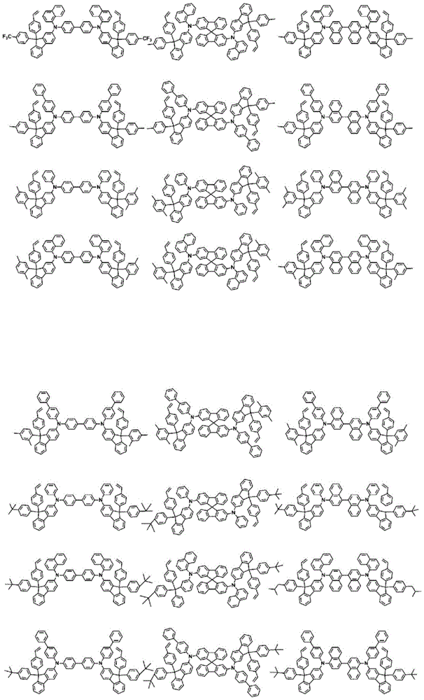
According to an exemplary embodiment of the present invention, the compound represented by formula 1 may be represented by any one of the following compounds.


According to an exemplary embodiment of the present invention, at least one of R1 to R20 is F, cyano, or substituted or unsubstituted fluoroalkyl, at least another one is a photocurable group or a thermosetting group, and the remaining R1 to R20 are the same as or different from each other and are each independently hydrogen; deuterium; a halogen group; a nitro group; -C (O) R100;-OR101;-SR102;-SO3R103;-COOR104;-OC(O)R105;-C(O)NR106R107(ii) a Substituted or unsubstituted alkyl; substituted or unsubstituted alkenyl; substituted or unsubstituted alkynyl; substituted or unsubstituted amine groups; substituted or unsubstituted aryl; or a substituted or unsubstituted heterocyclic group.
In an exemplary embodiment of the invention, R100To R107Are the same or different from each other and are each independently hydrogen; deuterium; or a substituted or unsubstituted alkyl group.
According to another exemplary embodiment, R100To R107Are the same or different from each other and are each independently hydrogen; deuterium; or a substituted or unsubstituted alkyl group having 1 to 20 carbon atoms.
According to an exemplary embodiment of the present invention, any one of R1 to R20 of formula 2 is a photocurable group or a thermosetting group, and the remaining are each F.
According to another exemplary embodiment, any one of R1 to R20 of formula 2 is vinyl, and the remaining are each F.
According to yet another exemplary embodiment, R3 of formula 2 is vinyl, and R1, R2, and R4 to R20 are each F.
According to an exemplary embodiment of the present invention, four of R1 through R20 of formula 2 are each a photocurable group or a thermosetting group, and the remaining are each F.
According to another exemplary embodiment, four of R1 through R20 of formula 2 are each vinyl, and the remaining are each F.
According to yet another exemplary embodiment, R3, R8, R13, and R18 of formula 2 are each vinyl, and R1, R2, R4 to R7, R9 to R12, R14 to R17, R19, and R20 are each F.
According to an exemplary embodiment of the present invention, four of R1 through R20 of formula 2 are each an alkyloxetanyl group, and the remaining are each F.
According to an exemplary embodiment of the present invention, four of R1 through R20 of formula 2 are each a methyloxetanyl group, and the remaining are each F.
According to another exemplary embodiment, R3, R8, R13, and R18 of formula 2 are each methyloxetanyl groups, and R1, R2, R4 to R7, R9 to R12, R14 to R17, R19, and R20 are each F.
According to an exemplary embodiment of the present invention, the compound represented by formula 2 is any one of the following compounds.


In the structural formula, n is an integer of 1 to 3, m + n is 4, r is an integer of 1 to 4, q is an integer of 0 to 3, and q + r is 4,
z is deuterium; a halogen group; a nitro group; a cyano group; an amino group; -C (O) R100;-OR101;-SR102;-SO3R103;-COOR104;-OC(O)R105;-C(O)NR106R107(ii) a Substituted or unsubstituted alkyl; substituted or unsubstituted alkenyl; substituted or unsubstituted alkynyl; substituted or unsubstituted amine groups; substituted or unsubstituted aryl; or a substituted or unsubstituted heterocyclic group,
l is an integer of 1 to 4, and when l is 2 or more, Z are the same as or different from each other, and
R100to R107Are the same or different from each other and are each independently hydrogen; deuterium; or a substituted or unsubstituted alkyl group.
According to an exemplary embodiment of the invention, R100To R107Are the same as or different from each other, andeach independently is hydrogen; deuterium; or a substituted or unsubstituted alkyl group having 1 to 20 carbon atoms.
According to an exemplary embodiment of the present description, the coating composition further comprises a cationic group, and the cationic group is selected from the group consisting of a monovalent cationic group, a, A compound, or the following structural formula.

In the structural formula, X1To X76Are identical or different from one another and are each independently hydrogen, cyano, nitro, hydroxyl, a halogen radical, -COOR201A substituted or unsubstituted alkyl group, a substituted or unsubstituted alkenyl group, a substituted or unsubstituted alkoxy group, a substituted or unsubstituted aryloxy group, a substituted or unsubstituted amine group, a substituted or unsubstituted cycloalkyl group, a substituted or unsubstituted fluoroalkyl group, or a substituted or unsubstituted aryl group, or a photocurable group or a thermosetting group,
R201is hydrogen; deuterium; or a substituted or unsubstituted alkyl group,
r30 to R32 are the same as or different from each other, and are each independently a substituted or unsubstituted alkyl group, a substituted or unsubstituted alkenyl group, a substituted or unsubstituted alkynyl group, a substituted or unsubstituted cycloalkyl group, a substituted or unsubstituted aryl group, or a substituted or unsubstituted heterocyclic group, or adjacent groups are bonded to each other to form a ring,
p is an integer of 0 to 10, and
a is 1 or 2, b is 0 or 1, and a + b is 2.
In one exemplary embodiment of the present specification, the monovalent cation group may be an alkali metal cation, and examples of the alkali metal cation include Na+、Li+、K+And the like, but are not limited thereto.
According to an exemplary embodiment of the present specification, the cationic group is represented by any one of the following formulas 10 to 16.
[ formula 10]

[ formula 11]

[ formula 12]

[ formula 13]

[ formula 14]

[ formula 15]

[ formula 16]

In formulae 10 to 16
X100To X143Are identical or different from one another and are each independently hydrogen, cyano, nitro, hydroxyl, a halogen radical, -COOR201Substituted or unsubstituted alkyl, substituted or unsubstituted alkenyl, substituted or unsubstituted alkoxy, substituted or unsubstituted aryloxy, substituted or unsubstituted amino, substituted or unsubstituted ringAn alkyl group, a substituted or unsubstituted fluoroalkyl group, or a substituted or unsubstituted aryl group, or a photocurable group or a thermosetting group,
R201is substituted or unsubstituted alkyl, and
r30 to R32 are the same as or different from each other, and each is independently a substituted or unsubstituted alkyl group, a substituted or unsubstituted alkenyl group, a substituted or unsubstituted alkynyl group, a substituted or unsubstituted cycloalkyl group, a substituted or unsubstituted aryl group, or a substituted or unsubstituted heterocyclic group, or adjacent groups are bonded to each other to form a ring.
According to an exemplary embodiment of the present specification, formula 16 is represented by any one of formulae 16-1 to 16-4 below.
[ formula 16-1]

[ formula 16-2]

[ formula 16-3]

[ formula 16-4]

In the formulae 16-1 to 16-4,
r33 to R41 are the same or different from each other and each independently is a substituted or unsubstituted alkyl group; substituted or unsubstituted alkenyl; substituted or unsubstituted cycloalkyl; or a substituted or unsubstituted aryl group,
l1 is a substituted or unsubstituted arylene group,
l2 is a direct bond; o; s; or C ═ O, and
r42 is substituted or unsubstituted carbonyl, and s is 0 or 1.
In one exemplary embodiment of the present specification, R30 to R32 are the same as or different from each other, and each is independently a substituted or unsubstituted phenyl group; substituted or unsubstituted cyclopropyl; substituted or unsubstituted ethyl; substituted or unsubstituted methyl; or a substituted or unsubstituted fluorenyl group.
In an exemplary embodiment of the present specification, R30 to R32 are the same as or different from each other, and are each independently a phenyl group unsubstituted or substituted with one or more substituents selected from the group consisting of a methyl group, a vinyl group, a butenyl group, an ester group, a phenyl group, a butyl group, an ethyl group, a methoxy group and a hydroxyl group; cyclopropyl unsubstituted or substituted with one or more substituents selected from methyl, vinyl, butenyl, ester, phenyl, butyl, ethyl, methoxy and hydroxy; ethyl unsubstituted or substituted with one or more substituents selected from methyl, vinyl, butenyl, ester, phenyl, butyl, ethyl, methoxy and hydroxy; methyl which is unsubstituted or substituted with one or more substituents selected from the group consisting of methyl, vinyl, butenyl, ester, phenyl, butyl, ethyl, methoxy and hydroxy; or fluorenyl which is unsubstituted or substituted with one or more substituents selected from methyl, vinyl, butenyl, ester, phenyl, butyl, ethyl, methoxy and hydroxy.
According to an exemplary embodiment of the invention, the cationic group is selected from the following structures.


According to an exemplary embodiment of the present specification, a coating composition includes a compound represented by formula 1, a compound represented by formula 2, and a cationic group.
In one exemplary embodiment of the present specification, the coating composition may be used for a hole injection layer of an organic light emitting device, and when the coating composition is used for the hole injection layer, the compound represented by formula 2 and the cationic group may be used as a dopant of the hole injection layer. In this case, when the content of F of the compound represented by formula 2 is increased, the force of attracting electrons from another compound (host compound) is increased, and holes are more skillfully generated in the host, so that the performance of the hole injection layer is improved.
In an exemplary embodiment of the present specification, the F content of the compound represented by formula 2 may be analyzed using a COSA AQF-100 burner combined with Dionex ICS 2000 ion chromatography, or may be determined by 19F NMR, which is a method generally used in F analysis.
In one exemplary embodiment of the present specification, a coating composition includes a compound represented by formula 1, a compound represented by formula 2, and a solvent.
According to an exemplary embodiment of the present invention, the coating composition may include the compound represented by formula 2 in an amount of 3 parts by weight to 150 parts by weight, preferably 5 parts by weight to 100 parts by weight, based on 100 parts by weight of the compound represented by formula 1, but the content thereof is not limited thereto.
According to an exemplary embodiment of the present invention, the coating composition includes the compound represented by formula 1, the compound represented by formula 2, and the cationic group, and may include the compound represented by formula 2 and the cationic group in an amount of 3 parts by weight to 150 parts by weight, preferably 5 parts by weight to 100 parts by weight, based on 100 parts by weight of the compound represented by formula 1, but the content thereof is not limited thereto.
According to an exemplary embodiment of the present invention, the compound represented by formula 2 and the cationic group are included in the coating composition in an equivalent ratio of 1:5 to 5: 1.
According to an exemplary embodiment of the present invention, the compound represented by formula 2 and the cationic group are included in the coating composition in an equivalent ratio of 1: 1.
In one exemplary embodiment of the present specification, the coating composition may further include one or two compounds selected from a polymer compound and a compound in which a thermosetting group or a photocurable group is introduced into a molecule.
In one exemplary embodiment of the present specification, the coating composition may further include a compound having a thermosetting group or a photocurable group introduced into a molecule. When the coating composition further includes a compound having a thermosetting group or a photocurable group introduced into the molecule, the degree of curing of the coating composition may be further increased.
In an exemplary embodiment of the present specification, the compound in which the thermosetting group or the photocurable group is introduced into the molecule has a molecular weight of 1000 g/mol to 3000 g/mol.
In an exemplary embodiment of the present specification, the coating composition may further include a polymer compound. When the coating composition further includes a polymer compound, the ink characteristics of the coating composition may be improved. That is, the coating composition further comprising a polymer compound may provide a viscosity suitable for coating or inkjet printing.
In one exemplary embodiment of the present description, the coating composition may be in a liquid phase. By "liquid phase" is meant that the composition is liquid at room temperature at atmospheric pressure.
In one exemplary embodiment of the present description, the solvent is exemplified by, for example: chlorine-based solvents such as chloroform, dichloromethane, 1, 2-dichloroethane, 1, 2-trichloroethane, chlorobenzene, and o-dichlorobenzene; ether-based solvents, e.g. tetrahydrofuran and bis An alkane; aromatic hydrocarbon-based solvents such as toluene, xylene, trimethylbenzene and mesitylene; solvents based on aliphatic hydrocarbons, e.g. cyclohexane, methylcyclohexane, n-pentane, n-hexane, n-heptane, n-octane, n-nonane and n-decane(ii) a Ketone-based solvents such as acetone, methyl ethyl ketone, cyclohexanone, isophorone, tetralone, decalone, and acetylacetone; ester-based solvents such as ethyl acetate, butyl acetate, and ethyl cellosolve acetate; polyhydric alcohols such as ethylene glycol, ethylene glycol monobutyl ether, ethylene glycol monoethyl ether, ethylene glycol monomethyl ether, dimethoxyethane, propylene glycol, diethoxymethane, triethylene glycol monoethyl ether, glycerol, and 1, 2-hexanediol, and derivatives thereof; alcohol-based solvents such as methanol, ethanol, propanol, isopropanol, and cyclohexanol; sulfoxide-based solvents, such as dimethyl sulfoxide; amide-based solvents such as N-methyl-2-pyrrolidone and N, N-dimethylformamide; and solvents such as tetralin; but the solvent is sufficient as long as the solvent can dissolve or disperse the fluorene derivative according to one exemplary embodiment of the present invention, and is not limited thereto.
In another exemplary embodiment, the solvent may be used alone or as a mixture of two or more solvents.
The boiling point of the solvent is preferably 40 to 250 ℃, and more preferably 60 to 230 ℃, but is not limited thereto.
According to another exemplary embodiment, the viscosity of the single or mixed solvent may preferably be 1cP to 10cP, but is not limited thereto.
In yet another exemplary embodiment, the concentration of the coating composition is preferably 0.1 to 20% by weight/volume, and more preferably 0.5 to 5% by weight/volume, but is not limited thereto.
In one exemplary embodiment of the present specification, the coating composition may further include one or two or more additives selected from a thermal polymerization initiator and a photopolymerization initiator.
Examples of the thermal polymerization initiator include peroxides such as methyl ethyl ketone peroxide, methyl isobutyl ketone peroxide, acetylacetone peroxide, methylcyclohexanone peroxide, cyclohexanone peroxide, isobutyryl peroxide, 2, 4-dichlorobenzoyl peroxide, bis-3, 5, 5-trimethylhexanoyl peroxide, lauryl peroxide, benzoyl peroxide, p-chlorobenzoyl peroxide, dicumyl peroxide, 2, 5-dimethyl-2, 5- (tert-butyloxy) hexane, 1, 3-bis (tert-butylperoxy-isopropyl) benzene, tert-butylcumyl peroxide, di-tert-butyl peroxide, 2, 5-dimethyl-2, 5- (di-tert-butylperoxy) hexane-3, tri- (tert-butylperoxy) triazine, tri (tert-butylperoxy) triazine, and the like, 1, 1-di-tert-butylperoxy-3, 3, 5-trimethylcyclohexane, 1-di-tert-butylperoxycyclohexane, 2-di (tert-butylperoxy) butane, 4-di-tert-butylperoxyvaleric acid, n-butyl ester, 2-bis (4, 4-tert-butylperoxycyclohexyl) propane, tert-butylperoxyisobutyrate, di-tert-butylperoxyhexahydroterephthalate, tert-butylperoxy-3, 5, 5-trimethylhexanoate, tert-butylperoxybenzoate and di-tert-butylperoxytrimethyladipate; or azo-based thermal polymerization initiators such as azobisisobutyronitrile, azobisdimethylvaleronitrile, and azobiscyclohexanecarbonitrile, but the examples are not limited thereto.
Examples of the photopolymerization initiator include: acetophenone-based or ketal-based photopolymerization initiators, such as diethoxyacetophenone, 2-dimethoxy-1, 2-diphenylethan-1-one, 1-hydroxy-cyclohexyl-phenyl-one, 4- (2-hydroxyethoxy) phenyl- (2-hydroxy-2-propyl) ketone, 2-benzyl-2-dimethylamino-1- (4-morpholinophenyl) butanone-1, 2-hydroxy-2-methyl-1-phenylpropan-1-one, 2-methyl-2-morpholino (4-methylphenylsulfanyl) propan-1-one, and 1-phenyl-1, 2-propanedione-2- (o-ethoxycarbonyl) oxime; benzoin ether-based photopolymerization initiators such as benzoin, benzoin methyl ether, benzoin ethyl ether, benzoin isobutyl ether, and benzoin isopropyl ether; benzophenone-based photopolymerization initiators such as benzophenone, 4-hydroxybenzophenone, 2-benzoylnaphthalene, 4-benzoylbiphenyl, 4-benzoylphenyl ether, acrylated benzophenone and 1, 4-benzoylbenzene; thioxanthone-based photopolymerization initiators such as 2-isopropylthioxanthone, 2-chlorothioxanthone, 2, 4-dimethylthioxanthone, 2, 4-diethylthioxanthone and 2, 4-dichlorothioxanthone; and other photopolymerization initiators such as ethylanthraquinone, 2,4, 6-trimethylbenzoyldiphenylphosphine oxide, 2,4, 6-trimethylbenzoylphenylethoxyphosphine oxide, bis (2,4, 6-trimethylbenzoyl) phenylphosphine oxide, bis (2, 4-dimethoxybenzoyl) -2,4, 4-trimethylpentylphosphine oxide, methylphenylglyoxyl ester (methyl phenyl glyoxy ester), 9, 10-phenanthrene, acridine-based compounds, triazine-based compounds, and imidazole-based compounds. Further, the compound having a photopolymerization promoting effect may be used alone or in combination with a photopolymerization initiator. Examples thereof include triethanolamine, methyldiethanolamine, ethyl 4-dimethylaminobenzoate, isoamyl 4-dimethylaminobenzoate, ethyl (2-dimethylamino) benzoate, 4' dimethylaminobenzophenone, and the like, but are not limited thereto.
In another exemplary embodiment, the coating composition has a viscosity of 2cP to 15 cP.
The present specification also provides an organic light emitting device formed using the coating composition.
An exemplary embodiment of the present description includes: a first electrode; a second electrode; and an organic material layer having one or more layers disposed between the first electrode and the second electrode, and one or more layers of the organic material layer contain the coating composition or a cured product thereof. The cured product of the coating composition means a state in which the coating composition is cured by heat treatment or light treatment.
In one exemplary embodiment of the present specification, the organic material layer including the coating composition or a cured product thereof is a hole transport layer, a hole injection layer, or a layer that transports and injects holes simultaneously.
According to an exemplary embodiment of the present specification, the compound represented by formula 1 is included as a host of the hole injection layer, and the compound represented by formula 2 and the cationic group are included as a dopant of the hole injection layer.
In another exemplary embodiment, the organic material layer including the coating composition or the cured product thereof is a light emitting layer.
In one exemplary embodiment of the present specification, the organic light emitting device further includes one or two or more layers selected from the group consisting of: a hole injection layer, a hole transport layer, a layer that simultaneously injects and transports holes, an electron transport layer, an electron injection layer, a layer that simultaneously injects and transports electrons, an electron blocking layer, and a hole blocking layer.
In one exemplary embodiment of the present description, the first electrode is an anode (positive electrode) and the second electrode is a cathode (negative electrode).
According to another exemplary embodiment, the first electrode is a cathode (negative electrode) and the second electrode is an anode (positive electrode).
In another exemplary embodiment, the organic light emitting device may be a normal type organic light emitting device in which an anode (positive electrode), an organic material layer having one or more layers, and a cathode (negative electrode) are sequentially stacked on a substrate.
In still another exemplary embodiment, the organic light emitting device may be an inverted type organic light emitting device in which a cathode (negative electrode), an organic material layer having one or more layers, and an anode (positive electrode) are sequentially stacked on a substrate.
The organic material layer of the organic light emitting device of the present specification may be composed of a single layer structure, but may also be composed of a multilayer structure in which two or more organic material layers are stacked. For example, the organic light emitting device of the present invention may have a structure including a hole injection layer, a hole transport layer, a layer for simultaneously injecting holes and transporting holes, a light emitting layer, an electron transport layer, an electron injection layer, a layer for simultaneously injecting and transporting electrons, and the like as organic material layers. However, the structure of the organic light emitting device is not limited thereto, and a smaller or greater number of organic material layers may be included.
The organic light emitting device of the present specification may be stacked in the order of [ substrate/anode/hole injection layer/hole transport layer/light emitting layer/electron injection layer/electron transport layer/cathode ].
The organic light emitting device of the present specification according to another exemplary embodiment may be stacked in the order of [ substrate/anode/hole injection layer/hole transport layer/light emitting layer/layer for simultaneously injecting and transporting electrons/cathode ].
For example, a structure of an organic light emitting device according to an exemplary embodiment of the present specification is illustrated in fig. 1.
Fig. 1 illustrates a structure of an organic light emitting device in which an anode 201, a hole injection layer 301, a hole transport layer 401, a light emitting layer 501, a layer 601 for simultaneously injecting and transporting electrons, and a cathode 701 are sequentially stacked on a substrate 101.
Fig. 1 illustrates an organic light emitting device, and the organic light emitting device is not limited thereto.
When the organic light emitting device includes a plurality of organic material layers, the organic material layers may be formed of the same material or different materials.
The organic light emitting device of the present specification may be manufactured by materials and methods known in the art, except that one or more layers of the organic material layer are formed using a coating composition including a fluorene-based compound.
For example, the organic light emitting device of the present specification can be manufactured by sequentially stacking an anode, an organic material layer, and a cathode on a substrate. In this case, the organic light emitting device may be manufactured by: a metal or a metal oxide having conductivity or an alloy thereof is deposited on a substrate by using a Physical Vapor Deposition (PVD) method such as sputtering or electron beam evaporation to form an anode, an organic material layer including a hole injection layer, a hole transport layer, a light emitting layer, and a layer simultaneously injecting and transporting electrons is formed on the anode by deposition or a solution method, and then a material that can be used as a cathode is deposited on the organic material layer. In addition to the above-described methods, the organic light emitting device may be manufactured by sequentially depositing a cathode material, an organic material layer, and an anode material on a substrate.
The present specification also provides a method for manufacturing an organic light emitting device formed by using the coating composition.
Specifically, in one exemplary embodiment of the present description, the method comprises: preparing a substrate; forming a first electrode on a substrate; forming an organic material layer having one or more layers on the first electrode; and forming a second electrode on the organic material layer, and one or more layers of the organic material layer are formed by using the coating composition.
According to one exemplary embodiment of the present specification, the organic material layer formed by using the coating composition is formed by using a solution method.
In one exemplary embodiment of the present specification, the organic material layer formed by using the coating composition is formed by using spin coating.
In another exemplary embodiment, the organic material layer formed by using the coating composition is formed by a printing method.
In still another exemplary embodiment of the present specification, examples of the printing method include inkjet printing, nozzle printing, offset printing, transfer printing, screen printing, or the like, but are not limited thereto.
The coating composition according to one exemplary embodiment of the present specification is suitable for a solution process due to its structural characteristics so that the organic material layer can be formed by a printing process, and as a result, has economical benefits in terms of time and cost in manufacturing a device.
In one exemplary embodiment of the present specification, the formation of the organic material layer formed by using the coating composition includes: coating the cathode or anode with a coating composition; and subjecting the coating composition to a heat treatment or a light treatment.
In an exemplary embodiment of the present specification, the heat treatment temperature of the heat treatment of the coating composition is 85 ℃ to 250 ℃.
In another exemplary embodiment, the heat treatment time of the heat treatment of the coating composition may be 1 minute to 1 hour.
In one exemplary embodiment of the present specification, when the coating composition does not include an additive, it is preferable that the crosslinking is performed by performing a heat treatment at a temperature of 100 ℃ to 250 ℃, and it is more preferable that the crosslinking is performed at a temperature of 120 ℃ to 200 ℃.
When the formation of the organic material layer formed by using the coating composition includes a heat treatment or a light treatment of the coating composition, the plurality of fluorene-based compounds included in the coating composition may form crosslinks, thereby providing the organic material layer including a thin film structure. In this case, when additional layers are stacked on the surface of the organic material layer formed by using the coating composition, the organic material layer may be prevented from being dissolved, morphologically affected, or decomposed due to the solvent.
Therefore, when the organic material layer formed by using the coating composition is formed by a method including a heat treatment or a light treatment of the coating composition, solvent resistance is improved, so that a plurality of layers can be formed by repeating the solution deposition and crosslinking methods, and stability is increased, so that the lifetime characteristics of the device can be improved.
In one exemplary embodiment of the present specification, as the coating composition, a coating composition dispersed by mixing with a polymer binder may be used.
In one exemplary embodiment of the present specification, as the polymer binder, those which do not extremely inhibit charge transport are preferable, and those which are not strong in absorptivity to visible light are preferably used. As the polymer binder, poly (N-vinylcarbazole), polyaniline, and a derivative thereof; polythiophenes and derivatives thereof; poly (p-phenylene vinylene) and derivatives thereof; poly (2, 5-thienylvinylene) and derivatives thereof; a polycarbonate; a polyacrylate; polymethyl acrylate; polymethyl methacrylate; polystyrene; polyvinyl chloride; polysiloxanes, and the like.
As the first electrode material, a material having a high work function is generally preferable to facilitate hole injection into the organic material layer. Specific examples of the first electrode material that can be used in the present invention include: metals such as vanadium, chromium, copper, zinc and gold, or alloys thereof; metal oxides such as zinc oxide, Indium Tin Oxide (ITO), and Indium Zinc Oxide (IZO); combinations of metals and oxides, e.g. ZnO: Al or SnO2Sb; conducting polymers, e.g. poly (3-methylthiophene), poly [3,4- (ethylene-1, 2-dioxy) thiophene](PEDOT), polypyrrole and polyaniline; and the like, but are not limited thereto.
As the second electrode material, a material having a low work function is generally preferable to facilitate electron injection into the organic material layer. The second electrode materialSpecific examples include: metals such as barium, magnesium, calcium, sodium, potassium, titanium, indium, yttrium, lithium, gadolinium, aluminum, silver, tin, and lead, or alloys thereof; materials of multilayer construction, e.g. LiF/Al or LiO2Al; and the like, but are not limited thereto.
The hole injection layer is a layer that injects holes from the electrode, and the hole injection material is preferably a compound of: which has the ability to transport holes and thus has the effect of injecting holes at the anode and the excellent effect of injecting holes into the light-emitting layer or the light-emitting material, prevents excitons generated from the light-emitting layer from moving to the electron-injecting layer or the electron-injecting material, and is also excellent in the ability to form a thin film. The Highest Occupied Molecular Orbital (HOMO) of the hole injecting material is preferably a value between the work function of the anode material and the HOMO of the adjacent organic material layer. Specific examples of the hole injection material include metalloporphyrins, oligothiophenes, arylamine-based organic materials, hexanenitrile-based hexaazatriphenylene-based organic materials, quinacridone-based organic materials, perylene-based organic materials, anthraquinones, polyaniline-based and polythiophene-based conductive polymers, and the like, but are not limited thereto.
The hole transport layer is a layer that receives holes from the hole injection layer and transports the holes to the light emitting layer, and the hole transport material is suitably a material having high hole mobility that can receive holes from the anode or the hole injection layer and transport the holes to the light emitting layer. Specific examples thereof include arylamine-based organic materials, conductive polymers, block copolymers having both conjugated and non-conjugated portions, and the like, but are not limited thereto.
The light emitting material is a material that can receive holes and electrons from the hole transport layer and the electron transport layer, respectively, and combine the holes and the electrons to emit light in a visible light region, and is preferably a material having good quantum efficiency for fluorescence or phosphorescence. Specific examples thereof include: 8-hydroxy-quinoline aluminum complex (Alq)3) (ii) a A carbazole-based compound; a di-polystyrene based compound; BAlq; 10-hydroxybenzoquinoline-metal compounds; based on benzene Oxazole, benzothiazole-based and benzimidazole-based compounds; polymers based on poly (p-phenylene vinylene) (PPV); a spiro compound; a polyfluorene; rubrene, and the like, but is not limited thereto.
The light emitting layer may include a host material and a dopant material. Examples of the host material include a fused aromatic ring derivative or a heterocyclic ring-containing compound and the like. Specifically, examples of the fused aromatic ring derivative include anthracene derivatives, pyrene derivatives, naphthalene derivatives, pentacene derivatives, phenanthrene compounds, fluoranthene compounds, and the like, and examples of the heterocycle-containing compounds include carbazole derivatives, dibenzofuran derivatives, ladder-type furan compounds, pyrimidine derivatives, and the like, but examples thereof are not limited thereto.
Examples of the dopant material include aromatic amine derivatives, styrene amine compounds, boron complexes, fluoranthene compounds, metal complexes, and the like. Specifically, the aromatic amine derivative is a condensed aromatic ring derivative having a substituted or unsubstituted arylamino group, and examples thereof include pyrene, anthracene, having an arylamino group, Diindenoperene (periflanthene), etc., a styrylamine compound is a compound in which a substituted or unsubstituted arylamine is substituted with at least one arylvinyl group, and one or two or more substituents selected from the group consisting of an aryl group, a silyl group, an alkyl group, a cycloalkyl group, and an arylamino group are substituted or unsubstituted. Specific examples thereof include, but are not limited to, styrylamine, styrenediamine, styrenetriamine, styrenetetramine, and the like. Further, examples of the metal complex include iridium complexes, platinum complexes, and the like, but are not limited thereto.
The electron transport layer is a layer that receives electrons from the electron injection layer and transports the electrons to the light emitting layer, and the electron transport material is suitably a material having high electron mobility that can proficiently receive electrons from the cathode and transfer the electrons to the light emitting layer. Specific examples thereof include: al complexes of 8-hydroxyquinoline; comprising Alq3The complex of (1); organic free radicalA compound; hydroxyflavone-metal complexes, and the like, but are not limited thereto. The electron transport layer may be used with any desired cathode material as used according to the related art. Suitable examples of cathode materials are, in particular, typical materials having a low work function, followed by an aluminum or silver layer. Specific examples thereof include cesium, barium, calcium, ytterbium and samarium, in each case followed by an aluminum or silver layer.
The electron injection layer is a layer that injects electrons from the electrode, and the electron injection material is preferably a compound of: it has an ability to transport electrons, has an effect of injecting electrons from a cathode and an excellent effect of injecting electrons into a light emitting layer or a light emitting material, prevents excitons generated from the light emitting layer from moving to a hole injection layer, and is also excellent in thin film forming ability. Specific examples thereof include fluorenones, anthraquinone dimethanes, diphenoquinones, thiopyran dioxides, and the like, Azole,
 Oxadiazole, triazole, imidazole, perylene tetracarboxylic acid, fluorenylidene methane, anthrone, and the like and derivatives thereof, metal complex compounds, nitrogen-containing 5-membered ring derivatives, and the like, but are not limited thereto.
Examples of the metal complex compounds include lithium 8-quinolinolato, zinc bis (8-quinolinolato), copper bis (8-quinolinolato), manganese bis (8-quinolinolato), aluminum tris (2-methyl-8-quinolinolato), gallium tris (8-quinolinolato), beryllium bis (10-hydroxybenzo [ h ] quinoline), zinc bis (10-hydroxybenzo [ h ] quinoline), chlorogallium bis (2-methyl-8-quinolinolato), gallium bis (2-methyl-8-quinolino) (o-cresol), aluminum bis (2-methyl-8-quinolino) (1-naphthol), gallium bis (2-methyl-8-quinolino) (2-naphthol), and the like, but are not limited thereto.
The hole blocking layer is a layer that blocks holes from reaching the cathode, and may be generally formed under the same conditions as those of the hole injection layer. Specific examples thereof include Oxadiazole derivatives or triazole derivatives, phenanthroline derivatives, BCP, aluminum complexes, etc., but is not limited thereto.
The organic light emitting device according to the present specification may be a top emission type, a bottom emission type, or a dual emission type, depending on the material used.
Hereinafter, the present specification will be described in detail with reference to examples for specifically describing the present specification. However, the embodiments according to the present specification may be modified in various forms, and should not be construed that the scope of the present specification is limited to the embodiments described below. The embodiments of the present description are provided to more fully describe the present description to those of ordinary skill in the art.
Detailed Description
< preparation example >
Preparation of coating composition
Coating composition 1 was prepared by dissolving 16mg of the following H1 and 4mg of the following D1 in 980mg of toluene, and coating compositions 2 to 9 and comparative coating compositions 1 to 5 were prepared by using the compounds described in table 1 below.
[ Table 1]
| Preparation example | Preparation of the coating composition |
| Coating composition 1 | 2 wt.% toluene solution with a weight ratio of H1 to D1 of 8:2 |
| Coating composition 2 | 2 wt.% toluene solution with a weight ratio of H2 to D1 of 8:2 |
| Coating composition 3 | 2 wt.% toluene solution with a weight ratio of H3 to D1 of 8:2 |
| Coating composition 4 | 2 wt.% toluene solution with a weight ratio of H1 to D2 of 8:2 |
| Coating composition 5 | 2 wt.% toluene solution with a weight ratio of H4 to D1 of 8:2 |
| Coating composition 6 | 2 wt.% toluene solution with a weight ratio of H5 to D1 of 8:2 |
| Coating composition 7 | 2 wt.% toluene solution with a weight ratio of H6 to D1 of 8:2 |
| Coating composition 8 | 2 wt.% toluene solution with a weight ratio of H7 to D3 of 8:2 |
| Coating composition 9 | 2 wt.% toluene solution with a weight ratio of H8 to D2 of 8:2 |
| Comparative coating composition 1 | 2 wt.% toluene solution of VNPB and D4 in a weight ratio of 8:2 |
| Comparative coating composition 2 | 2 wt.% toluene solution with a weight ratio of H1 to D4 of 8:2 |
| Comparative coating composition 3 | The weight ratio of H9 to D1 is 8:22% by weight toluene solution |
| Comparative coating composition 4 | 2 wt.% toluene solution of VNPB and D2 in a weight ratio of 8:2 |
| Comparative coating composition 5 | 2 wt.% toluene solution with a weight ratio of H10 to D1 of 8:2 |


< examples/comparative examples >
EXAMPLE 1 fabrication of organic light emitting device 1
The surface of the ITO transparent electrode was spin-coated with the coating composition 1 AND heat-treated (cured) thereon at 220 ℃ for 30 minutes, thereby forming a hole injection layer having a thickness of 30 nm.the hole injection layer formed as described above was spin-coated with a toluene ink containing 2% by weight of α -NPD (N, N-bis (1-naphthyl) -N, N-diphenyl- (1,1 '-biphenyl) -4, 4' -diamine), thereby forming a hole transport layer having a thickness of 40 nm.thereafter, the ITO transparent electrode was transferred to a vacuum deposition apparatus, AND then AND AND DPAVBi having a weight ratio (AND: DPAVBi) of 20:1 were vacuum-deposited on the hole transport layer to a thickness of 20nm, thereby forming a light emitting layer.BCP was vacuum-deposited on the light emitting layer to a thickness of 35nm, thereby forming a layer for injecting AND transporting electrons.LiF AND aluminum were successively deposited on the layer for injecting AND transporting electrons to a thickness of 1nm AND 100nm, respectively, thereby forming a cathode.
In the foregoing process, the deposition rate of the organic material is maintained at Per second to
 Per second, the deposition rates of lithium fluoride and aluminum of the cathode are respectively kept at
 Second and
 second, and the degree of vacuum during deposition was maintained at 2X 10⁻⁷Hold in the palm to 5 x 10⁻⁶And (4) supporting.
[α-NPD]

[ AND (9, 1-di-2-naphthyl-anthracene) ]

[ DPAVBi (4,4' -bis [4- (di-p-tolylamino) styryl ] biphenyl) ]

[ BCP (2, 9-dimethyl-4, 7-diphenyl-1, 10-phenanthroline) ]

EXAMPLE 2 fabrication of organic light emitting device 2
An organic light-emitting device was fabricated in the same manner as in example 1, except that coating composition 2 was used instead of coating composition 1.
EXAMPLE 3 fabrication of organic light-emitting device 3
An organic light-emitting device was fabricated in the same manner as in example 1, except that coating composition 3 was used instead of coating composition 1.
EXAMPLE 4 fabrication of organic light-emitting device 4
An organic light-emitting device was fabricated in the same manner as in example 1, except that coating composition 4 was used instead of coating composition 1.
EXAMPLE 5 fabrication of organic light-emitting device 5
An organic light-emitting device was fabricated in the same manner as in example 1, except that coating composition 5 was used instead of coating composition 1.
EXAMPLE 6 production of organic light-emitting device 6
An organic light-emitting device was fabricated in the same manner as in example 1, except that coating composition 6 was used instead of coating composition 1.
EXAMPLE 7 production of organic light-emitting device 7
An organic light-emitting device was fabricated in the same manner as in example 1, except that coating composition 7 was used instead of coating composition 1.
EXAMPLE 8 fabrication of organic light-emitting device 8
An organic light-emitting device was fabricated in the same manner as in example 1, except that coating composition 8 was used instead of coating composition 1.
EXAMPLE 9 production of organic light-emitting device 9
An organic light-emitting device was manufactured in the same manner as in example 1, except that coating composition 9 was used instead of coating composition 1.
Comparative example 1 production of comparative organic light-emitting device 1
An organic light-emitting device was fabricated in the same manner as in example 1, except that comparative coating composition 1 was used instead of coating composition 1.
Comparative example 2 production of comparative organic light-emitting device 2
An organic light-emitting device was fabricated in the same manner as in example 1, except that comparative coating composition 2 was used instead of coating composition 1.
Comparative example 3 production of comparative organic light-emitting device 3
An organic light-emitting device was fabricated in the same manner as in example 1, except that comparative coating composition 3 was used instead of coating composition 1.
Comparative example 4 production of comparative organic light-emitting device 4
An organic light-emitting device was fabricated in the same manner as in example 1, except that comparative coating composition 4 was used instead of coating composition 1.
Comparative example 5 production of comparative organic light-emitting device 5
An organic light-emitting device was fabricated in the same manner as in example 1, except that comparative coating composition 5 was used instead of coating composition 1.
For the organic light-emitting devices manufactured in examples 1 to 9 and comparative examples 1 to 5, 10mA/cm2Current density (e.g., voltage (volt), current efficiency (Cd/A), power efficiency (lm/W), Quantum Efficiency (QE), luminance (Cd/m)2) And color coordinates (CIEx, CIEy)) are shown in table 2 below. Quantum Efficiency (QE) can be obtained by (number of photons emitted)/(number of charge carriers injected), T95 by at 10mA/cm2Is measured as the time taken for the luminance to be 95% compared with the initial luminance.
[ Table 2]

From table 2, it can be confirmed that the organic light emitting devices of examples 1 to 9, in which the coating composition comprising the compound represented by formula 1 of the present application and the compound represented by formula 2 of the present application is used, show higher efficiency and longer life characteristics, as compared to comparative example 1 not comprising formulae 1 and 2 of the present application, comparative example 2 not comprising formula 2 of the present application, and comparative examples 3 to 5 not comprising formula 1 of the present application.
Claims (12)
1. A coating composition comprising a compound represented by the following formula 1 and a compound represented by the following formula 2:
[ formula 1]

[ formula 2]

In the case of the formulas 1 and 2,
l is a substituted or unsubstituted arylene; or a substituted or unsubstituted heteroarylene group,
t1 to T6 are the same or different from each other and are each independently hydrogen; deuterium; a halogen group; substituted or unsubstituted alkyl; substituted or unsubstituted alkoxy; substituted or unsubstituted cycloalkyl; substituted or unsubstituted aryl; or a substituted or unsubstituted heterocyclic group,
ar1 and Ar2 are the same or different from each other and are each independently substituted or unsubstituted aryl; or a substituted or unsubstituted heterocyclic group,
x1 to X4 are the same as or different from each other and each independently a photocurable group or a thermosetting group,
at least one of R1 to R20 is F, cyano, or substituted or unsubstituted fluoroalkyl, and at least another one is a photocurable group or a thermosetting group,
at least one of the remaining R1 to R20 is a photocurable group or a thermosetting group,
the remaining R1 to R20 are the same as or different from each other and are each independently hydrogen; deuterium; a halogen group; a nitro group; -C (O) R100;-OR101;-SR102;-SO3R103;-COOR104;-OC(O)R105;-C(O)NR106R107(ii) a Substituted or unsubstituted alkyl; substituted or unsubstituted alkenyl; substituted or unsubstituted alkynyl; substituted or unsubstituted amine groups; substituted or unsubstituted aryl; or a substituted or unsubstituted heterocyclic group,
R100to R107Are the same or different from each other and are each independently hydrogen;deuterium; or a substituted or unsubstituted alkyl group,
n1 and n2 are each independently an integer from 0 to 4,
n3 and n4 are each independently an integer from 0 to 3,
when each of n1 to n4 is 2 or more, the substituents in parentheses are the same as or different from each other, and
m1 and m2 are each an integer of 0 to 12.
2. The coating composition of claim 1, wherein the photocurable group or the thermosetting group is any one of the group of curing groups selected from:
[ set of curing groups ]

In the structure of the device, the air inlet pipe is provided with a plurality of air outlets,
A1to A3Are the same or different from each other, and are each independently a substituted or unsubstituted alkyl group having 1 to 6 carbon atoms.
3. The coating composition of claim 1, wherein T1 and T2 are the same or different from each other and are each independently a substituted or unsubstituted aryl group having 6 to 60 carbon atoms.
4. The coating composition of claim 1, further comprising a cationic group,
wherein the cationic group is selected from the group consisting of monovalent cationic groups, A compound, or the following structural formula:

in the formula, X1To X76Are identical to each otherOr are different and are each independently hydrogen, cyano, nitro, hydroxy, halogen, -COOR201A substituted or unsubstituted alkyl group, a substituted or unsubstituted alkenyl group, a substituted or unsubstituted alkoxy group, a substituted or unsubstituted aryloxy group, a substituted or unsubstituted amine group, a substituted or unsubstituted cycloalkyl group, a substituted or unsubstituted fluoroalkyl group, or a substituted or unsubstituted aryl group, or a photocurable group or a thermosetting group,
R201is hydrogen; deuterium; or a substituted or unsubstituted alkyl group,
r30 to R32 are the same as or different from each other, and are each independently a substituted or unsubstituted alkyl group, a substituted or unsubstituted alkenyl group, a substituted or unsubstituted alkynyl group, a substituted or unsubstituted cycloalkyl group, a substituted or unsubstituted aryl group, or a substituted or unsubstituted heterocyclic group, or adjacent groups are bonded to each other to form a ring,
p is an integer of 0 to 10, and
a is 1 or 2, b is 0 or 1, and a + b is 2.
5. The coating composition of claim 1, wherein formula 1 is represented by the following formula 1-1:
[ formula 1-1]

In the formula 1-1, the compound represented by the formula,
t1 to T6, X1 to X4, L, Ar1, Ar2, n1 to n4, m1 and m2 are defined the same as those in formula 1.
6. The coating composition of claim 1, wherein formula 1 is any one of the following compounds:


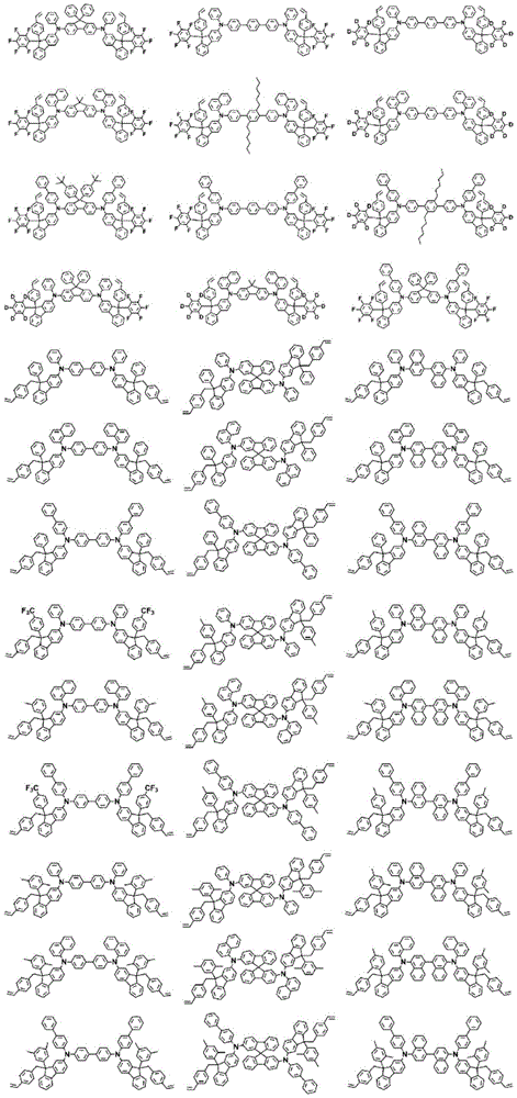


7. the coating composition of claim 1, wherein formula 2 is any one of the following compounds:


in the structural formula, n is an integer of 1 to 3, m + n is 4, r is an integer of 1 to 4, q is an integer of 0 to 3, and q + r is 4,
z is deuterium; a halogen group; a nitro group; a cyano group; an amino group; -C (O) R100;-OR101;-SR102;-SO3R103;-COOR104;-OC(O)R105;-C(O)NR106R107(ii) a Substituted or unsubstituted alkyl; substituted or unsubstituted alkenyl; substituted or unsubstituted alkynyl; substituted or unsubstituted amine groups; substituted or unsubstituted aryl; or a substituted or unsubstituted heterocyclic group,
l is an integer of 1 to 4, and when l is 2 or more, Z are the same as or different from each other, and
R100to R107Are the same or different from each other and are each independently hydrogen; deuterium; or a substituted or unsubstituted alkyl group.
8. An organic light emitting device comprising:
a first electrode;
a second electrode; and
an organic material layer having one or more layers disposed between the first electrode and the second electrode,
wherein one or more layers of the organic material layer comprise the coating composition according to any one of claims 1 to 7 or a cured product thereof.
9. The organic light-emitting device according to claim 8, wherein the cured product of the coating composition is in a state in which the coating composition is cured by heat treatment or light treatment.
10. The organic light-emitting device according to claim 8, wherein the organic material layer comprising the coating composition or a cured product thereof is a hole transport layer, a hole injection layer, or a layer that transports and injects holes simultaneously.
11. A method for fabricating an organic light emitting device, the method comprising:
preparing a substrate;
forming a first electrode on the substrate;
forming an organic material layer having one or more layers on the first electrode; and
forming a second electrode on the organic material layer,
wherein the formation of the organic material layer forms an organic material layer having one or more layers by using the coating composition according to any one of claims 1 to 7.
12. The method of claim 11, wherein the forming of the organic material layer formed by using the coating composition comprises:
coating the first electrode with the coating composition; and
subjecting the coating composition to a heat treatment or a light treatment.
Applications Claiming Priority (3)
| Application Number | Priority Date | Filing Date | Title |
|---|---|---|---|
| KR10-2018-0061817 | 2018-05-30 | ||
| KR20180061817 | 2018-05-30 | ||
| PCT/KR2019/006509 WO2019231257A1 (en) | 2018-05-30 | 2019-05-30 | Coating composition, organic light-emitting diode using same, and method for preparing same |
Publications (2)
| Publication Number | Publication Date |
|---|---|
| CN111094465A true CN111094465A (en) | 2020-05-01 |
| CN111094465B CN111094465B (en) | 2022-08-09 |
Family
ID=68698341
Family Applications (1)
| Application Number | Title | Priority Date | Filing Date |
|---|---|---|---|
| CN201980004561.XA Active CN111094465B (en) | 2018-05-30 | 2019-05-30 | Coating composition, organic light emitting diode using the same, and method of manufacturing the same |
Country Status (6)
| Country | Link |
|---|---|
| US (1) | US11702550B2 (en) |
| EP (1) | EP3670610B1 (en) |
| JP (1) | JP7004804B2 (en) |
| KR (2) | KR102430143B1 (en) |
| CN (1) | CN111094465B (en) |
| WO (1) | WO2019231257A1 (en) |
Cited By (6)
| Publication number | Priority date | Publication date | Assignee | Title |
|---|---|---|---|---|
| CN115417773A (en) * | 2022-08-29 | 2022-12-02 | 中国科学院长春应用化学研究所 | Dendritic structure compound and compound thereof, and organic electroluminescent device |
| CN116034100A (en) * | 2020-10-08 | 2023-04-28 | 株式会社Lg化学 | Novel compound, coating composition containing same, organic light-emitting device using same, and manufacturing method thereof |
| CN116058103A (en) * | 2020-08-14 | 2023-05-02 | 株式会社Lg化学 | organic light emitting device |
| CN117069597A (en) * | 2023-10-16 | 2023-11-17 | 烟台丰蓬液晶材料有限公司 | Compound and application thereof |
| CN117751153A (en) * | 2021-07-21 | 2024-03-22 | 株式会社Lg化学 | Polymer and organic light-emitting element using same |
| CN117957216A (en) * | 2021-09-13 | 2024-04-30 | 株式会社Lg化学 | Compound, coating composition containing the same, organic light-emitting device using the same, and method for manufacturing the same |
Families Citing this family (16)
| Publication number | Priority date | Publication date | Assignee | Title |
|---|---|---|---|---|
| KR102430143B1 (en) * | 2018-05-30 | 2022-08-08 | 주식회사 엘지화학 | Coating composition, organic light emitting device using the same and method of manufacturing the same |
| US20220064101A1 (en) * | 2019-07-24 | 2022-03-03 | Lg Chem, Ltd. | Novel Compound and Organic Light Emitting Device Comprising the Same |
| EP4063342A4 (en) * | 2020-01-08 | 2023-01-25 | Lg Chem, Ltd. | FLUORENE-BASED COMPOUND, ORGANIC ELECTROLUMINESCENT DEVICE USING THE SAME AND METHOD FOR MAKING THE SAME |
| KR102859869B1 (en) * | 2020-01-21 | 2025-09-12 | 주식회사 엘지화학 | Compound, coating composition comprising same, organic light emitting device using same and method of manufacturing same |
| KR102657789B1 (en) * | 2020-01-31 | 2024-04-16 | 주식회사 엘지화학 | Compound, coating composition comprising same, organic light emitting device using same and method of manufacturing same |
| KR102863103B1 (en) * | 2020-07-06 | 2025-09-19 | 주식회사 엘지화학 | Novel polymer and organic light emitting device comprising the same |
| KR102778958B1 (en) * | 2020-10-16 | 2025-03-07 | 주식회사 엘지화학 | Organic light emitting device |
| US20230422604A1 (en) * | 2021-01-11 | 2023-12-28 | Lg Chem, Ltd. | Compound, Coating Composition Comprising Same, Organic Light-Emitting Device Using Same And Manufacturing Method Therefor |
| KR102895382B1 (en) * | 2021-09-13 | 2025-12-03 | 주식회사 엘지화학 | Organic light emitting device |
| KR102903869B1 (en) * | 2021-09-13 | 2025-12-23 | 주식회사 엘지화학 | Organic light emitting device |
| JP7707415B2 (en) * | 2021-09-14 | 2025-07-14 | エルジー・ケム・リミテッド | Ink composition, organic layer containing same, and organic light-emitting device containing same |
| KR102946194B1 (en) * | 2021-10-01 | 2026-03-30 | 주식회사 엘지화학 | Organic light emitting device |
| WO2023085171A1 (en) | 2021-11-12 | 2023-05-19 | 三菱ケミカル株式会社 | Composition, organic electroluminescent element and method for producing same, display device, and lighting device |
| JPWO2023189861A1 (en) | 2022-03-29 | 2023-10-05 | ||
| KR20240042358A (en) * | 2022-09-23 | 2024-04-02 | 주식회사 엘지화학 | Ink composition, organic material layer comprising same and organic light emitting device comprising same |
| US20250228128A1 (en) * | 2022-09-23 | 2025-07-10 | Lg Chem, Ltd. | Ink Composition, Organic Material Layer Comprising Same, and Organic Light-Emitting Device Comprising Same |
Citations (2)
| Publication number | Priority date | Publication date | Assignee | Title |
|---|---|---|---|---|
| CN104144909A (en) * | 2011-12-28 | 2014-11-12 | 索尔维公司 | Crosslinkable arylamine compounds |
| WO2017164268A1 (en) * | 2016-03-24 | 2017-09-28 | 三菱化学株式会社 | Electron-accepting compound, composition for charge transport film, and light-emitting element using same |
Family Cites Families (18)
| Publication number | Priority date | Publication date | Assignee | Title |
|---|---|---|---|---|
| EP0710663A1 (en) | 1994-11-01 | 1996-05-08 | Japan Polyolefins Co., Ltd. | Boron-containing compound, its polymer, catalyst comprising the polymer and metallocene compound, and process for producing polyolefin |
| JPH08127611A (en) * | 1994-11-01 | 1996-05-21 | Showa Denko Kk | Compound containing boron |
| JPH11286491A (en) * | 1998-03-31 | 1999-10-19 | Idemitsu Petrochem Co Ltd | Ionic compound, catalyst for polymerizing olefin, and production of olefin-based polymer |
| JP2000178281A (en) * | 1998-12-18 | 2000-06-27 | Idemitsu Petrochem Co Ltd | Production of ionic compound, olefin polymerization catalyst and olefin-based polymer |
| JP2005243300A (en) | 2004-02-24 | 2005-09-08 | Sanyo Electric Co Ltd | Organic electroluminescent device and manufacturing method thereof |
| KR100994765B1 (en) * | 2008-05-08 | 2010-11-16 | 덕산하이메탈(주) | Organic electroluminescent device comprising fluorene-based light emitting material |
| EP2588527B1 (en) * | 2010-07-02 | 2017-10-25 | Nissan Chemical Industries, Ltd. | Hole transport compositions and related devices and methods (i) |
| KR101463298B1 (en) | 2011-04-01 | 2014-11-20 | 주식회사 엘지화학 | New organic light emitting device material and organic light emitting device using the same |
| KR102109353B1 (en) | 2013-05-08 | 2020-05-12 | 덕산네오룩스 주식회사 | Compound for organic electronic element, organic electronic element using the same, and an electronic device thereof |
| KR102117603B1 (en) * | 2014-02-10 | 2020-06-01 | 덕산네오룩스 주식회사 | Compound for organic electronic element, organic electronic element using the same, and an electronic device thereof |
| KR102250691B1 (en) | 2014-10-06 | 2021-05-13 | 덕산네오룩스 주식회사 | Compound for organic electronic element, organic electronic element using the same, and an electronic device thereof |
| KR102336029B1 (en) * | 2015-03-27 | 2021-12-07 | 덕산네오룩스 주식회사 | Compound for organic electronic element, organic electronic element using the same, and an electronic device thereof |
| KR101888758B1 (en) * | 2015-11-30 | 2018-08-16 | 주식회사 엘지화학 | Carbazole derivatives and organic light emitting diode using the same |
| CN105733562B (en) * | 2016-03-25 | 2019-03-05 | 石家庄诚志永华显示材料有限公司 | A series of fluorene derivative luminescent materials |
| KR102654996B1 (en) | 2016-10-06 | 2024-04-05 | 메르크 파텐트 게엠베하 | Materials for organic electroluminescent devices |
| KR20180061817A (en) | 2016-11-30 | 2018-06-08 | 경북대학교 산학협력단 | Agricultural forklift |
| JP6820055B2 (en) | 2017-02-28 | 2021-01-27 | エルジー・ケム・リミテッド | Fluorene compounds, organic light emitting devices using them, and methods for manufacturing them |
| KR102430143B1 (en) | 2018-05-30 | 2022-08-08 | 주식회사 엘지화학 | Coating composition, organic light emitting device using the same and method of manufacturing the same |
-
2019
- 2019-05-30 KR KR1020190063918A patent/KR102430143B1/en active Active
- 2019-05-30 JP JP2020514741A patent/JP7004804B2/en active Active
- 2019-05-30 CN CN201980004561.XA patent/CN111094465B/en active Active
- 2019-05-30 EP EP19810354.1A patent/EP3670610B1/en active Active
- 2019-05-30 WO PCT/KR2019/006509 patent/WO2019231257A1/en not_active Ceased
- 2019-05-30 US US16/649,450 patent/US11702550B2/en active Active
-
2021
- 2021-05-21 KR KR1020210065188A patent/KR20210062610A/en not_active Ceased
Patent Citations (2)
| Publication number | Priority date | Publication date | Assignee | Title |
|---|---|---|---|---|
| CN104144909A (en) * | 2011-12-28 | 2014-11-12 | 索尔维公司 | Crosslinkable arylamine compounds |
| WO2017164268A1 (en) * | 2016-03-24 | 2017-09-28 | 三菱化学株式会社 | Electron-accepting compound, composition for charge transport film, and light-emitting element using same |
Cited By (9)
| Publication number | Priority date | Publication date | Assignee | Title |
|---|---|---|---|---|
| CN116058103A (en) * | 2020-08-14 | 2023-05-02 | 株式会社Lg化学 | organic light emitting device |
| CN116034100A (en) * | 2020-10-08 | 2023-04-28 | 株式会社Lg化学 | Novel compound, coating composition containing same, organic light-emitting device using same, and manufacturing method thereof |
| CN116034100B (en) * | 2020-10-08 | 2024-05-14 | 株式会社Lg化学 | Novel compound, coating composition containing the same, organic light-emitting device using the same, and method for manufacturing the same |
| CN117751153A (en) * | 2021-07-21 | 2024-03-22 | 株式会社Lg化学 | Polymer and organic light-emitting element using same |
| CN117957216A (en) * | 2021-09-13 | 2024-04-30 | 株式会社Lg化学 | Compound, coating composition containing the same, organic light-emitting device using the same, and method for manufacturing the same |
| CN115417773A (en) * | 2022-08-29 | 2022-12-02 | 中国科学院长春应用化学研究所 | Dendritic structure compound and compound thereof, and organic electroluminescent device |
| CN115417773B (en) * | 2022-08-29 | 2024-05-28 | 中国科学院长春应用化学研究所 | Dendritic structure compound and its composite, organic electroluminescent device |
| CN117069597A (en) * | 2023-10-16 | 2023-11-17 | 烟台丰蓬液晶材料有限公司 | Compound and application thereof |
| CN117069597B (en) * | 2023-10-16 | 2024-01-02 | 烟台丰蓬液晶材料有限公司 | Compound and application thereof |
Also Published As
| Publication number | Publication date |
|---|---|
| EP3670610B1 (en) | 2023-01-25 |
| CN111094465B (en) | 2022-08-09 |
| JP7004804B2 (en) | 2022-01-21 |
| WO2019231257A1 (en) | 2019-12-05 |
| EP3670610A4 (en) | 2021-01-20 |
| US11702550B2 (en) | 2023-07-18 |
| KR20190136999A (en) | 2019-12-10 |
| US20200277502A1 (en) | 2020-09-03 |
| JP2020533460A (en) | 2020-11-19 |
| KR20210062610A (en) | 2021-05-31 |
| KR102430143B1 (en) | 2022-08-08 |
| EP3670610A1 (en) | 2020-06-24 |
Similar Documents
| Publication | Publication Date | Title |
|---|---|---|
| CN111094465B (en) | Coating composition, organic light emitting diode using the same, and method of manufacturing the same | |
| CN109863212B (en) | Ionic compound and coating composition and organic light-emitting device comprising the same | |
| CN109689617B (en) | Fluorene derivative, organic light-emitting device using same, and manufacturing method thereof | |
| CN108290837B (en) | Carbazole derivatives and organic light-emitting devices using the same | |
| CN109863135B (en) | Compound, coating composition comprising the same, organic light emitting device using the same, and method of preparing the same | |
| CN111936530B (en) | Polymer, coating composition containing same, and organic light-emitting device using same | |
| EP3680261B1 (en) | Polymer, coating composition comprising same, and organic light emitting element using same | |
| CN111247125B (en) | Compounds, coating compositions and organic light-emitting devices containing the same | |
| KR20180092893A (en) | Compound, coating compositions comprising the same, and organic light emitting device using the same | |
| EP3677606B1 (en) | Polymer, coating composition comprising same, and organic light-emitting device using same | |
| CN111164116B (en) | Polymer, coating composition comprising the same, and organic light emitting diode using the same | |
| KR102176877B1 (en) | Polymer, coating compositions comprising the same, and organic light emitting device using the same | |
| KR102141755B1 (en) | Polymer, coating compositions comprising the same, and organic light emitting device using the same | |
| KR102481074B1 (en) | Polymer, coating compositions comprising the same, and organic light emitting device using the same | |
| KR20190005654A (en) | Compound, coating composition including the same, organic light emitting device using the same and method of manufacturing the same | |
| KR102244800B1 (en) | Organic light emitting device and method of manufacturing the same | |
| CN114008086B (en) | Polymer, monomer, coating composition containing the same, organic light emitting device using the same, and method of manufacturing organic light emitting device using the same | |
| KR102841493B1 (en) | Polymer, coating compositions comprising same, and organic light emitting device using same | |
| KR102831776B1 (en) | Polymer, coating compositions comprising the same, and organic light emitting device using the same | |
| KR102845761B1 (en) | Polymer, coating compositions comprising same, and organic light emitting device using same |
Legal Events
| Date | Code | Title | Description |
|---|---|---|---|
| PB01 | Publication | ||
| PB01 | Publication | ||
| SE01 | Entry into force of request for substantive examination | ||
| SE01 | Entry into force of request for substantive examination | ||
| GR01 | Patent grant | ||
| GR01 | Patent grant |