The present application claims priority from japanese patent application No. 2017-149840, applied on 8/2/2017, and japanese patent application No. 2017-164974, applied on 8/30/2017, and all disclosures of these prior applications are incorporated herein by reference.
The land surface 9 in the embodiment has a first land surface 17 and a second land surface 19. The first land surface 17 is arranged along the first corner 11 in the first face 3 and is connected to the first corner 11. The first land surface 17 may be connected to the first corner 11. The second land surface 19 is disposed along the first edge 13 of the first surface 3 and connected to the first edge 13. The second land surface 19 may be connected to the first edge 13.
Here, the width of the first land surface 17 when viewed from the first surface 3 side in front view is defined as a first width W1. At this time, the first width W1 at the end on the second land surface 19 side may be wider than the first width W1 of the portion connected to the center of the first corner 11.
Specifically, the width of the first land surface 17 at the end on the second land surface 19 side (hereinafter, referred to as the first end 17b for convenience) is referred to as a first width W12. The width of the first land surface 17 at a portion (hereinafter, referred to as a central portion 17a for convenience) connected to the center of the first corner 11 is referred to as a first width W11. In the example shown in fig. 5 to 7, the first width W12 of the first blade surface 17 at the first end 17b is wider than the first width W11 of the first blade surface 17 at the central portion 17 a. For easy visual understanding, the first widths W11 and W12 are shown in cross-sectional views.
Here, the first width W1 of the first land surface 17 in the front view from the first surface 3 side is a width in a direction perpendicular to a ridge line intersecting the first surface 3 and the first land surface 17 in the front view of the first surface 3, as shown in fig. 5.
During cutting, the first end portion 17b is inclined at a larger angle with respect to the feed direction of the cutting tool than the central portion 17 a. Therefore, the thickness of the chips flowing through the first end portion 17b is greater than that of the central portion 17a, and a large cutting load may be applied to the first end portion 17 b. However, in the blade 1 of the embodiment, the first width W12 at the first end portion 17b is wider than the first width W11 at the central portion 17 a. Therefore, the durability of the first end portion 17b is high, and the durability of the blade 1 is good.
In addition, the first width W1 of the entire first land surface 17 is not simply large when the first surface 3 is viewed from the front, but the first width W11 at the central portion 17a is relatively small. Therefore, the sharpness of the central portion 17a is excellent. The central portion 17a is located closer to the finished surface of the workpiece than the first end portion 17 b. Therefore, the surface accuracy of the finished surface is improved.
When the first surface 3 is viewed in plan, the first width W1 of the land surface 9, which is represented by the distance between the first surface 3 and the third surface 7, may be set to, for example, about 0.01 to 0.5 mm. The first width W11 of the central portion 17a of the first land surface 17 may be set to, for example, about 0.01 to 0.3 mm. The first width W12 of the first end 17b of the first land surface 17 may be set to, for example, about 0.05 to 0.5 mm.
In the embodiment, the first width W12 of the first end portion 17b of the first land surface 17 is wider than the first width W11 of the central portion 17a of the first land surface 17. At this time, when the first land surface 17 is viewed from the first surface 3 side in front view, the first land surface 17 may have a portion where the first width W1 of the first land surface 17 is constant as it approaches the first end portion 17b from the central portion 17 a.
In addition, as shown in fig. 5, when the first land surface 17 is viewed from the first surface 3 side in front view, the first land surface 17 may have a portion in which the first width W1 increases as the first end portion 17b of the first corner 11 approaches from the central portion 17 a. In the case where the first land surface 17 has the above-described portion, the first land surface 17 is more durable and is more excellent in sharpness.
Fig. 6 to 8 are cross-sectional views for easy visual understanding of the change in the first width W1 of the first land surface 17 in the example shown in fig. 5. In each cross section, the first width W1 of the first land surface 17 is shown. W12 shown in fig. 7 is larger than W1 shown in fig. 8, and W1 shown in fig. 8 is larger than W11 shown in fig. 6. As is apparent from these drawings, in the example shown in fig. 5 to 8, the first width W1 of the first land surface 17 increases as it approaches the first end portion 17b from the central portion 17 a.
The width of the first land surface 17 when viewed from the third surface 7 side in front view is defined as a second width. In this case, as shown in fig. 3, the second width W11 'at the central portion 17a may be wider than the second width W12' at the first end portion 17 b. When the second width of the first land surface 17 is configured as described above, the durability of the first land surface 17 is further improved. This is because the wall thickness of the insert 1 at the first end portion 17b, to which a relatively large cutting load is easily applied, is easily ensured by the second width W12' at the first end portion 17b being relatively narrow.
As shown in fig. 5, the ridge line intersecting the third surface 7 and the first land surface 17 may be curved when viewed from the front side of the first surface 3. In this case, the ridge line at which the third surface 7 and the first land surface 17 intersect may have a circular arc shape with a constant radius of curvature. In addition, when viewed from the first surface 3 side in front view, the ridge line where the first surface 3 and the first land surface 17 intersect may be a curved line. At this time, the radius of curvature at the center of the first corner 11 may be smaller than the radius of curvature at the portion including the first end 17 b.
As described above, the cutting edge is located at least in part of the ridge line where the land surface 9 and the third surface 7 intersect. In the example shown in fig. 5, the first cutting edge 21 is disposed as a cutting edge on a ridge line where the first land surface 17 and the third surface 7 intersect. Further, a second cutting edge 23 is disposed as a cutting edge on a ridge line where the second land surface 19 and the third surface 7 intersect.
In the example shown in fig. 5, a ridge line at which the first land surface 17 and the third surface 7 where the first cutting edge 21 is located intersect is in an arc shape having a constant radius of curvature when viewed from the plane on the first surface 3 side. Therefore, local concentration of the cutting load applied to the first cutting edge 21 is easily avoided, and the durability of the first cutting edge 21 is high.
In addition, the ridge line where the first surface 3 and the first land surface 17 intersect is a curved shape in which the radius of curvature at the center of the first corner 11 is smaller than the radius of curvature at the portion including the first end portion 17 b. Therefore, the durability of the first cutting edge 21 is high as described above, and the first width W12 at the first end portion 17b is wider than the first width W11 at the central portion 17 a.
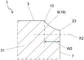
The land surface 9 in the example shown in fig. 5 has a second land surface 19 connected to the first edge 13. Here, the width of the second land surface 19 when viewed from the front side of the first surface 3 is defined as a third width W2. The second land surface 19 may have a portion where the third width W2 narrows as it goes away from the first land surface 17. In the case where the second land surface 19 has the above-described portion, the durability of the insert 1 is higher. In particular, in the case where the second cutting edge 23 is used as the main cutting edge, the durability of the main cutting edge to which a relatively large cutting load is applied is high.
In the case where the second land surface 19 has a portion where the third width W2 narrows with distance from the first land surface 17, the second land surface 19 may further have a portion where the third width W2 is constant.
In order to easily visually understand the change in the third width W2 of the second land surface 19 in the example shown in fig. 5, cross-sectional views are shown in fig. 7, 9, and 10. In each cross section, a third width W2 of the second land surface 19 is shown. W2 shown in fig. 7 is larger than W2 shown in fig. 9, and W2 shown in fig. 9 is larger than W2 shown in fig. 10.
As is apparent from these drawings, in the example shown in fig. 5, the second land surface 19 has a portion in which the third width W2 becomes narrower as it becomes farther from the first land surface 17. The cross section shown in fig. 7 is a cross section at the boundary between the first land surface 17 and the second land surface 19.
As shown in fig. 5, the land surface 9 may further include a third land surface 25 that is disposed along the second edge 15 of the first surface 3 and is connected to the second edge 15. In the example shown in fig. 5, the third cutting edge 27 is disposed as a cutting edge on a ridge line where the third land surface 25 and the third surface 7 intersect.
In the case where the first land surface 17 is viewed from the front side of the first surface 3 as in the example shown in fig. 5, the first width W13 at the end portion on the second land surface 19 side (hereinafter, referred to as the second end portion 17c for convenience) may be wider than the first width W11 at the portion connected to the center of the first corner 11.
In the case where the first land surface 17 has the above-described structure, even when a ridge line intersecting the third surface 7 and the first land surface 17 at a portion from the central portion 17a to the second end portion 17c is used as a cutting edge, the first land surface 17 has high durability and excellent sharpness. That is, the present invention can be used for both a right-hand cutting tool and a left-hand cutting tool. Therefore, the insert 1 is excellent in economical efficiency.
In order to easily visually understand the change in the first width W1 of the first land surface 17 in the example shown in fig. 5, cross-sectional views are shown in fig. 6, 11, and 12. In each cross section, the first width W1 of the first land surface 17 is shown. W13 shown in fig. 12 is larger than W1 shown in fig. 11, and W1 shown in fig. 11 is larger than W11 shown in fig. 6.
As is apparent from these drawings, in the example shown in fig. 5, the first width W13 at the second end 17c is wider than the first width W11 at the portion connected to the center of the first corner 11.
At this time, when the width of the third land surface 25 when viewed from the front side of the first surface 3 is defined as the fourth width W3, the third land surface 25 may have a portion where the fourth width W3 becomes narrower as it becomes farther from the first land surface 17. When the third land surface 25 is configured as described above, the durability of the insert 1 is further enhanced. In particular, in the case where the third cutting edge 27 is used as the main cutting edge, the durability of the main cutting edge to which a relatively large cutting load is applied becomes high.
When viewed from the front side of the first surface 3, the third land surface 25 may have both a portion where the fourth width W3 becomes narrower as it goes away from the first corner 11 and a portion where the fourth width W3 is constant.
Fig. 12 to 14 are cross-sectional views for easy visual understanding of the change in the fourth width W3 of the third land surface 25 in the example shown in fig. 5. In each cross section, a fourth width W3 of the third land surface 25 is shown. W3 shown in fig. 12 is larger than W3 shown in fig. 13, and W3 shown in fig. 13 is larger than W3 shown in fig. 14.
As is apparent from these drawings, in the example shown in fig. 5, the third land surface 25 has a portion in which the fourth width W3 becomes narrower as it becomes farther from the first land surface 17. The cross section shown in fig. 12 is a cross section at the boundary between the first land surface 17 and the second land surface 19.
The shape of the land surface 9 in the cross section orthogonal to the ridge line intersecting the first surface 3 and the land surface 9 is not limited to a specific shape. The shape of the land surface 9 in the cross section may be, for example, a linear shape, or may be a concave shape as shown in fig. 6 to 14. As shown in fig. 6 to 14, when the first land surface 17 is concave, the inclination angle of the land surface 9 is small, and the width of the land surface 9 when viewed from the first surface 3 side in front view is reduced. Therefore, the sharpness of the cutting edge is higher.
The shape of the land surface 9 in the cross section may have a step 9b as shown in fig. 15. In the case where the land surface 9 has the step 9b as shown in fig. 15, the durability of the land surface 9 is further increased.
Examples of the material of the insert 1 include cemented carbide, cermet, ceramic, PCD (polycrystalline diamond), cBN (cubic boron nitride), and the like.
Examples of the composition of the cemented carbide include WC (tungsten carbide) -Co, WC-TiC (titanium carbide) -Co, and WC-TiC-TaC (tantalum carbide) -Co. Here, WC, TiC, and TaC are hard particles, and Co is a binder phase. The cermet is a sintered composite material obtained by compounding a metal into a ceramic component. Specifically, examples of the cermet include compounds containing TiC or TiN (titanium nitride) as a main component. The material of the blade 1 is not limited to the above.
The blade 1 may have only one member made of the material exemplified above, or may have a plurality of members made of the material exemplified above.
For example, as shown in fig. 1, the insert 1 may have a polygonal plate shape as a whole, and may have a body portion 29 and a cutting portion 31. The main body 29 in the example shown in fig. 1 has a substantially polygonal plate shape, and is a concave shape with a partial cutout. The cut portion 31 is joined to the concave portion of the notch by solder or the like.
Here, as shown in fig. 1, the first corner 11, the first side 13, and the second side 15 may be located at the cutting portion 31. In fig. 1, the cut portion 31 is hatched with diagonal lines for easy visual understanding.
The cutting portion 31 may be made of a relatively hard material such as PCD or cBN, for example, and the body portion 29 may be made of cemented carbide, cermet, or ceramic, for example. When the main body 21 and the cutting portion 23 are made of the above-described material, the insert 1 can be manufactured at low cost. In addition, the insert 1 has high durability against cutting loads. The hardness of the body portion 29 and the hardness of the cutting portion 31 may be evaluated by measuring the vickers hardness of each portion.
The insert 1 may have only the cutting portion 31 and the body portion 29, but may also have a coating layer that covers the surface of the cutting portion 31 and the body portion 29, in addition to the portions thereof. The coating layer may cover the entire surface of the base body including the cutting portion 31 and the body portion 29, or may cover only a part of the surface of the base body.
Examples of the material of the coating layer include aluminum oxide (alumina) and titanium carbide, nitride, oxide, oxycarbide, oxynitride, carbonitride, oxycarbonitride, and the like. The coating layer may contain only one of the above materials, or may contain a plurality of the above materials.
The cover layer may be formed of only one layer, or may be formed by stacking a plurality of layers. The material of the cover layer is not limited to these. The cover layer can be disposed on the substrate by using, for example, a Chemical Vapor Deposition (CVD) method or a Physical Vapor Deposition (PVD) method.
As shown in fig. 1, the blade 1 may have a through hole 33. The through-holes 33 in the embodiment are formed from the first face 3 to the second face 5, and are open in these faces. The through hole 33 may extend along a central axis X1 passing through the center of the first face 3 and the center of the second face 5. The through-hole 33 may be used for mounting a fixing screw or a clamping member when holding the insert 1 to the holder. The through-holes 33 are not problematic even if they are open in regions of the third surface 7 located on opposite sides of each other.
< cutting tool >
Next, the cutting tool 101 of the embodiment will be described with reference to the drawings.
As shown in fig. 16 and 17, the cutting tool 101 of the embodiment includes: a tool holder 105 having a tool pocket 103 (insert pocket) on a leading end side; and the blade 1 described above, which is located in the pocket 103. In the cutting tool 101 of the embodiment, the insert 1 is attached so that the ridge line protrudes from the distal end of the holder 105.
The tool holder 105 is formed in an elongated extending rod shape. Further, one pocket 103 is provided on the tip side of the tool holder 105. The pocket 103 is a portion to which the insert 1 is attached, and opens to the front end surface of the holder 105. At this time, the pocket 103 also opens to the side surface of the holder 105, so that the insert 1 can be easily attached. Specifically, the pocket 103 has a seating surface parallel to the lower surface of the tool holder 105, and a constraining side surface inclined with respect to the seating surface.
The insert 1 is located in the pocket 103. In this case, the lower surface of the insert 1 may be in direct contact with the pocket 103, or the sheet may be sandwiched between the insert 1 and the pocket 103.
The insert 1 is attached in such a manner that a portion of the ridge line, which serves as a cutting edge, protrudes outward from the holder 105. In an embodiment, the insert 1 is mounted to the holder 105 by means of a fixing screw 107. That is, the insert 1 is attached to the holder 105 by inserting the fixing screw 107 into the through hole of the insert 1, inserting the tip of the fixing screw 107 into the screw hole formed in the insert pocket 103, and screwing the screw portions together.
Steel, cast iron, or the like can be used as the tool holder 105. In particular, steel may be used for these members from the viewpoint of improving the toughness of the tool holder 103.
In the embodiment, a cutting tool used in so-called turning is exemplified. Examples of the turning include inner diameter machining, outer diameter machining, and grooving machining. The cutting tool is not limited to a cutting tool used for turning. For example, the insert 1 of the above-described embodiment may be used for a cutting tool used for rotary cutting.
< method for producing machined article >
Next, a method for manufacturing a machined product according to an embodiment will be described with reference to the drawings.
The machined product is produced by machining the workpiece 201. The method for producing a machined product according to the embodiment includes the following steps. Namely, the method comprises the following steps:
(1) rotating the workpiece 201;
(2) bringing the ridge line in the cutting tool 101 represented by the above embodiment into contact with the rotating workpiece 201; and
(3) causing the cutting tool 101 to move away from the workpiece 201.
More specifically, first, as shown in fig. 18, the workpiece 201 is rotated about the axis O1, and the cutting tool 101 is relatively brought close to the workpiece 201. Next, as shown in fig. 19, the ridge line (cutting edge) of the cutting tool 101 is brought into contact with the workpiece 201, thereby cutting the workpiece 201. Then, as shown in fig. 20, the cutting tool 101 is relatively moved away from the workpiece 201.
In the embodiment, the cutting tool 101 is moved in the Y1 direction while the axis O1 is fixed and the workpiece 201 is rotated, so that the cutting tool 101 approaches the workpiece 201. In fig. 19, the cutting edge of the insert is brought into contact with the rotating workpiece 201 to cut the workpiece 201. In fig. 20, the cutting tool 101 is moved in the Y2 direction while the workpiece 201 is rotated, whereby the cutting tool 101 is moved away from the workpiece 201.
In the cutting process in the manufacturing method according to the embodiment, the cutting tool 101 is moved in each step to bring the cutting tool 101 into contact with the workpiece 201 or to separate the cutting tool 101 from the workpiece 201, but the present invention is not limited to this embodiment.
For example, in the step (1), the workpiece 201 may be brought close to the cutting tool 101. Similarly, in the step (3), the workpiece 201 may be separated from the cutting tool 101. When the cutting process is continued, the step of bringing the cutting edge of the insert into contact with the workpiece 201 at different positions while maintaining the state in which the workpiece 201 is rotated may be repeated.
Representative examples of the material of the workpiece 201 include carbon steel, alloy steel, stainless steel, cast iron, and nonferrous metals.
Description of reference numerals:
1. cutting blade
3. first side
5. second face
7. third surface
9. land surface
11. first corner
13. first side
15. second side
17. first land portion
17 a. center part
17 b. first end
17 c. second end
19. second land surface
21. first cutting edge
23. second cutting edge
25. third land surface
27. third cutting edge
29. main body part
31. cutting part
33. through hole
101. cutting tool
103. knife groove
105. tool post
107. set screw
201. the workpiece.