CN110934636B - Flow regulating assembly and flow-adjustable flexible cryoprobe - Google Patents
Flow regulating assembly and flow-adjustable flexible cryoprobe Download PDFInfo
- Publication number
- CN110934636B CN110934636B CN202010111100.7A CN202010111100A CN110934636B CN 110934636 B CN110934636 B CN 110934636B CN 202010111100 A CN202010111100 A CN 202010111100A CN 110934636 B CN110934636 B CN 110934636B
- Authority
- CN
- China
- Prior art keywords
- air outlet
- flow
- mandrel
- needle
- assembly
- Prior art date
- Legal status (The legal status is an assumption and is not a legal conclusion. Google has not performed a legal analysis and makes no representation as to the accuracy of the status listed.)
- Active
Links
Images




Classifications
-
- A—HUMAN NECESSITIES
- A61—MEDICAL OR VETERINARY SCIENCE; HYGIENE
- A61B—DIAGNOSIS; SURGERY; IDENTIFICATION
- A61B18/00—Surgical instruments, devices or methods for transferring non-mechanical forms of energy to or from the body
- A61B18/02—Surgical instruments, devices or methods for transferring non-mechanical forms of energy to or from the body by cooling, e.g. cryogenic techniques
- A61B18/0218—Surgical instruments, devices or methods for transferring non-mechanical forms of energy to or from the body by cooling, e.g. cryogenic techniques with open-end cryogenic probe, e.g. for spraying fluid directly on tissue or via a tissue-contacting porous tip
-
- A—HUMAN NECESSITIES
- A61—MEDICAL OR VETERINARY SCIENCE; HYGIENE
- A61B—DIAGNOSIS; SURGERY; IDENTIFICATION
- A61B18/00—Surgical instruments, devices or methods for transferring non-mechanical forms of energy to or from the body
- A61B18/02—Surgical instruments, devices or methods for transferring non-mechanical forms of energy to or from the body by cooling, e.g. cryogenic techniques
-
- A—HUMAN NECESSITIES
- A61—MEDICAL OR VETERINARY SCIENCE; HYGIENE
- A61B—DIAGNOSIS; SURGERY; IDENTIFICATION
- A61B17/00—Surgical instruments, devices or methods
- A61B2017/00367—Details of actuation of instruments, e.g. relations between pushing buttons, or the like, and activation of the tool, working tip, or the like
-
- A—HUMAN NECESSITIES
- A61—MEDICAL OR VETERINARY SCIENCE; HYGIENE
- A61B—DIAGNOSIS; SURGERY; IDENTIFICATION
- A61B18/00—Surgical instruments, devices or methods for transferring non-mechanical forms of energy to or from the body
- A61B2018/00053—Mechanical features of the instrument of device
- A61B2018/00059—Material properties
- A61B2018/00089—Thermal conductivity
- A61B2018/00101—Thermal conductivity low, i.e. thermally insulating
-
- A—HUMAN NECESSITIES
- A61—MEDICAL OR VETERINARY SCIENCE; HYGIENE
- A61B—DIAGNOSIS; SURGERY; IDENTIFICATION
- A61B18/00—Surgical instruments, devices or methods for transferring non-mechanical forms of energy to or from the body
- A61B2018/00571—Surgical instruments, devices or methods for transferring non-mechanical forms of energy to or from the body for achieving a particular surgical effect
- A61B2018/00577—Ablation
-
- A—HUMAN NECESSITIES
- A61—MEDICAL OR VETERINARY SCIENCE; HYGIENE
- A61B—DIAGNOSIS; SURGERY; IDENTIFICATION
- A61B18/00—Surgical instruments, devices or methods for transferring non-mechanical forms of energy to or from the body
- A61B2018/00636—Sensing and controlling the application of energy
- A61B2018/00696—Controlled or regulated parameters
- A61B2018/00744—Fluid flow
-
- A—HUMAN NECESSITIES
- A61—MEDICAL OR VETERINARY SCIENCE; HYGIENE
- A61B—DIAGNOSIS; SURGERY; IDENTIFICATION
- A61B18/00—Surgical instruments, devices or methods for transferring non-mechanical forms of energy to or from the body
- A61B18/02—Surgical instruments, devices or methods for transferring non-mechanical forms of energy to or from the body by cooling, e.g. cryogenic techniques
- A61B2018/0212—Surgical instruments, devices or methods for transferring non-mechanical forms of energy to or from the body by cooling, e.g. cryogenic techniques using an instrument inserted into a body lumen, e.g. catheter
-
- A—HUMAN NECESSITIES
- A61—MEDICAL OR VETERINARY SCIENCE; HYGIENE
- A61B—DIAGNOSIS; SURGERY; IDENTIFICATION
- A61B18/00—Surgical instruments, devices or methods for transferring non-mechanical forms of energy to or from the body
- A61B18/02—Surgical instruments, devices or methods for transferring non-mechanical forms of energy to or from the body by cooling, e.g. cryogenic techniques
- A61B2018/0231—Characteristics of handpieces or probes
- A61B2018/0262—Characteristics of handpieces or probes using a circulating cryogenic fluid
-
- A—HUMAN NECESSITIES
- A61—MEDICAL OR VETERINARY SCIENCE; HYGIENE
- A61B—DIAGNOSIS; SURGERY; IDENTIFICATION
- A61B18/00—Surgical instruments, devices or methods for transferring non-mechanical forms of energy to or from the body
- A61B18/02—Surgical instruments, devices or methods for transferring non-mechanical forms of energy to or from the body by cooling, e.g. cryogenic techniques
- A61B2018/0231—Characteristics of handpieces or probes
- A61B2018/0262—Characteristics of handpieces or probes using a circulating cryogenic fluid
- A61B2018/0268—Characteristics of handpieces or probes using a circulating cryogenic fluid with restriction of flow
-
- A—HUMAN NECESSITIES
- A61—MEDICAL OR VETERINARY SCIENCE; HYGIENE
- A61B—DIAGNOSIS; SURGERY; IDENTIFICATION
- A61B18/00—Surgical instruments, devices or methods for transferring non-mechanical forms of energy to or from the body
- A61B18/02—Surgical instruments, devices or methods for transferring non-mechanical forms of energy to or from the body by cooling, e.g. cryogenic techniques
- A61B2018/0293—Surgical instruments, devices or methods for transferring non-mechanical forms of energy to or from the body by cooling, e.g. cryogenic techniques using an instrument interstitially inserted into the body, e.g. needle
Landscapes
- Health & Medical Sciences (AREA)
- Surgery (AREA)
- Life Sciences & Earth Sciences (AREA)
- Nuclear Medicine, Radiotherapy & Molecular Imaging (AREA)
- Medical Informatics (AREA)
- General Health & Medical Sciences (AREA)
- Biomedical Technology (AREA)
- Heart & Thoracic Surgery (AREA)
- Otolaryngology (AREA)
- Molecular Biology (AREA)
- Animal Behavior & Ethology (AREA)
- Engineering & Computer Science (AREA)
- Public Health (AREA)
- Veterinary Medicine (AREA)
- Media Introduction/Drainage Providing Device (AREA)
- Flow Control (AREA)
- Safety Valves (AREA)
- Reciprocating Pumps (AREA)
Abstract
本发明提供了一种流量调节组件,包括一芯轴,芯轴内设置有调节腔;芯轴的第一端部设置有大出气孔,芯轴的侧壁设置有小出气孔,大出气孔的内径小于调节腔的内径;芯轴的第二端部与一J‑T槽的前端连接,J‑T槽的后端与一旁通管连接;调节腔内设置有一密封件,密封件的外径小于或等于调节腔的内径,大于大出气孔的内径;密封件与一牵引件的一端连接,牵引件的另一端通过旁通管引出;其中,密封件在牵引件的作用下在调节腔内轴向运动,通过调节密封件的位置以改变有效出气孔的数量。以解决相关技术中流量调节方法均通过主机端内部的控制实现,容易出现流量不稳定、冷量损失严重以及工作压力可调节的范围过窄,对应可调节流量范围过窄的问题。

The invention provides a flow regulating assembly, which comprises a mandrel, a regulating cavity is arranged in the mandrel; the first end of the mandrel is provided with a large air outlet, the side wall of the mandrel is provided with a small air outlet, and the large air outlet is provided The inner diameter is smaller than the inner diameter of the adjustment cavity; the second end of the mandrel is connected with the front end of a J-T slot, and the rear end of the J-T slot is connected with a bypass pipe; a seal is arranged in the adjustment cavity, and the outer part of the seal is The diameter is smaller than or equal to the inner diameter of the adjustment cavity and larger than the inner diameter of the large air outlet; the seal is connected to one end of a pulling piece, and the other end of the pulling piece is drawn out through the bypass pipe; wherein, the sealing piece is in the adjustment cavity under the action of the pulling piece Inner axial movement, by adjusting the position of the seal to change the number of effective air outlets. In order to solve the problem that the flow adjustment method in the related art is realized by the internal control of the host, it is prone to unstable flow, serious cooling loss, and the adjustable range of working pressure is too narrow, corresponding to the problem that the adjustable flow range is too narrow.
Description
技术领域technical field
本发明涉及医疗器械领域,尤其涉及流量调节组件以及流量可调节的柔性冷冻探针。The invention relates to the field of medical instruments, in particular to a flow regulating assembly and a flexible cryoprobe with adjustable flow.
背景技术Background technique
冷冻治疗包括冷冻消融和冷冻粘连两大类:冷冻消融需将组织灭活,产生不可逆的损伤,常用于肿瘤的消融治疗;冷冻粘连只需通过冷冻粘住组织将其取出即可,冷冻活检、冻切和异物提取都属于冷冻粘连。Cryotherapy includes two categories: cryoablation and cryoadhesion: cryoablation requires tissue inactivation, resulting in irreversible damage, and is often used in tumor ablation; cryoadhesion only needs to be removed by freezing the adherent tissue, cryobiopsy, Frozen cutting and foreign body extraction are classified as cryoadhesion.
冷冻治疗在临床应用中,有很多需要调节流量的情形,比如冷冻功率调节,冷冻功率调节即流量调节,功率或流量越低冰球生长速率越慢,对于已经达到所需冰球大小但需延长冷冻时间的情形,可通过降低功率来停止冰球继续增长。此外,针头降温过程所需的流量高于降温后维持低温所需的流量,因此当针头降至最低温后,将流量降低至维持低温的最小值,可在基本不影响冷冻性能的前提下大幅降低气体的消耗量,达到省气的目的。In the clinical application of cryotherapy, there are many situations in which it is necessary to adjust the flow rate, such as the adjustment of freezing power. , you can stop the puck from continuing to grow by reducing the power. In addition, the flow rate required for the needle cooling process is higher than the flow rate required to maintain a low temperature after cooling. Therefore, when the needle drops to the lowest temperature, reducing the flow rate to the minimum value for maintaining the low temperature can greatly reduce the freezing performance without affecting the freezing performance. Reduce gas consumption and achieve the purpose of saving gas.
相关技术中,流量调节方法均通过主机端内部的控制实现,如进气阀的开断控制、流量控制器或减压阀调节,通常会造成在探针端延迟响应,还可能会出现流量不稳定、冷量损失严重,以及工作压力可调节的范围过窄,对应可调节流量范围过窄的问题。In the related art, the flow adjustment methods are all realized through the internal control of the host, such as the on-off control of the intake valve, the adjustment of the flow controller or the pressure reducing valve, which usually results in a delayed response at the probe end, and may also cause flow insufficiency. Stability, serious loss of cooling capacity, and too narrow adjustable range of working pressure, corresponding to the problem that the adjustable flow range is too narrow.
发明内容SUMMARY OF THE INVENTION
本发明提供了流量调节组件以及流量可调节的柔性冷冻探针,以解决相关技术中出现流量不稳定、冷量损失严重,以及工作压力可调节的范围过窄,对应可调节流量范围过窄的问题。The present invention provides a flow regulating assembly and a flexible freezing probe with adjustable flow, so as to solve the problems of unstable flow, serious loss of cooling capacity, and too narrow adjustable range of working pressure in the related art, corresponding to the problem that the range of adjustable flow is too narrow. question.
根据本发明的第一方面,提供了一种流量调节组件,所述流量调节组件包括芯轴,所述芯轴内设置有调节腔;According to a first aspect of the present invention, a flow adjustment assembly is provided, the flow adjustment assembly includes a mandrel, and an adjustment cavity is provided in the mandrel;
所述芯轴的第一端部设置有大出气孔,所述芯轴的侧壁设置有小出气孔,所述大出气孔的内径小于所述调节腔的内径;The first end of the mandrel is provided with a large air outlet, the side wall of the mandrel is provided with a small air outlet, and the inner diameter of the large air outlet is smaller than the inner diameter of the adjustment cavity;
所述芯轴的第二端部与一J-T槽的前端连接,所述J-T槽的后端与一旁通管连接;The second end of the mandrel is connected with the front end of a J-T slot, and the rear end of the J-T slot is connected with a bypass pipe;
所述调节腔内设置有一密封件,所述密封件的外径小于或等于所述调节腔的内径,大于所述大出气孔的内径;A sealing member is arranged in the adjustment cavity, and the outer diameter of the sealing member is smaller than or equal to the inner diameter of the adjustment cavity, and is larger than the inner diameter of the large air outlet;
所述密封件与一牵引件的一端连接,所述牵引件的另一端通过所述旁通管引出;The sealing element is connected with one end of a pulling element, and the other end of the pulling element is led out through the bypass pipe;
所述旁通管末端设置有密封组件,所述密封组件包括密封圈,所述密封圈的内径与所述牵引件的外径相匹配,以供所述牵引件通过;The end of the bypass pipe is provided with a sealing assembly, and the sealing assembly includes a sealing ring, the inner diameter of the sealing ring is matched with the outer diameter of the pulling member, so that the pulling member can pass;
其中,所述密封件在所述牵引件的作用下在所述调节腔内轴向运动,通过调节所述密封件的位置以改变所述大出气孔与所述小出气孔中连通至所述旁通管的有效出气孔的数量。Wherein, the sealing member moves axially in the adjusting cavity under the action of the pulling member, and the communication between the large air outlet hole and the small air outlet hole is changed by adjusting the position of the sealing member. The number of effective vent holes for the bypass pipe.
可选地,所述密封件的外径小于所述调节腔的内径,所述小出气孔的数量至少为一个;Optionally, the outer diameter of the sealing member is smaller than the inner diameter of the adjustment cavity, and the number of the small air outlet holes is at least one;
其中,所述密封件在所述芯轴的第一端部的大出气孔处时,所述大出气孔封闭,所述小出气孔连通至所述旁通管,以作为所述有效出气孔进行出气;当所述密封件在所述牵引件的牵引下向所述芯轴的第二端部移动后,所述大出气孔和所述小出气孔均连通至所述旁通管,以作为所述有效出气孔进行出气。Wherein, when the seal is at the large air outlet of the first end of the mandrel, the large air outlet is closed, and the small air outlet is connected to the bypass pipe to serve as the effective air outlet Carry out air outlet; when the sealing member moves to the second end of the mandrel under the pulling of the pulling member, the large air outlet hole and the small air outlet hole are both connected to the bypass pipe, so as to The air is discharged as the effective air outlet.
可选地,所述密封件的外径等于所述调节腔的内径,所述小出气孔的数量至少为两排,每排小出气孔的数量为至少一个,至少两组小出气孔沿所述芯轴的轴向分布;Optionally, the outer diameter of the sealing member is equal to the inner diameter of the adjustment cavity, the number of the small air outlets is at least two rows, the number of small air outlets in each row is at least one, and at least two groups of small air outlets are arranged along each other. The axial distribution of the mandrel;
其中,所述密封件在所述芯轴的大出气孔处时,每个所述小出气孔均连通至所述旁通管,以作为所述有效出气孔;当所述密封件在所述牵引件的作用下向所述芯轴的第二端部移动时,连通至所述旁通管,以作为所述有效出气孔的小出气孔的数量减少。Wherein, when the seal is at the large air outlet of the mandrel, each of the small air outlets is connected to the bypass pipe to serve as the effective air outlet; when the seal is at the When moving toward the second end of the mandrel under the action of the pulling member, it is communicated with the bypass pipe, so that the number of small air outlets serving as the effective air outlets is reduced.
可选地,所述密封件还包括密封圈压件,所述密封圈压件套设于所述旁通管末端,所述密封圈沿所述旁通管的长度方向夹持于所述密封圈压件与所述旁通管末端之间,所述密封圈压件设有用于供所述牵引件穿过的通孔。Optionally, the sealing member further includes a sealing ring pressing member, the sealing ring pressing member is sleeved on the end of the bypass pipe, and the sealing ring is clamped to the sealing ring along the length direction of the bypass pipe Between the ring pressing member and the end of the bypass pipe, the sealing ring pressing member is provided with a through hole for the pulling member to pass through.
根据本发明的第二方面,提供了一种流量可调节的柔性冷冻探针,所述柔性冷冻探针包括前述各实施例中所述的流量调节组件,所述柔性冷冻探针还包括:针头导管部件、手柄部件和延长管部件,所述延长管部件包括进气管、回气管以及调节管;According to a second aspect of the present invention, a flow-adjustable flexible cryoprobe is provided, the flexible cryoprobe includes the flow adjustment assembly described in the foregoing embodiments, and the flexible cryoprobe further includes: a needle a catheter part, a handle part and an extension pipe part, the extension pipe part includes an air intake pipe, a return air pipe and an adjustment pipe;
所述流量调节组件设置在所述针头导管部件的内部,所述针头导管部件与所述手柄部件连接;the flow regulating assembly is arranged inside the needle catheter part, and the needle catheter part is connected with the handle part;
所述进气管与所述流量调节组件中的旁通管连接,所述调节腔中的气体通过所述回气管排出;the air inlet pipe is connected with the bypass pipe in the flow regulating assembly, and the gas in the regulating cavity is discharged through the gas return pipe;
所述调节管用于直接或间接调节所述调节腔中密封件的轴向位置。The adjustment tube is used to directly or indirectly adjust the axial position of the seal in the adjustment cavity.
可选地,所述针头导管部件包含针尖、针头、内层管组件和外层管组件;Optionally, the needle catheter component comprises a needle tip, a needle, an inner tube assembly and an outer tube assembly;
所述针头包含针头前段和针头后段,所述针尖设置在所述针头的前方端部,所述针头后段与所述内层管组件和所述外层管组件固定连接。The needle includes a front section of the needle and a rear section of the needle, the needle tip is disposed at the front end of the needle, and the rear section of the needle is fixedly connected with the inner tube assembly and the outer tube assembly.
可选地,所述内层管组件和所述外层管组件之间设置有隔热层,所述隔热层为隔热材料或真空层。Optionally, a thermal insulation layer is provided between the inner tube assembly and the outer tube assembly, and the thermal insulation layer is a thermal insulation material or a vacuum layer.
可选地,所述调节腔置于所述针头前段的内部,所述J-T槽设置在所述内层管组件的内部,所述针头中的气体从所述内层管组件和所述J-T槽之间的间隙返回。Optionally, the adjustment cavity is placed inside the front section of the needle, the J-T groove is disposed inside the inner tube assembly, and the gas in the needle is removed from the inner tube assembly and the J-T groove. gap between returns.
可选地,所述手柄上设置有拨杆和连接件,所述连接件的一端与所述牵引件连接,所述连接件的另一端与所述拨杆连接,通过所述拨杆调节所述调节腔中密封件的轴向位置。Optionally, the handle is provided with a lever and a connecting piece, one end of the connecting piece is connected with the traction piece, and the other end of the connecting piece is connected with the lever, and the lever is used to adjust the lever. the axial position of the seal in the adjustment chamber.
本发明提供的流量调节组件,在芯轴上设置大出气孔和小出气孔,在调节腔内设置密封件,该密封件与一牵引件穿过旁通管与外部连接,密封件在牵引件的带动下,通过改变密封件的位置改变有效出气孔的数量,从而实现多档位流量调节功能。In the flow adjustment assembly provided by the present invention, a large air outlet hole and a small air outlet hole are arranged on the mandrel, and a sealing member is arranged in the adjustment cavity. Driven by the change of the position of the seal, the number of effective air outlets can be changed, so as to realize the multi-speed flow adjustment function.
附图说明Description of drawings
为了更清楚地说明本发明实施例或现有技术中的技术方案,下面将对实施例或现有技术描述中所需要使用的附图作简单地介绍,显而易见地,下面描述中的附图仅仅是本发明的一些实施例,对于本领域普通技术人员来讲,在不付出创造性劳动性的前提下,还可以根据这些附图获得其他的附图。In order to explain the embodiments of the present invention or the technical solutions in the prior art more clearly, the following briefly introduces the accompanying drawings that need to be used in the description of the embodiments or the prior art. Obviously, the accompanying drawings in the following description are only These are some embodiments of the present invention, and for those of ordinary skill in the art, other drawings can also be obtained from these drawings without any creative effort.
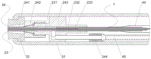
图1是本发明一实施例中流量调节组件的轴向密封结构示意图;1 is a schematic diagram of an axial sealing structure of a flow regulating assembly in an embodiment of the present invention;
图2是本发明一实施例中流量调节组件的径向密封结构示意图;2 is a schematic diagram of a radial sealing structure of a flow regulating assembly in an embodiment of the present invention;
图3是本发明一实施例中流量调节组件的高流量状态的结构示意图;3 is a schematic structural diagram of a high flow state of a flow regulating assembly in an embodiment of the present invention;
图4是本发明一实施例中流量调节组件的低流量状态的结构示意图;4 is a schematic structural diagram of a low flow state of a flow regulating assembly in an embodiment of the present invention;
图5是本发明一实施例中流量可调节的柔性冷冻探针的结构示意图;5 is a schematic structural diagram of a flexible cryoprobe with adjustable flow in an embodiment of the present invention;
图6是本发明一实施例中流量可调节的柔性冷冻探针冷冻消融模式下的针头部位的结构示意图;6 is a schematic structural diagram of a needle portion in a cryoablation mode of a flexible cryoprobe with adjustable flow according to an embodiment of the present invention;
图7是本发明一实施例中流量可调节的柔性冷冻探针的手柄前段结构示意图;7 is a schematic structural diagram of the front section of the handle of the flexible cryoprobe with adjustable flow according to an embodiment of the present invention;
图8是本发明一实施例中流量可调节的柔性冷冻探针手柄后段的结构示意图;8 is a schematic structural diagram of the rear section of the flexible cryoprobe handle with adjustable flow according to an embodiment of the present invention;
图9是本发明一实施例中流量可调节的柔性冷冻探针冷冻粘连模式下的针头部位的结构示意图;9 is a schematic structural diagram of a needle portion in a cryo-adhesion mode of a flexible cryoprobe with adjustable flow according to an embodiment of the present invention;
图10是本发明一实施例中流量可调节的柔性冷冻探针手柄后段的结构示意图。10 is a schematic structural diagram of the rear section of the flexible cryoprobe handle with adjustable flow in an embodiment of the present invention.
附图标记说明:Description of reference numbers:
1-流量调节组件;1-flow adjustment components;
11-调节腔;11- Adjustment cavity;
111-大出气孔;111-large vent;
112-小出气孔;112- small air outlet;
113-密封面;113 - sealing surface;
12-密封件;12-seal;
121-密封球;121 - sealing ball;
13-J-T槽;13-J-T slot;
14-旁通管;14-bypass pipe;
141-密封圈;141 - sealing ring;
142-密封圈压件;142 - Sealing ring pressure piece;
15-细拉丝;15-fine wire drawing;
16-粗拉丝;16-coarse wire drawing;
2-针头导管部件;2- Needle catheter part;
21-针尖;21 - needle tip;
22-针头;22 - Needle;
221-针头前段;221 - the front section of the needle;
222-针头后段;222 - the posterior segment of the needle;
23-内层管组件;23 - inner tube assembly;
231-内层柔性导管;231 - Inner flexible conduit;
232-挤压管;232 - extruded tube;
233-回气连接管;233- return air connection pipe;
24-外层管组件;24 - Outer tube assembly;
241-外层柔性导管;241 - Outer layer flexible conduit;
242-快拧螺帽;242-quick screw cap;
243-真空腔体;243 - vacuum chamber;
244-宝塔接头;244 - Pagoda joint;
3-手柄部件;3-handle parts;
31-前手柄;31 - front handle;
311-滑动槽;311 - sliding groove;
312-限位孔;312-limit hole;
32-后手柄;32 - rear handle;
33-护弯管;33-Bend pipe;
34-按钮组件;34-button component;
341-按钮盒;341 - button box;
342-滑块;342-slider;
3421-拨动槽;3421 - toggle slot;
3422-连杆孔;3422 - connecting rod hole;
343-按钮;343 - button;
344-连杆;344 - connecting rod;
345-弹簧;345 - spring;
346-拨动开关;346 - toggle switch;
347-开关导线;347 - switch wire;
4-延长管部件;4-Extension tube parts;
41-延长管;41 - extension tube;
42-进气管;42 - intake pipe;
43-回气管;43-return trachea;
44 -分流管;44 - shunt;
441-引出孔;441-outlet hole;
45-真空软管;45 - vacuum hose;
具体实施方式Detailed ways
下面将结合本发明实施例中的附图,对本发明实施例中的技术方案进行清楚、完整地描述,显然,所描述的实施例仅仅是本发明一部分实施例,而不是全部的实施例。基于本发明中的实施例,本领域普通技术人员在没有做出创造性劳动前提下所获得的所有其他实施例,都属于本发明保护的范围。The technical solutions in the embodiments of the present invention will be clearly and completely described below with reference to the accompanying drawings in the embodiments of the present invention. Obviously, the described embodiments are only a part of the embodiments of the present invention, but not all of the embodiments. Based on the embodiments of the present invention, all other embodiments obtained by those of ordinary skill in the art without creative efforts shall fall within the protection scope of the present invention.
本发明的说明书和权利要求书及上述附图中的术语“第一”、“第二”、“第三”“第四”等(如果存在)是用于区别类似的对象,而不必用于描述特定的顺序或先后次序。应该理解这样使用的数据在适当情况下可以互换,以便这里描述的本发明的实施例能够以除了在这里图示或描述的那些以外的顺序实施。此外,术语“包括”和“具有”以及他们的任何变形,意图在于覆盖不排他的包含,例如,包含了一系列步骤或单元的过程、方法、系统、产品或设备不必限于清楚地列出的那些步骤或单元,而是可包括没有清楚地列出的或对于这些过程、方法、产品或设备固有的其它步骤或单元。The terms "first", "second", "third", "fourth", etc. (if any) in the description and claims of the present invention and the above-mentioned drawings are used to distinguish similar objects and are not necessarily used to Describe a particular order or sequence. It is to be understood that the data so used may be interchanged under appropriate circumstances such that the embodiments of the invention described herein can be practiced in sequences other than those illustrated or described herein. Furthermore, the terms "comprising" and "having" and any variations thereof, are intended to cover non-exclusive inclusion, for example, a process, method, system, product or device comprising a series of steps or units is not necessarily limited to those expressly listed Rather, those steps or units may include other steps or units not expressly listed or inherent to these processes, methods, products or devices.
下面以具体地实施例对本发明的技术方案进行详细说明。下面这几个具体的实施例可以相互结合,对于相同或相似的概念或过程可能在某些实施例不再赘述。The technical solutions of the present invention will be described in detail below with specific examples. The following specific embodiments may be combined with each other, and the same or similar concepts or processes may not be repeated in some embodiments.
现有的冷冻粘连技术,一般只用于自然腔道内的冷冻活检、冻切和异物提取,由于其温度不够低、冰球较小,无法有效实现消融治疗。若对现有的冷冻粘连产品通入氮气或氩气等消融用气体,则由于产品本身的流量限制,无法达到较低温度和较大冷冻范围。现有的冷冻消融产品也可以通过一定手段实现冷冻粘连,比如直接通入二氧化碳或一氧化二氮,但这种方法会浪费大量的气体,且回气中绝大多数的冷量都直接排空了,造成排气口喷射或堆积出大量液态或固态的二氧化碳或一氧化二氮,此外,这种方法若应用于经自然腔道的冷冻消融产品中,回气大量富余的冷量会导致柔性导管段变硬,这样一来,粘住组织的针头将无法顺利地从弯曲的腔道或内窥镜钳道中取出。Existing cryoadhesion technology is generally only used for cryobiopsy, cryosection and foreign body extraction in natural cavities. Because its temperature is not low enough and the ice ball is small, it cannot effectively achieve ablation therapy. If an ablation gas such as nitrogen or argon is introduced into the existing frozen adhesion product, the lower temperature and the larger freezing range cannot be achieved due to the flow limitation of the product itself. Existing cryoablation products can also achieve cryo-adhesion by certain means, such as direct introduction of carbon dioxide or nitrous oxide, but this method will waste a lot of gas, and most of the cold energy in the return air is directly evacuated , causing a large amount of liquid or solid carbon dioxide or nitrous oxide to be ejected or accumulated at the exhaust port. In addition, if this method is applied to cryoablation products through natural orifices, a large amount of excess cold energy in the return air will lead to flexibility. The catheter segment becomes rigid so that the needle sticking to the tissue will not be able to be easily removed from the curved lumen or endoscopic forceps.
本发明提供了一种流量调节组件,该流量调节组件包括芯轴,芯轴内部为中空结构,该中空结构为导通气体的调节腔。The present invention provides a flow regulating assembly, which comprises a mandrel, the interior of the mandrel is a hollow structure, and the hollow structure is a regulating cavity for conducting gas.
芯轴的第一端部设置有大出气孔,芯轴的侧壁设置有小出气孔,大出气孔的内径小于调节腔的内径。The first end of the mandrel is provided with a large air outlet, the side wall of the mandrel is provided with a small air outlet, and the inner diameter of the large air outlet is smaller than the inner diameter of the adjustment cavity.
其中的大出气孔、小出气孔,可理解为大出气孔的孔径大于小出气孔,而非特指某尺寸的孔,故而,任意取值的孔径,只要满足大出气孔的孔径大于小出气孔,均不脱离以上描述。Among them, the large vent hole and the small vent hole can be understood as the pore size of the large vent hole is larger than that of the small vent hole, rather than the hole of a certain size. , without departing from the above description.
示例性的,芯轴为内径均匀的管状结构,在芯轴的第一端部设置一具有中间通孔的环状结构,该环状结构固定设置在芯轴的第一端部时,形成内径小于芯轴内径的大出气孔。Exemplarily, the mandrel is a tubular structure with a uniform inner diameter, and an annular structure with a central through hole is disposed at the first end of the mandrel. When the annular structure is fixedly disposed on the first end of the mandrel, the inner diameter is formed. Large vent hole smaller than the inner diameter of the mandrel.
小出气孔设置在芯轴的侧壁,其中,小出气孔的数量可以是一个,也可以是多个。当小出气孔的数量是多个时,多个小出气孔的位置设置在不同的轴向位置,在相同的轴向位置处,可以在不同径向位置处设置不同小出气孔。此外,各小出气孔的孔径和尺寸可以是相同的,同时,也不排除不相同的实施方式。The small air outlet holes are arranged on the side wall of the mandrel, and the number of the small air outlet holes can be one or more. When the number of the small air outlet holes is multiple, the positions of the plurality of small air outlet holes are arranged at different axial positions, and at the same axial position, different small air outlet holes can be arranged at different radial positions. In addition, the pore size and size of each small air outlet may be the same, and at the same time, different embodiments are not excluded.
芯轴的第二端部与一J-T槽的前端连接,J-T槽的后端与一旁通管连接。示例性的,J-T槽是柔性软管,材质可以是金属或其他耐低温的柔性管。所述大出气孔与所述小出气孔沿所述芯轴的轴向位于所述旁通管的同一侧。The second end of the mandrel is connected with the front end of a J-T slot, and the rear end of the J-T slot is connected with a bypass pipe. Exemplarily, the J-T groove is a flexible hose, and the material can be metal or other low-temperature-resistant flexible hoses. The large air outlet and the small air outlet are located on the same side of the bypass pipe along the axial direction of the mandrel.
调节腔内设置有一密封件,该密封件的外径小于或等于调节腔的内径,大于大出气孔的内径;密封件能够在调节腔内进行轴向运动,通过调节密封件的位置以改变所述大出气孔与所述小出气孔中有效出气孔的数量。其中,有效出气孔为无密封件封堵、能够使气体通过的出气孔。A seal is arranged in the adjustment cavity, and the outer diameter of the seal is smaller than or equal to the inner diameter of the adjustment cavity and larger than the inner diameter of the large air outlet; the seal can move axially in the adjustment cavity, and the position of the seal can be adjusted to change the position of the seal. The number of effective air outlets in the large air outlet and the small air outlet. Wherein, the effective air outlet is an air outlet that is not blocked by a seal and can allow gas to pass through.
密封件与一牵引件的一端连接,牵引件的另一端通过旁通管引出其中,所述牵引件用于牵引所述密封件沿所述芯轴的轴向运动,以调节所述密封件的位置。示意性的,该旁通管可以是从直接设置在芯轴侧壁上,与芯轴的两端形成的三通管结构,牵引件通过旁通管连接芯轴内的密封件;或者,该旁通管为从调节腔中通过其他管路的引出结构,通过该管路连接调节腔中的密封件。The sealing piece is connected with one end of a pulling piece, and the other end of the pulling piece is led out through the bypass pipe, and the pulling piece is used for pulling the sealing piece to move along the axial direction of the mandrel to adjust the sealing element. Location. Illustratively, the bypass pipe may be a tee-pipe structure formed directly on the side wall of the mandrel and formed with both ends of the mandrel, and the traction member is connected to the sealing member in the mandrel through the bypass pipe; or, the The bypass pipe is a lead-out structure from the adjustment chamber through other pipelines, and is connected to the seal in the adjustment chamber through the pipeline.
其中,密封件在牵引件的作用下在调节腔内轴向运动,通过调节密封件的位置以改变有效出气孔的数量。The sealing element moves axially in the adjustment cavity under the action of the traction element, and the number of effective air outlet holes is changed by adjusting the position of the sealing element.
综上所述,本发明提供的流量调节组件,在芯轴上设置大出气孔和小出气孔,在调节腔内设置密封件,该密封件与一牵引件穿过旁通管与外部连接,密封件在牵引件的带动下,通过改变密封件的位置改变有效出气孔的数量,从而实现多档位流量调节功能。To sum up, in the flow adjustment assembly provided by the present invention, a large air outlet hole and a small air outlet hole are arranged on the mandrel, and a sealing member is arranged in the regulating cavity, and the sealing member and a traction member are connected to the outside through the bypass pipe, Driven by the tractor, the seal can change the number of effective air outlets by changing the position of the seal, thereby realizing the multi-speed flow adjustment function.
图1是本发明一实施例中流量调节组件的轴向密封时结构示意图;图2是本发明一实施例中流量调节组件的径向密封时结构示意图。结合图1,流量调节组件1至少包含调节腔11、密封件12、J-T槽13,旁通管14和细拉丝15。FIG. 1 is a schematic structural diagram of the flow regulating assembly during axial sealing according to an embodiment of the present invention; FIG. 2 is a structural schematic diagram of the flow regulating assembly during radial sealing according to an embodiment of the present invention. Referring to FIG. 1 , the
密封件12的外径小于调节腔11的内径,大于大出气孔111的内径,当密封件12处于芯轴的第一端部时,由于密封件12的外径大于大出气孔111的内径,导致大出气孔111被密封件12封住,因此调节腔11内的气体无法通过大出气孔111放出,只能通过设置在芯轴侧壁上的小出气孔112放出,即:此时,所述大出气孔封闭,所述小出气孔连通至所述旁通管,以作为所述有效出气孔进行出气。可选地,密封件12可以是球体结构,也可以是能够封堵大出气孔111的其他形状,不论何种形状,均不脱离本实施例的范围。The outer diameter of the
当外力作用在牵引件上拉动密封件12时,密封件12在牵引件的牵引下向远离大出气孔111的方向运动,由于密封件12的外径小于调节腔11的内径,因此密封件12在离开大出气孔111后,气体从密封件12和芯轴之间的缝隙中通过,因此调节腔11内的气体能够从大出气孔111和小出气孔112中同时排出,此时,所述大出气孔111和所述小出气孔112均连通至所述旁通管,以作为所述有效出气孔进行出气,该流量调节组件达到最大出气量,处于高流量模式。When the external force acts on the pulling member to pull the sealing
当外力消失,密封件12在进气气流的作用下向前移动到底后,密封件12堵住大出气孔111,形成轴向密封,整个流量调节组件1中的气体仅从小出气孔112排出,此时流量调节组件1处于气体流量低于高流量模式的低流量模式。When the external force disappears and the
结合图2,所述小出气孔的数量至少为两排,每排小出气孔的数量为至少一个,在芯轴的侧壁上的不同轴向位置设置有不同组小出气孔112,即:至少两组小出气孔沿所述芯轴的轴向分布;密封件12的外径等于调节腔11的内径,大于大出气孔111的内径,当密封件12处于芯轴的第一端部时,由于密封件12的外径大于大出气孔111的内径,导致大出气孔111被密封件12封住,因此调节腔11内的气体无法通过大出气孔111排出,只能通过设置在芯轴侧壁上的小出气孔排出;此时,每个所述小出气孔均连通至所述旁通管,以作为所述有效出气孔。2, the number of the small air outlet holes is at least two rows, the number of small air outlet holes in each row is at least one, and different groups of small air outlet holes 112 are provided at different axial positions on the side wall of the mandrel, namely: At least two groups of small air outlet holes are distributed along the axial direction of the mandrel; the outer diameter of the sealing
当外力作用在牵引件上拉动密封件12时,密封件12在牵引件的牵引下远离大出气孔111,由于密封件12的外径等于芯轴的内径,因此密封件12在离开大出气孔111后,气体无法从大出气孔111放出,只能从小出气孔112中放出,随着密封件12在轴向方向上继续移动,密封件12依次封堵多个小出气孔112,从而达到改变流量的效果,其也可理解为:连通至所述旁通管,以作为所述有效出气孔的小出气孔的数量减少。When the external force acts on the pulling member and pulls the sealing
具体的,在封堵的小出气孔112不同时,对应的,无法对旁通管通入的气体进行出气的小出气孔包括:密封件直接封堵的小出气孔112与其前方的各小出气孔112,进而,能够参与对旁通管通入的气体进行出气的小出气孔112(即有效出气孔)为当前处于密封件12后方的各小出气孔,该些小出气孔的数量的变化,可达改变流量的效果。Specifically, when the small air outlet holes 112 blocked are different, correspondingly, the small air outlet holes that cannot discharge the gas introduced by the bypass pipe include: the small air outlet holes 112 directly blocked by the sealing member and the small outlet holes in front of them. The air holes 112, and further, the small air outlets 112 (that is, the effective air outlets) that can participate in the outgassing of the gas introduced by the bypass pipe are the small air outlets currently located behind the sealing
当外力消失,密封件12在进气气流的作用下向前移动到底后,密封件12堵住大出气孔111,实现轴向密封,整个流量调节组件1上的所有小出气孔112均可以出气,实现高流量模式。示例性的,在相同的轴向位置处设置多个小出气孔112,从而保证小出气孔112的出气量。When the external force disappears, after the sealing
可选的,密封件12为金属材质,通过精密加工保证各组件之间的气密性。或者,密封件12的表面为具有一定弹性形变能力的材质,以保证密封效果,例如耐低温的橡胶材质,能够有效降低加工生产工艺的精度要求。Optionally, the sealing
为了保证密封效果,在大出气孔111处设置密封面113,该密封面113为与密封件12形状相匹配的接触面。或者,在大出气孔111处设置耐低温的橡胶材质的密封圈,保证大出气孔111与密封件12的气密效果。In order to ensure the sealing effect, a sealing
牵引件与旁通管14之间设置有密封组件,用于保证调节腔11的气密效果。该密封组件包括密封圈141和密封圈压件142,用于动态密封旁通管14和粗拉丝之间的间隙以防止漏气,密封圈压件142和旁通管14之间可采用螺纹连接。A sealing component is arranged between the traction member and the
综上所述,以上实现方式中密封件与牵引件连接,牵引件通过旁通管使密封件与外界连通,密封件在牵引件的带动下进行轴向运动,当密封件处于不同位置时,有效出气孔的数量发生变化,从而调节芯轴的出气量,达到流量调节的功能。To sum up, in the above implementations, the seal is connected to the traction member, the traction member communicates the seal with the outside world through the bypass pipe, and the seal moves axially under the drive of the traction member. When the seal is in different positions, The number of effective air outlets changes, so as to adjust the air outlet of the mandrel and achieve the function of flow regulation.
结合图3和图4,图3是本发明一实施例中流量调节组件的高流量状态的结构示意图;图4是本发明一实施例中流量调节组件的低流量状态的结构示意图。流量调节组件1包含调节腔11、密封件12(例如密封球121)、J-T槽13,旁通管14、牵引件。3 and 4, FIG. 3 is a schematic structural diagram of the flow regulating assembly in a high flow state in an embodiment of the present invention; FIG. 4 is a structural schematic diagram of the flow regulating assembly in an embodiment of the present invention in a low flow state. The
在一个可能的实现方式中,牵引件可以是一细牵引丝,也可以是两段或多段牵引丝连接设置。当牵引件为两段或多段牵引丝连接设置时,牵引件包括与密封件12连接的细拉丝15,以降低细拉丝对内部气压的影响,从旁通管14引出的一段为粗拉丝16,粗拉丝16的直径大于细拉丝15的直径,便于对其进行固定、施力等操作,同时增加了自身强度,减少故障的风险。In a possible implementation manner, the pulling member may be a thin pulling wire, or two or more sections of pulling wire may be connected. When the pulling member is connected with two or more sections of pulling wires, the pulling member includes a
调节腔11上有位于最前端的大出气孔111、位于侧边壁面的小出气孔112和位于大出气孔111后方的密封面113,其中小出气孔112至少有对称的2个,旁通管14上有密封圈141和密封圈压件142。J-T槽13前后分别与调节腔11的后端和旁通管14的前端相互固定密封,细拉丝15分别与密封球121和粗拉丝16相互固定连接,密封球121位于调节腔11内部,密封球121的直径小于调节腔11的内径,因而密封球121可在调节腔11内部前后移动,且两者之间的间隙大小不影响进气的整体流量。The
在一个可能的实现方式中,细拉丝15位于J-T槽13内部,细拉丝15的直径小于J-T槽13内径,细拉丝15可在J-T槽内前后移动,且不阻碍气流通过。粗拉丝16位于旁通管14的分支内部。In a possible implementation, the
正常工作时,气体从旁通管14的后端进入,通过J-T槽13内部输送至调节腔11内部,最终从调节腔11的出气孔排出,当向后拉动粗拉丝16时,将通过细拉丝15最终带动密封球121向后移动,此时,调节腔的大出气孔111和小出气孔112均出气,对应的流量最大,此时通入氮气或氩气,可实现冷冻消融模式。向前推动粗拉丝16,细拉丝15上的拉力消失,密封球121将在进气气流的作用下向前移动,最终顶在密封面113上,将大出气孔111堵住,此时,只有小出气孔112出气,对应的流量最小,此时通入二氧化碳或一氧化二氮,可实现冷冻粘连模式。During normal operation, the gas enters from the rear end of the
由于对气体流量的调节方法和过程图1和图2的示例相同,本实施例对此不再赘述。Since the method and process for adjusting the gas flow are the same as the examples shown in FIG. 1 and FIG. 2 , the details are not described in this embodiment.
综上所述,本实施例中通过设置与密封件连接的牵引件,通过外部施力手动调节密封件的轴向位置,能够让使用者自由调节流量大小,从而有效提升了易用性。To sum up, in this embodiment, by arranging a traction member connected to the sealing member, and manually adjusting the axial position of the sealing member through external force, the user can freely adjust the flow rate, thereby effectively improving the usability.
本申请还提供了一种流量可调节的柔性冷冻探针,图5是本发明一实施例中流量可调节的柔性冷冻探针的低流量状态的结构示意图。本申请提供的柔性冷冻探针包括前述图1至图4实施例中提供的流量调节组件1、针头导管部件2、手柄部件3和延长管部件4,其中手柄部件3包含前手柄31、后手柄32、护弯管33和按钮组件34。按钮组件34用于切换低流量模式和高流量模式。延长管部件4包含延长管41、进气管42、回气管43、分流管44、真空软管45。整个流量调节组件1置于针头导管部件2和分流管44的内部。护弯管33设置在手柄部件3的前段,用以保护柔性冷冻探针前端的柔性管路。调节腔中的气体通过回气管排出;调节管用于直接或间接调节控制调节腔中密封件的轴向位置,例如可以与流量调节组件中的牵引件连接。The present application also provides a flexible cryoprobe with adjustable flow. FIG. 5 is a schematic structural diagram of the flexible cryoprobe with adjustable flow in a low flow state according to an embodiment of the present invention. The flexible cryoprobe provided by the present application includes the
综上所述,本申请提供的流量可调节的柔性冷冻探针,在针杆中设置流量可调节的流量调节组件,并通过牵引件手动控制针杆内部的气体流量,在针杆内调节气体流量,手动控制针杆处的温度,避免了相关技术中在主机端的内部容易出现的流量不稳定、冷量损失严重,以及工作压力可调节的范围过窄,对应可调节流量范围过窄的问题。To sum up, in the flexible cryoprobe with adjustable flow provided by the present application, a flow regulating assembly with adjustable flow is arranged in the needle bar, and the gas flow inside the needle bar is manually controlled by the traction member, and the gas is adjusted in the needle bar The flow rate, the temperature at the needle rod is manually controlled, which avoids the unstable flow rate, serious loss of cooling capacity, and the narrow range of the adjustable flow rate that is easy to occur in the host side in the related art. .
由于本发明将流量调节组件放置于最远端的有效治疗区(针头)内,因而不用担心流量调节过程中的冷量损失,可保证在出气孔进气压力几乎不变的前提下实现流量调节,并且该流量调节可以几乎无延迟地反馈于对病灶组织的吸热量大小,使得本发明提供的流量可调节的冷冻探针可应用在高压领域。而现有的采用流量控制器进行流量调节的技术虽然对流量的控制较为稳定,但该流量控制器只能放置于远离有效治疗区(针头)的主机内部,从而导致针头处的冷量变化迟滞于流量调节,并且能在高压下实现流量稳定控制的流量控制器较少,并且当所需流量较低时,在流量控制器处会出现一个极小的流通截面,这样一来流量控制器内部将产生一个较低的温度,造成冷量损失,无法实现针头的有效降温,从而使得现有的流量控制器一般不适用于高压气态流的状态。Since the present invention places the flow adjustment component in the most distal effective treatment area (needle), there is no need to worry about the loss of cooling capacity during the flow adjustment process, and the flow adjustment can be ensured on the premise that the intake pressure of the air outlet is almost unchanged. , and the flow adjustment can be fed back to the amount of heat absorbed to the lesion tissue almost without delay, so that the flow-adjustable cryoprobe provided by the present invention can be applied in the high-pressure field. While the existing technology for flow regulation using a flow controller can control the flow more stably, the flow controller can only be placed inside the host away from the effective treatment area (needle), resulting in hysteresis of the cooling capacity change at the needle. There are few flow controllers that are used for flow regulation and can achieve stable flow control under high pressure, and when the required flow rate is low, a very small flow cross section will appear at the flow controller, so that the internal flow of the flow controller A lower temperature will be generated, resulting in the loss of cooling capacity, and the effective cooling of the needle cannot be achieved, so that the existing flow controller is generally not suitable for the state of high-pressure gaseous flow.
图6是本发明一实施例中流量可调节的柔性冷冻探针冷冻消融模式下的针头部位的结构示意图。结合图6,针头导管部件2包含针尖21、针头22、内层管组件23和外层管组件24。针头22包含针头前段221和针头后段222,针头前段221与针尖21固定密封,针头后段222与内层管组件23和外层管组件24相互固定连接,内层管组件23和外层管组件24之间存在一定的间隙,该间隙内填充有隔热材料或者抽真空处理,以实现柔性导管段的真空绝热,防止冻伤正常腔道。FIG. 6 is a schematic structural diagram of a needle portion in a cryoablation mode of a flexible cryoprobe with adjustable flow according to an embodiment of the present invention. Referring to FIG. 6 , the needle catheter component 2 includes a
综上所述,由于内层管组件和外层管组件之间存在一定的间隙,在间隙中设置隔热层,一方面保证内部的冷气不能导出到外部,冻伤正常腔道,另一方面保证外部的热量无法导入到组件的内部,从而保证冷冻效果。To sum up, since there is a certain gap between the inner layer tube assembly and the outer layer tube assembly, the insulating layer is arranged in the gap, on the one hand, to ensure that the internal cold air cannot be exported to the outside, and the normal cavity will be frostbitten, on the other hand, to ensure that the External heat cannot be introduced into the interior of the module, thus ensuring the freezing effect.
图7是本发明一实施例中流量可调节的柔性冷冻探针的手柄前段结构示意图。参阅图7,内层管组件23包含内层柔性导管231、挤压管232和回气连接管233,回气连接管233的前端插入内层柔性导管231的后端,挤压管232外套于内层柔性导管231的后端并通过挤压的方式确保连接强度和密封性。FIG. 7 is a schematic structural diagram of the front section of the handle of the flexible cryoprobe with adjustable flow according to an embodiment of the present invention. Referring to FIG. 7 , the inner
外层管组件24包含外层柔性导管241、快拧螺帽242、真空腔体243和宝塔接头244,外层柔性导管241后端扩口后外套于真空腔体243的前端锥形面上,快拧螺帽242将外层柔性导管241挤压在真空腔体243的前端锥形面上,以此确保连接强度和密封性。The outer
宝塔接头244位于真空腔体243的分支上,与真空腔体243的内部相连通。外层管组件24外套于内层管组件23,真空腔体243后端与挤压管232外表面固定密封,真空软管45外套于宝塔接头244上,主机内部的真空泵可通过真空软管45对外层管组件24和内层管组件23之间的间隙进行抽真空处理。The pagoda joint 244 is located on the branch of the
示例性的,分流管44还包含一个引出孔441,引出孔441用于引出旁通管14的分支并固定密封,旁通管14的后端插入进气管并固定密封,进气管42和回气管43均插入分流管44后端并固定密封。Exemplarily, the
参阅图8,前手柄31包含滑动槽311和2个限位孔312,前方第一个限位孔312对应冷冻粘连模式,第二个限位孔312对应冷冻消融模式。按钮组件14包含按钮盒341、滑块342、按钮343、连杆344、弹簧345、拨动开关346和开关导线347,其中滑块342和拨动开关346均放置于按钮盒341中,按钮盒341固定于前手柄31的内表面,滑块342可在按钮盒341中前后滑动,拨动开关346固定于按钮盒341中,滑块342后端还包含一个拨动槽3421和一个连杆孔3422,拨动槽3421用于滑块342在滑动过程中前后拨动拨动开关346,粗拉丝16的后端穿过按钮盒341与滑块342前端固定连接。弹簧345和连杆344均放置于滑块342的连杆孔3422内,连杆344分为四段,第一段(图中最上段)用于和按钮343连接并在滑动槽311中前后滑动,第二段用于插入限位孔312内固定按钮343的位置,第三段用于卡住连杆344的上限位置,防止连杆344被弹簧345顶出去,第四段用于套入弹簧345。拨动开关连接有三根开关导线347,开关导线347与主机内部电路连接,用于不同模式下开启不同的气体管路。Referring to FIG. 8 , the
以下结合使用过程对本申请做进一步详细阐述。The present application will be described in further detail below in conjunction with the use process.
参阅图6和图8,冷冻消融模式下,按钮343向后拨,连杆344的第二段将卡入第二个限位孔312内,连杆344带动滑块342后移,滑块342通过粗拉丝16和细拉丝15带动密封球121向后移动,打开大出气孔111,于此同时,拨动槽3421将拨动开关346向后拨动,开关导线347将该电信号导入主机内部电路,主机将先开启一次所有管路的排气,将原有剩余的气体排光后,再开启连接有氮气或氩气的冷冻消融管路,将氮气或氩气通入柔性冷冻探针内,经进气管42、旁通管14、J-T槽13和调节腔11,最终通过大出气孔111和小出气孔112喷出至针头前段221,完成节流制冷,并大量吸收针头22外的病灶组织的热量,形成冰球,进行消融治疗,吸热后的氮气或氩气再经针头后段 222、内层柔性导管231、回气连接管233、分流管44和回气管43排出针外。Referring to FIG. 6 and FIG. 8 , in the cryoablation mode, when the
参阅图9和图10,需要开启冷冻粘连模式时,则按下按钮343,将连杆344的第二段从第二个限位孔312内移出,此时,弹簧345将被压缩,连杆344的第一段进入滑动槽311内,向前推动按钮343,连杆344将带动滑块342向前移动,滑块342则带动粗拉丝16向前被推入旁通管14中,此时由于进气管路中气流的存在,密封球121将被气流向前推直至顶住密封面113,将大出气孔111堵住。按钮343推到底后,松开按钮343,连杆344将被弹簧345向上顶出,直至其第二段卡入第一个限位孔312内,于此同时,拨动槽3421将拨动开关346向前拨动,开关导线347将该电信号导入主机内部电路,主机将先开启一次所有管路的排气,将原有剩余的气体排光后,再开启连接有二氧化碳或一氧化二氮的冷冻粘连管路,将二氧化碳或一氧化二氮通入柔性冷冻探针内,最终仅通过小出气孔112喷出至针头前段221内部,实现与针头22外组织的冷冻粘连,由于小出气孔112的流量较小,节流产生的冷量在针头22处几乎被组织完全吸收,因此,回气的冷量很小,柔性导管温度不会太低而变硬。Referring to Figure 9 and Figure 10, when the freezing adhesion mode needs to be turned on, press the
最后应说明的是:以上各实施例仅用以说明本发明的技术方案,而非对其限制;尽管参照前述各实施例对本发明进行了详细的说明,本领域的普通技术人员应当理解:其依然可以对前述各实施例所记载的技术方案进行修改,或者对其中部分或者全部技术特征进行等同替换;而这些修改或者替换,并不使相应技术方案的本质脱离本发明各实施例技术方案的范围。Finally, it should be noted that the above embodiments are only used to illustrate the technical solutions of the present invention, but not to limit them; although the present invention has been described in detail with reference to the foregoing embodiments, those of ordinary skill in the art should understand that: The technical solutions described in the foregoing embodiments can still be modified, or some or all of the technical features thereof can be equivalently replaced; and these modifications or replacements do not make the essence of the corresponding technical solutions deviate from the technical solutions of the embodiments of the present invention. scope.
Claims (7)
Priority Applications (6)
| Application Number | Priority Date | Filing Date | Title |
|---|---|---|---|
| CN202010111100.7A CN110934636B (en) | 2020-02-24 | 2020-02-24 | Flow regulating assembly and flow-adjustable flexible cryoprobe |
| AU2021227084A AU2021227084B2 (en) | 2020-02-24 | 2021-02-09 | Flow adjusting assembly and flow-adjustable flexible cryoprobe |
| CA3180710A CA3180710C (en) | 2020-02-24 | 2021-02-09 | Flow regulating assembly and flexible cryoprobe with adjustable flow |
| EP21760937.9A EP4129222B1 (en) | 2020-02-24 | 2021-02-09 | Flow adjusting assembly and flow-adjustable flexible cryoprobe |
| US17/927,341 US12484948B2 (en) | 2020-02-24 | 2021-02-09 | Flow regulating assembly and flexible cryoprobe with adjustable flow |
| PCT/CN2021/076191 WO2021169800A1 (en) | 2020-02-24 | 2021-02-09 | Flow adjusting assembly and flow-adjustable flexible cryoprobe |
Applications Claiming Priority (1)
| Application Number | Priority Date | Filing Date | Title |
|---|---|---|---|
| CN202010111100.7A CN110934636B (en) | 2020-02-24 | 2020-02-24 | Flow regulating assembly and flow-adjustable flexible cryoprobe |
Publications (2)
| Publication Number | Publication Date |
|---|---|
| CN110934636A CN110934636A (en) | 2020-03-31 |
| CN110934636B true CN110934636B (en) | 2020-06-05 |
Family
ID=69913887
Family Applications (1)
| Application Number | Title | Priority Date | Filing Date |
|---|---|---|---|
| CN202010111100.7A Active CN110934636B (en) | 2020-02-24 | 2020-02-24 | Flow regulating assembly and flow-adjustable flexible cryoprobe |
Country Status (5)
| Country | Link |
|---|---|
| US (1) | US12484948B2 (en) |
| EP (1) | EP4129222B1 (en) |
| CN (1) | CN110934636B (en) |
| AU (1) | AU2021227084B2 (en) |
| WO (1) | WO2021169800A1 (en) |
Families Citing this family (7)
| Publication number | Priority date | Publication date | Assignee | Title |
|---|---|---|---|---|
| CN110934636B (en) * | 2020-02-24 | 2020-06-05 | 上海导向医疗系统有限公司 | Flow regulating assembly and flow-adjustable flexible cryoprobe |
| CN112022326A (en) * | 2020-08-18 | 2020-12-04 | 上海市第十人民医院 | A spray freezing catheter with adjustable action range |
| CN112807073B (en) * | 2021-03-01 | 2024-10-01 | 宁波胜杰康生物科技有限公司 | Cryoablation catheter |
| CN113842204B (en) * | 2021-11-11 | 2023-03-31 | 上海导向医疗系统有限公司 | double-J-T groove cryoablation needle |
| CN115137467B (en) * | 2022-07-07 | 2024-07-30 | 上海导向医疗系统有限公司 | Punctureable ablation needle |
| CN116269724A (en) * | 2023-02-08 | 2023-06-23 | 南京航空航天大学 | A steam ablation needle for directional ablation |
| CN118453095B (en) * | 2024-05-23 | 2025-10-17 | 上海澍能医疗科技有限公司 | Ablation device with cutting function |
Family Cites Families (15)
| Publication number | Priority date | Publication date | Assignee | Title |
|---|---|---|---|---|
| US3548829A (en) * | 1968-10-21 | 1970-12-22 | Frigitronics Of Conn Inc | Cryosurgical instrument |
| US5380307A (en) * | 1992-09-30 | 1995-01-10 | Target Therapeutics, Inc. | Catheter with atraumatic drug delivery tip |
| US20060025840A1 (en) * | 2004-08-02 | 2006-02-02 | Martin Willard | Cooling tissue inside the body |
| CN201524122U (en) * | 2009-07-27 | 2010-07-14 | 赵菁 | Guide device for cardiovascular guide wire intervention |
| ES2759611T3 (en) * | 2011-02-01 | 2020-05-11 | Channel Medsystems Inc | Apparatus for cryogenic treatment of a cavity or lumen of the body |
| US9314588B2 (en) * | 2011-10-28 | 2016-04-19 | Medtronic Cryocath Lp | Systems and methods for variable injection flow |
| CN202409157U (en) * | 2011-12-26 | 2012-09-05 | 王继红 | Guide tube of interventional surgery puncture needle |
| CN108814676A (en) * | 2018-04-03 | 2018-11-16 | 北京金泰创新科技有限公司 | A kind of thrombus suction catheter with the broken bolt function of helical cut |
| CN108498162B (en) * | 2018-04-24 | 2024-05-17 | 海杰亚(北京)医疗器械有限公司 | Split-connection cryoablation needle, needle head assembly and needle tail assembly thereof |
| CN109730763B (en) * | 2019-02-28 | 2024-11-22 | 上海导向医疗系统有限公司 | Split flexible cryoablation needle device |
| WO2020198181A1 (en) * | 2019-03-25 | 2020-10-01 | Biocompatibles Uk Limited | Cryoprobe |
| CN110604613B (en) * | 2019-08-13 | 2025-01-03 | 上海导向医疗系统有限公司 | Curved adjustable cryoablation needle |
| CN110251224B (en) * | 2019-08-13 | 2020-02-07 | 上海导向医疗系统有限公司 | Adjustable cryoablation needle |
| CN115429415B (en) * | 2019-09-16 | 2023-05-12 | 海杰亚(北京)医疗器械有限公司 | Cold and hot ablation needle |
| CN110934636B (en) * | 2020-02-24 | 2020-06-05 | 上海导向医疗系统有限公司 | Flow regulating assembly and flow-adjustable flexible cryoprobe |
-
2020
- 2020-02-24 CN CN202010111100.7A patent/CN110934636B/en active Active
-
2021
- 2021-02-09 EP EP21760937.9A patent/EP4129222B1/en active Active
- 2021-02-09 WO PCT/CN2021/076191 patent/WO2021169800A1/en not_active Ceased
- 2021-02-09 US US17/927,341 patent/US12484948B2/en active Active
- 2021-02-09 AU AU2021227084A patent/AU2021227084B2/en active Active
Also Published As
| Publication number | Publication date |
|---|---|
| US12484948B2 (en) | 2025-12-02 |
| AU2021227084A1 (en) | 2023-05-04 |
| CA3180710A1 (en) | 2021-09-02 |
| EP4129222A1 (en) | 2023-02-08 |
| CN110934636A (en) | 2020-03-31 |
| EP4129222C0 (en) | 2025-04-16 |
| AU2021227084B2 (en) | 2023-11-30 |
| US20230293220A1 (en) | 2023-09-21 |
| WO2021169800A1 (en) | 2021-09-02 |
| EP4129222B1 (en) | 2025-04-16 |
| EP4129222A4 (en) | 2024-07-10 |
Similar Documents
| Publication | Publication Date | Title |
|---|---|---|
| CN110934636B (en) | Flow regulating assembly and flow-adjustable flexible cryoprobe | |
| CN113842204B (en) | double-J-T groove cryoablation needle | |
| CN203122580U (en) | Ultra-low temperature freezing probe head | |
| JP7145333B2 (en) | Low-temperature and high-pressure flexible cryoablation needle device | |
| CN113768610B (en) | Cryoablation needle with adjustable vacuum wall position | |
| US4206760A (en) | Bearing coupling for enabling the tip of a cryosurgical instrument to be rotated independently of inlet and exhaust tubes | |
| WO2023083050A1 (en) | J-t slot position-adjustable cryoablation needle | |
| CN111407393B (en) | Cryoablation balloon catheter | |
| CN112022326A (en) | A spray freezing catheter with adjustable action range | |
| CA3180710C (en) | Flow regulating assembly and flexible cryoprobe with adjustable flow | |
| CN212466150U (en) | Flow regulating assembly and flow-adjustable cryoprobe | |
| EP4431036A1 (en) | Cryoablation needle having j-t slot sleeve | |
| CN111134832B (en) | Flow regulation assembly and cryoprobe with adjustable flow rate | |
| WO2024050967A1 (en) | Ablation system | |
| US20200297983A1 (en) | Delivery of mixed phase media for the treatment of the anatomy | |
| US20250082385A1 (en) | Multiple gas circuit connector and method for cryoablation system | |
| CN219835658U (en) | Pneumatic ligation device | |
| CN113520570B (en) | Adjustable freezing probe for bronchoscope interventional cryotherapy of bronchial nodule | |
| CN215778572U (en) | Cryoablation clamp system | |
| CN215349399U (en) | Novel cryoablation catheter | |
| CN209361650U (en) | A drainage tube extrusion device | |
| CN222265373U (en) | Air-extracting spray cryoablation catheter | |
| CN121908996A (en) | Multi-gas circuit connector and method for cryoablation system | |
| CN108742826A (en) | A kind of new structural medical freezing header structure |
Legal Events
| Date | Code | Title | Description |
|---|---|---|---|
| PB01 | Publication | ||
| PB01 | Publication | ||
| SE01 | Entry into force of request for substantive examination | ||
| SE01 | Entry into force of request for substantive examination | ||
| GR01 | Patent grant | ||
| GR01 | Patent grant | ||
| PE01 | Entry into force of the registration of the contract for pledge of patent right |
Denomination of invention: Flow regulating assembly and flexible freezing probe with adjustable flow Effective date of registration: 20220926 Granted publication date: 20200605 Pledgee: Bank of Shanghai Limited by Share Ltd. Pudong branch Pledgor: ACCU TARGET MEDIPHARMA (SHANGHAI) Co.,Ltd. Registration number: Y2022310000259 |
|
| PE01 | Entry into force of the registration of the contract for pledge of patent right |