Single-beacon passive acoustic positioning method for underwater glider under influence of ocean currents
Technical Field
The invention belongs to the field of underwater vehicle positioning, and particularly relates to a single-beacon passive acoustic positioning method for an underwater glider under the influence of ocean currents.
Background
As people's demand for modern ocean development and ocean exploration has increased, more and more underwater vehicles are designed to observe the ocean environment. An Underwater unmanned glider (hereinafter referred to as an Underwater glider) integrates technologies such as sensing, communication, navigation, control, energy, propulsion and the like, and is a relatively mature Underwater unmanned vehicle in ocean observation at present.
The underwater glider can be used for carrying various sensors to acquire environmental data in a marine three-dimensional space, such as salinity, temperature, depth, ocean current, dissolved oxygen concentration, sound field and the like. In order to obtain accurate environmental data, the underwater glider generally needs to accurately estimate the position of the underwater glider, and common methods for underwater positioning include an underwater navigation technology based on inertial navigation equipment, a dead reckoning technology based on an attitude sensor, various baseline positioning technologies based on sonar equipment, and the like.
Because inertial navigation devices are expensive and bulky and consume significant power, underwater gliders are generally not considered portable. The acoustic-based baseline positioning technology requires that strict time synchronization is maintained between the receiving device at the end to be positioned and the signal transmitting device on the baseline, or the receiving device at the end to be positioned needs to respond to the signal transmitted by the signal transmitting device to obtain the round-trip signal propagation time. The application of baseline positioning techniques to underwater gliders is also difficult because time synchronization requires expensive devices such as atomic clocks, and the launch of active signals can greatly shorten the endurance time of underwater gliders. The dead reckoning technology based on the attitude sensor has the characteristics of low cost, convenient application and the like, and is the most widely applied glider underwater positioning technology at present. However, since the underwater glider is influenced by the ocean current during underwater operation, and the underwater sailing time is long and the speed is slow, the positioning error of the dead reckoning technology is accumulated continuously, so that the estimated position of the underwater glider has a large deviation from the actual position, and especially when the speed of the ocean current is comparable to that of the underwater glider, the position estimation can be disabled. Meanwhile, the existing underwater positioning method generally carries out autonomous positioning only according to information such as a motion model of the underwater glider, the distance between the underwater glider and a beacon and the like, and the interference of ocean currents on the positioning performance of the underwater glider is not considered, so that the performance of the methods is reduced or even loses efficacy in practical application.
Disclosure of Invention
The invention aims to provide a single-beacon passive acoustic positioning method of an underwater glider under the influence of ocean currents, aiming at the defects of the prior art. The invention does not need time synchronization and active signal transmission, can realize the requirements of low cost and low power consumption, and greatly improves the positioning performance of the underwater glider.
The purpose of the invention is realized by the following technical scheme: a single-beacon passive acoustic positioning method for an underwater glider under the influence of ocean currents comprises the following steps:
(1) transmitting a beacon locating signal, comprising the sub-steps of:
(1.1) after the beacon is deployed, setting the sending period of the positioning signal
Entering a waiting sending stage;
(1.2) when the positioning signal is sent each time, the beacon acquires the current position of the beacon
And transmission time
(1.3) transmitting the circular algorithm signal and the current position of the beacon obtained in the step (1.2)
And local time
Packaging, broadcasting through a transducer, and enabling the beacon to enter a waiting state again after broadcasting is finished;
(2) deploying a glider, obtaining the initial position of the glider on the water surface through a GPS and setting the ocean current speed
Initial value and error covariance matrix P
k(ii) a The glider continuously monitors the positioning signal, and the signal arrival time is extracted through signal processing
Angle of arrival theta of signal
kBeacon transmission time
And beacon location
The following two cases are included:
(2.1) the estimation step of the position of the glider when the positioning signal is effective is as follows:
first, the actual arrival time period difference Δ t is calculated by the following equationk:
Wherein the transmission period of the positioning signal is determined by
Obtaining;
the signal arrival time at time k-1; and obtaining a measurement vector d by
k:
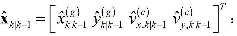
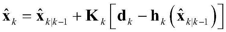
Obtaining estimated state of glider by the following formula
Wherein,
in order to estimate the position of the glider,
the estimated ocean current velocity direction component is obtained; f
k-1And L
k-1Respectively a state transition matrix and a control mapping matrix; v. of
k-1Two-dimensional plane velocity of relative water flow at time k-1 α
k-1Is an orientation angle; x is the number of
k-1Is the glider state at time k-1;
the model arrival time period difference Δ t is calculated by the following formulak′:
Wherein,
is the depth of the glider at time k, r, measured by its own sensor
kA distance vector representing the pointing of the beacon location from the estimated position of the glider with depth; | · | is a modulo operation; c is the speed of sound propagation in water;
calculating the model signal arrival angle theta by the following formulak′:
Wherein, gkIs the attitude vector of the glider at time k, phikIs the pitch angle of the glider;
establishing a measurement model hkThe following were used:
according to the measurement model h
kEstimating the underwater position of the glider by adopting an extended Kalman filter to obtain the state of the glider
And updating the error covariance matrix P
k;
(2.2) the estimation step of the position of the glider when the positioning signal is temporarily absent is as follows:
position of glider
Obtained by the following formula:
wherein,
for the most recent valid estimation of the water flow velocity,
the k and k-1 times differ by T seconds for the last estimated glider position.
Further, the error covariance matrix P
kIn (1), the element related to ocean current is set to 0.1
2The position-related elements are set as
Wherein v is
(l)The average speed of the glider is 0.5 knots.
Further, the glider state x at time k-1 in said step (2.1)
k-1The initial state of the glider is the initial position of the glider in the first underwater positioning, and the initial position and the ocean current speed of the glider in the step (2)
And (4) initial value composition.
Further, the underwater position of the glider is estimated by adopting an extended Kalman filter to obtain the state of the glider
And updating the error covariance matrix P
kThe method specifically comprises the following steps:
Pk|k-1=Fk-1Pk-1Fk-1 T+Qk-1
Pk=[I-KkHk]Pk|k-1
wherein, P
k|k-1The estimated error covariance matrix is obtained; q
k-1Is process noise; k
kIs the Kalman gain;
for the final estimated position of the glider,
is the final estimated ocean current velocity direction component; h
kIs h
kA jacobian matrix of; r
kTo observe the noise matrix.
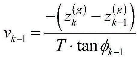
Further, the two-dimensional plane velocity v of the relative water flow at the time k-1k-1Calculated by the following formula:
wherein,
is a glider atDepth at time k, phi
k-1The pitch angle at time k-1.
Further, the speed of the ocean current in the step (2)
The initial value is set according to the priori knowledge of the ocean current, otherwise, the initial value is set to [ 00 ]]。
The invention has the beneficial effects that:
(1) the invention provides a positioning algorithm for an underwater glider under the influence of ocean currents, the position of the glider is estimated by combining the arrival time cycle difference and the arrival angle of a signal with extended Kalman filtering, and the positioning performance of the underwater glider can be greatly improved;
(2) the method estimates the position and the ocean current, compensates the position of the glider through the estimated ocean current, and improves the positioning performance of the glider under the influence of the ocean current;
(3) the algorithm of the invention does not need the glider to send signals, and does not need time synchronization between the beacon and the glider, and has the advantages of low power consumption and simple implementation;
(4) the beacon can be carried on any water surface or underwater platform, such as a water surface ship, a drilling platform, a buoy, a wave glider, a UUV, a submarine and the like;
(5) the sending period of the beacon positioning signal is variable;
(6) the method is used for processing the condition of the glider when the acoustic positioning signal is temporarily absent, so that the glider still has certain self-positioning performance under the condition of no effective acoustic positioning signal;
(7) the beacon can transmit data with the underwater glider in a single direction, and has certain communication capacity.
Drawings
One or more embodiments are illustrated by way of example in the accompanying drawings, which correspond to the figures in which like reference numerals refer to similar elements and which are not to scale unless otherwise specified.
Fig. 1 is a flowchart of a passive acoustic positioning method for an underwater glider without time synchronization according to an embodiment of the present invention;
fig. 2 is a beacon operation flow diagram provided by an embodiment of the present invention;
FIG. 3 is a diagram of simulation results provided by an embodiment of the present invention; wherein, (a) is a simulated scene graph; (b) a graph of the corresponding positioning error over time; (c) an ocean current estimation result graph is obtained;
FIG. 4 is a flow chart of data processing for calculating signal angle of arrival and signal inter-arrival time difference according to an embodiment of the present invention;
fig. 5 is a diagram of a positioning signal frame structure according to an embodiment of the present invention.
Detailed Description
The following detailed description of the present invention is provided in conjunction with the accompanying drawings, but it should be understood that the scope of the present invention is not limited to the specific embodiments.
In order to make the objects, technical solutions and advantages of the embodiments of the present invention clearer, the technical solutions in the embodiments of the present invention will be clearly and completely described below with reference to the drawings in the embodiments of the present invention, and it is obvious that the described embodiments are some, but not all, embodiments of the present invention. All other embodiments, which can be derived by a person skilled in the art from the embodiments given herein without making any creative effort, shall fall within the protection scope of the present invention. Throughout the specification and claims, unless explicitly stated otherwise, the word "comprise", or variations such as "comprises" or "comprising", will be understood to imply the inclusion of a stated element or component but not the exclusion of any other element or component.
The word "exemplary" is used exclusively herein to mean "serving as an example, embodiment, or illustration. Any embodiment described herein as "exemplary" is not necessarily to be construed as preferred or advantageous over other embodiments.
Furthermore, in the following detailed description, numerous specific details are set forth in order to provide a better understanding of the present invention. It will be understood by those skilled in the art that the present invention may be practiced without some of these specific details. In some instances, methods, means, elements well known to those skilled in the art have not been described in detail so as not to obscure the present invention.
Example 1
The embodiment of the invention provides a passive acoustic positioning method flow of an underwater glider under the influence of ocean currents, and the passive acoustic positioning method flow is shown in figure 1. The glider positions itself based on the difference in the arrival time periods of the received positioning signals and the angle of arrival (DOA) of the signals. The method comprises the following steps.
Step S1: deployment of glider, initialization of parameters
After the glider is deployed, the position of the glider is corrected by the GPS on the sea surface. And after the glider starts to sail underwater, continuously monitoring the signals and judging whether the positioning signals are received. Upon initialization, the ocean current velocity may be determined without prior knowledge of the ocean current
Initial value is set to [ 00%]If the priori knowledge is available, the speed of the ocean current can be determined
The initial values are set to corresponding values. Error covariance matrix P at initialization
kWherein the position-related element is based on a signaling interval
And typical velocity v of glider
(l)Is arranged as
The ocean current related element is set to 0.1
2。
Step S2: glider received signal processing step
A glider received signal processing step for analyzing and extracting the signal when the glider receives the signalTaking out signal arrival times
Angle of arrival theta of signal
kBeacon transmission time
And beacon location
The specific process, as shown in fig. 4, includes the following steps:
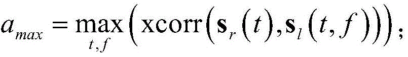
a. the received signals of the hydrophones are correlated and filtered with a Cyclic Algorithm (CAN) signal having good autocorrelation pre-stored in the glider. Recording the received signal sequence as s
r(t) the signal sequence of the local signal at the Doppler shift f is s
l(t, f), then in a given Doppler search space f ∈ [ f [ [ f ]
low,f
high]And the temporal search space T e [0, T ∈
s]Maximum value of whole search space obtained by searching
b. Finding the maximum output a that meets the signal detection threshold
maxThe time of occurrence is taken as the arrival time of the k-time signal
c. Then, the hydrophone array is subjected to beam forming to estimate the arrival angle of the signal
Wherein v is
H(φ) is the array response vector, φ is the orientation angle of the array response.
d. Decoding the signal to obtain information about the beacon transmission time
And beacon location
The data of (1).
Step S3-1: estimation step of glider position when positioning signal is effective
Firstly, estimating the two-dimensional plane speed of the current glider relative to water flow by using a sensor of the glider, estimating the speed by using the change of the depth and the value of the pitch angle in a period of time T, and recording the depth of the glider measured at the moment k by using the sensor of the glider as
The pitch angle at the time k-1 is phi
k-1And if the difference between the k time and the k-1 time is T seconds, the calculation method of the two-dimensional plane speed of the k-1 time relative to the water flow is as follows:
after obtaining the relative water flow velocity, the embodiment passes the signal arrival time measured in step S2
And a known signaling interval
Calculating the time period difference of arrival Δ t
k:
Will be Δ tkAnd angle of arrival thetakForming a column vector form to obtain a measurement vector d at the momentkSpecifically, the following are shown:
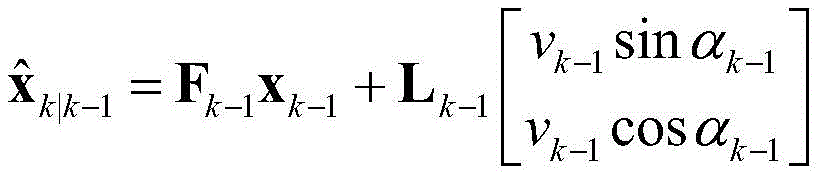
the state transition model of the glider is as follows:
wherein v is
k-1The two-dimensional plane velocity of the relative water flow at the moment k-1;
in order to be in a state of a glider,
in order to be the position of the glider,
is the speed of ocean current
A directional component of (a); f
k-1And L
k-1α for a state transition matrix and a control mapping matrix, respectively
k-1Is an orientation angle; q
k-1Is process noise;
the model arrival time period difference Δ t is calculated by the following formulak′:
Wherein,
is an estimated position of the glider, r
kA distance vector representing the direction of a beacon from a glider estimated position with depth; | · | is a modulo operation; c is the speed of sound propagation in water;
calculating the model signal arrival angle theta by the following formulak′:
Wherein, gkIs the attitude vector of the glider at time k,φkis the pitch angle of the glider;
establishing a measurement model hkThe following were used:
combining the estimated state transition model with the measurement model, the final state of the glider
And (3) updating the state through extended Kalman filtering:
a. predicting the estimated position of glider and the estimated ocean current by the following formula
b. The predicted covariance P is then corrected byk|k-1And (3) calculating:
Pk|k-1=Fk-1Pk-1Fk-1 T+Qk-1(10)
c. the kalman gain was calculated by the following formula:
wherein HkIs hkIn which R iskTo observe the noise matrix;
d. the error covariance matrix is calculated by the following equation in preparation for the next position estimate:
Pk=[I-KkHk]Pk|k-1(13)
e. the final estimated value of the position of the glider and the ocean current speed is obtained by the following two formulas
Wherein,
for the final estimated position of the glider,
is the direction component of the final estimated ocean current velocity.
Step S3-2: estimating the position of the glider when the acoustic positioning signal is temporarily absent:
in step 2-2 of this embodiment, the estimation step of the position of the glider when the acoustic positioning signal is temporarily absent or invalid enters the step if the signal sending time is not reached, the signal-to-noise ratio of the received signal is too low, the signal cannot be restored after the signal passes through the channel, and the like. First, the speed v of the glider relative to the water flow is calculated
k-1Reuse of the last estimated ocean current velocity
The current position is estimated by equation (1).
Wherein,
the k and k-1 times differ by T seconds for the last estimated glider position.
Fig. 3 shows a simulated scenario (fig. 3a), corresponding positioning error variation with time (fig. 3b), and ocean current estimation (fig. 3c) results according to an embodiment of the present invention. In the simulation, the beacon sails to the north and the east on the water surface, the ocean current is 40 degrees to the west of the north, and the glider sails to the south, but the actual direction is 77 degrees to the west of the north after being influenced by the ocean current. The error of the traditional dead reckoning method increases along with the increase of time, but through the process of the embodiment of the invention, the positioning accuracy of the glider at the final moment is improved by 94% compared with the traditional dead reckoning method, the average positioning error is not more than 100 meters, the positioning performance is greatly improved, and simultaneously at the final moment, the ocean currents in different directions estimated by the method are consistent with the actual situation.
Example 2
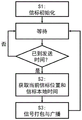
An embodiment of the present invention provides a procedure for sending a beacon positioning signal, as shown in fig. 2. In the embodiment, the beacon periodically broadcasts the positioning signal, and the beacon can be carried on any water surface or underwater platform, such as a water surface ship, a drilling platform, a buoy, a wave glider, a UUV, a submarine and the like. The method comprises the following steps:
step S1: beacon initialization procedure
The beacon sets the sending period of the positioning signal after deployment
Signal bandwidth and the like, and entering a waiting-to-send stage.
Step S2: step for obtaining current beacon position and beacon sending time
At the signal sending time, the beacon acquires the current position of the beacon
And beacon transmission time
Step S3: signal packing and broadcasting
The beacon position and beacon time obtained in step S2 of the CAN signal having a good autocorrelation are packaged and broadcast by the transducer, and the beacon enters the waiting state again after the broadcast is completed.
Example 3
Fig. 5 shows a frame structure of a positioning signal according to an embodiment of the present invention. The signal frame is composed of CAN signal with good autocorrelation and beacon position when transmitting
And transmission time
And (4) forming.
The product can execute the method provided by the embodiment of the invention, and has corresponding functional modules and beneficial effects of the execution method. For technical details that are not described in detail in this embodiment, reference may be made to the method provided by the embodiment of the present invention.
Finally, it should be noted that: the above examples are only intended to illustrate the technical solution of the present invention, but not to limit it; although the present invention has been described in detail with reference to the foregoing embodiments, it will be understood by those of ordinary skill in the art that: the technical solutions described in the foregoing embodiments may still be modified, or some technical features may be equivalently replaced; and such modifications or substitutions do not depart from the spirit and scope of the corresponding technical solutions of the embodiments of the present invention.