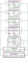
Disclosure of Invention
The invention aims to solve the problem of providing a method for carrying out integrated test on an intelligent driving vehicle, so that different simulation technologies based on the same test scene are shared in the project development process of a single ECU of the intelligent vehicle, thereby well verifying the function and performance of a controller and ensuring the safety and reliability of the vehicle in the actual driving process. Meanwhile, the same data are used in different ECU simulation tests of the intelligent vehicle, so that the cost is reduced, the coordination among different ECUs of the intelligent vehicle is good, and the test evaluation accuracy of the intelligent vehicle is improved.
The invention relates to a method for carrying out integrated test on an intelligent driving vehicle, which comprises the following specific steps:
①, realizing in-loop simulation test of the model under the virtual test scene aiming at the control strategy and algorithm of the intelligent vehicle;
②, realizing the software in-loop simulation test under the virtual test scene aiming at the code generated by the model or handwritten;
③, downloading the model code to the target hardware to realize the hardware-in-loop simulation test under the virtual test scene;
④, mounting the controller on the intelligent vehicle to realize the vehicle in-loop simulation test under the virtual test scene;
⑤, mounting the controller on an intelligent vehicle to realize real vehicle test in a real scene;
the test scenarios in the steps ① - ④ are the same virtual test scenario multiplexed;
each test method receives a test case defined by a test system as signal input, collects relevant evaluation index parameters, and compares the evaluation index parameters with the function definition index parameters to evaluate the control effect of the strategy/algorithm.
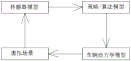
Further, the step of the model in-loop simulation test is as follows: under the virtual environment scene, the sensor model transmits scene data to the control strategy and the algorithm model, and the control strategy and the algorithm model calculate and control output based on the controlled vehicle dynamics model, so that the virtual vehicle acts under the virtual environment scene.
Furthermore, the model in-loop simulation test is based on an MAT L AB/Simulink design model and is assisted by a virtual environment scene, on the integration level, the technology is mainly used for quickly and simply debugging and optimizing the algorithm based on an MAT L AB software environment, and the intelligent vehicle strategy and algorithm and model level integration test are mainly verified in the stage.
Further, the software in-loop simulation test comprises the following steps: in the same virtual environment scene as the model in the loop simulation test, the sensor model transmits scene data to the model code, and the model code transmits processed data to the vehicle dynamics model, so that the virtual vehicle acts in the virtual environment scene.
Furthermore, the main purpose of the software in-loop simulation test is to verify whether the code generated based on the model or the handwritten code is consistent with the function of the model in step ①, the stage can reuse the virtual environment scenario used in step ①, early confirmation of the generated or handwritten code can be realized, and if a code problem is found in the test process, the problem of which model is specified can be quickly defined.
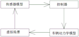
Further, the hardware-in-loop simulation test comprises the following steps: under the same virtual environment scene as the virtual environment scene of the model in the ring simulation test, the sensor model transmits scene data to the controller, and the controller calculates and processes the sensor data and transmits the processed data to the vehicle dynamics model, so that the virtual vehicle acts under the virtual environment scene.
Furthermore, the hardware-in-loop simulation test is to simulate the running state of the controlled object by running a simulation model through the controller, connect the controller with the tested ECU through the I/O interface, and perform comprehensive and systematic test on the tested ECU, and the stage can reuse the virtual environment scene used in the step ①.
Further, the vehicle in-loop simulation test comprises the following steps: a real-running intelligent vehicle detects a front virtual target (vehicle or pedestrian) through a corresponding virtual sensor in a virtual simulation environment of simulation software; and sending the detected obstacle information through a CAN message, receiving and transmitting the detected obstacle information to an ECU of the real vehicle by a sensor of the real vehicle, and further evaluating the external environment condition by the ECU so as to determine a corresponding control strategy.
Further, the vehicle in-loop simulation test is a novel simulation test technology which is applied to an intelligent vehicle for complex function test and verification work and aims to reduce test workload in the same time, has the advantages of virtual driving, integrates the advantages of the simulation technology in a mode of integrating real vehicles in a virtual traffic environment, considers real vehicle dynamic response and allows the function of personal experience, can be used for evaluation of interaction behaviors of a driver and a system, and can reuse a virtual environment scene used in the step ①.
Further, real vehicle testing in the real scene is carried out in a scene defined by functions; installing the developed system in a test vehicle and setting the actuating components (brake, steering wheel and engine control) in a closed loop; in most cases, the tests performed serve as a basis for further modifications of the system; the data recorded at this stage may be used as input for the simulation in all submitted scenarios.
Briefly, at the start of test validation, model-on-loop simulation tests will be used to validate smart car ECU control strategies and algorithms and model-level integration tests. Thereafter, automatically generated or manual ECU code from the model will be used by the software in the loop simulation test. This step brings greater confidence in the implementation of the software without requiring ECU hardware. At this level, the functional test scenario of model-in-loop simulation testing may be multiplexed to verify other functions of the ECU. Finally, the software is downloaded to the target hardware and hardware-in-the-loop techniques are used to verify that the software behavior is the same as that observed in the model-in-the-loop and software-in-the-loop tests. The vehicle in-loop simulation test overcomes the limitation of the known traditional real vehicle road test, namely, the vehicle in-loop simulation test is realized by integrating a virtual simulation technology and a conventional road test method. The method takes into account real vehicle dynamics effects and allows for an in-person experience functionality for assessment of driver interaction behavior with the system. Real-vehicle closed-loop testing is final verification at an integration level, and is used as a basis for further modification of the system, and test data is collected and used as simulation input.
On each level of simulation, the operating environment of the ECU may be virtually or simulatively reconstructed (that is, test scenario data generated by driver, vehicle, traffic conditions, and environmental interactions are recorded during the test and then reproduced in the virtual environment). The simulation may be open loop (without ambient feedback) or closed loop (with ambient feedback). Real-vehicle closed-loop testing may be considered final verification at the level of integration.
The invention has the advantages that: 1. virtual scene data are multiplexed on models, software, hardware of the ECU and each simulation level of the vehicle in the ring simulation test, and real-time simulation is also included, so that the comparability of test results is ensured, the calculation model is verified, and if a problem exists, the calculation model can be modified in time. Meanwhile, the function and the performance of the controller are well verified, and the safety and the reliability of the vehicle in the actual driving process are ensured. 2. Virtual or simulation reconstructed data are multiplexed in different ECU simulation tests of the intelligent vehicle, so that the cost is reduced, the coordination among different ECUs is ensured, and the test evaluation accuracy of the intelligent vehicle is improved. 3. When performing simulation on a multi-core computing cluster, simulation time may be reduced.
In a word, the invention reduces the times of actual vehicle road tests, shortens the development time, reduces the cost, improves the software quality of the ECU and reduces the risk of intelligent vehicle developers.
Detailed Description
In order to make the technical solutions of the present invention better understood, the present invention will be described in further detail with reference to the accompanying drawings and specific embodiments.
The invention relates to a method for carrying out integrated test on an intelligent driving vehicle, which comprises the following specific steps:
①, realizing the model in-loop simulation test under the virtual test scene aiming at the intelligent vehicle control strategy or algorithm;
②, realizing the software in-loop simulation test under the virtual test scene aiming at the code generated by the model or handwritten;
③, downloading the model code to the target hardware to realize the hardware-in-loop simulation test under the virtual test scene;
④, mounting the controller on the intelligent vehicle to realize the vehicle in-loop simulation test under the virtual test scene;
⑤, mounting the controller on an intelligent vehicle to realize real vehicle test in a real scene;
the test scenarios in the steps ① - ④ are the same virtual test scenario multiplexed;
each test method receives a test case defined by a test system as signal input, collects relevant evaluation index parameters, and compares the evaluation index parameters with the function definition index parameters to evaluate the control effect of the strategy/algorithm.
Before the integrated test is carried out, a test scene needs to be constructed, wherein the test scene can be a virtual test scene reconstructed based on the acquired real driving data, and can also be a virtual test scene constructed through virtual software based on test standards, test personnel experience or extreme test requirements. It can thus be seen that the test method of the present invention relies most on data. To ensure the accuracy of the test results, a large amount of data is required.
The specific steps of data acquisition and verification used in the test scenario are as follows:
(1) data acquisition
The data source has two parts: real driving data collected based on vehicle-mounted sensors during human driving or automatic driving, wherein the data not only comprise information of position and speed, but also comprise classification (automobiles, pedestrians and the like), type (oncoming, disappearing, still, moving and the like), confidence level of the data and the like of the information; second, the raw data may also be generated virtually based on simulation software. For example, MotionDesk by Dspace/ASM Traffic is one of the commercial software tools that support virtual road scene generation. The software allows a user to define virtual reality, including targets that can be defined in a virtual reality environment: vehicles, buildings, roads, weather and various obstacles, and their behaviors.
(2) Data storage
The collected data requires a large amount of storage resources. Since individual files are large, it is very inconvenient to copy them and operate on a PC. Therefore, a large amount of data needs to be processed by the computing cluster device, and almost all data operations can be completed on the cluster for ethernet communication.
(3) Data processing and verification
Data collected during driving tests requires validation. This is typically done manually by looking at the log and choosing the cases that the algorithm gives different results than expected. However, manual completion is very time consuming and a method can be devised to automatically accomplish these screenings. This not only saves time for analysis, but can also classify logs into specific categories. Such as: high speed working conditions, urban working conditions, pedestrians or people riding bicycles, and the like, and classified and registered. Thus, in the future, logs may be quickly selected from the categories of interest, and then all changes quickly verified.
Step 1. model in-loop simulation test
The main purpose of the Model-in-the-loop-MI L simulation test is to verify the function implementation of the intelligent vehicle strategy and algorithm Model and the determination of the Model level.
The testing steps are as follows: under the virtual environment scene, the sensor model transmits scene data to the control strategy and the algorithm model, and the control strategy and the algorithm model calculate and control output based on the controlled vehicle dynamics model, so that the virtual vehicle acts under the virtual environment scene.
The model tests MAT L AB/Simulink based control strategy and algorithm models in a ring simulation, supplemented with virtual environment scenarios at this integration level, the technology allows for fast and simple debugging and optimization of control strategies and algorithms using a well-known MAT L AB software environment.
Step 2: software in-the-loop simulation test
The main purpose of the software-in-the-loop-MI L simulation test is to verify whether the Model code generated based on the Model is consistent with the Model function used for code generation.
The testing steps are as follows: in the same virtual environment scene as the model in the loop simulation test, the sensor model transmits scene data to the model code, and the model code transmits processed data to the vehicle dynamics model, so that the virtual vehicle acts in the virtual environment scene. The code in this step is either generated based on the control strategy and algorithm model in step 1 or handwritten code.
This stage reuses the virtual environment scenario used in step 1 and can enable early validation of generated code or handwritten code. If a code problem is found in the test process, the problem of which model is specified can be quickly defined, so that relevant processing is carried out.
Step 3, hardware-in-loop simulation test
The main purpose of Hardware-in-the-loop-HI L simulation test is to verify the Hardware adaptability and real-time effect of control strategies and algorithms.
The testing steps are as follows: under the same virtual environment scene as the virtual environment scene of the model in the ring simulation test, the sensor model transmits scene data to the controller, and the controller calculates and processes the sensor data and transmits the processed data to the vehicle dynamics model, so that the virtual vehicle acts under the virtual environment scene. The model code in step 2 is compiled and downloaded into the target controller hardware.
In the stage, a controller operates a simulation model to simulate the operating state of a controlled object, and the controlled object is connected with the tested ECU through an I/O interface to carry out all-around and systematic testing on the tested ECU.
This stage reuses the virtual environment scenario used in step 1, and in addition to reducing cost, another advantage is the ability to create specific scenarios that the tester wants to test the model. In consideration of safety, feasibility and cost, hardware-in-loop simulation test becomes a very important loop in the ECU development process, the times of real vehicle road tests are reduced, the development time is shortened, the cost is reduced, the software quality of the ECU is improved, and the risk of intelligent vehicle developers is reduced.
The HI L test system can simulate drivers, vehicles and working environments thereof, and is an ideal laboratory tool for automatically testing Electronic Control Systems (ECUs). The test method has the advantages of separating the test process from a test bench, testing the ECUs under limit or dangerous conditions without causing harm to testers or vehicles, conveniently simulating various working conditions of a controlled object and various state combination relations among input signals, quickly simulating/reproducing complex fault modes, identifying the root causes of complex faults in the early stage of ECU development, realizing multi-ECU integrated test, realizing all-weather automatic test, wider automatic test coverage range than manual test coverage, being easy to maintain and expand test capability, shortening the development period and saving the development cost.
The following describes the hardware-in-the-loop simulation test in detail, taking a specific lane keeping control system (L KA) as an example:
the method comprises the steps of establishing a virtual test scene, transmitting an image to a display through a VGA, obtaining the image of the scene by using a real camera and transmitting the image to a L KA controller, calculating and processing image information by the controller, outputting instructions such as steering wheel angles and vehicle speeds, and outputting the instructions to a vehicle dynamic model through a CAN bus, so that a virtual vehicle performs related actions in the virtual scene through a driver model.
Step 4, vehicle in-loop simulation test
The purpose of the Vehicle simulation test in the loop (Vehicle-in-the-loop-VI L) is to verify the functional implementation under the real dynamic characteristics.
The vehicle in-loop simulation test is a novel simulation test technology which is applied to an intelligent vehicle to reduce the test workload in the same time when complex function test and verification work are carried out. The method not only has the advantage of virtual driving, but also integrates the advantages of simulation technology in a mode of integrating real vehicles in a virtual traffic environment.
The VI L technique overcomes the limitations of known conventional real vehicle road tests by integrating virtual simulation techniques with conventional road tests, to this end, a real vehicle will be "embedded" into a virtual traffic environment (including traffic scenes, traffic signs, roads, etc.) and can be tested in an open outdoor venue.
A real-running intelligent vehicle detects a front virtual target (vehicle or pedestrian) through a corresponding virtual sensor in a virtual simulation environment of simulation software; and sending the detected obstacle information through a CAN message, receiving and transmitting the detected obstacle information to an ECU of the real vehicle by a sensor of the real vehicle, and further evaluating the external environment condition by the ECU so as to determine a corresponding control strategy. The vehicle in this step has installed the controller in step 3. Scene information in the simulation scene is transmitted to the controller through the sensor model, meanwhile, the virtual test scene is transmitted to the display, the real camera is used for obtaining an image of the scene and transmitting the target information to the controller, the controller sends out instructions of acceleration, braking, steering and the like, and the intelligent vehicle performs corresponding actions according to the instructions. The driver may choose different scenarios to do this test repeatedly.
This technique has the following advantages: true vehicle dynamics response, allowing for in-person experience functionality; less equipment and hardware investment; can be used for evaluating the interaction behavior of the driver and the system.
Each step of simulation test receives a test case defined by a test system as signal input, collects relevant evaluation index parameters, and compares the evaluation index parameters with the function definition index parameters to evaluate the control effect of the strategy/algorithm.
And 5: real vehicle closed loop test
As the last step of development and test of the intelligent vehicle control strategy and algorithm, the integration test in a real scene is carried out in a scene defined by functions. The developed system was installed in a test vehicle and the actuating components (brake, steering wheel and engine control) were placed in a closed loop. The demonstration scenario requires the test vehicle to perform operations such as adjusting speed, autobraking, etc. As a verification method for positioning, accurate real-time recording of absolute coordinates, speed and acceleration data of a self-vehicle and a target object reference positioning system is required. Data obtained from the positioning system is used for benchmarking and performance verification of post-test processing. Demonstration function test cases are typically set according to NCAP or NHTSA. In most cases, the tests performed are taken as a basis for further modifications of the system. The data recorded at this stage may be used as input for the simulation in all submitted scenarios. This step may be performed after all ECUs have completed the above 4 simulation tests and then collectively mounted on the test vehicle, or may be performed individually by each ECU.
The following describes the real-vehicle closed-loop test in detail, taking the lane keeping control system (L KA) as an example:
the test vehicle automatic driving sample vehicle platform based on the Drive PX2 comprises 1) an L KA system function, 2) two Driver PX2 calculation platforms, one Driver PX2 calculation platform is used for environment perception calculation processing and the other Driver PX2 calculation platform is used for motion control calculation processing, an NVIDIA camera is used for acquiring lane information, 3) a positioning system is used for realizing differential positioning by GPS receiving and transmitting equipment, a NoVtel fixed base station and a SPAN-CPT, and 4) a data acquisition system is used for carrying out data transmission by a notebook computer operation data acquisition and analysis program and a CANalst-II.
The test process comprises the steps of 1, base line collection, 2, enabling a sample vehicle to be in an L KA system working state, 3, operating a data collection system, collecting information such as a sample vehicle driving coordinate, a vehicle speed and a corner, 4, obtaining a driving track through data off-line processing, 5, comparing the driving track of the sample vehicle L KA with the base line track, and evaluating the L KA function and performance of the sample vehicle.
In the real-vehicle closed-loop test, the camera simultaneously records a driving scene in the test process, and the scene can be used as a source of the reconstructed scene in the steps ① - ④ to expand the reconstructed virtual scene.