CN110780364A - Light control film and display device including the light control film - Google Patents

Light control film and display device including the light control film Download PDF

Info

Publication number
CN110780364A
CN110780364A CN201910689814.3A CN201910689814A CN110780364A CN 110780364 A CN110780364 A CN 110780364A CN 201910689814 A CN201910689814 A CN 201910689814A CN 110780364 A CN110780364 A CN 110780364A
Authority
CN
China
Prior art keywords
layer
light
light control
lens
control film
Prior art date
Legal status (The legal status is an assumption and is not a legal conclusion. Google has not performed a legal analysis and makes no representation as to the accuracy of the status listed.)
Granted
Application number
CN201910689814.3A
Other languages
Chinese (zh)
Other versions
CN110780364B (en
Inventor
李世民
金在辰
韩载政
金镇炼
金大用
尹龙重
Current Assignee (The listed assignees may be inaccurate. Google has not performed a legal analysis and makes no representation or warranty as to the accuracy of the list.)
LG Display Co Ltd
Original Assignee
LG Display Co Ltd
Priority date (The priority date is an assumption and is not a legal conclusion. Google has not performed a legal analysis and makes no representation as to the accuracy of the date listed.)
Filing date
Publication date
Priority claimed from KR1020180170611A external-priority patent/KR102652568B1/en
Application filed by LG Display Co Ltd filed Critical LG Display Co Ltd
Publication of CN110780364A publication Critical patent/CN110780364A/en
Application granted granted Critical
Publication of CN110780364B publication Critical patent/CN110780364B/en
Active legal-status Critical Current
Anticipated expiration legal-status Critical

Links

Images

Classifications

    • GPHYSICS
    • G06COMPUTING OR CALCULATING; COUNTING
    • G06FELECTRIC DIGITAL DATA PROCESSING
    • G06F3/00Input arrangements for transferring data to be processed into a form capable of being handled by the computer; Output arrangements for transferring data from processing unit to output unit, e.g. interface arrangements
    • G06F3/01Input arrangements or combined input and output arrangements for interaction between user and computer
    • G06F3/03Arrangements for converting the position or the displacement of a member into a coded form
    • G06F3/041Digitisers, e.g. for touch screens or touch pads, characterised by the transducing means
    • G06F3/0412Digitisers structurally integrated in a display
    • GPHYSICS
    • G02OPTICS
    • G02BOPTICAL ELEMENTS, SYSTEMS OR APPARATUS
    • G02B3/00Simple or compound lenses
    • G02B3/0006Arrays
    • G02B3/0037Arrays characterized by the distribution or form of lenses
    • G02B3/0056Arrays characterized by the distribution or form of lenses arranged along two different directions in a plane, e.g. honeycomb arrangement of lenses
    • GPHYSICS
    • G02OPTICS
    • G02BOPTICAL ELEMENTS, SYSTEMS OR APPARATUS
    • G02B5/00Optical elements other than lenses
    • G02B5/003Light absorbing elements
    • GPHYSICS
    • G02OPTICS
    • G02BOPTICAL ELEMENTS, SYSTEMS OR APPARATUS
    • G02B5/00Optical elements other than lenses
    • G02B5/02Diffusing elements; Afocal elements
    • G02B5/0205Diffusing elements; Afocal elements characterised by the diffusing properties
    • G02B5/021Diffusing elements; Afocal elements characterised by the diffusing properties the diffusion taking place at the element's surface, e.g. by means of surface roughening or microprismatic structures
    • G02B5/0215Diffusing elements; Afocal elements characterised by the diffusing properties the diffusion taking place at the element's surface, e.g. by means of surface roughening or microprismatic structures the surface having a regular structure
    • GPHYSICS
    • G02OPTICS
    • G02BOPTICAL ELEMENTS, SYSTEMS OR APPARATUS
    • G02B5/00Optical elements other than lenses
    • G02B5/02Diffusing elements; Afocal elements
    • G02B5/0273Diffusing elements; Afocal elements characterized by the use
    • G02B5/0278Diffusing elements; Afocal elements characterized by the use used in transmission
    • GPHYSICS
    • G02OPTICS
    • G02FOPTICAL DEVICES OR ARRANGEMENTS FOR THE CONTROL OF LIGHT BY MODIFICATION OF THE OPTICAL PROPERTIES OF THE MEDIA OF THE ELEMENTS INVOLVED THEREIN; NON-LINEAR OPTICS; FREQUENCY-CHANGING OF LIGHT; OPTICAL LOGIC ELEMENTS; OPTICAL ANALOGUE/DIGITAL CONVERTERS
    • G02F1/00Devices or arrangements for the control of the intensity, colour, phase, polarisation or direction of light arriving from an independent light source, e.g. switching, gating or modulating; Non-linear optics
    • G02F1/01Devices or arrangements for the control of the intensity, colour, phase, polarisation or direction of light arriving from an independent light source, e.g. switching, gating or modulating; Non-linear optics for the control of the intensity, phase, polarisation or colour 
    • G02F1/13Devices or arrangements for the control of the intensity, colour, phase, polarisation or direction of light arriving from an independent light source, e.g. switching, gating or modulating; Non-linear optics for the control of the intensity, phase, polarisation or colour  based on liquid crystals, e.g. single liquid crystal display cells
    • G02F1/133Constructional arrangements; Operation of liquid crystal cells; Circuit arrangements
    • G02F1/1333Constructional arrangements; Manufacturing methods
    • G02F1/1335Structural association of cells with optical devices, e.g. polarisers or reflectors
    • G02F1/1336Illuminating devices
    • G02F1/133602Direct backlight
    • G02F1/133603Direct backlight with LEDs
    • GPHYSICS
    • G02OPTICS
    • G02FOPTICAL DEVICES OR ARRANGEMENTS FOR THE CONTROL OF LIGHT BY MODIFICATION OF THE OPTICAL PROPERTIES OF THE MEDIA OF THE ELEMENTS INVOLVED THEREIN; NON-LINEAR OPTICS; FREQUENCY-CHANGING OF LIGHT; OPTICAL LOGIC ELEMENTS; OPTICAL ANALOGUE/DIGITAL CONVERTERS
    • G02F1/00Devices or arrangements for the control of the intensity, colour, phase, polarisation or direction of light arriving from an independent light source, e.g. switching, gating or modulating; Non-linear optics
    • G02F1/01Devices or arrangements for the control of the intensity, colour, phase, polarisation or direction of light arriving from an independent light source, e.g. switching, gating or modulating; Non-linear optics for the control of the intensity, phase, polarisation or colour 
    • G02F1/13Devices or arrangements for the control of the intensity, colour, phase, polarisation or direction of light arriving from an independent light source, e.g. switching, gating or modulating; Non-linear optics for the control of the intensity, phase, polarisation or colour  based on liquid crystals, e.g. single liquid crystal display cells
    • G02F1/133Constructional arrangements; Operation of liquid crystal cells; Circuit arrangements
    • G02F1/1333Constructional arrangements; Manufacturing methods
    • G02F1/1335Structural association of cells with optical devices, e.g. polarisers or reflectors
    • G02F1/1336Illuminating devices
    • G02F1/133602Direct backlight
    • G02F1/133606Direct backlight including a specially adapted diffusing, scattering or light controlling members
    • GPHYSICS
    • G02OPTICS
    • G02FOPTICAL DEVICES OR ARRANGEMENTS FOR THE CONTROL OF LIGHT BY MODIFICATION OF THE OPTICAL PROPERTIES OF THE MEDIA OF THE ELEMENTS INVOLVED THEREIN; NON-LINEAR OPTICS; FREQUENCY-CHANGING OF LIGHT; OPTICAL LOGIC ELEMENTS; OPTICAL ANALOGUE/DIGITAL CONVERTERS
    • G02F1/00Devices or arrangements for the control of the intensity, colour, phase, polarisation or direction of light arriving from an independent light source, e.g. switching, gating or modulating; Non-linear optics
    • G02F1/01Devices or arrangements for the control of the intensity, colour, phase, polarisation or direction of light arriving from an independent light source, e.g. switching, gating or modulating; Non-linear optics for the control of the intensity, phase, polarisation or colour 
    • G02F1/13Devices or arrangements for the control of the intensity, colour, phase, polarisation or direction of light arriving from an independent light source, e.g. switching, gating or modulating; Non-linear optics for the control of the intensity, phase, polarisation or colour  based on liquid crystals, e.g. single liquid crystal display cells
    • G02F1/133Constructional arrangements; Operation of liquid crystal cells; Circuit arrangements
    • G02F1/1333Constructional arrangements; Manufacturing methods
    • G02F1/1337Surface-induced orientation of the liquid crystal molecules, e.g. by alignment layers
    • G02F1/133707Structures for producing distorted electric fields, e.g. bumps, protrusions, recesses, slits in pixel electrodes
    • GPHYSICS
    • G09EDUCATION; CRYPTOGRAPHY; DISPLAY; ADVERTISING; SEALS
    • G09FDISPLAYING; ADVERTISING; SIGNS; LABELS OR NAME-PLATES; SEALS
    • G09F9/00Indicating arrangements for variable information in which the information is built-up on a support by selection or combination of individual elements
    • GPHYSICS
    • G02OPTICS
    • G02BOPTICAL ELEMENTS, SYSTEMS OR APPARATUS
    • G02B2207/00Coding scheme for general features or characteristics of optical elements and systems of subclass G02B, but not including elements and systems which would be classified in G02B6/00 and subgroups
    • G02B2207/123Optical louvre elements, e.g. for directional light blocking
    • GPHYSICS
    • G02OPTICS
    • G02BOPTICAL ELEMENTS, SYSTEMS OR APPARATUS
    • G02B5/00Optical elements other than lenses
    • G02B5/30Polarising elements
    • G02B5/3025Polarisers, i.e. arrangements capable of producing a definite output polarisation state from an unpolarised input state
    • G02B5/3033Polarisers, i.e. arrangements capable of producing a definite output polarisation state from an unpolarised input state in the form of a thin sheet or foil, e.g. Polaroid
    • GPHYSICS
    • G02OPTICS
    • G02FOPTICAL DEVICES OR ARRANGEMENTS FOR THE CONTROL OF LIGHT BY MODIFICATION OF THE OPTICAL PROPERTIES OF THE MEDIA OF THE ELEMENTS INVOLVED THEREIN; NON-LINEAR OPTICS; FREQUENCY-CHANGING OF LIGHT; OPTICAL LOGIC ELEMENTS; OPTICAL ANALOGUE/DIGITAL CONVERTERS
    • G02F1/00Devices or arrangements for the control of the intensity, colour, phase, polarisation or direction of light arriving from an independent light source, e.g. switching, gating or modulating; Non-linear optics
    • G02F1/01Devices or arrangements for the control of the intensity, colour, phase, polarisation or direction of light arriving from an independent light source, e.g. switching, gating or modulating; Non-linear optics for the control of the intensity, phase, polarisation or colour 
    • G02F1/13Devices or arrangements for the control of the intensity, colour, phase, polarisation or direction of light arriving from an independent light source, e.g. switching, gating or modulating; Non-linear optics for the control of the intensity, phase, polarisation or colour  based on liquid crystals, e.g. single liquid crystal display cells
    • G02F1/133Constructional arrangements; Operation of liquid crystal cells; Circuit arrangements
    • G02F1/1333Constructional arrangements; Manufacturing methods
    • G02F1/1335Structural association of cells with optical devices, e.g. polarisers or reflectors
    • G02F1/1336Illuminating devices
    • G02F1/133602Direct backlight
    • G02F1/133606Direct backlight including a specially adapted diffusing, scattering or light controlling members
    • G02F1/133607Direct backlight including a specially adapted diffusing, scattering or light controlling members the light controlling member including light directing or refracting elements, e.g. prisms or lenses

Landscapes

  • Physics & Mathematics (AREA)
  • General Physics & Mathematics (AREA)
  • Optics & Photonics (AREA)
  • Nonlinear Science (AREA)
  • Engineering & Computer Science (AREA)
  • Chemical & Material Sciences (AREA)
  • Mathematical Physics (AREA)
  • Crystallography & Structural Chemistry (AREA)
  • Theoretical Computer Science (AREA)
  • General Engineering & Computer Science (AREA)
  • Spectroscopy & Molecular Physics (AREA)
  • Human Computer Interaction (AREA)
  • Optical Elements Other Than Lenses (AREA)
  • Electroluminescent Light Sources (AREA)

Abstract

本公开涉及光控膜和包括该光控膜的显示装置,所述光控膜包括第一基膜、在第一基膜的一个表面上的透镜部和在第一基膜的另一表面上的视角控制器。透镜部包括多个光学图案,并且视角控制器包括多个狭缝。

The present disclosure relates to a light control film including a first base film, a lens portion on one surface of the first base film, and a display device including the light control film, and a light control film on the other surface of the first base film view controller. The lens portion includes a plurality of optical patterns, and the viewing angle controller includes a plurality of slits.

Description

光控膜和包括该光控膜的显示装置Light control film and display device including the light control film

技术领域technical field

本公开内容涉及光控膜和包括该光控膜的显示装置。The present disclosure relates to light control films and display devices including the light control films.

背景技术Background technique

诸如液晶显示(LCD)装置和电致发光显示装置的显示装置易于实现高分辨率并且具有大屏幕显示装置的各种优点。Display devices such as liquid crystal display (LCD) devices and electroluminescence display devices are easy to achieve high resolution and have various advantages of large-screen display devices.

显示装置均包括用于显示图像的显示面板。显示面板包括多个像素,并且多个像素中的每个像素包括用于实现各个颜色的多个子像素。例如,多个像素中的每个像素可以包括红色子像素、绿色子像素和蓝色子像素。The display devices each include a display panel for displaying images. The display panel includes a plurality of pixels, and each pixel of the plurality of pixels includes a plurality of sub-pixels for realizing respective colors. For example, each of the plurality of pixels may include a red sub-pixel, a green sub-pixel, and a blue sub-pixel.

然而,现有技术的显示装置具有如下问题:从显示面板发出的基于光波长的光的量相对于侧视角出现差异,从而引起图像质量降低。例如,在电致发光显示装置中,单个子像素发出单独颜色的光,但是在从各个子像素发射的光被释放到显示面板的上表面的情况下,以光波长为单位发射的光的量相对于侧视角出现差异,从而引起图像质量降低。具体地,与诸如红光的长波长光相比,诸如蓝光的发射的短波长光的量相对于侧视角增加,导致显示完全偏蓝的图像的问题。However, the related art display device has a problem in that the amount of light based on the wavelength of light emitted from the display panel varies with respect to the side viewing angle, thereby causing a reduction in image quality. For example, in an electroluminescent display device, a single sub-pixel emits light of individual colors, but in the case where the light emitted from each sub-pixel is released to the upper surface of the display panel, the amount of light emitted in units of light wavelengths There is a difference relative to the side viewing angle, causing a reduction in image quality. Specifically, the amount of emitted short-wavelength light, such as blue light, increases relative to the side viewing angle, compared to long-wavelength light, such as red light, resulting in a problem of displaying a completely bluish image.

发明内容SUMMARY OF THE INVENTION

因此,本公开内容旨在提供基本上消除了由于现有技术的限制和缺点引起的一个或更多个问题的光控膜和包括该光控膜的显示装置。Accordingly, the present disclosure seeks to provide light control films and display devices including the same that substantially obviate one or more of the problems due to limitations and disadvantages of the related art.

本公开内容的一个方面涉及提供一种光控膜,其包括用于改善相对于第一方向上的侧视角的图像的透镜部和用于阻挡在垂直于第一方向的第二方向上的侧光的视角控制器,从而解决了相对于侧视角显示偏蓝的图像的问题。One aspect of the present disclosure relates to providing a light control film including a lens portion for improving an image with respect to a side viewing angle in a first direction and a side for blocking a side in a second direction perpendicular to the first direction The viewing angle controller of the light, thus solving the problem of displaying a bluish image relative to the side viewing angle.

本公开内容的另一方面涉及提供一种光控膜,其包括:透镜部,包括规则或不规则地布置的多个光学图案;以及视角控制器,包括沿第一方向延伸并在垂直于第一方向的第二方向上彼此间隔开的多个狭缝,从而改善相对于侧视角的图像、增强安全性并减少相位显示现象。Another aspect of the present disclosure is directed to providing a light control film including: a lens portion including a plurality of optical patterns arranged regularly or irregularly; and a viewing angle controller including extending along a first direction and perpendicular to a second direction A plurality of slits spaced apart from each other in the second direction of one direction, thereby improving the image relative to the side viewing angle, enhancing security and reducing the phase display phenomenon.

本公开内容的另一方面涉及提供一种光控膜,其包括用于在多个方向上改善相对于侧视角的图像的透镜部和用于阻挡在垂直于第一方向的第二方向上的侧光的视角控制器,从而在多个方向上改善相对于侧视角的图像并减少相位显示现象。Another aspect of the present disclosure relates to providing a light control film including a lens portion for improving an image in multiple directions relative to a side viewing angle and for blocking a light control film in a second direction perpendicular to the first direction Viewing angle controller for side lighting, which improves the image relative to the side viewing angle in multiple directions and reduces the phase display phenomenon.

本公开内容的其他优点和特征将部分地在下面的描述中阐述,并且部分地对于本领域普通技术人员在研究以下内容时将变得明显,或者可以从本公开内容的实践中获知。本公开内容的目的和其他优点可以通过在撰写的说明书及其权利要求书以及附图中特别指出的结构来实现和获得。Other advantages and features of the present disclosure will be set forth in part in the description that follows, and in part will become apparent to those of ordinary skill in the art upon study of the following, or may be learned from practice of the disclosure. The objectives and other advantages of the present disclosure may be realized and attained by the structure particularly pointed out in the written description and claims hereof as well as the appended drawings.

为了实现这些和其他优点并且根据本公开内容的目的,如本文所实施和广泛描述的,提供了一种光控膜,其包括:第一基膜;在第一基膜的一个表面上的透镜部,透镜部包括多个光学图案;以及在第一基膜的另一表面上的视角控制器,视角控制器包括多个狭缝。To achieve these and other advantages and in accordance with the purposes of the present disclosure, as embodied and broadly described herein, there is provided a light control film comprising: a first base film; a lens on one surface of the first base film the lens part includes a plurality of optical patterns; and a viewing angle controller on the other surface of the first base film, the viewing angle controller includes a plurality of slits.

在本公开内容的另一方面,提供一种光控膜,其包括:第一基膜;透镜部,其包括设置在第一基膜的一个表面上的第一透镜层和与第一透镜层交叠的第二透镜层,第一透镜层包括第一光学图案并且第二透镜层包括与第一光学图案不同的第二光学图案;以及在第一基膜的另一表面上的视角控制器,视角控制器包括多个狭缝。In another aspect of the present disclosure, there is provided a light control film including: a first base film; a lens portion including a first lens layer disposed on one surface of the first base film and a contact with the first lens layer overlapping second lens layers, the first lens layer including a first optical pattern and the second lens layer including a second optical pattern different from the first optical pattern; and a viewing angle controller on the other surface of the first base film , the viewing angle controller includes a plurality of slits.

在本公开内容的另一方面,提供了一种显示装置,其包括:显示面板;在显示面板上的偏振膜;在偏振膜上的触摸面板;以及光控膜,其包括第一基膜、在第一基膜的一个表面上的透镜部、以及在第一基膜的另一表面上的视角控制器,透镜部包括多个光学图案并且视角控制器包括多个狭缝。In another aspect of the present disclosure, there is provided a display device including: a display panel; a polarizing film on the display panel; a touch panel on the polarizing film; and a light control film including a first base film, A lens portion on one surface of the first base film, and a viewing angle controller on the other surface of the first base film, the lens portion includes a plurality of optical patterns and the viewing angle controller includes a plurality of slits.

其他实施方式的细节包括在具体实施方式和附图中。Details of other embodiments are included in the Detailed Description and the accompanying drawings.

应当理解,本公开内容的前述一般描述和以下详细描述都是示例性和说明性的,并且旨在提供对要求保护的本公开内容的进一步说明。It is to be understood that both the foregoing general description and the following detailed description of the present disclosure are exemplary and explanatory and are intended to provide further explanation of the present disclosure as claimed.

附图说明Description of drawings

附图被包括以提供对本公开内容的进一步理解,并且附图并入本申请中并且构成本申请的一部分,附图示出了本公开内容的实施方式,并且附图与说明书一起用于说明本公开内容的原理。在附图中:The accompanying drawings, which are included to provide a further understanding of the present disclosure, are incorporated in and constitute a part of this application, illustrate embodiments of the present disclosure, and together with the description serve to explain the present disclosure Principles of disclosure. In the attached image:

图1是示出根据本公开内容的第一实施方式的光控膜的截面图;1 is a cross-sectional view illustrating a light control film according to a first embodiment of the present disclosure;

图2是示出根据本公开内容的第二实施方式的光控膜的截面图;2 is a cross-sectional view illustrating a light control film according to a second embodiment of the present disclosure;

图3是示出根据本公开内容的第三实施方式的光控膜的截面图;3 is a cross-sectional view illustrating a light control film according to a third embodiment of the present disclosure;

图4是示出根据本公开内容的第四实施方式的光控膜的截面图;4 is a cross-sectional view illustrating a light control film according to a fourth embodiment of the present disclosure;

图5A和图5B是示出通过使用根据本公开内容的实施方式的透镜部以波长为单位调节的光路的示图;5A and 5B are diagrams illustrating optical paths adjusted in units of wavelengths by using a lens portion according to an embodiment of the present disclosure;

图6是示出根据本公开内容的另一实施方式的透镜部的截面图;6 is a cross-sectional view illustrating a lens portion according to another embodiment of the present disclosure;

图7是示出根据本公开内容的实施方式的透镜部的多个光学图案的平面图;7 is a plan view illustrating a plurality of optical patterns of a lens portion according to an embodiment of the present disclosure;

图8是示出根据本公开内容的另一实施方式的透镜部的多个光学图案的平面图;8 is a plan view illustrating a plurality of optical patterns of a lens portion according to another embodiment of the present disclosure;

图9是示出在显示面板上设置有根据本公开内容的实施方式的透镜部的多个光学图案的情况下的光路的图;9 is a diagram illustrating an optical path in a case where a plurality of optical patterns of a lens portion according to an embodiment of the present disclosure are provided on a display panel;

图10A是示出在显示面板上设置有根据本公开内容的实施方式的透镜部的示例的截面图;10A is a cross-sectional view illustrating an example in which a lens portion according to an embodiment of the present disclosure is provided on a display panel;

图10B是示出在显示面板上设置有根据本公开内容的实施方式的透镜部的情况下的光路的图;10B is a diagram illustrating an optical path in a case where a lens portion according to an embodiment of the present disclosure is provided on a display panel;

图11是示出在显示面板上设置有根据本公开内容的实施方式的光控膜的情况下的光路的图;11 is a diagram illustrating a light path in a case where a light control film according to an embodiment of the present disclosure is provided on a display panel;

图12是示出根据本公开内容的实施方式的显示装置的截面图;12 is a cross-sectional view illustrating a display device according to an embodiment of the present disclosure;

图13是示出根据本公开内容的另一实施方式的显示装置的截面图;13 is a cross-sectional view illustrating a display device according to another embodiment of the present disclosure;

图14是示出根据本公开内容的另一实施方式的显示装置的截面图;14 is a cross-sectional view illustrating a display device according to another embodiment of the present disclosure;

图15是示出根据本公开内容的实施方式的显示装置的平面图;15 is a plan view illustrating a display device according to an embodiment of the present disclosure;

图16A和图16B是示出在根据本公开内容的实施方式的显示装置中的改善基于侧视角的图像的示例的图;FIGS. 16A and 16B are diagrams illustrating an example of improving a side viewing angle-based image in a display device according to an embodiment of the present disclosure;

图17A和17B是示出在根据本公开内容的实施方式的显示装置中减少莫尔条纹现象的示例的图;17A and 17B are diagrams illustrating an example of reducing a moiré phenomenon in a display device according to an embodiment of the present disclosure;

图18是示出在根据本公开内容的实施方式的显示装置中改善视角的效果的图;18 is a diagram illustrating an effect of improving a viewing angle in a display device according to an embodiment of the present disclosure;

图19是示出根据本公开内容的实施方式的显示装置的平面图;19 is a plan view illustrating a display device according to an embodiment of the present disclosure;

图20是在图19中所示的光控膜的第五实施方式中沿线I-I'截取的截面图;Figure 20 is a cross-sectional view taken along line II' in the fifth embodiment of the light control film shown in Figure 19;

图21是在图19中所示的光控膜的第五实施方式中沿线II-II'截取的截面图;21 is a cross-sectional view taken along line II-II' in the fifth embodiment of the light control film shown in FIG. 19;

图22是示出在图19中所示的光控膜的第五实施方式中的第一透镜层和第二透镜层的透视图;22 is a perspective view showing the first lens layer and the second lens layer in the fifth embodiment of the light control film shown in FIG. 19;

图23是示出在图19中所示的光控膜的第五实施方式中的第一透镜层和第二透镜层的平面图;23 is a plan view showing the first lens layer and the second lens layer in the fifth embodiment of the light control film shown in FIG. 19;

图24是示出光通过在图19中所示的光控膜的第五实施方式中沿线I-I'截取的截面表面的路径的图;24 is a diagram showing a path of light through a cross-sectional surface taken along line II' in the fifth embodiment of the light control film shown in FIG. 19;

图25是示出光通过在图19中所示的光控膜的第五实施方式中沿线II-II'截取的截面表面的路径的图;25 is a diagram showing a path of light through a cross-sectional surface taken along line II-II' in the fifth embodiment of the light control film shown in FIG. 19;

图26是在图19中所示的光控膜的第六实施方式中沿线I-I'截取的截面图;Figure 26 is a cross-sectional view taken along line II' in the sixth embodiment of the light control film shown in Figure 19;

图27是在图19中所示的光控膜的第六实施方式中沿线II-II'截取的截面图;27 is a cross-sectional view taken along line II-II' in the sixth embodiment of the light control film shown in FIG. 19;

图28是在图19中所示的光控膜的第七实施方式中沿线I-I'截取的截面图;Figure 28 is a cross-sectional view taken along line II' in the seventh embodiment of the light control film shown in Figure 19;

图29是在图19中所示的光控膜的第七实施方式中沿线II-II'截取的截面图;29 is a cross-sectional view taken along line II-II' in the seventh embodiment of the light control film shown in FIG. 19;

图30是示出在图19中所示的光控膜的第七实施方式中的第一透镜层至第三透镜层的平面图;30 is a plan view showing the first to third lens layers in the seventh embodiment of the light control film shown in FIG. 19;

图31是在图19中所示的光控膜的第八实施方式中沿线I-I'截取的截面图;Figure 31 is a cross-sectional view taken along line II' in the eighth embodiment of the light control film shown in Figure 19;

图32是在图19中所示的光控膜的第八实施方式中沿线II-II'截取的截面图;32 is a cross-sectional view taken along line II-II' in the eighth embodiment of the light control film shown in FIG. 19;

图33是示出在图19中所示的光控膜的第八实施方式中的第一透镜层至第三透镜层的平面图;33 is a plan view showing the first lens layer to the third lens layer in the eighth embodiment of the light control film shown in FIG. 19;

图34是在图19中所示的光控膜的第九实施方式中沿线I-I'截取的截面图;Figure 34 is a cross-sectional view taken along line II' in the ninth embodiment of the light control film shown in Figure 19;

图35是在图19中所示的光控膜的第九实施方式中沿线II-II'截取的截面图;35 is a cross-sectional view taken along line II-II' in the ninth embodiment of the light control film shown in FIG. 19;

图36A至36D是示出在图19中所示的显示装置中在多个方向上改善基于侧视角的图像的示例的图;以及FIGS. 36A to 36D are diagrams showing an example of improving a side view angle-based image in a plurality of directions in the display device shown in FIG. 19 ; and

图37A和37B是示出在图19中所示的显示装置中减少莫尔条纹现象的示例的图。37A and 37B are diagrams showing an example of reducing the moire phenomenon in the display device shown in FIG. 19 .

具体实施方式Detailed ways

现在将详细地参照本公开内容的示例性实施方式,在附图中示出了这些示例性实施方式的示例。在可能的情况下,附图通篇将使用相同的附图标记来指代相同或相似的部分。Reference will now be made in detail to the exemplary embodiments of the present disclosure, examples of which are illustrated in the accompanying drawings. Wherever possible, the same reference numbers will be used throughout the drawings to refer to the same or like parts.

本公开内容的优点和特征及其实现方法将通过参照附图描述的以下实施方式来阐明。然而,可以以不同的形式实施本公开内容,并且本公开内容不应当被理解为限于本文所阐述的实施方式。而是,提供这些实施方式使得本公开内容将是透彻和完整的,并且将向本领域技术人员充分地传达本公开内容的范围。此外,本公开内容仅由权利要求的范围所限定。The advantages and features of the present disclosure and methods for realizing the same will be clarified by the following embodiments described with reference to the accompanying drawings. However, the present disclosure may be embodied in different forms and should not be construed as limited to the embodiments set forth herein. Rather, these embodiments are provided so that this disclosure will be thorough and complete, and will fully convey the scope of the disclosure to those skilled in the art. Furthermore, the present disclosure is to be limited only by the scope of the claims.

用于描述本公开内容的实施方式的附图中所公开的形状、尺寸、比率、角度和数目仅是示例,并且因此本公开内容不限于所示出的细节。相同的附图标记始终表示相同的元件。在以下描述中,当相关已知功能或配置的详细描述被确定为不必要地模糊了本公开内容的重点时,将省略详细描述。在使用本说明书中描述的“包括”、“具有”和“包含”的情况下,除非使用“仅”,否则可以添加另一部分。单数形式的术语可以包括复数形式,除非被相反地引用。The shapes, sizes, ratios, angles and numbers disclosed in the drawings for describing the embodiments of the present disclosure are only examples, and thus the present disclosure is not limited to the details shown. The same reference numbers refer to the same elements throughout. In the following description, when the detailed description of related known functions or configurations is determined to unnecessarily obscure the focus of the present disclosure, the detailed description will be omitted. In the case of using "including", "having" and "comprising" described in this specification, unless "only" is used, another part may be added. Terms in the singular may include the plural unless cited to the contrary.

在对元件进行解释时,尽管没有明确描述,但是元件被理解为包括误差范围。In explaining an element, although not explicitly described, the element is understood to include a range of error.

在描述位置关系时,例如,当两个部件之间的位置关系被描述为“在……上”、“在……上方”、“在……下”和“紧接着”时,除非使用“仅”或“直接”,否则可以在这两个部件之间设置一个或更多个其他部件。When describing the positional relationship, for example, when the positional relationship between two components is described as "on", "above", "under" and "next to", unless " only" or "directly", otherwise one or more other components may be placed between the two components.

将要理解的是,虽然本文中可以使用术语“第一”、“第二”等来描述各种元件,但是这些元件不应当受限于这些术语。这些术语仅用于将一个元件与另一个元件区分开。例如,在没有脱离本公开内容的范围的情况下,第一元件可以被称为第二元件,并且类似地,第二元件可以被称为第一元件。It will be understood that, although the terms "first," "second," etc. may be used herein to describe various elements, these elements should not be limited by these terms. These terms are only used to distinguish one element from another. For example, a first element could be termed a second element, and, similarly, a second element could be termed a first element, without departing from the scope of the present disclosure.

在描述本公开内容的元件时,可以使用术语“第一”、“第二”等。这些术语仅用于区分一个元件与另一个元件,并且相应元件的本质、序列、顺序或数目不应受这些术语限制。应当理解,当元件或层被描述为“连接”、“耦接”或“粘附”至另一元件或层时,该元件或层可以直接连接或粘附至其他元件或层,但是其他元件或层可以“设置”在元件或层之间,或者元件或层可以通过其他元件或层彼此“连接”、“耦接”或“粘附”。In describing elements of the present disclosure, the terms "first," "second," etc. may be used. These terms are only used to distinguish one element from another, and the nature, sequence, order, or number of corresponding elements should not be limited by these terms. It will be understood that when an element or layer is described as being "connected," "coupled," or "adhered" to another element or layer, the element or layer can be directly connected or adhered to the other element or layer, but the other element or layer Or layers may be "disposed" between elements or layers, or elements or layers may be "connected," "coupled," or "adhered" to each other through other elements or layers.

如本领域技术人员可以充分理解的,本公开内容的各个实施方式的特征可以部分地或全部地彼此耦接或组合,并且可以以各种方式彼此协作并在技术上被驱动。本公开内容的实施方式可以彼此独立地实施,或者可以以相互依赖的关系一起实施。As can be fully understood by those skilled in the art, the features of various embodiments of the present disclosure may be coupled or combined with each other in part or in whole, and may cooperate with each other and be technically driven in various ways. Embodiments of the present disclosure may be implemented independently of each other or may be implemented together in an interdependent relationship.

在下文中,将参照附图详细描述本公开内容的实施方式。Hereinafter, embodiments of the present disclosure will be described in detail with reference to the accompanying drawings.

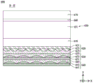
图1是示出根据本公开内容的第一实施方式的光控膜100的截面图。FIG. 1 is a cross-sectional view illustrating a light control film 100 according to a first embodiment of the present disclosure.

参照图1,光控膜100可以包括第一基膜110、透镜部120、视角控制器130、粘合层140和保护膜150。1 , the light control film 100 may include a first base film 110 , a lens part 120 , a viewing angle controller 130 , an adhesive layer 140 and a protective film 150 .

第一基膜110可以包括面向透镜部120的一个表面和面向视角控制器130的另一表面。在形成透镜部120的过程中,第一基膜110的一个表面可以支承透镜部120,并且在形成视角控制器130的过程中,第一基膜110的另一表面可以支承视角控制器130。例如,第一基膜110可以由透明材料形成,并且其上表面和下表面可以各自以平坦结构设置。The first base film 110 may include one surface facing the lens part 120 and the other surface facing the viewing angle controller 130 . In forming the lens part 120 , one surface of the first base film 110 may support the lens part 120 , and in forming the viewing angle controller 130 , the other surface of the first base film 110 may support the viewing angle controller 130 . For example, the first base film 110 may be formed of a transparent material, and the upper and lower surfaces thereof may each be provided in a flat structure.

透镜部120可以设置在第一基膜110的一个表面上,并且可以包括基层121、多个光学图案123和盖层125。The lens part 120 may be disposed on one surface of the first base film 110 and may include a base layer 121 , a plurality of optical patterns 123 and a capping layer 125 .

基层121可以支承多个光学图案123。具体地,基层121可以由与多个光学图案123中的每个的材料相同的材料形成,并且可以提供其中设置有多个光学图案123的基部。也就是说,多个光学图案123中的每个的折射率可以与基层121的折射率相同,并且可以基于多个光学图案123的折射率、形状和布置来确定穿过透镜部120的光的路径。例如,多个光学图案123可以规则地布置以在基层121上形成多个矩阵,或者可以不规则地布置以具有不同的间距。The base layer 121 may support a plurality of optical patterns 123 . Specifically, the base layer 121 may be formed of the same material as that of each of the plurality of optical patterns 123 , and may provide a base in which the plurality of optical patterns 123 are disposed. That is, the refractive index of each of the plurality of optical patterns 123 may be the same as the refractive index of the base layer 121 , and the refractive index of the light passing through the lens part 120 may be determined based on the refractive index, shape and arrangement of the plurality of optical patterns 123 . path. For example, the plurality of optical patterns 123 may be regularly arranged to form a plurality of matrices on the base layer 121, or may be irregularly arranged to have different pitches.

多个光学图案123可以在基层121的上表面中设置为凸图案。例如,多个光学图案123可以以特定间隔隔开,但是不限于此,并且可以设置成彼此相邻。A plurality of optical patterns 123 may be provided in the upper surface of the base layer 121 as convex patterns. For example, the plurality of optical patterns 123 may be spaced apart at certain intervals, but not limited thereto, and may be disposed adjacent to each other.

多个光学图案123中的每个的上表面可以具有诸如拱形的弯曲形状的截面结构,并且多个光学图案123的上表面的截面结构可以相同地设置。此处,可以基于光控膜100的详细配置来修改多个光学图案123的形状和布置,但是本公开内容不限于此。因此,可以根据各种实施方式修改多个光学图案123的形状和布置,以控制穿过透镜部120的光的路径。The upper surface of each of the plurality of optical patterns 123 may have a cross-sectional structure of a curved shape such as an arch, and the cross-sectional structures of the upper surfaces of the plurality of optical patterns 123 may be identically set. Here, the shapes and arrangements of the plurality of optical patterns 123 may be modified based on the detailed configuration of the light control film 100, but the present disclosure is not limited thereto. Accordingly, the shape and arrangement of the plurality of optical patterns 123 may be modified to control the path of light passing through the lens portion 120 according to various embodiments.

根据实施方式,可以确定多个光学图案123的形状和布置,以改善第一方向X和第二方向Y上的基于侧视角的图像。例如,第一方向X可以对应于光控膜100的平面的第一水平方向(例如,宽度方向),并且第二方向Y可以对应于光控膜100的平面的第二水平方向(例如,长度方向)。According to the embodiment, the shape and arrangement of the plurality of optical patterns 123 may be determined to improve the side viewing angle based image in the first direction X and the second direction Y. For example, the first direction X may correspond to a first horizontal direction (eg, the width direction) of the plane of the light control film 100 , and the second direction Y may correspond to a second horizontal direction (eg, the length direction) of the plane of the light control film 100 direction).

根据实施方式,在将材料层涂覆在基层121上之后,可以通过使用印模对材料层加压的工艺来形成多个光学图案123。在这种情况下,印模可以具有与多个光学图案123的形状对应的多个凹图案的形状。根据另一实施方式,多个光学图案123可以与基层121设置为一体。According to an embodiment, after the material layer is coated on the base layer 121 , the plurality of optical patterns 123 may be formed through a process of pressing the material layer using a stamp. In this case, the stamp may have the shape of a plurality of concave patterns corresponding to the shapes of the plurality of optical patterns 123 . According to another embodiment, a plurality of optical patterns 123 may be integrated with the base layer 121 .

在多个光学图案123上可以设置有盖层125。具体地,盖层125可以覆盖多个光学图案123以在多个光学图案123上提供平坦表面。A capping layer 125 may be disposed on the plurality of optical patterns 123 . Specifically, the capping layer 125 may cover the plurality of optical patterns 123 to provide a flat surface on the plurality of optical patterns 123 .

根据实施方式,在将材料层涂覆在第一基膜110的一个表面上之后,可以通过使用印模对材料层加压的工艺来形成盖层125。例如,盖层125可以被雕刻和图案化成与多个光学图案123相对应的形状。此处,材料层可以对应于紫外(UV)树脂或光致抗蚀剂。也就是说,印模可以对盖层125进行雕刻并图案化,以确定与盖层125相对应的多个光学图案123的形状。According to an embodiment, after the material layer is coated on one surface of the first base film 110 , the capping layer 125 may be formed through a process of pressing the material layer using a stamper. For example, the capping layer 125 may be engraved and patterned into a shape corresponding to the plurality of optical patterns 123 . Here, the material layer may correspond to an ultraviolet (UV) resin or a photoresist. That is, the stamp may engrave and pattern the capping layer 125 to determine the shape of the plurality of optical patterns 123 corresponding to the capping layer 125 .

因此,可以在第一基膜110的一个表面中对盖层125进行雕刻和图案化,可以将多个光学图案123设置在基层121的上表面中,并且可以将多个光学图案123接合至盖层125,从而形成透镜部120。Therefore, the cap layer 125 may be engraved and patterned in one surface of the first base film 110, a plurality of optical patterns 123 may be provided in the upper surface of the base layer 121, and the plurality of optical patterns 123 may be bonded to the cap layer 125 , thereby forming the lens portion 120 .

盖层125可以由与多个光学图案123中的每个光学图案不同的材料形成。具体地,盖层125可以由折射率比多个光学图案123中的每个的折射率高的材料形成,或者可以由折射率比多个光学图案123中的每个的折射率低的材料形成。例如,多个光学图案123与盖层125之间的折射率差可以在0.05至0.4的范围内。例如,当多个光学图案123与盖层125之间的折射率差在该范围之外时,可能减少解决显示偏蓝的图像的问题的效果。The capping layer 125 may be formed of a different material from each of the plurality of optical patterns 123 . Specifically, the capping layer 125 may be formed of a material having a higher refractive index than each of the plurality of optical patterns 123 , or may be formed of a material having a lower refractive index than each of the plurality of optical patterns 123 . For example, the refractive index difference between the plurality of optical patterns 123 and the cap layer 125 may be in the range of 0.05 to 0.4. For example, when the refractive index difference between the plurality of optical patterns 123 and the cap layer 125 is outside the range, the effect of solving the problem of displaying a bluish image may be reduced.

如上所述,包括具有透镜部120的光控膜100的显示装置可以解决相对于侧视角显示偏蓝的图像的问题。例如,不包括光控膜100的显示装置可能具有其中相对于侧视角显示偏蓝的图像的问题。因此,根据本公开内容的光控膜100可以耦接至显示面板,以相对于侧视角增加与短波长光相比发射的长波长光的量,并且可以控制在显示面板中出现的偏蓝的图像,从而最终显示高质量的图像。As described above, the display device including the light control film 100 having the lens portion 120 can solve the problem of displaying a bluish image with respect to a side viewing angle. For example, a display device that does not include the light control film 100 may have a problem in which a bluish image is displayed relative to a side viewing angle. Therefore, the light control film 100 according to the present disclosure can be coupled to a display panel to increase the amount of emitted long-wavelength light compared to short-wavelength light with respect to a side viewing angle, and can control the bluishness that occurs in the display panel image, so as to finally display a high-quality image.

视角控制器130可以设置在第一基膜110的另一表面上,并且可以包括多个狭缝133。具体地,视角控制器130可以包括交替地设置在平坦表面上的光透射部分131和光吸收部分,并且光吸收部分可以设置在多个狭缝133中的每个中。The viewing angle controller 130 may be disposed on the other surface of the first base film 110 and may include a plurality of slits 133 . Specifically, the viewing angle controller 130 may include light transmission parts 131 and light absorption parts alternately provided on a flat surface, and the light absorption parts may be provided in each of the plurality of slits 133 .

根据实施方式,在将材料层涂覆在第一基膜110的另一表面上之后,可以通过使用印模对材料层加压的工艺来形成光透射部分131。此处,材料层可以对应于UV树脂或光致抗蚀剂。也就是说,印模可以形成光透射部分131并且可以同时形成与光吸收部分对应的多个狭缝133。因此,印模可以确定与光透射部分131对应的多个狭缝133的形状。另外,光吸收部分可以通过将光吸收材料注入到多个狭缝133中而形成。According to the embodiment, after the material layer is coated on the other surface of the first base film 110 , the light transmitting portion 131 may be formed through a process of pressing the material layer using a stamper. Here, the material layer may correspond to UV resin or photoresist. That is, the stamper may form the light transmitting portion 131 and may simultaneously form a plurality of slits 133 corresponding to the light absorbing portion. Therefore, the stamp can determine the shape of the plurality of slits 133 corresponding to the light transmitting portion 131 . In addition, the light absorbing part may be formed by injecting a light absorbing material into the plurality of slits 133 .

多个狭缝133可以被光透射部分131和粘合层140围绕,并且可以对应于在光透射部分131中以特定间隔设置的凹部。根据实施方式,多个狭缝133可以在第一方向X上延伸并且可以在垂直于第一方向X的第二方向Y上彼此间隔开。例如,第一方向X可以对应于光控膜100的平面的第一水平方向(例如,宽度方向),并且第二方向Y可以对应于光控膜100的平面的第二水平方向(例如,长度方向)。The plurality of slits 133 may be surrounded by the light-transmitting part 131 and the adhesive layer 140 , and may correspond to recesses provided at certain intervals in the light-transmitting part 131 . According to the embodiment, the plurality of slits 133 may extend in the first direction X and may be spaced apart from each other in the second direction Y perpendicular to the first direction X. For example, the first direction X may correspond to a first horizontal direction (eg, the width direction) of the plane of the light control film 100 , and the second direction Y may correspond to a second horizontal direction (eg, the length direction) of the plane of the light control film 100 direction).

根据实施方式,多个狭缝133中的相邻狭缝之间的距离可以是50μm或更小。具体地,当多个狭缝133中的相邻狭缝之间的距离大于50μm时,从显示面板发射的侧光可能不被多个狭缝133阻挡。因此,当在第二方向Y上彼此间隔开的多个狭缝133中的相邻狭缝之间的距离为50μm或更小时,多个狭缝133可以高效地阻挡侧光,从而增强安全性并减少相位显示现象。另外,视角控制器130可以减小相位显示现象以确保室外可见性。According to the embodiment, the distance between adjacent slits among the plurality of slits 133 may be 50 μm or less. Specifically, when the distance between adjacent ones of the plurality of slits 133 is greater than 50 μm, side light emitted from the display panel may not be blocked by the plurality of slits 133 . Therefore, when the distance between adjacent ones of the plurality of slits 133 spaced apart from each other in the second direction Y is 50 μm or less, the plurality of slits 133 can efficiently block side light, thereby enhancing safety And reduce the phase display phenomenon. In addition, the viewing angle controller 130 can reduce the phase display phenomenon to ensure outdoor visibility.

光吸收部分可以包括填充到多个狭缝133中的每个中的光吸收材料。具体地,当光控膜100附接在显示面板上时,光控膜100可以透射从显示面板发射的前光并且可以阻挡(或吸收)侧光。例如,当多个狭缝133沿第一方向X延伸并且在垂直于第一方向X的第二方向Y上彼此间隔开时,视角控制器130可以透射前光和第一方向侧光并且可以阻挡第二方向侧光。The light absorbing part may include a light absorbing material filled into each of the plurality of slits 133 . Specifically, when the light control film 100 is attached on the display panel, the light control film 100 may transmit front light emitted from the display panel and may block (or absorb) side light. For example, when the plurality of slits 133 extend along the first direction X and are spaced apart from each other in the second direction Y perpendicular to the first direction X, the viewing angle controller 130 may transmit the front light and the first direction side light and may block Side light in the second direction.

因此,由于根据本公开内容的光控膜100包括具有多个光学图案123的透镜部120和包括多个狭缝133的视角控制器130,因此可以通过透镜部120改善第一方向X上的基于侧视角的图像,并且视角控制器130可以阻挡第二方向侧光以控制侧视角。Therefore, since the light control film 100 according to the present disclosure includes the lens part 120 having the plurality of optical patterns 123 and the viewing angle controller 130 including the plurality of slits 133 , the based on the first direction X may be improved by the lens part 120 . The image of the side view angle, and the view angle controller 130 may block the second direction side light to control the side view angle.

保护膜150可以通过粘合层140附接在视角控制器130上。例如,保护膜150可以由透明材料形成,并且可以保护光控膜100免受外部冲击。The protective film 150 may be attached on the viewing angle controller 130 through the adhesive layer 140 . For example, the protective film 150 may be formed of a transparent material, and may protect the light control film 100 from external impact.

图2是示出根据本公开内容的第二实施方式的光控膜100的截面图。除了修改透镜部120的配置之外,图2的光控膜与图1的光控膜基本上相同,因此,下面将简要地给出或省略与上述元件相同的元件的描述。FIG. 2 is a cross-sectional view illustrating a light control film 100 according to a second embodiment of the present disclosure. The light control film of FIG. 2 is substantially the same as the light control film of FIG. 1 except that the configuration of the lens portion 120 is modified, and therefore, descriptions of the same elements as those described above will be briefly given or omitted below.

参照图2,透镜部120可以设置在第一基膜110的一个表面上,并且可以包括基层121、多个光学图案123、盖层125和第三基膜127。2 , the lens part 120 may be disposed on one surface of the first base film 110 and may include a base layer 121 , a plurality of optical patterns 123 , a capping layer 125 and a third base film 127 .

基层121可以支承多个光学图案123。具体地,基层121可以由与多个光学图案123中的每个的材料相同的材料形成,并且可以提供其中设置有多个光学图案123的基部。The base layer 121 may support a plurality of optical patterns 123 . Specifically, the base layer 121 may be formed of the same material as that of each of the plurality of optical patterns 123 , and may provide a base in which the plurality of optical patterns 123 are disposed.

多个光学图案123可以在基层121的上表面中设置为凸图案。另外,在多个光学图案123上可以设置有盖层125。具体地,盖层125可以覆盖多个光学图案123以在多个光学图案123上提供平坦表面。A plurality of optical patterns 123 may be provided in the upper surface of the base layer 121 as convex patterns. In addition, a capping layer 125 may be provided on the plurality of optical patterns 123 . Specifically, the capping layer 125 may cover the plurality of optical patterns 123 to provide a flat surface on the plurality of optical patterns 123 .

第三基膜127可以支承基层121和多个光学图案123。具体地,在依次形成基层121、多个光学图案123和盖层125的过程中,第三基膜127可以支承基层121和多个光学图案123。例如,第三基膜127可以由透明材料形成,并且其上表面和下表面可以各自以平坦结构设置。The third base film 127 may support the base layer 121 and the plurality of optical patterns 123 . Specifically, in the process of sequentially forming the base layer 121 , the plurality of optical patterns 123 and the capping layer 125 , the third base film 127 may support the base layer 121 and the plurality of optical patterns 123 . For example, the third base film 127 may be formed of a transparent material, and the upper and lower surfaces thereof may each be provided in a flat structure.

因此,透镜部120可以通过在第三基膜127上依次设置基层121、多个光学图案123和盖层125而形成,并且盖层125可以通过粘合层160附接在第一基膜110的一个表面上。Therefore, the lens part 120 may be formed by sequentially disposing the base layer 121 , the plurality of optical patterns 123 and the capping layer 125 on the third base film 127 , and the capping layer 125 may be attached to the first base film 110 through the adhesive layer 160 . on a surface.

如上所述,根据本公开内容的第二实施方式的光控膜100的特征可以在于,视角控制器130和透镜部120分别设置在第一基膜110的上表面和第三基膜127的下表面上并且通过粘合层160彼此接合。As described above, the light control film 100 according to the second embodiment of the present disclosure may be characterized in that the viewing angle controller 130 and the lens part 120 are disposed on the upper surface of the first base film 110 and the lower surface of the third base film 127, respectively surface and are joined to each other by the adhesive layer 160 .

图3是示出根据本公开内容的第三实施方式的光控膜100的截面图。除了修改透镜部120的配置之外,图3的光控膜与图1和图2中的每个的光控膜基本上相同,因此,下面将简要地给出或省略与上述元件相同的元件的描述。FIG. 3 is a cross-sectional view illustrating a light control film 100 according to a third embodiment of the present disclosure. The light control film of FIG. 3 is substantially the same as the light control film of each of FIGS. 1 and 2 except for the configuration of the modified lens portion 120, therefore, the same elements as those described above will be briefly given or omitted below. description of.

参照图3,透镜部120可以设置在第一基膜110的一个表面上,并且可以包括基层121、多个光学图案123、盖层125和第三基膜127。3 , the lens part 120 may be disposed on one surface of the first base film 110 and may include a base layer 121 , a plurality of optical patterns 123 , a capping layer 125 and a third base film 127 .

基层121可以支承多个光学图案123。具体地,基层121可以由与多个光学图案123中的每个的材料相同的材料形成,并且可以提供其中设置有多个光学图案123的基部。The base layer 121 may support a plurality of optical patterns 123 . Specifically, the base layer 121 may be formed of the same material as that of each of the plurality of optical patterns 123 , and may provide a base in which the plurality of optical patterns 123 are disposed.

多个光学图案123可以在基层121的上表面中设置为凸图案。另外,在多个光学图案123上可以设置有盖层125。具体地,盖层125可以覆盖多个光学图案123以在多个光学图案123上提供平坦表面。A plurality of optical patterns 123 may be provided in the upper surface of the base layer 121 as convex patterns. In addition, a capping layer 125 may be provided on the plurality of optical patterns 123 . Specifically, the capping layer 125 may cover the plurality of optical patterns 123 to provide a flat surface on the plurality of optical patterns 123 .

第三基膜127可以通过粘合层160附接在第一基膜110的一个表面上。例如,第三基膜127可以由透明材料形成,并且其上表面和下表面可以各自以平坦结构设置。The third base film 127 may be attached on one surface of the first base film 110 through the adhesive layer 160 . For example, the third base film 127 may be formed of a transparent material, and the upper and lower surfaces thereof may each be provided in a flat structure.

根据实施方式,在将材料层涂覆在第三基膜127的一个表面上之后,可以通过使用印模对材料层加压的工艺来形成盖层125。例如,盖层125可以被雕刻和图案化成与多个光学图案123相对应的形状。此处,材料层可以对应于UV树脂或光致抗蚀剂。也就是说,印模可以对盖层125进行雕刻并图案化,以确定与盖层125相对应的多个光学图案123的形状。According to an embodiment, after the material layer is coated on one surface of the third base film 127 , the capping layer 125 may be formed through a process of pressing the material layer using a stamp. For example, the capping layer 125 may be engraved and patterned into a shape corresponding to the plurality of optical patterns 123 . Here, the material layer may correspond to UV resin or photoresist. That is, the stamp may engrave and pattern the capping layer 125 to determine the shape of the plurality of optical patterns 123 corresponding to the capping layer 125 .

因此,可以在设置在第一基膜110的一个表面中的第三基膜127的一个表面中对盖层125进行雕刻并图案化,可以将多个光学图案123设置在基层121的上表面中,并且可以将多个光学图案123接合到盖层125,从而形成透镜部120。Therefore, the cap layer 125 may be engraved and patterned in one surface of the third base film 127 disposed in one surface of the first base film 110 , and a plurality of optical patterns 123 may be disposed in the upper surface of the base layer 121 , and a plurality of optical patterns 123 may be bonded to the cap layer 125 , thereby forming the lens part 120 .

如上所述,根据本公开内容的第三实施方式的光控膜100的特征可以在于,视角控制器130设置在第一基膜110的另一表面中,视角控制器130和透镜部120通过粘合层160彼此接合。As described above, the light control film 100 according to the third embodiment of the present disclosure may be characterized in that the viewing angle controller 130 is provided in the other surface of the first base film 110, and the viewing angle controller 130 and the lens part 120 are bonded by The bonding layers 160 are bonded to each other.

图4是示出根据本公开内容的第四实施方式的光控膜100的截面图。除了修改透镜部120和视角控制器130中的每个的配置之外,图4的光控膜与图1至图3中的每个的光控膜基本上相同,因此,下面将简要地给出或省略与上述元件相同的元件的描述。例如,图4的光控膜100可以对应于通过反转图1的光控膜的透镜部120和视角控制器130中的每者的上部和下部来实现的结构。根据实施方式,在图1至图4中的每个中示出的光控膜100中,透镜部120和视角控制器130中的至少一个可以设置为其上部和下部反转的结构。FIG. 4 is a cross-sectional view illustrating a light control film 100 according to a fourth embodiment of the present disclosure. The light control film of FIG. 4 is substantially the same as the light control film of each of FIGS. 1 to 3 except that the configuration of each of the lens section 120 and the viewing angle controller 130 is modified, and therefore, the following will briefly give Descriptions of the same elements as those described above are omitted or omitted. For example, the light control film 100 of FIG. 4 may correspond to a structure realized by reversing the upper and lower portions of each of the lens portion 120 and the viewing angle controller 130 of the light control film of FIG. 1 . According to an embodiment, in the light control film 100 shown in each of FIGS. 1 to 4 , at least one of the lens part 120 and the viewing angle controller 130 may be provided in a structure in which upper and lower parts thereof are reversed.

参照图4,光控膜100可包括第一基膜110、透镜部120、视角控制器130、粘合层140和第二基膜170。可选地,光控膜100还可以包括保护膜150,保护膜150保护第二基膜170的上表面。4 , the light control film 100 may include a first base film 110 , a lens part 120 , a viewing angle controller 130 , an adhesive layer 140 and a second base film 170 . Optionally, the light control film 100 may further include a protective film 150 that protects the upper surface of the second base film 170 .

透镜部120可以设置在第一基膜110的一个表面上,并且可以包括基层121、多个光学图案123和盖层125。The lens part 120 may be disposed on one surface of the first base film 110 and may include a base layer 121 , a plurality of optical patterns 123 and a capping layer 125 .

基层121可以支承多个光学图案123。具体地,基层121可以由与多个光学图案123中的每个的材料相同的材料形成,并且可以提供其中设置有多个光学图案123的基部。The base layer 121 may support a plurality of optical patterns 123 . Specifically, the base layer 121 may be formed of the same material as that of each of the plurality of optical patterns 123, and may provide a base in which the plurality of optical patterns 123 are disposed.

多个光学图案123可以在基层121的下表面中设置为凸图案。另外,在多个光学图案123上可以设置有盖层125。具体地,盖层125可以覆盖多个光学图案123,以在多个光学图案123中的每个的一个表面上提供平坦表面。A plurality of optical patterns 123 may be provided in the lower surface of the base layer 121 as convex patterns. In addition, a capping layer 125 may be provided on the plurality of optical patterns 123 . Specifically, the capping layer 125 may cover the plurality of optical patterns 123 to provide a flat surface on one surface of each of the plurality of optical patterns 123 .

根据实施方式,基层121可以设置在第一基膜110的一个表面中,多个光学图案123可以设置在基层121的一个表面上,并且盖层125可以覆盖多个光学图案123中的每个的一个表面。因此,基层121、多个光学图案123和盖层125可以从第一基膜110的一个表面依次形成。According to an embodiment, the base layer 121 may be disposed on one surface of the first base film 110 , the plurality of optical patterns 123 may be disposed on one surface of the base layer 121 , and the capping layer 125 may cover each of the plurality of optical patterns 123 a surface. Therefore, the base layer 121 , the plurality of optical patterns 123 and the cap layer 125 may be sequentially formed from one surface of the first base film 110 .

如上所述,光控膜100可以包括基层121、多个光学图案123和盖层125,它们依次设置在第一基膜110的一个表面中,从而解决了其中相对于侧视角显示偏蓝的图像的问题。As described above, the light control film 100 may include a base layer 121 , a plurality of optical patterns 123 and a cap layer 125 , which are sequentially disposed in one surface of the first base film 110 , thereby solving an image in which a bluish tint is displayed with respect to a side viewing angle. The problem.

视角控制器130可以设置在第一基膜110的另一表面与第二基膜170的一个表面之间,并且可以包括多个狭缝133。具体地,视角控制器130可以包括交替地设置在平坦表面上的光透射部分131和光吸收部分,并且光吸收部分可以设置在多个狭缝133中的每个中。The viewing angle controller 130 may be disposed between the other surface of the first base film 110 and one surface of the second base film 170 , and may include a plurality of slits 133 . Specifically, the viewing angle controller 130 may include light transmission parts 131 and light absorption parts alternately provided on a flat surface, and the light absorption parts may be provided in each of the plurality of slits 133 .

根据实施方式,在将材料层涂覆在第二基膜170的一个表面上之后,可以通过使用印模对材料层加压的工艺来形成光透射部分131。此处,材料层可以对应于UV树脂或光致抗蚀剂。也就是说,印模可以形成光透射部分131并且可以同时形成与光透射部分131对应的多个狭缝133。因此,印模可以确定与光透射部分131对应的多个狭缝133的形状。另外,光吸收部分可以通过将光吸收材料注入到多个狭缝133中来形成。According to the embodiment, after the material layer is coated on one surface of the second base film 170 , the light transmitting portion 131 may be formed through a process of pressing the material layer using a stamper. Here, the material layer may correspond to UV resin or photoresist. That is, the stamper may form the light transmitting portion 131 and may simultaneously form a plurality of slits 133 corresponding to the light transmitting portion 131 . Therefore, the stamp can determine the shape of the plurality of slits 133 corresponding to the light transmitting portion 131 . In addition, the light absorbing part may be formed by injecting a light absorbing material into the plurality of slits 133 .

如上所述,在将包括光透射部分131的材料的材料层涂覆在第二基膜170的一个表面上之后,可以通过使用印模对材料层加压来形成多个狭缝133,并且角度控制器130可以通过粘合层140附接在第一基膜110的另一表面上。As described above, after the material layer including the material of the light transmitting portion 131 is coated on one surface of the second base film 170, the plurality of slits 133 may be formed by pressing the material layer using a stamp, and the angle The controller 130 may be attached on the other surface of the first base film 110 through the adhesive layer 140 .

此外,光控膜100可以包括视角控制器130,视角控制器130包括面向第一基膜110的另一表面的多个狭缝133,从而改善基于侧视角的图像、增强安全性并减少相位显示现象。In addition, the light control film 100 may include a viewing angle controller 130 including a plurality of slits 133 facing the other surface of the first base film 110, thereby improving images based on side viewing angles, enhancing security, and reducing phase display Phenomenon.

图5A和图5B是示出通过使用根据本公开内容的实施方式的透镜部120以波长为单位调节的光路的示图。FIGS. 5A and 5B are diagrams illustrating optical paths adjusted in units of wavelengths by using the lens portion 120 according to an embodiment of the present disclosure.

参照图5A和图5B,透镜部120可以包括基层121、多个光学图案123和盖层125。5A and 5B , the lens part 120 may include a base layer 121 , a plurality of optical patterns 123 and a capping layer 125 .

在图5A中,基层121和多个光学图案123可以具有比盖层125的折射率低的低折射率,并且盖层125可以具有比基层121和多个光学图案123的每个的折射率高的高折射率。In FIG. 5A , the base layer 121 and the plurality of optical patterns 123 may have a lower refractive index than that of the capping layer 125 , and the capping layer 125 may have a higher refractive index than each of the base layer 121 and the plurality of optical patterns 123 high refractive index.

根据实施方式,入射在透镜部120上的光可以穿过具有相同折射率的多个光学图案123和基层121之间的界面。According to an embodiment, light incident on the lens part 120 may pass through an interface between a plurality of optical patterns 123 having the same refractive index and the base layer 121 .

此外,当光从具有低折射率的多个光学图案123行进到具有高折射率的盖层125时,光的折射形状可以在它们之间的界面中以波长为单位改变。例如,诸如蓝光的短波长光①可以在相对于盖层125的上表面形成第一角度θ1的方向上折射,并且诸如红光的长波长光②可以是在相对于盖层125的上表面形成第二角度θ2的方向上折射。也就是说,短波长光①可以在穿过多个光学图案123与盖层125之间的界面时被折射成比长波长光②更垂直。Furthermore, when light travels from the plurality of optical patterns 123 having a low refractive index to the cap layer 125 having a high refractive index, the refraction shape of the light may change in units of wavelengths in the interface therebetween. For example, short-wavelength light ① such as blue light may be refracted in a direction forming the first angle θ1 with respect to the upper surface of the capping layer 125 , and long-wavelength light ② such as red light may be formed with respect to the upper surface of the capping layer 125 Refraction in the direction of the second angle θ2. That is, the short-wavelength light ① may be refracted to be more perpendicular than the long-wavelength light ② while passing through the interface between the plurality of optical patterns 123 and the cap layer 125 .

此外,均在多个光学图案123与盖层125之间的界面中折射的短波长光①和长波光②可以在盖层125的上表面中再次折射。在这种情况下,盖层125上的部分可以包括折射率比盖层125的折射率低的材料层,因此,短波长光①可以在相对于盖层125的上表面形成第三角度θ3的方向上释放(discharge),并且长波长光②可以在相对于盖层125的上表面形成第四角度θ4上的方向上释放。In addition, the short-wavelength light ① and the long-wavelength light ② each refracted in the interface between the plurality of optical patterns 123 and the capping layer 125 may be refracted again in the upper surface of the capping layer 125 . In this case, the portion on the capping layer 125 may include a material layer with a lower refractive index than that of the capping layer 125 , and therefore, the short-wavelength light ① may form a third angle θ3 with respect to the upper surface of the capping layer 125 direction is discharged, and the long-wavelength light ② may be discharged in a direction forming a fourth angle θ4 with respect to the upper surface of the cap layer 125 .

结果,从盖层125的上表面发射短波长光①的第三角度θ3可以大于从盖层125的上表面发射长波长光②的第四角度θ4。因此,在与侧视角对应的方向上相比于发射的短波长光①的量,根据本公开内容的光控膜100可以增加发射的长波长光②的量,从而防止由显示装置显示的图像变偏蓝的现象。As a result, the third angle θ3 at which the short-wavelength light ① is emitted from the upper surface of the capping layer 125 may be greater than the fourth angle θ4 at which the long-wavelength light ② is emitted from the upper surface of the capping layer 125 . Therefore, the light control film 100 according to the present disclosure can increase the amount of emitted long-wavelength light ② compared to the amount of emitted short-wavelength light ① in the direction corresponding to the side viewing angle, thereby preventing images displayed by the display device The phenomenon of turning blue.

在图5B中,基层121和多个光学图案123可以具有比盖层125的折射率高的高折射率,并且盖层125可以具有比基层121和多个光学图案123的每个的折射率低的低折射率。In FIG. 5B , the base layer 121 and the plurality of optical patterns 123 may have a high refractive index higher than that of the capping layer 125 , and the capping layer 125 may have a lower refractive index than each of the base layer 121 and the plurality of optical patterns 123 low refractive index.

根据实施方式,入射在透镜部120上的光可以穿过具有相同折射率的多个光学图案123和基层121之间的界面。According to an embodiment, light incident on the lens part 120 may pass through an interface between a plurality of optical patterns 123 having the same refractive index and the base layer 121 .

此外,当光从具有高折射率的多个光学图案123行进到具有低折射率的盖层125时,光的折射形状可以在它们之间的界面中以波长为单位改变。具体地,诸如蓝光的短波长光①可以在相对于盖层125的上表面形成第一角度θ1的方向上折射,并且诸如红光的长波长光②可以在相对于盖层125的上表面形成第二角度θ2的方向上折射。也就是说,长波长光②可以在穿过多个光学图案123与盖层125之间的界面时被折射成比短波长光①更垂直。In addition, when light travels from the plurality of optical patterns 123 having a high refractive index to the cap layer 125 having a low refractive index, the refraction shape of the light may change in units of wavelengths in the interface therebetween. Specifically, short-wavelength light ① such as blue light may be refracted in a direction forming the first angle θ1 with respect to the upper surface of the capping layer 125 , and long-wavelength light ② such as red light may be formed relative to the upper surface of the capping layer 125 Refraction in the direction of the second angle θ2. That is, the long-wavelength light ② may be refracted to be more perpendicular than the short-wavelength light ① while passing through the interface between the plurality of optical patterns 123 and the cap layer 125 .

此外,均在多个光学图案123与盖层125之间的界面中折射的短波长光①和长波光②可以在盖层125的上表面中再次折射。在这种情况下,短波长光①与盖层125的上表面之间的第一角度θ1可以较小,并且由此,短波长光①可以不从盖层125的上表面释放到外侧并且可以从盖层125的上表面被全反射。另一方面,长波长光②与盖层125的上表面之间的第二角度θ2可以大于第一角度θ1,因此,长波长光②可以在相对于盖层125的上表面形成第三角度θ3上的方向上发射。In addition, the short-wavelength light ① and the long-wavelength light ② each refracted in the interface between the plurality of optical patterns 123 and the capping layer 125 may be refracted again in the upper surface of the capping layer 125 . In this case, the first angle θ1 between the short-wavelength light ① and the upper surface of the capping layer 125 may be small, and thus, the short-wavelength light ① may not be released from the upper surface of the capping layer 125 to the outside and may It is totally reflected from the upper surface of the cap layer 125 . On the other hand, the second angle θ2 between the long-wavelength light ② and the upper surface of the capping layer 125 may be greater than the first angle θ1 , and thus, the long-wavelength light ② may form a third angle θ3 with respect to the upper surface of the capping layer 125 launch in the direction above.

因此,在与侧视角对应的方向上相比于发射的短波长光①的量,根据本公开内容的光控膜100可以增加发射的长波长光②的量,从而防止出现由显示装置显示的图像变偏蓝的现象。Therefore, the light control film 100 according to the present disclosure can increase the amount of emitted long-wavelength light ② compared to the amount of emitted short-wavelength light ① in the direction corresponding to the side viewing angle, thereby preventing the occurrence of the light displayed by the display device. The phenomenon that the image becomes bluish.

如图5A和图5B所见,根据本公开内容的光控膜100可以适当地调节盖层125和多个光学图案123中的每个的折射率,因此,可以以光波长为单位调节从盖层125的上表面发射的光的量并且可以防止图像相对于侧视角变得偏蓝。也就是说,光控膜100可以在穿过高折射率层与低折射率层之间的界面时使用其中光以光波长为单位具有不同折射图案的特性,从而改善显示装置的图像质量。As seen in FIGS. 5A and 5B , the light control film 100 according to the present disclosure can appropriately adjust the refractive index of the cap layer 125 and each of the plurality of optical patterns 123 , and thus can adjust the index of refraction from the cap layer 125 in units of light wavelengths The amount of light emitted by the upper surface of layer 125 and can prevent the image from becoming bluish with respect to side viewing angles. That is, the light control film 100 may use a characteristic in which light has different refraction patterns in units of light wavelengths when passing through an interface between a high refractive index layer and a low refractive index layer, thereby improving image quality of a display device.

多个光学图案123与盖层125之间的折射率差可以在0.05至0.4的范围内。例如,当多个光学图案123与盖层125之间的折射率差在该范围之外时,由于在图5A的结构中发射的长波长光的量②减少,因此可能仍然保留偏蓝的图像,并且另外,由于在图5B的结构中发射的短波长光①的量增加,所以可能仍然保留偏蓝的图像。The refractive index difference between the plurality of optical patterns 123 and the capping layer 125 may be in the range of 0.05 to 0.4. For example, when the refractive index difference between the plurality of optical patterns 123 and the cap layer 125 is outside this range, since the amount ② of long-wavelength light emitted in the structure of FIG. 5A is reduced, a bluish image may still remain , and in addition, since the amount of emitted short-wavelength light ① is increased in the structure of FIG. 5B , a bluish image may still remain.

如上所述,包括具有透镜部120的光控膜100的显示装置可以解决相对于侧视角显示偏蓝的图像的问题。例如,不包括光控膜100的显示装置可能具有其中相对于侧视角显示偏蓝的图像的问题。因此,根据本公开内容的光控膜100可以耦接至显示面板,以增加相对于侧视角的与短波长光相比发射的长波长光的量,并且可以控制在显示面板中出现的偏蓝的图像,从而最终显示高质量的图像。As described above, the display device including the light control film 100 having the lens portion 120 can solve the problem of displaying a bluish image with respect to a side viewing angle. For example, a display device that does not include the light control film 100 may have a problem in which a bluish image is displayed relative to a side viewing angle. Therefore, the light control film 100 according to the present disclosure can be coupled to a display panel to increase the amount of long wavelength light emitted compared to short wavelength light with respect to a side viewing angle, and can control the bluish cast that occurs in the display panel image, so that the final high-quality image is displayed.

图6是示出根据本公开内容的另一实施方式的透镜部120的截面图。除了修改多个光学图案123中每个的配置之外,图6的透镜部与图1至图4中的每个的透镜部基本上相同。因此,下面将简要地给出或省略与上述元件相同的元件的描述。FIG. 6 is a cross-sectional view illustrating a lens part 120 according to another embodiment of the present disclosure. The lens portion of FIG. 6 is substantially the same as that of each of FIGS. 1 to 4 except that the configuration of each of the plurality of optical patterns 123 is modified. Therefore, descriptions of the same elements as those described above will be briefly given or omitted below.

参照图6,透镜部120可以包括基层121、多个光学图案123和盖层125。6 , the lens part 120 may include a base layer 121 , a plurality of optical patterns 123 and a capping layer 125 .

根据实施方式,多个光学图案123中的每个的表面可以包括设置在中心区域中的平坦表面123a和设置在边缘区域中的弯曲表面123b。也就是说,多个光学图案123中的每个的上表面的一部分可以是平坦表面123a,并且上表面的另一部分可以是弯曲表面123b。According to an embodiment, the surface of each of the plurality of optical patterns 123 may include a flat surface 123a disposed in a central area and a curved surface 123b disposed in an edge area. That is, a portion of the upper surface of each of the plurality of optical patterns 123 may be a flat surface 123a, and another portion of the upper surface may be a curved surface 123b.

由于多个光学图案123中的每个的上表面包括平坦表面123a,因此经由平坦表面123a释放到光控膜100的外部的光量可以增加,因此,可以增强显示装置的亮度。Since the upper surface of each of the plurality of optical patterns 123 includes the flat surface 123a, the amount of light released to the outside of the light control film 100 via the flat surface 123a can be increased, and thus, the brightness of the display device can be enhanced.

图7是示出根据本公开内容的实施方式的透镜部的多个光学图案123的平面图。FIG. 7 is a plan view illustrating a plurality of optical patterns 123 of the lens portion according to an embodiment of the present disclosure.

参照图7,在基层121上可以设置有多个光学图案123。多个光学图案123中的每个可以设置成一维圆形结构,但是不限于此,并且可以设置成椭圆形结构。根据情况,多个光学图案123中的每个可以设置成多边形结构诸如五边形结构或六边形结构。Referring to FIG. 7 , a plurality of optical patterns 123 may be disposed on the base layer 121 . Each of the plurality of optical patterns 123 may be arranged in a one-dimensional circular structure, but is not limited thereto, and may be arranged in an elliptical structure. According to circumstances, each of the plurality of optical patterns 123 may be arranged in a polygonal structure such as a pentagonal structure or a hexagonal structure.

根据实施方式,多个光学图案123的下表面的直径D可以相同,因此,多个光学图案123可以具有相同的尺寸。在这种情况下,多个光学图案123中的每个的下表面的直径D可以是20μm或更小。例如,当多个光学图案123中的每个的下表面的直径D大于20μm时,可能无法获得根据本公开内容的以光波长为单位的改变光路的效果。因此,多个光学图案123之间的间距P可以相同,并且因此,多个光学图案123可以规则地布置以形成多个矩阵。According to the embodiment, the diameters D of the lower surfaces of the plurality of optical patterns 123 may be the same, and thus, the plurality of optical patterns 123 may have the same size. In this case, the diameter D of the lower surface of each of the plurality of optical patterns 123 may be 20 μm or less. For example, when the diameter D of the lower surface of each of the plurality of optical patterns 123 is larger than 20 μm, the effect of changing the optical path in units of light wavelengths according to the present disclosure may not be obtained. Accordingly, the pitches P between the plurality of optical patterns 123 may be the same, and thus, the plurality of optical patterns 123 may be regularly arranged to form a plurality of matrices.

图8是示出根据本公开内容的另一实施方式的透镜部的多个光学图案123的平面图。FIG. 8 is a plan view illustrating a plurality of optical patterns 123 of a lens part according to another embodiment of the present disclosure.

参照图8,多个光学图案123可以具有不同的直径D1和D2,并且可以以不同的间距P1至P5不规则地布置。8, the plurality of optical patterns 123 may have different diameters D1 and D2, and may be irregularly arranged at different pitches P1 to P5.

例如,一个光学图案123的下表面的第一直径D1可以与另一个光学图案123的下表面的第二直径D2不同。也就是说,多个光学图案123中的至少两个可以包括具有不同尺寸的下表面。另外,相对于一个光学图案123,在与其相邻的其他光学图案123与该一个光学图案123之间的第一间距P1至第五间距P5中的至少两个可以不同。For example, the first diameter D1 of the lower surface of one optical pattern 123 may be different from the second diameter D2 of the lower surface of the other optical pattern 123 . That is, at least two of the plurality of optical patterns 123 may include lower surfaces having different sizes. In addition, with respect to one optical pattern 123, at least two of the first to fifth pitches P1 to P5 between the other optical pattern 123 adjacent thereto and the one optical pattern 123 may be different.

如上所述,多个光学图案123可以具有不同的直径D1和D2,并且可以以不同的间距P1至P5不规则地布置,从而减少莫尔条纹现象。As described above, the plurality of optical patterns 123 may have different diameters D1 and D2, and may be irregularly arranged at different pitches P1 to P5, thereby reducing the moire phenomenon.

图9是示出在显示面板上设置有根据本公开内容的实施方式的透镜部的多个光学图案的情况下的光路的图。FIG. 9 is a diagram illustrating an optical path in a case where a plurality of optical patterns of a lens portion according to an embodiment of the present disclosure are provided on a display panel.

参照图9,显示面板可以包括多个像素,并且多个像素中的每个可以包括多个子像素SP。另外,多个子像素SP中的每个可以包括开口区域OA和非开口区域NOA。Referring to FIG. 9 , the display panel may include a plurality of pixels, and each of the plurality of pixels may include a plurality of sub-pixels SP. In addition, each of the plurality of sub-pixels SP may include an open area OA and a non-open area NOA.

每个子像素SP的非开口区域NOA可以不发光。从每个子像素SP的开口区域OA发射的光可以在穿过透镜部120时被折射,因此,输出范围可以被扩大到与非开口区域NOA对应的区域。此处,可以在多个光学图案123上设置折射率比多个光学图案123中的每个的折射率小的空气层。例如,多个光学图案123中的每个的折射率可以为1.5至1.6,并且空气层的折射率可以为1,但是本公开内容不限于此。The non-open area NOA of each sub-pixel SP may not emit light. The light emitted from the opening area OA of each sub-pixel SP may be refracted while passing through the lens part 120, and thus, the output range may be expanded to the area corresponding to the non-opening area NOA. Here, an air layer having a refractive index smaller than that of each of the plurality of optical patterns 123 may be provided on the plurality of optical patterns 123 . For example, the refractive index of each of the plurality of optical patterns 123 may be 1.5 to 1.6, and the refractive index of the air layer may be 1, but the present disclosure is not limited thereto.

也就是说,在人眼不可见的方向上的光输出可以穿过每个子像素SP的开口区域OA中的多个光学图案123,因此,由于多个光学图案123与多个光学图案123上的空气层之间的折射率差异,光可以在竖直方向上折射,并且可以从与非开口区域NOA以及开口区域OA对应的区域输出。如上所述,在从与每个子像素SP的非开口区域NOA对应的区域输出可见光的情况下,可以在对应区域中设置伪像素。因此,每个子像素SP的输出范围可以被扩大到与非开口区域NOA对应的区域。That is, the light output in the direction invisible to the human eye may pass through the plurality of optical patterns 123 in the opening area OA of each sub-pixel SP, therefore, due to the difference between the plurality of optical patterns 123 and the plurality of optical patterns 123 Due to the difference in refractive index between the air layers, light can be refracted in the vertical direction, and can be output from regions corresponding to the non-open area NOA and the open area OA. As described above, in the case where visible light is output from the area corresponding to the non-aperture area NOA of each sub-pixel SP, dummy pixels may be provided in the corresponding area. Therefore, the output range of each sub-pixel SP can be expanded to the area corresponding to the non-aperture area NOA.

此外,从开口区域OA发射的光可以穿过多个光学图案123,因此,通过衍射可以更大地扩大输出范围。In addition, the light emitted from the opening area OA may pass through the plurality of optical patterns 123, and thus, the output range may be more enlarged by diffraction.

因此,在从每个子像素SP的开口区域OA输出的光穿过多个光学图案123的情况下,可以通过调节光路从与每个子像素SP的非开口区域NOA对应的区域输出可见光,因此,可以减小与子像素SP的非开口区域NOA对应的区域彼此连接并且被识别为格子形式的格子灵敏度,并且可以保持锐利的图像。Therefore, in the case where the light output from the opening area OA of each sub-pixel SP passes through the plurality of optical patterns 123, visible light can be output from the area corresponding to the non-opening area NOA of each sub-pixel SP by adjusting the optical path, and thus, it is possible to The lattice sensitivity in which the regions corresponding to the non-opening regions NOA of the sub-pixels SP are connected to each other and recognized as lattice forms is reduced, and a sharp image can be maintained.

因此,光控膜100可以有效地降低虚拟现实(VR)装置的格子灵敏度,这使得用户在眼睛靠近屏幕的状态下观看图像,并且另外,可以有效地减少其中图像是模糊的图像模糊。Therefore, the light control film 100 can effectively reduce the lattice sensitivity of a virtual reality (VR) device, which allows the user to view images with eyes close to the screen, and in addition, can effectively reduce image blurring in which the image is blurred.

图10A是示出在显示面板上设置有根据本公开内容的实施方式的透镜部120的示例的截面图。10A is a cross-sectional view illustrating an example in which the lens part 120 according to an embodiment of the present disclosure is provided on a display panel.

参照图10A,显示面板可以包括多个像素,并且多个像素中的每个可以包括多个子像素SP。另外,多个子像素SP中的每个可以包括开口区域OA和非开口区域NOA。Referring to FIG. 10A , the display panel may include a plurality of pixels, and each of the plurality of pixels may include a plurality of sub-pixels SP. In addition, each of the plurality of sub-pixels SP may include an open area OA and a non-open area NOA.

透镜部120可以设置在显示面板上,并且可以包括基层121、多个光学图案123和盖层125。The lens part 120 may be disposed on the display panel, and may include a base layer 121 , a plurality of optical patterns 123 and a capping layer 125 .

基层121和多个光学图案123可以均具有第一折射率,并且盖层125可以具有小于第一折射率的第二折射率。例如,第一折射率可以为1.5至1.6,并且第二折射率可以为1.1至1.4,但是本公开内容不限于此。根据实施方式,多个光学图案123与盖层125之间的折射率差可以在0.05至0.4的范围内。例如,当多个光学图案123与盖层125之间的折射率差在该范围之外时,可能减少解决显示偏蓝的图像的问题的效果。The base layer 121 and the plurality of optical patterns 123 may each have a first refractive index, and the capping layer 125 may have a second refractive index smaller than the first refractive index. For example, the first refractive index may be 1.5 to 1.6, and the second refractive index may be 1.1 to 1.4, but the present disclosure is not limited thereto. According to the embodiment, the refractive index difference between the plurality of optical patterns 123 and the capping layer 125 may be in the range of 0.05 to 0.4. For example, when the refractive index difference between the plurality of optical patterns 123 and the cap layer 125 is outside the range, the effect of solving the problem of displaying a bluish image may be reduced.

根据实施方式,基层121和多个光学图案123可以由树脂形成。例如,基层121和多个光学图案123可以由聚对苯二甲酸乙二醇酯(PET)、聚碳酸酯(PC)或丙烯酸材料形成,但不限于此。According to an embodiment, the base layer 121 and the plurality of optical patterns 123 may be formed of resin. For example, the base layer 121 and the plurality of optical patterns 123 may be formed of polyethylene terephthalate (PET), polycarbonate (PC), or acrylic material, but are not limited thereto.

此外,为了防止来自每个子像素SP的光输出被输出到多个光学图案123之间的空白空间并且被识别为颜色分散,多个光学图案123中的每个的下表面的直径D可以被设定为大于多个光学图案123之间的间隔距离d。例如,多个光学图案123中的每个的下表面的直径D可以为20μm或更小,并且多个光学图案123之间的间隔距离d可以为5μm或更小,但是本公开内容不限于此。In addition, in order to prevent the light output from each sub-pixel SP from being output to the empty space between the plurality of optical patterns 123 and being recognized as color dispersion, the diameter D of the lower surface of each of the plurality of optical patterns 123 may be set to It is set to be larger than the interval distance d between the plurality of optical patterns 123 . For example, the diameter D of the lower surface of each of the plurality of optical patterns 123 may be 20 μm or less, and the spacing distance d between the plurality of optical patterns 123 may be 5 μm or less, but the present disclosure is not limited thereto .

因此,附接在显示面板上的透镜部120可以锐利地保持由显示面板显示的图像,并且为了使格子灵敏度不可见,可以将多个光学图案123中的每个的高度H设置为大于下表面的直径D。例如,多个光学图案123中的每个的下表面的高度H与直径D的比率可以对应于1至2,但是不限于此。Therefore, the lens part 120 attached to the display panel can sharply maintain the image displayed by the display panel, and in order to make the lattice sensitivity invisible, the height H of each of the plurality of optical patterns 123 can be set to be larger than the lower surface diameter D. For example, the ratio of the height H to the diameter D of the lower surface of each of the plurality of optical patterns 123 may correspond to 1 to 2, but is not limited thereto.

图10B是示出在显示面板上设置有根据本公开内容的实施方式的透镜部的情况下的光路的图。FIG. 10B is a diagram illustrating an optical path in a case where a lens portion according to an embodiment of the present disclosure is provided on a display panel.

参照图10B,每个子像素SP的非开口区域NOA可以不发光。从每个子像素SP的开口区域OA发射的光可以在穿过透镜部120的同时被折射,因此,输出范围可以被扩大到与非开口区域NOA对应的区域。此处,在多个光学图案123上可以设置有折射率比多个光学图案123中的每个的折射率小的空气层。Referring to FIG. 10B , the non-aperture area NOA of each sub-pixel SP may not emit light. The light emitted from the opening area OA of each sub-pixel SP may be refracted while passing through the lens part 120, and thus, the output range may be expanded to the area corresponding to the non-opening area NOA. Here, an air layer having a refractive index smaller than that of each of the plurality of optical patterns 123 may be provided on the plurality of optical patterns 123 .

也就是说,在人眼不可见的方向上的光输出可以穿过每个子像素SP的开口区域OA中的多个光学图案123,因此,由于多个光学图案123与多个光学图案123上的空气层之间的折射率差异,光可以在竖直方向上折射,并且可以从与非开口区域NOA以及开口区域OA对应的区域输出。如上所述,在从与每个子像素SP的非开口区域NOA对应的区域输出可见光的情况下,可以在对应区域中设置伪像素。因此,每个子像素SP的输出范围可以被扩大到与非开口区域NOA对应的区域。That is, the light output in the direction invisible to the human eye may pass through the plurality of optical patterns 123 in the opening area OA of each sub-pixel SP, therefore, due to the difference between the plurality of optical patterns 123 and the plurality of optical patterns 123 Due to the difference in refractive index between the air layers, light can be refracted in the vertical direction, and can be output from regions corresponding to the non-open area NOA and the open area OA. As described above, in the case where visible light is output from the area corresponding to the non-aperture area NOA of each sub-pixel SP, dummy pixels may be provided in the corresponding area. Therefore, the output range of each sub-pixel SP can be expanded to the area corresponding to the non-aperture area NOA.

此外,从开口区域OA发射的光可以穿过多个光学图案123,因此,通过衍射可以更大地扩大输出范围。In addition, the light emitted from the opening area OA may pass through the plurality of optical patterns 123, and thus, the output range may be more enlarged by diffraction.

因此,在从每个子像素SP的开口区域OA输出的光穿过多个光学图案123的情况下,可以通过调节光路从与每个子像素SP的非开口区域NOA对应的区域输出可见光,因此,可以减小与子像素SP的非开口区域NOA对应的区域彼此连接并且被识别为格子形式的格子灵敏度,并且可以保持锐利的图像。Therefore, in the case where the light output from the opening area OA of each sub-pixel SP passes through the plurality of optical patterns 123, visible light can be output from the area corresponding to the non-opening area NOA of each sub-pixel SP by adjusting the optical path, and thus, it is possible to The lattice sensitivity in which the regions corresponding to the non-opening regions NOA of the sub-pixels SP are connected to each other and recognized as lattice forms is reduced, and a sharp image can be maintained.

因此,光控膜100可以有效地降低VR装置的格子灵敏度,这使得用户在眼睛靠近屏幕的状态下观看图像,并且另外,可以有效地减少其中图像是模糊的图像模糊。Therefore, the light control film 100 can effectively reduce the lattice sensitivity of the VR device, which enables the user to view images with eyes close to the screen, and in addition, can effectively reduce image blur in which the image is blurred.

图11是示出在显示面板上设置有根据本公开内容的实施方式的光控膜100的情况下的光路的图。FIG. 11 is a diagram illustrating an optical path in a case where the light control film 100 according to an embodiment of the present disclosure is provided on a display panel.

参照图11,光控膜100可以包括设置在第一基膜110的一个表面上的透镜部120和设置在第一基膜110的另一表面上的视角控制器130。11 , the light control film 100 may include a lens part 120 disposed on one surface of the first base film 110 and a viewing angle controller 130 disposed on the other surface of the first base film 110 .

从子像素SP的开口区域OA发射的光可以入射在透镜部120上,并且可见光可以输出到与在第一方向X和第二方向Y上与开口区域OA相邻的非开口区域NOA对应的区域。因此,光控膜100可以降低其中与在第一方向X和第二方向Y上与开口区域OA相邻的非开口区域NOA对应的区域彼此连接并且被识别为格子形式的格子灵敏度,这可以减少并且可以保持清晰的图像。Light emitted from the opening area OA of the sub-pixel SP may be incident on the lens part 120, and visible light may be output to an area corresponding to the non-opening area NOA adjacent to the opening area OA in the first direction X and the second direction Y . Therefore, the light control film 100 can reduce the lattice sensitivity in which the regions corresponding to the non-opening regions NOA adjacent to the opening regions OA in the first and second directions X and Y are connected to each other and are recognized as lattices, which can reduce And can maintain a clear image.

此外,视角控制器130可以被设置成与透镜部120交叠,并且从透镜部120输出的光可以入射在视角控制器130上。在这种情况下,视角控制器130可以包括多个狭缝133,其在第一方向X上延伸并且在垂直于第一方向X的第二方向Y上彼此间隔开,并且光吸收部分可以被设置在多个狭缝133中的每个中。光吸收部分可以透射在第一方向X上输出的侧光,并且可以阻挡在第二方向Y上输出的侧光。Also, the viewing angle controller 130 may be disposed to overlap the lens part 120 , and light output from the lens part 120 may be incident on the viewing angle controller 130 . In this case, the viewing angle controller 130 may include a plurality of slits 133 extending in the first direction X and spaced apart from each other in the second direction Y perpendicular to the first direction X, and the light absorbing part may be provided in each of the plurality of slits 133 . The light absorbing part may transmit the side light output in the first direction X, and may block the side light output in the second direction Y.

因此,透镜部120可以改善基于第一方向X上的侧视角的图像,并且视角控制器130可以阻挡在第二方向Y上的侧光,从而防止相对于第一方向X上的侧视角显示偏蓝的图像,增强了在第二方向Y上的安全性,并减少了相位显示现象。Therefore, the lens part 120 can improve the image based on the side viewing angle in the first direction X, and the viewing angle controller 130 can block the side light in the second direction Y, thereby preventing the display from being skewed with respect to the side viewing angle in the first direction X The blue image enhances the security in the second direction Y and reduces the phase display phenomenon.

图12是示出根据本公开内容的实施方式的显示装置的截面图,图13是示出根据本公开内容的另一实施方式的显示装置的截面图,以及图14是示出根据本公开内容的另一实施方式的显示装置的截面图。12 is a cross-sectional view illustrating a display device according to an embodiment of the present disclosure, FIG. 13 is a cross-sectional view illustrating a display device according to another embodiment of the present disclosure, and FIG. 14 is a cross-sectional view illustrating a display device according to the present disclosure A cross-sectional view of a display device according to another embodiment of the present invention.

参照图12至图14,根据本公开内容的实施方式的显示装置可以包括光控膜100、显示面板200、偏振膜300和触摸面板400。12 to 14 , a display device according to an embodiment of the present disclosure may include a light control film 100 , a display panel 200 , a polarizing film 300 and a touch panel 400 .

显示面板200可以显示图像。在显示面板200上可以设置有偏振膜300。在偏振膜300上可以设置有触摸面板400。The display panel 200 may display images. A polarizing film 300 may be provided on the display panel 200 . A touch panel 400 may be provided on the polarizing film 300 .

偏振膜300可以防止显示装置的性能因由显示面板200发出的光与从外部输入并被内部反射器反射的外部自然光(外部光)之间的干涉而降低。偏振器的吸收轴和相位差补偿膜的光轴(吸收轴)可以对准以倾斜,因此,由内部反射器反射的外部光的波形可以旋转,由此偏振膜300可以具有抗反射滤光器的功能。The polarizing film 300 can prevent the performance of the display device from being lowered due to interference between light emitted from the display panel 200 and external natural light (external light) input from the outside and reflected by the internal reflector. The absorption axis of the polarizer and the optical axis (absorption axis) of the retardation compensation film can be aligned to be inclined, and therefore, the waveform of the external light reflected by the internal reflector can be rotated, whereby the polarizing film 300 can have an anti-reflection filter function.

触摸面板400可以感测用户触摸以实现对话和直观操作,并且因此可以用作使得能够容易地操纵显示装置和包括显示装置的电子装置的输入装置。The touch panel 400 can sense user touch to realize dialogue and intuitive operation, and thus can be used as an input device enabling easy manipulation of a display device and an electronic device including the display device.

光控膜100可以设置在显示面板200与偏振膜300之间、偏振膜300与触摸面板400之间、和/或触摸面板400的上表面中,从而提供上述效果。The light control film 100 may be disposed between the display panel 200 and the polarizing film 300 , between the polarizing film 300 and the touch panel 400 , and/or in the upper surface of the touch panel 400 to provide the above effects.

图15是示出根据本公开内容的实施方式的显示装置的平面图。FIG. 15 is a plan view illustrating a display device according to an embodiment of the present disclosure.

参照图15,显示装置可以包括光控膜100、显示面板200和显示驱动电路单元500。15 , the display device may include a light control film 100 , a display panel 200 and a display driving circuit unit 500 .

光控膜100可以设置在显示面板200的前表面上。另外,光控膜100可以被设置成与显示面板200的显示区AA交叠。根据实施方式,光控膜100可以通过粘合构件附接在显示面板200上,或者可以与显示面板200设置为一体。The light control film 100 may be disposed on the front surface of the display panel 200 . In addition, the light control film 100 may be disposed to overlap the display area AA of the display panel 200 . According to the embodiment, the light control film 100 may be attached on the display panel 200 through an adhesive member, or may be provided integrally with the display panel 200 .

光控膜100可以包括视角控制器130,视角控制器130包括多个狭缝133。具体地,视角控制器130可以包括交替地设置在平坦表面上的光透射部分131和光吸收部分,并且光吸收部分可以设置在多个狭缝133中的每个中。The light control film 100 may include a viewing angle controller 130 including a plurality of slits 133 . Specifically, the viewing angle controller 130 may include light transmission parts 131 and light absorption parts alternately provided on a flat surface, and the light absorption parts may be provided in each of the plurality of slits 133 .

根据实施方式,多个狭缝133可以在第一方向X上延伸并且可以在垂直于第一方向X的第二方向Y上彼此间隔开。例如,第一方向X可以对应于光控膜100的平面的第一水平方向(例如,宽度方向),并且第二方向Y可以对应于光控膜100的平面的第二水平方向(例如,长度方向)。According to the embodiment, the plurality of slits 133 may extend in the first direction X and may be spaced apart from each other in the second direction Y perpendicular to the first direction X. For example, the first direction X may correspond to a first horizontal direction (eg, the width direction) of the plane of the light control film 100 , and the second direction Y may correspond to a second horizontal direction (eg, the length direction) of the plane of the light control film 100 direction).

光吸收部分可以包括填充到多个狭缝133中的每个中的光吸收材料。例如,当多个狭缝133沿第一方向X延伸并且在垂直于第一方向X的第二方向Y上彼此间隔开时,视角控制器130可以透射前光和第一方向侧光并且可以阻挡第二方向侧光。因此,光控膜100可以耦接至显示面板200,因此,光控膜100可以透射从显示面板200发射的前光和在第一方向X上发射的侧光并且可以阻挡(或者吸收)在第二方向Y上发射的侧光。The light absorbing part may include a light absorbing material filled into each of the plurality of slits 133 . For example, when the plurality of slits 133 extend along the first direction X and are spaced apart from each other in the second direction Y perpendicular to the first direction X, the viewing angle controller 130 may transmit the front light and the first direction side light and may block Side light in the second direction. Therefore, the light control film 100 may be coupled to the display panel 200, and thus, the light control film 100 may transmit the front light emitted from the display panel 200 and the side light emitted in the first direction X and may block (or absorb) Side light emitted in two directions Y.

如上所述,光控膜100可以耦接至显示面板200以增加相对于侧视角的与短波长光相比发射的长波长光的量,并且可以控制在显示面板200中出现的偏蓝的图像,从而最终显示高质量图像。As described above, the light control film 100 can be coupled to the display panel 200 to increase the amount of long-wavelength light emitted compared to short-wavelength light with respect to a side viewing angle, and can control a bluish image that appears in the display panel 200 , which ultimately displays a high-quality image.

此外,光控膜100可以耦接至显示面板200,因此,光控膜100可以透射从显示面板200发射的前光并且可以阻挡(或吸收)侧光。例如,当多个狭缝133在第一方向X上延伸并且在垂直于第一方向X的第二方向Y上彼此间隔开时,视角控制器130可以透射前光和第一方向侧光并且可以阻挡第二方向侧光。Also, the light control film 100 may be coupled to the display panel 200, and thus, the light control film 100 may transmit front light emitted from the display panel 200 and may block (or absorb) side light. For example, when the plurality of slits 133 extend in the first direction X and are spaced apart from each other in the second direction Y perpendicular to the first direction X, the viewing angle controller 130 may transmit the front light and the first direction side light and may Block the second direction side light.

显示面板200可以包括显示区AA和非显示区NA。显示区AA可以是显示图像的区域,并且可以对应于显示面板200的中心部分。非显示区NA可以是不显示图像的区域,并且可以对应于显示面板200的围绕显示区AA的边缘部分。例如,显示面板200可以使用所有类型的显示面板,诸如液晶显示面板、有机发光二极管(OLED)显示面板和电致发光显示面板。The display panel 200 may include a display area AA and a non-display area NA. The display area AA may be an area where an image is displayed, and may correspond to a central portion of the display panel 200 . The non-display area NA may be an area where no image is displayed, and may correspond to an edge portion of the display panel 200 surrounding the display area AA. For example, the display panel 200 may use all types of display panels such as a liquid crystal display panel, an organic light emitting diode (OLED) display panel, and an electroluminescence display panel.

显示驱动电路单元500可以包括多个电路膜510、多个驱动集成电路(IC)530、印刷电路板(PCB)550和定时控制器570。The display driving circuit unit 500 may include a plurality of circuit films 510 , a plurality of driving integrated circuits (ICs) 530 , a printed circuit board (PCB) 550 and a timing controller 570 .

多个电路膜510中的每个可以附接在显示面板200和PCB 550的焊盘部分上。例如,设置在多个电路膜510中的每个的一侧中的输入端子可以通过膜附接工艺附接在PCB 550上,并且设置在多个电路膜510中的每个的另一侧中的输出端子可以通过膜附接工艺附接在显示面板200的焊盘部分上。Each of the plurality of circuit films 510 may be attached on the display panel 200 and the pad portion of the PCB 550 . For example, an input terminal provided in one side of each of the plurality of circuit films 510 may be attached on the PCB 550 through a film attaching process, and provided in the other side of each of the plurality of circuit films 510 The output terminals of the can be attached on the pad portion of the display panel 200 through a film attachment process.

多个驱动IC 530中的每个可以单独地安装在多个电路膜510的相应电路膜上。多个驱动IC 530中的每个可以接收每个从定时控制器570提供的数据控制信号和像素数据,根据数据控制信号将像素数据转换为基于像素的模拟数据信号,并且将模拟数据信号提供至相应的数据线。Each of the plurality of driving ICs 530 may be individually mounted on the corresponding circuit film of the plurality of circuit films 510 . Each of the plurality of driver ICs 530 may receive a data control signal and pixel data each provided from the timing controller 570, convert the pixel data into pixel-based analog data signals according to the data control signals, and provide the analog data signals to corresponding data line.

PCB 550可以支持定时控制器570,并且可以在显示驱动电路单元500的元件之间传输信号和电力。The PCB 550 may support the timing controller 570 and may transmit signals and power between elements of the display driving circuit unit 500 .

定时控制器570可以安装在PCB 550上,并且可以通过设置在PCB 550上的用户连接器接收均从显示驱动系统提供的视频数据和定时同步信号。另外,定时控制器570可以基于定时同步信号生成数据控制信号和扫描控制信号,通过使用数据控制信号控制多个驱动IC 530中的每个的驱动定时,并且通过使用扫描控制信号控制栅极驱动电路单元的驱动定时。The timing controller 570 may be mounted on the PCB 550 and may receive video data and timing synchronization signals both provided from the display driving system through a user connector provided on the PCB 550 . In addition, the timing controller 570 may generate a data control signal and a scan control signal based on the timing synchronization signal, control the driving timing of each of the plurality of driving ICs 530 by using the data control signal, and control the gate driving circuit by using the scan control signal The drive timing of the unit.

图16A和16B是示出在根据本公开内容的实施方式的显示装置中改善基于侧视角的图像的示例的图。此处,图16A示出了包括不具有透镜部120的光控膜100的显示装置的观看亮度,以及图16B示出了包括根据本公开内容的光控膜100的显示装置的观看亮度。另外,在图16A和图16B中,第一角度θ1可以对应于沿X方向和Y方向设置的平面的角度,并且第二角度θ2可以对应于沿X方向和Z方向设置的平面的角度。此外,亮度可以在更接近区域A+的方向上对应于高亮度,并且亮度可以在更接近区域B的方向上对应于低亮度。16A and 16B are diagrams illustrating an example of improving an image based on a side viewing angle in a display device according to an embodiment of the present disclosure. Here, FIG. 16A shows the viewing brightness of the display device including the light control film 100 without the lens portion 120 , and FIG. 16B shows the viewing brightness of the display device including the light control film 100 according to the present disclosure. In addition, in FIGS. 16A and 16B , the first angle θ1 may correspond to the angle of the plane arranged in the X direction and the Y direction, and the second angle θ2 may correspond to the angle of the plane arranged in the X direction and the Z direction. Further, the luminance may correspond to high luminance in a direction closer to the area A+, and the luminance may correspond to low luminance in a direction closer to the area B.

参照图16A,当显示面板200简单地耦接至不包括透镜部120的光控膜100时,可能发生莫尔条纹现象,导致图像质量劣化。因此,包括不具有透镜部120的光控膜100的显示装置可能被设定在光控膜100与显示面板200之间的偏置角,以便改善基于侧视角的图像。当设定光控膜100与显示面板200之间的偏置角时,可能出现相对于侧视场的在四个角部中的至少一个角部处亮度显著降低的问题。Referring to FIG. 16A, when the display panel 200 is simply coupled to the light control film 100 not including the lens part 120, a moire phenomenon may occur, resulting in image quality degradation. Therefore, a display device including the light control film 100 without the lens portion 120 may be set at an offset angle between the light control film 100 and the display panel 200 in order to improve an image based on a side viewing angle. When the offset angle between the light control film 100 and the display panel 200 is set, there may be a problem that luminance is significantly reduced at at least one of the four corners with respect to the side viewing field.

例如,在图16A中所示的观看亮度中,可以看出,由于设定了控制膜100与显示面板200之间的偏置角,因此在平面方向在上左上角部(θ1:150度)的亮度显著降低。因此,图16A的显示装置具有显示偏蓝的图像的问题,因为诸如蓝光的发射的短波长光的量相对于平面方向上的左上角部(θ1:150度)的侧视角增加。另外,由于出现左侧与右侧之间的视角差,因此显示装置具有发生色移的问题。For example, in the viewing luminance shown in FIG. 16A , it can be seen that since the offset angle between the control film 100 and the display panel 200 is set, the upper left corner (θ1: 150 degrees) is in the upper left corner in the plane direction. The brightness is significantly reduced. Therefore, the display device of FIG. 16A has a problem of displaying a bluish image because the amount of emitted short-wavelength light such as blue light increases with respect to the side viewing angle of the upper left corner portion (θ1: 150 degrees) in the planar direction. In addition, the display device has a problem that color shift occurs due to the occurrence of a difference in viewing angle between the left side and the right side.

参照图16B,根据本公开内容的包括光控膜100的显示装置可以包括:透镜部120,包括多个光学图案123;以及视角控制器130,包括多个狭缝133。因此,即使没有设定在光控膜100与显示面板200之间的偏置角,显示装置也可以防止出现莫尔条纹现象。换言之,即便在如VR类型的显示装置中那样接近观看时,由于子像素之间的空间引起的视觉栅格线也可以相对于观看者被隐藏并且可以提高图像质量。16B , the display device including the light control film 100 according to the present disclosure may include: a lens part 120 including a plurality of optical patterns 123 ; and a viewing angle controller 130 including a plurality of slits 133 . Therefore, even if the offset angle between the light control film 100 and the display panel 200 is not set, the display device can prevent the moire phenomenon from occurring. In other words, even when viewed in close proximity as in a VR type display device, visual grid lines due to spaces between sub-pixels can be hidden from the viewer and image quality can be improved.

由于没有设定在光控膜100与显示面板200之间的偏置角,因此根据本公开内容的显示装置可以相对于侧视场在四个角部中具有均匀的亮度。另外,根据本公开内容的显示装置可以增加诸如红光的发射的长波长光的量以防止显示偏蓝的图像,并且可以去除左侧与右侧之间的视角差异以防止发生色移。Since there is no offset angle set between the light control film 100 and the display panel 200, the display device according to the present disclosure may have uniform brightness in four corners with respect to a side viewing field. In addition, the display device according to the present disclosure can increase the amount of emitted long-wavelength light such as red light to prevent a bluish image from being displayed, and can remove the difference in viewing angle between left and right sides to prevent color shift.

另外,根据本公开内容的显示装置可以包括透镜部120和视角控制器130,因此,可以不需要用于改善图像的附加膜。In addition, the display device according to the present disclosure may include the lens part 120 and the viewing angle controller 130, and thus, an additional film for improving an image may not be required.

图17A和17B是示出在根据本公开内容的实施方式的显示装置中减少莫尔条纹现象的示例的图。此处,图17A和图17B示出了具有相同条件的样品1和2中莫尔条纹现象的发生与不发生。此外,结构1的区域可以对应于包括不具有透镜部120的光控膜100的显示装置,并且结构2的区域可以对应于包括根据本公开内容的光控膜100的显示装置。17A and 17B are diagrams illustrating an example of reducing a moiré phenomenon in a display device according to an embodiment of the present disclosure. Here, FIGS. 17A and 17B show the occurrence and non-occurrence of the moiré phenomenon in Samples 1 and 2 having the same conditions. Furthermore, the area of Structure 1 may correspond to a display device including the light control film 100 without the lens portion 120 , and the area of Structure 2 may correspond to a display device including the light control film 100 according to the present disclosure.

因此,参照图17A和图17B,可以看出,在结构1的区域中由于包括不具有透镜部120的光控膜100的显示装置而出现莫尔条纹现象,并且在结构2的区域中由于包括根据本公开内容的光控膜100的显示装置而不出现莫尔条纹现象。Therefore, referring to FIGS. 17A and 17B , it can be seen that the moire phenomenon occurs in the region of Structure 1 due to the display device including the light control film 100 without the lens portion 120 , and that in the region of Structure 2 due to the inclusion of The display device according to the light control film 100 of the present disclosure does not exhibit a moiré phenomenon.

图18是示出根据本公开内容的实施方式的显示装置中的改善视角的效果的图。具体地,图18示出了改善通过颜色坐标(Wx,Wy)的相对于水平角度的颜色视角的效果。此处,结构1可以对应于包括不具有透镜部120的光控膜100的显示装置,并且结构2可以对应于包括根据本公开内容的光控膜100的显示装置。FIG. 18 is a diagram illustrating an effect of improving a viewing angle in a display device according to an embodiment of the present disclosure. Specifically, FIG. 18 shows the effect of improving the color viewing angle with respect to the horizontal angle through the color coordinates (Wx, Wy). Here, Structure 1 may correspond to a display device including the light control film 100 without the lens part 120 , and Structure 2 may correspond to a display device including the light control film 100 according to the present disclosure.

因此,结构2的显示装置可以包括:透镜部120,包括多个光学图案123;以及视角控制器130,包括多个狭缝133。因此,与结构1相比,可以看出,在整个水平角度区域中,减小了颜色坐标(Wx,Wy)的最大值和最小值之间的偏差。Therefore, the display device of Structure 2 may include: a lens part 120 including a plurality of optical patterns 123 ; and a viewing angle controller 130 including a plurality of slits 133 . Therefore, compared with the structure 1, it can be seen that the deviation between the maximum value and the minimum value of the color coordinates (Wx, Wy) is reduced in the entire horizontal angle region.

如上所述,根据本公开内容的光控膜可以包括:透镜部,用于改善相对于第一方向上的侧视角的图像;以及视角控制器,用于阻挡在垂直于第一方向的第二方向上的侧光,因此,解决了相对于侧视角显示偏蓝的图像的问题,增强了相对于第二方向上的侧视场的安全性,并且减少了相位显示现象。As described above, the light control film according to the present disclosure may include: a lens portion for improving an image with respect to a side viewing angle in a first direction; and a viewing angle controller for blocking a second viewing angle perpendicular to the first direction The side light in the direction, therefore, solves the problem of displaying a bluish image relative to the side viewing angle, enhances the security relative to the side viewing field in the second direction, and reduces the phase display phenomenon.

图19是示出根据本公开内容的实施方式的显示装置的平面图。图20是在图19中所示的光控膜的第五实施方式中沿线I-I'截取的截面图。图21是在图19中所示的光控膜的第五实施方式中沿线II-II'截取的截面图。图22是示出在图19中所示的光控膜的第五实施方式中的第一透镜层和第二透镜层的透视图。图23是示出在图19中所示的光控膜的第五实施方式中的第一透镜层和第二透镜层的平面图。FIG. 19 is a plan view illustrating a display device according to an embodiment of the present disclosure. FIG. 20 is a cross-sectional view taken along line II′ in the fifth embodiment of the light control film shown in FIG. 19 . FIG. 21 is a cross-sectional view taken along line II-II' in the fifth embodiment of the light control film shown in FIG. 19 . FIG. 22 is a perspective view showing the first lens layer and the second lens layer in the fifth embodiment of the light control film shown in FIG. 19 . FIG. 23 is a plan view showing the first lens layer and the second lens layer in the fifth embodiment of the light control film shown in FIG. 19 .

参照图19至图23,显示装置可以包括光控膜600、显示面板200和显示驱动电路单元500。19 to 23 , the display device may include a light control film 600 , a display panel 200 and a display driving circuit unit 500 .

光控膜600可以设置在显示面板200的前表面上。另外,光控膜600可以被设置成与显示面板200的显示区AA交叠。根据实施方式,光控膜600可以通过粘合构件附接在显示面板200上,或者可以与显示面板200设置为一体。The light control film 600 may be disposed on the front surface of the display panel 200 . In addition, the light control film 600 may be disposed to overlap the display area AA of the display panel 200 . According to the embodiment, the light control film 600 may be attached on the display panel 200 through an adhesive member, or may be provided integrally with the display panel 200 .

光控膜600可以包括第一基膜610、多个透镜部620和630、视角控制器650、粘合层660和保护膜670。The light control film 600 may include a first base film 610 , a plurality of lens parts 620 and 630 , a viewing angle controller 650 , an adhesive layer 660 and a protective film 670 .

第一基膜610可以包括面向透镜部620和630的一个表面和面向视角控制器650的另一表面。在形成透镜部620和630的过程中,第一基膜610的一个表面可以支承透镜部620和630,并且在形成视角控制器650的过程中,第一基膜610的另一表面可以支承视角控制器650。例如,第一基膜610可以由透明材料形成,并且其上表面和下表面可以各自以平坦结构设置。The first base film 610 may include one surface facing the lens parts 620 and 630 and the other surface facing the viewing angle controller 650 . In the process of forming the lens parts 620 and 630 , one surface of the first base film 610 may support the lens parts 620 and 630 , and in the process of forming the viewing angle controller 650 , the other surface of the first base film 610 may support the viewing angle controller 650. For example, the first base film 610 may be formed of a transparent material, and the upper and lower surfaces thereof may each be provided in a flat structure.

透镜部可以设置在第一基膜610的一个表面上,并且可以包括第一透镜层620和第二透镜层630。The lens part may be disposed on one surface of the first base film 610 and may include a first lens layer 620 and a second lens layer 630 .

第一透镜层620可以设置在第一基膜610与第二透镜层630之间。第一透镜层620可以包括第一基层621、第一光学图案623和第一盖层625。The first lens layer 620 may be disposed between the first base film 610 and the second lens layer 630 . The first lens layer 620 may include a first base layer 621 , a first optical pattern 623 and a first capping layer 625 .

第一基层621可以支承第一光学图案623。具体地,第一基层621可以由与第一光学图案623的材料相同的材料形成,并且可以提供其中设置有第一光学图案623的基部。也就是说,第一光学图案623的折射率可以与第一基层621的折射率相同,并且可以基于第一光学图案623的折射率、形状和布置来确定穿过第一透镜层621的光的路径。例如,第一光学图案623可以规则地布置以在第一基层621上形成多个矩阵,或者可以不规则地布置成具有不同的间距。The first base layer 621 may support the first optical pattern 623 . Specifically, the first base layer 621 may be formed of the same material as that of the first optical patterns 623, and may provide a base in which the first optical patterns 623 are disposed. That is, the refractive index of the first optical pattern 623 may be the same as that of the first base layer 621 , and the refractive index of the light passing through the first lens layer 621 may be determined based on the refractive index, shape and arrangement of the first optical pattern 623 . path. For example, the first optical patterns 623 may be regularly arranged to form a plurality of matrices on the first base layer 621, or may be irregularly arranged to have different pitches.

第一光学图案623可以被设置为多个,并且多个第一光学图案623可以沿第一基膜610的第一轴Y布置。此处,第一基膜610的第一轴Y可以对应于第一基膜610的竖直轴,并且可以平行于第二水平方向。例如,第一光学图案623可以沿第一基膜610的第一轴Y延伸。第一光学图案623可以被设置为多个,并且多个第一光学图案623可以沿垂直于第一轴Y的第二轴X彼此间隔开。作为另一示例,第一光学图案623可以沿第一基膜610的第一轴Y延伸并且可以沿第二轴X设置成彼此相邻。The first optical patterns 623 may be provided in plural, and the plural first optical patterns 623 may be arranged along the first axis Y of the first base film 610 . Here, the first axis Y of the first base film 610 may correspond to the vertical axis of the first base film 610 and may be parallel to the second horizontal direction. For example, the first optical pattern 623 may extend along the first axis Y of the first base film 610 . The first optical patterns 623 may be provided in plural, and the plural first optical patterns 623 may be spaced apart from each other along the second axis X perpendicular to the first axis Y. As another example, the first optical patterns 623 may extend along the first axis Y of the first base film 610 and may be disposed adjacent to each other along the second axis X.

根据实施方式,由于第一光学图案623沿第一基膜610的第一轴Y延伸,因此第一透镜层620可以改善水平方向亮度。此处,可以相对于正在观看显示装置的屏幕的观看者来定义水平方向亮度。也就是说,入射在第一透镜层620上的光可以在第一光学图案623与第一盖层625之间的界面中沿水平方向折射,并且第一透镜层620可以改善水平方向亮度。另外,第一透镜层620可以调节第一光学图案623和第一盖层625中的每个的折射率,从而以光波长为单位调节从第一透镜层620发射的光的量。也就是说,第一透镜层620可以利用当光穿过高折射率层与低折射率层之间的界面时光以光波长为单位具有不同折射图案的特性,因此,可以增加在水平方向上发射的光量,从而改善水平方向上的基于侧视角的图像。According to the embodiment, since the first optical patterns 623 extend along the first axis Y of the first base film 610, the first lens layer 620 may improve the luminance in the horizontal direction. Here, the horizontal direction brightness can be defined relative to a viewer who is viewing the screen of the display device. That is, light incident on the first lens layer 620 may be refracted in the horizontal direction in the interface between the first optical pattern 623 and the first capping layer 625, and the first lens layer 620 may improve the horizontal direction brightness. In addition, the first lens layer 620 may adjust the refractive index of each of the first optical pattern 623 and the first cap layer 625, thereby adjusting the amount of light emitted from the first lens layer 620 in units of light wavelengths. That is, the first lens layer 620 can utilize the property that light has different refraction patterns in units of light wavelengths when light passes through the interface between the high-refractive index layer and the low-refractive index layer, and thus, can increase the emission in the horizontal direction the amount of light to improve the side-view-based image in the horizontal direction.

根据实施方式,第一光学图案623可以被设置为第一基层621的上表面中的凸图案。第一光学图案623的上表面可以具有诸如拱形的曲线形状的截面结构。此处,可以基于光控膜600的详细配置来修改第一光学图案623的形状和布置,但是本公开内容不限于此。因此,可以根据各种实施方式修改第一光学图案623的形状和布置,以控制穿过第一透镜层620的光的路径。According to an embodiment, the first optical patterns 623 may be provided as convex patterns in the upper surface of the first base layer 621 . The upper surface of the first optical pattern 623 may have a cross-sectional structure of a curved shape such as an arch. Here, the shape and arrangement of the first optical patterns 623 may be modified based on the detailed configuration of the light control film 600, but the present disclosure is not limited thereto. Accordingly, the shape and arrangement of the first optical patterns 623 may be modified according to various embodiments to control the path of light passing through the first lens layer 620 .

在图22中,第一光学图案623可以具有多个线形状。例如,第一光学图案623的线形状可以具有一定的高度h和一定的底部宽度L。另外,多个第一光学图案623的下表面可以彼此接触,但是不限于此,并且可以彼此间隔开一定距离。In FIG. 22, the first optical pattern 623 may have a plurality of line shapes. For example, the line shape of the first optical pattern 623 may have a certain height h and a certain bottom width L. In addition, the lower surfaces of the plurality of first optical patterns 623 may be in contact with each other, but not limited thereto, and may be spaced apart from each other by a certain distance.

在第一光学图案623上可以设置有第一盖层625。具体地,第一盖层625可以覆盖第一光学图案623以在第一光学图案623上提供平坦表面。根据实施方式,第一盖层625可以由与第一光学图案623的材料不同的材料形成。具体地,第一盖层625可以由折射率比第一光学图案623的折射率高的材料形成,或者可以由折射率比第一光学图案623的折射率低的材料形成。例如,第一光学图案623与第一盖层625之间的折射率差可以在0.02至0.2的范围内。例如,当第一光学图案623与第一盖层625之间的折射率差异在该范围之外时,可能减少解决显示偏蓝的图像的问题的效果。A first capping layer 625 may be disposed on the first optical pattern 623 . Specifically, the first capping layer 625 may cover the first optical patterns 623 to provide a flat surface on the first optical patterns 623 . According to an embodiment, the first capping layer 625 may be formed of a material different from that of the first optical pattern 623 . Specifically, the first capping layer 625 may be formed of a material whose refractive index is higher than that of the first optical patterns 623 , or may be formed of a material whose refractive index is lower than that of the first optical patterns 623 . For example, the refractive index difference between the first optical pattern 623 and the first capping layer 625 may be in the range of 0.02 to 0.2. For example, when the difference in refractive index between the first optical pattern 623 and the first cap layer 625 is outside the range, the effect of solving the problem of displaying a bluish image may be reduced.

在第一透镜层620下方可以设置有第二透镜层630。例如,在光控膜600设置在显示面板200上的情况下,在第一透镜层620与显示面板200之间可以设置有第二透镜层630。第二透镜层630可以包括第二基层631、第二光学图案633和第二盖层635。A second lens layer 630 may be disposed under the first lens layer 620 . For example, in the case where the light control film 600 is disposed on the display panel 200 , the second lens layer 630 may be disposed between the first lens layer 620 and the display panel 200 . The second lens layer 630 may include a second base layer 631 , a second optical pattern 633 and a second capping layer 635 .

第二基层631可以支承第二光学图案633。具体地,第二基层631可以由与第二光学图案633的材料相同的材料形成,并且可以提供其中设置有第二光学图案633的基部。也就是说,第二光学图案633的折射率可以与第二基层631的折射率相同,并且可以基于第二光学图案633的折射率、形状和布置来确定穿过第二基层631的光的路径。例如,第二光学图案633可以规则地布置以在第二基层631上形成多个矩阵,或者可以不规则地布置成具有不同的间距。The second base layer 631 may support the second optical patterns 633 . Specifically, the second base layer 631 may be formed of the same material as that of the second optical patterns 633, and may provide a base in which the second optical patterns 633 are disposed. That is, the refractive index of the second optical pattern 633 may be the same as that of the second base layer 631 , and the path of light passing through the second base layer 631 may be determined based on the refractive index, shape and arrangement of the second optical pattern 633 . For example, the second optical patterns 633 may be regularly arranged to form a plurality of matrices on the second base layer 631, or may be irregularly arranged to have different pitches.

第二光学图案633可以被设置为多个,并且多个第二光学图案633可以沿第一基膜610的与第一轴Y不同的第二轴X布置。例如,多个第二光学图案633可以沿第一基膜610的垂直于第一轴Y的第二轴X布置。此处,第一基膜610的第二轴X可以对应于第一基膜610的水平轴,并且可以与第一水平方向平行。例如,第二光学图案633可以沿第一基膜610的第二轴X延伸。第二光学图案633可以被设置为多个,并且多个第二光学图案633可以沿垂直于第二轴X的第一轴Y彼此间隔开。作为另一示例,第二光学图案633可以沿第一基膜610的第二轴X延伸并且可以沿第一轴Y设置成彼此相邻。The second optical patterns 633 may be provided in plural, and the plural second optical patterns 633 may be arranged along the second axis X of the first base film 610 which is different from the first axis Y. For example, the plurality of second optical patterns 633 may be arranged along the second axis X of the first base film 610 which is perpendicular to the first axis Y. Here, the second axis X of the first base film 610 may correspond to the horizontal axis of the first base film 610 and may be parallel to the first horizontal direction. For example, the second optical pattern 633 may extend along the second axis X of the first base film 610 . The second optical patterns 633 may be provided in plural, and the plural second optical patterns 633 may be spaced apart from each other along the first axis Y perpendicular to the second axis X. As another example, the second optical patterns 633 may extend along the second axis X of the first base film 610 and may be disposed adjacent to each other along the first axis Y.

根据实施方式,第二光学图案633可以在第二基层631的上表面中设置为凸图案。第二光学图案633的上表面可以具有诸如拱形的曲线形状的截面结构。此处,可以基于光控膜600的详细配置来修改第二光学图案633的形状和布置,但是本公开内容不限于此。因此,可以根据各种实施方式修改第二光学图案633的形状和布置,用于控制穿过第二透镜层630的光的路径。另外,第二光学图案633的形状可以与第一光学图案623的形状相同或不同。According to an embodiment, the second optical patterns 633 may be provided as convex patterns in the upper surface of the second base layer 631 . The upper surface of the second optical pattern 633 may have a curved cross-sectional structure such as an arch. Here, the shape and arrangement of the second optical patterns 633 may be modified based on the detailed configuration of the light control film 600, but the present disclosure is not limited thereto. Accordingly, the shape and arrangement of the second optical patterns 633 for controlling the path of light passing through the second lens layer 630 may be modified according to various embodiments. In addition, the shape of the second optical pattern 633 may be the same as or different from that of the first optical pattern 623 .

根据实施方式,由于第二光学图案633沿第一基膜610的第二轴X延伸,因此第二透镜层630可以改善竖直方向亮度。此处,可以相对于正在观看显示装置的屏幕的观看者来定义竖直方向亮度。也就是说,入射在第二透镜层630上的光可以在第二光学图案633与第二盖层635之间的界面中在竖直方向上折射,并且第二透镜层630可以改善竖直方向亮度。另外,第二透镜层630可以调节第二光学图案633和第二盖层635中的每个的折射率,从而以光波长为单位调节从第二透镜层630发射的光的量。也就是说,第二透镜层630可以利用当光穿过高折射率层与低折射率层之间的界面时光以光波长为单位具有不同折射图案的特性,因此,可以增加在竖直方向上发射的光量,从而改善竖直方向上的基于侧视角的图像。According to the embodiment, since the second optical pattern 633 extends along the second axis X of the first base film 610 , the second lens layer 630 may improve vertical direction luminance. Here, the vertical luminance may be defined relative to a viewer who is viewing the screen of the display device. That is, light incident on the second lens layer 630 may be refracted in the vertical direction in the interface between the second optical pattern 633 and the second capping layer 635, and the second lens layer 630 may improve the vertical direction brightness. In addition, the second lens layer 630 may adjust the refractive index of each of the second optical pattern 633 and the second cap layer 635, thereby adjusting the amount of light emitted from the second lens layer 630 in units of light wavelengths. That is, the second lens layer 630 can utilize the characteristic that light has different refraction patterns in units of light wavelengths when light passes through the interface between the high-refractive index layer and the low-refractive index layer, and thus, can increase in the vertical direction The amount of light emitted, thereby improving vertical side-view based images.

在第二光学图案633上可以设置有第二盖层635。具体地,第二盖层635可以覆盖第二光学图案633以在第二光学图案633上提供平坦表面。根据实施方式,第二盖层635可以由与第二光学图案633的材料不同的材料形成。具体地,第二盖层635可以由折射率比第二光学图案633的折射率高的材料形成,或者可以由折射率比第二光学图案633的折射率低的材料形成。例如,第二光学图案633与第二盖层635之间的折射率差可以在0.02至0.2的范围内。例如,当第二光学图案633与第二盖层635之间的折射率差异在该范围之外时,可能减少解决显示偏蓝的图像的问题的效果。如上所述,由于第一光学图案623与第一盖层625之间的折射率差在0.02至0.2的范围内,并且第二光学图案633与第二盖层635之间的折射率差在0.02至0.2的范围内,因此第一透镜层620和第二透镜层630可以解决图像变得偏蓝的问题。A second capping layer 635 may be disposed on the second optical pattern 633 . Specifically, the second capping layer 635 may cover the second optical patterns 633 to provide a flat surface on the second optical patterns 633 . According to an embodiment, the second capping layer 635 may be formed of a material different from that of the second optical pattern 633 . Specifically, the second capping layer 635 may be formed of a material whose refractive index is higher than that of the second optical patterns 633 , or may be formed of a material whose refractive index is lower than that of the second optical patterns 633 . For example, the refractive index difference between the second optical pattern 633 and the second capping layer 635 may be in the range of 0.02 to 0.2. For example, when the difference in refractive index between the second optical pattern 633 and the second cap layer 635 is outside the range, the effect of solving the problem of displaying a bluish image may be reduced. As described above, since the refractive index difference between the first optical pattern 623 and the first capping layer 625 is in the range of 0.02 to 0.2, and the refractive index difference between the second optical pattern 633 and the second capping layer 635 is 0.02 In the range of 0.2 to 0.2, the first lens layer 620 and the second lens layer 630 can solve the problem that the image becomes bluish.

如上所述,由于用于改善水平方向亮度的第一透镜层620和用于改善竖直方向亮度的第二透镜层630被设置为彼此交叠,因此根据本公开内容的光控膜600可以改善多个方向上的基于侧视角的图像并且可以解决多个方向上的相对于侧视角显示偏蓝的图像的问题。例如,不包括光控膜600的显示装置可能具有其中相对于侧视角显示偏蓝的图像的问题。因此,包括第一透镜层620和第二透镜层630的光控膜600可以耦接至显示面板,以增加多个方向中的相对于侧视角的与短波长光相比发射的长波长光的量并且可以控制在显示面板200中相对于侧视角出现的偏蓝的图像,从而最终显示高质量图像。另外,即使在设置根据本公开内容的光控膜600而不管显示面板200中的偏置角的设计(或者甚至当偏置角为零度)的情况下,也可以使穿过光控膜600的光的亮度损失最小化。As described above, since the first lens layer 620 for improving the luminance in the horizontal direction and the second lens layer 630 for improving the luminance in the vertical direction are disposed to overlap each other, the light control film 600 according to the present disclosure can improve the Side-view-based images in multiple directions and can solve the problem of displaying bluish images relative to side-view angles in multiple directions. For example, a display device that does not include the light control film 600 may have a problem in which a bluish image is displayed relative to a side viewing angle. Therefore, the light control film 600 including the first lens layer 620 and the second lens layer 630 may be coupled to the display panel to increase the emission of long-wavelength light compared to short-wavelength light in multiple directions with respect to side viewing angles and can control the bluish image that appears in the display panel 200 with respect to the side viewing angle, thereby finally displaying a high-quality image. In addition, even in the case of disposing the light control film 600 according to the present disclosure regardless of the design of the offset angle in the display panel 200 (or even when the offset angle is zero degrees), it is possible to make the light passing through the light control film 600 Luminance loss of light is minimized.

视角控制器650可以设置在第一基膜110的另一表面上,并且可以包括多个狭缝653。具体地,视角控制器650可以包括交替地设置在平坦表面上的光透射部分651和光吸收部分,并且光吸收部分可以设置在多个狭缝653中的每个中。The viewing angle controller 650 may be disposed on the other surface of the first base film 110 and may include a plurality of slits 653 . Specifically, the viewing angle controller 650 may include light transmission parts 651 and light absorption parts alternately provided on a flat surface, and the light absorption parts may be provided in each of the plurality of slits 653 .

根据实施方式,在将材料层涂覆在第一基膜610的另一表面上之后,可以通过使用印模对材料层加压的工艺来形成光透射部分651。此处,材料层可以对应于UV树脂或光致抗蚀剂。也就是说,印模可以形成光透射部分651并且可以同时形成与光透射部分651对应的多个狭缝653。因此,印模可以确定与光透射部分651对应的多个狭缝653的形状。另外,光吸收部分可以通过将光吸收材料注入到多个狭缝133中而形成。According to the embodiment, after the material layer is coated on the other surface of the first base film 610, the light transmitting portion 651 may be formed through a process of pressing the material layer using a stamper. Here, the material layer may correspond to UV resin or photoresist. That is, the stamper may form the light transmitting portion 651 and may simultaneously form a plurality of slits 653 corresponding to the light transmitting portion 651 . Therefore, the stamp can determine the shape of the plurality of slits 653 corresponding to the light transmitting portion 651 . In addition, the light absorbing part may be formed by injecting a light absorbing material into the plurality of slits 133 .

在图20中,多个狭缝653可以被光透射部分651和粘合层660围绕,并且可以对应于在光透射部分651中以特定间隔设置的凹部。根据实施方式,多个狭缝653可以沿第二轴X延伸并且可以沿第一轴Y彼此间隔开。也就是说,多个狭缝653可以在平行于第二透镜层630的第二光学图案633的方向上延伸并且可以在垂直于第一透镜层620的第一光学图案623的方向上延伸。In FIG. 20 , the plurality of slits 653 may be surrounded by the light-transmitting part 651 and the adhesive layer 660, and may correspond to recesses provided at certain intervals in the light-transmitting part 651. According to an embodiment, the plurality of slits 653 may extend along the second axis X and may be spaced apart from each other along the first axis Y. That is, the plurality of slits 653 may extend in a direction parallel to the second optical patterns 633 of the second lens layer 630 and may extend in a direction perpendicular to the first optical patterns 623 of the first lens layer 620 .

根据实施方式,多个狭缝653中的相邻狭缝之间的距离可以是50μm或更小。具体地,当多个狭缝653中的相邻狭缝之间的距离大于50μm时,从显示面板发射的侧光可能不被多个狭缝653阻挡。因此,当沿第一轴Y彼此间隔开的多个狭缝653中的相邻狭缝之间的距离为50μm或更小时,多个狭缝653可以高效地阻挡侧光,从而增强安全性并减少相位显示现象。另外,视角控制器650可以减小相位显示现象以确保室外可见性。According to the embodiment, the distance between adjacent slits in the plurality of slits 653 may be 50 μm or less. Specifically, when the distance between adjacent ones of the plurality of slits 653 is greater than 50 μm, side light emitted from the display panel may not be blocked by the plurality of slits 653 . Therefore, when the distance between adjacent ones of the plurality of slits 653 spaced apart from each other along the first axis Y is 50 μm or less, the plurality of slits 653 can efficiently block side light, thereby enhancing safety and Reduce phase display phenomenon. In addition, the viewing angle controller 650 can reduce the phase display phenomenon to ensure outdoor visibility.

光吸收部分可以包括填充到多个狭缝653中的每个中的光吸收材料。具体地,当光控膜600附接在显示面板200上时,光透射部分651可以透射从显示面板200发射的前光,并且光吸收部分可以阻挡(或吸收)侧光。例如,当多个狭缝653沿第二轴X延伸并沿第一轴Y彼此间隔开时,视角控制器650可以透射前光和对应于第二轴方向的侧光并且可以阻挡对应于第一轴方向的侧光。The light absorbing part may include a light absorbing material filled into each of the plurality of slits 653 . Specifically, when the light control film 600 is attached on the display panel 200, the light transmission part 651 may transmit the front light emitted from the display panel 200, and the light absorption part may block (or absorb) the side light. For example, when the plurality of slits 653 extend along the second axis X and are spaced apart from each other along the first axis Y, the viewing angle controller 650 may transmit the front light and the side light corresponding to the second axis direction and may block the direction corresponding to the first axis Axial side light.

因此,由于根据本公开内容的光控膜600包括第一透镜层620和第二透镜层630以及视角控制器650,因此可以通过第一透镜层620和第二透镜层630改善多个方向中的每个方向上的基于侧视角的图像,并且视角控制器650可以阻挡对应于第一轴方向的侧光,以减小相位显示现象。Therefore, since the light control film 600 according to the present disclosure includes the first lens layer 620 and the second lens layer 630 and the viewing angle controller 650 , the light control in multiple directions may be improved by the first lens layer 620 and the second lens layer 630 The image based on the side viewing angle in each direction, and the viewing angle controller 650 may block the side light corresponding to the first axis direction to reduce the phase display phenomenon.

在图20中,保护膜670可以通过粘合层660附接在视角控制器650上。例如,保护膜670可以由透明材料形成,并且可以保护光控膜600免受外部冲击。In FIG. 20 , the protective film 670 may be attached on the viewing angle controller 650 through the adhesive layer 660 . For example, the protective film 670 may be formed of a transparent material, and may protect the light control film 600 from external impact.

显示面板200可以包括显示区AA和非显示区NA。显示区AA可以是显示图像的区域,并且可以对应于显示面板200的中心部分。非显示区NA可以是不显示图像的区域,并且可以对应于显示面板200的围绕显示区AA的边缘部分。The display panel 200 may include a display area AA and a non-display area NA. The display area AA may be an area where an image is displayed, and may correspond to a central portion of the display panel 200 . The non-display area NA may be an area where no image is displayed, and may correspond to an edge portion of the display panel 200 surrounding the display area AA.

显示驱动电路单元500可以包括多个电路膜510、多个驱动IC 530、PCB 550和定时控制器570。The display driving circuit unit 500 may include a plurality of circuit films 510 , a plurality of driving ICs 530 , a PCB 550 and a timing controller 570 .

图24是示出光通过在图19中所示的光控膜的第五实施方式中沿线I-I'截取的截面表面的路径的图,以及图25是示出光通过在图19中所示的光控膜的第五实施方式中沿线II-II'截取的截面表面的路径的图。FIG. 24 is a diagram showing a path of light passing through a cross-sectional surface taken along line II' in the fifth embodiment of the light control film shown in FIG. 19 , and FIG. 25 is a diagram showing light passing through the light control film shown in FIG. Diagram of the path of the cross-sectional surface taken along the line II-II' in the fifth embodiment of the light control film.

参照图24和图25,光控膜600可以包括设置在第一基膜610的一个表面上的多个透镜层(例如,第一透镜层和第二透镜层)620和630以及设置在第一基膜610的另一表面上的视角控制器650。24 and 25 , the light control film 600 may include a plurality of lens layers (eg, a first lens layer and a second lens layer) 620 and 630 disposed on one surface of the first base film 610 and The viewing angle controller 650 on the other surface of the base film 610.

根据实施方式,从显示面板200的子像素SP的开口区域OA发射的光可以入射在第二透镜层630上。另外,第二透镜层630的第二光学图案633可以在第二轴方向X上延伸,因此,入射在第二透镜层630上的光可以在第二光学图案633与第二盖层635之间的界面中在竖直方向上折射。因此,入射在第二透镜层630上的光可以作为可见光输出到对应于在第一轴方向Y上与开口区域OA相邻的非开口区域NOA的区域。结果,第二透镜层630可以改善竖直方向亮度,并且从第二透镜层630发射的光可以入射在第一透镜层620上。According to an embodiment, light emitted from the opening area OA of the sub-pixel SP of the display panel 200 may be incident on the second lens layer 630 . In addition, the second optical patterns 633 of the second lens layer 630 may extend in the second axis direction X, and thus, light incident on the second lens layer 630 may be between the second optical patterns 633 and the second capping layer 635 is refracted in the vertical direction at the interface. Therefore, the light incident on the second lens layer 630 may be output as visible light to a region corresponding to the non-opening region NOA adjacent to the opening region OA in the first axis direction Y. FIG. As a result, the second lens layer 630 may improve the vertical direction luminance, and light emitted from the second lens layer 630 may be incident on the first lens layer 620 .

根据实施方式,从第二透镜层630发射的光可以入射在第一透镜层620上。另外,第一透镜层620的第一光学图案623可以在第一轴方向Y上延伸,因此,入射在第一透镜层620上的光可以在第一光学图案623与第一盖层625之间的界面中在水平方向上折射。因此,入射在第一透镜层620上的光可以作为可见光输出到对应于在第二轴方向X上与开口区域OA相邻的非开口区域NOA的区域。结果,第一透镜层620可以改善水平方向亮度,并且从第一透镜层620发射的光可以入射在视角控制器650上。According to an embodiment, light emitted from the second lens layer 630 may be incident on the first lens layer 620 . In addition, the first optical patterns 623 of the first lens layer 620 may extend in the first axis direction Y, and thus, light incident on the first lens layer 620 may be between the first optical patterns 623 and the first capping layer 625 refracts in the horizontal direction in the interface. Therefore, the light incident on the first lens layer 620 may be output as visible light to a region corresponding to the non-opening region NOA adjacent to the opening region OA in the second axis direction X. FIG. As a result, the first lens layer 620 may improve the horizontal direction luminance, and the light emitted from the first lens layer 620 may be incident on the viewing angle controller 650 .

如上所述,由于光控膜600包括第一透镜层620和第二透镜层630,所以光控膜600可以降低其中对应于在第一轴方向Y和第二轴方向X上与开口区域OA相邻的非开口区域NOA的区域彼此连接并且被识别为格子形式的格子灵敏度,并且可以保持锐利的图像。换句话说,根据本公开内容的光控膜600可以改善在水平方向和竖直方向中的每个中的基于侧视角的图像。As described above, since the light control film 600 includes the first lens layer 620 and the second lens layer 630, the light control film 600 can reduce the amount corresponding to the opening area OA in the first axis direction Y and the second axis direction X. The areas of the adjacent non-opening areas NOA are connected to each other and are recognized as grid sensitivity in the form of a grid, and a sharp image can be maintained. In other words, the light control film 600 according to the present disclosure can improve the side viewing angle-based image in each of the horizontal and vertical directions.

此外,视角控制器650可以设置为与第一透镜层620和第二透镜层630交叠,并且从第一透镜层620和第二透镜层630中的每个输出的光可以入射在视角控制器650上。在这种情况下,视角控制器650可以包括多个狭缝653,所述多个狭缝653在第二轴方向X上延伸并且在第一轴方向Y上彼此间隔开,并且光吸收部分可以设置在多个狭缝653中的每个中。光吸收部分可以透射在第二轴方向X上输出的侧光,并且可以阻挡在第一轴方向Y上输出的侧光。Also, the viewing angle controller 650 may be disposed to overlap the first lens layer 620 and the second lens layer 630, and light output from each of the first lens layer 620 and the second lens layer 630 may be incident on the viewing angle controller 650 on. In this case, the viewing angle controller 650 may include a plurality of slits 653 extending in the second axis direction X and spaced apart from each other in the first axis direction Y, and the light absorbing portion may provided in each of the plurality of slits 653 . The light absorbing part may transmit the side light output in the second axis direction X, and may block the side light output in the first axis direction Y.

因此,第一透镜层620和第二透镜层630可以改善第一轴方向Y和第二轴方向X中的每个上的基于侧视角的图像,并且视角控制器650可以阻挡第二方向Y上的侧光。因此,防止相对于在第一轴方向Y和第二轴方向X中的每个方向上的侧视角显示偏蓝的图像,增强第二方向Y上的安全性,并且减少相位显示现象。Therefore, the first lens layer 620 and the second lens layer 630 may improve the image based on the side viewing angle in each of the first axis direction Y and the second axis direction X, and the viewing angle controller 650 may block the second direction Y side light. Therefore, a bluish image is prevented from being displayed with respect to the side viewing angle in each of the first axis direction Y and the second axis direction X, the security in the second direction Y is enhanced, and the phase display phenomenon is reduced.

图26是图19中所示的光控膜的第六实施方式中沿线I-I'截取的截面图,以及图27是图19中所示的光控膜的第六实施方式中沿线II-II'截取的截面图。除了修改第一透镜层620的配置之外,图26和图27中的每个的光控膜与图20至图25中的每个的光控膜基本上相同,因此,下面将简要地给出或省略对与上述元件相同的元件的描述。26 is a cross-sectional view taken along the line II- in the sixth embodiment of the light control film shown in FIG. 19, and FIG. 27 is a cross-sectional view along the line II- in the sixth embodiment of the light control film shown in FIG. 19 Sectional view taken at II'. The light control film of each of FIGS. 26 and 27 is substantially the same as the light control film of each of FIGS. 20 to 25 except that the configuration of the first lens layer 620 is modified, and therefore, the following will briefly give Descriptions of the same elements as those described above are omitted or omitted.

参照图26和图27,根据第六实施方式的光控膜600可以对应于根据第五实施方式的光控膜600的第一透镜层620相对于其上部和下部反转的结构。26 and 27 , the light control film 600 according to the sixth embodiment may correspond to a structure in which the first lens layer 620 of the light control film 600 according to the fifth embodiment is reversed with respect to upper and lower portions thereof.

光控膜600可以包括第一基膜610、第一透镜层620和第二透镜层630、视角控制器650、粘合层660和保护膜670。The light control film 600 may include a first base film 610 , a first lens layer 620 and a second lens layer 630 , a viewing angle controller 650 , an adhesive layer 660 and a protective film 670 .

第一透镜层620可以设置在第一基膜610的一个表面上,并且可以包括第一基层621、第一光学图案623和第一盖层625。The first lens layer 620 may be disposed on one surface of the first base film 610 and may include a first base layer 621 , a first optical pattern 623 and a first capping layer 625 .

第一基层621可以支承第一光学图案623。具体地,第一基层621可以由与第一光学图案623的材料相同的材料形成,并且可以提供其中设置有第一光学图案623的基部。The first base layer 621 may support the first optical pattern 623 . Specifically, the first base layer 621 may be formed of the same material as that of the first optical patterns 623, and may provide a base in which the first optical patterns 623 are disposed.

根据实施方式,第一基层621可以设置在第一基膜610的一个表面上,并且第一光学图案623可以设置为第一基层621的一个表面中的凸图案。另外,第一盖层625覆盖第一光学图案623的一个表面,以在第一光学图案623的一个表面上提供平坦表面。因此,第一基层621、第一光学图案623和第一盖层625可以从第一基膜110的一个表面依次形成。According to an embodiment, the first base layer 621 may be disposed on one surface of the first base film 610 , and the first optical patterns 623 may be disposed as convex patterns in one surface of the first base layer 621 . In addition, the first capping layer 625 covers one surface of the first optical pattern 623 to provide a flat surface on one surface of the first optical pattern 623 . Accordingly, the first base layer 621 , the first optical pattern 623 and the first capping layer 625 may be sequentially formed from one surface of the first base film 110 .

如上所述,由于第一透镜层620包括从第一基膜110的一个表面依次形成的第一基层621、第一光学图案623和第一盖层625,因此第一透镜层620可以在第一光学图案623与第一盖层625之间的界面中在水平方向上折射从第二透镜层630入射到第一透镜层620的光,并且可以改善水平方向亮度。As described above, since the first lens layer 620 includes the first base layer 621 , the first optical pattern 623 and the first cap layer 625 sequentially formed from one surface of the first base film 110 , the first lens layer 620 may Light incident from the second lens layer 630 to the first lens layer 620 is refracted in the horizontal direction in the interface between the optical pattern 623 and the first cap layer 625, and the horizontal direction luminance may be improved.

第二透镜层630可以设置在第一透镜层620的一个表面上,并且可以包括第二基层631、第二光学图案633和第二盖层635。The second lens layer 630 may be disposed on one surface of the first lens layer 620 and may include a second base layer 631 , a second optical pattern 633 and a second capping layer 635 .

第二基层631可以支承第二光学图案633。具体地,第二基层631可以由与第二光学图案633的材料相同的材料形成,并且可以提供其中设置有第二光学图案633的基部。The second base layer 631 may support the second optical patterns 633 . Specifically, the second base layer 631 may be formed of the same material as that of the second optical patterns 633, and may provide a base in which the second optical patterns 633 are disposed.

在第二光学图案633上可以设置有第二盖层635。具体地,第二盖层635可以覆盖第二光学图案633以在第二光学图案633上提供平坦表面。A second capping layer 635 may be disposed on the second optical pattern 633 . Specifically, the second capping layer 635 may cover the second optical patterns 633 to provide a flat surface on the second optical patterns 633 .

根据实施方式,第二盖层635可以设置在第一盖层625的一个表面上。也就是说,覆盖第一光学图案623的第一盖层625可以接触覆盖第二光学图案633的第二盖层635。例如,在将材料层涂覆在第一盖层625的一个表面上之后,可以通过使用印模对材料层加压的工艺来形成第二盖层635。例如,第二盖层635可以被雕刻和图案化成与第二光学图案633相对应的形状。此处,材料层可以对应于UV树脂或光致抗蚀剂。也就是说,印模可以对第二盖层635进行雕刻并图案化,以确定与第二盖层635对应的第二光学图案633的形状。According to an embodiment, the second capping layer 635 may be disposed on one surface of the first capping layer 625 . That is, the first capping layer 625 covering the first optical pattern 623 may contact the second capping layer 635 covering the second optical pattern 633 . For example, after the material layer is coated on one surface of the first capping layer 625, the second capping layer 635 may be formed through a process of pressing the material layer using a stamp. For example, the second capping layer 635 may be engraved and patterned into a shape corresponding to the second optical pattern 633 . Here, the material layer may correspond to UV resin or photoresist. That is, the stamp may engrave and pattern the second capping layer 635 to determine the shape of the second optical pattern 633 corresponding to the second capping layer 635 .

如上所述,由于第二透镜层630包括从第一透镜层620的一个表面依次形成的第二盖层635、第二光学图案633和第二基层631,因此第二透镜层630可以在第二光学图案633与第二盖层635之间的界面中在竖直方向折射上从显示面板200入射到第二透镜层630的光,并且可以改善竖直方向亮度。As described above, since the second lens layer 630 includes the second capping layer 635 , the second optical pattern 633 and the second base layer 631 sequentially formed from one surface of the first lens layer 620 , the second lens layer 630 may be in the second The light incident to the second lens layer 630 from the display panel 200 is refracted in the vertical direction in the interface between the optical pattern 633 and the second cap layer 635, and the vertical direction luminance may be improved.

因此,第一透镜层620和第二透镜层630可以改善第一轴方向Y和第二轴方向X中的每个上的基于侧视角的图像,并且可以防止相对于在第一轴方向Y和第二轴方向X中的每个中的侧视角显示偏蓝的图像。Therefore, the first lens layer 620 and the second lens layer 630 can improve the image based on the side viewing angle in each of the first axis direction Y and the second axis direction X, and can prevent relative to the first axis direction Y and the second axis direction X. A side view in each of the second axis directions X shows a bluish image.

图28是在图19中所示的光控膜的第七实施方式中沿线I-I'截取的截面图,图29是在图19中所示的光控膜的第七实施方式中沿线II-II'截取的截面图,以及图30是示出在图19中所示的光控膜的第七实施方式中的第一透镜层至第三透镜层的平面图。除了还设置有第三透镜层640之外,图28至图30中的每个的光控膜与图20至图25中的每个的光控膜基本上相同,因此,下面将简要地给出或省略对与上述元件相同的元件的描述。28 is a cross-sectional view taken along the line II' in the seventh embodiment of the light control film shown in FIG. 19 , and FIG. 29 is a cross-sectional view along the line II in the seventh embodiment of the light control film shown in FIG. 19 - A cross-sectional view taken at II', and FIG. 30 is a plan view showing the first to third lens layers in the seventh embodiment of the light control film shown in FIG. 19 . The light control film of each of FIGS. 28 to 30 is substantially the same as the light control film of each of FIGS. 20 to 25 except that the third lens layer 640 is also provided, and therefore, the following will briefly give Descriptions of the same elements as those described above are omitted or omitted.

参照图28至图30,在第一基膜610的一个表面上可以设置有多个透镜部,并且多个透镜部620至640可以包括第一透镜层620、第二透镜层630和第三透镜层640。28 to 30 , a plurality of lens parts may be provided on one surface of the first base film 610, and the plurality of lens parts 620 to 640 may include a first lens layer 620, a second lens layer 630, and a third lens Layer 640.

第一透镜层620可以设置在第一基膜610与第二透镜层630之间。第一透镜层620可以包括第一基层621、第一光学图案623和第一盖层625。The first lens layer 620 may be disposed between the first base film 610 and the second lens layer 630 . The first lens layer 620 may include a first base layer 621 , a first optical pattern 623 and a first capping layer 625 .

第一基层621可以支承第一光学图案623。具体地,第一基层621可以由与第一光学图案623的材料相同的材料形成,并且可以提供其中设置有第一光学图案623的基部。The first base layer 621 may support the first optical pattern 623 . Specifically, the first base layer 621 may be formed of the same material as that of the first optical patterns 623, and may provide a base in which the first optical patterns 623 are disposed.

第一光学图案623可以被设置为多个,并且多个第一光学图案623可以沿第一基膜610的第一轴Y布置。此处,第一基膜610的第一轴Y可以对应于第一基膜610的竖直轴。据实施方式,由于第一光学图案623沿第一基膜610的第一轴Y延伸,因此第一透镜层620可以改善水平方向亮度。也就是说,入射在第一透镜层620上的光可以在第一光学图案623与第一盖层625之间的界面中沿水平方向折射,并且第一透镜层620可以改善水平方向亮度。也就是说,第一透镜层620可以使用当光穿过高折射率层与低折射率层之间的界面时光以光波长为单位具有不同折射图案的特性,因此,可以增加在水平方向上发射的光量,从而改善水平方向上的基于侧视角的图像。The first optical patterns 623 may be provided in plural, and the plural first optical patterns 623 may be arranged along the first axis Y of the first base film 610 . Here, the first axis Y of the first base film 610 may correspond to the vertical axis of the first base film 610 . According to the embodiment, since the first optical pattern 623 extends along the first axis Y of the first base film 610, the first lens layer 620 may improve the luminance in the horizontal direction. That is, light incident on the first lens layer 620 may be refracted in the horizontal direction in the interface between the first optical pattern 623 and the first capping layer 625, and the first lens layer 620 may improve the horizontal direction brightness. That is, the first lens layer 620 can use the characteristic that light has different refraction patterns in units of light wavelengths when light passes through the interface between the high-refractive index layer and the low-refractive index layer, and thus, can increase the emission in the horizontal direction the amount of light to improve the side-view-based image in the horizontal direction.

在第一光学图案623上可以设置有第一盖层625。具体地,第一盖层625可以覆盖第一光学图案623以在第一光学图案623上提供平坦表面。A first capping layer 625 may be disposed on the first optical pattern 623 . Specifically, the first capping layer 625 may cover the first optical patterns 623 to provide a flat surface on the first optical patterns 623 .

第二透镜层630可以设置在第一透镜层620与第三透镜层640之间。第二透镜层630可以包括第二基层631、第二光学图案633和第二盖层635。The second lens layer 630 may be disposed between the first lens layer 620 and the third lens layer 640 . The second lens layer 630 may include a second base layer 631 , a second optical pattern 633 and a second capping layer 635 .

第二基层631可以支承第二光学图案633。具体地,第二基层631可以由与第二光学图案633的材料相同的材料形成,并且可以提供其中设置有第二光学图案633的基部。The second base layer 631 may support the second optical patterns 633 . Specifically, the second base layer 631 may be formed of the same material as that of the second optical patterns 633, and may provide a base in which the second optical patterns 633 are disposed.

在图30中,第二光学图案633可以被设置为多个,并且多个第二光学图案633可以沿与第一光学图案623的第一轴Y不同的第三轴布置。例如,第二光学图案633的第三轴可以从第一基膜610的右上端延伸至左下端。另外,第二光学图案633的第三轴与第一光学图案623的第一轴Y之间的角度可以对应于60度。另外,第二光学图案633的第三轴和第三光学图案643的第四轴可以相对于第一基膜610的竖直轴彼此对称。因此,第二光学图案633可以沿第二光学图案633的第三轴延伸,因此,第二透镜层630可以改善朝向右下端和左上端中的每个的方向上的亮度。也就是说,入射在第二透镜层630上的光可以在第二光学图案633与第二盖层635之间的界面中在水平方向上折射,并且第二透镜层630可以改善在朝向右下端和左上端中的每个的方向上的基于侧视角的图像。In FIG. 30 , the second optical patterns 633 may be provided in plural, and the plural second optical patterns 633 may be arranged along a third axis different from the first axis Y of the first optical patterns 623 . For example, the third axis of the second optical pattern 633 may extend from the upper right end to the lower left end of the first base film 610 . In addition, the angle between the third axis of the second optical pattern 633 and the first axis Y of the first optical pattern 623 may correspond to 60 degrees. In addition, the third axis of the second optical pattern 633 and the fourth axis of the third optical pattern 643 may be symmetrical to each other with respect to the vertical axis of the first base film 610 . Accordingly, the second optical pattern 633 may extend along the third axis of the second optical pattern 633, and thus, the second lens layer 630 may improve luminance in a direction toward each of the lower right end and the upper left end. That is, the light incident on the second lens layer 630 may be refracted in the horizontal direction in the interface between the second optical pattern 633 and the second capping layer 635, and the second lens layer 630 may improve in the direction toward the lower right end and a side view-based image in the orientation of each of the top left.

在第二光学图案633上可以设置有第二盖层635。具体地,第二盖层635可以覆盖第二光学图案633以在第二光学图案633上提供平坦表面。A second capping layer 635 may be disposed on the second optical pattern 633 . Specifically, the second capping layer 635 may cover the second optical patterns 633 to provide a flat surface on the second optical patterns 633 .

在第二透镜层630下方可以设置有第三透镜层640。例如,在光控膜600设置在显示面板200上的情况下,在第二透镜层630和显示面板200之间可以设置有第三透镜层640。第三透镜层640可以包括第三基层641、第三光学图案643和第三盖层645。A third lens layer 640 may be disposed under the second lens layer 630 . For example, in the case where the light control film 600 is disposed on the display panel 200 , the third lens layer 640 may be disposed between the second lens layer 630 and the display panel 200 . The third lens layer 640 may include a third base layer 641 , a third optical pattern 643 and a third capping layer 645 .

第三基层641可以支承第三光学图案643。具体地,第三基层641可以由与第三光学图案643的材料相同的材料形成,并且可以提供其中设置有第三光学图案643的基部。The third base layer 641 may support the third optical pattern 643 . Specifically, the third base layer 641 may be formed of the same material as that of the third optical pattern 643, and may provide a base in which the third optical pattern 643 is disposed.

在图30中,第三光学图案643可以被设置为多个,并且多个第三光学图案643可以沿第一光学图案623的第一轴Y和与第二光学图案633的第三轴不同的第四轴布置。例如,第三光学图案643的第四轴可以从第一基膜610的左上端延伸至右下端。另外,第三光学图案643的第四轴与第一光学图案623的第一轴Y之间的角度可以对应于60度。另外,第三光学图案643的第四轴和第二光学图案633的第三轴可以相对于第一基膜610的竖直轴彼此对称。因此,第三光学图案643可以沿第一基膜610的第四轴延伸,因此,第三透镜层640可以改善在朝向左下端和右上端中的每个的方向上的亮度。也就是说,入射在第三透镜层640上的光可以在第三光学图案643与第三盖层645之间的界面中在水平方向上折射,并且第三透镜层640可以改善在朝向左下端和右上端中的每个的方向上的基于侧视角的图像。In FIG. 30 , the third optical patterns 643 may be provided in plural, and the plural third optical patterns 643 may be along the first axis Y of the first optical pattern 623 and different from the third axis of the second optical pattern 633 Fourth axis arrangement. For example, the fourth axis of the third optical pattern 643 may extend from the upper left end to the lower right end of the first base film 610 . In addition, the angle between the fourth axis of the third optical pattern 643 and the first axis Y of the first optical pattern 623 may correspond to 60 degrees. In addition, the fourth axis of the third optical pattern 643 and the third axis of the second optical pattern 633 may be symmetrical to each other with respect to the vertical axis of the first base film 610 . Accordingly, the third optical pattern 643 may extend along the fourth axis of the first base film 610, and thus, the third lens layer 640 may improve luminance in a direction toward each of the lower left end and the upper right end. That is, the light incident on the third lens layer 640 may be refracted in the horizontal direction in the interface between the third optical pattern 643 and the third capping layer 645, and the third lens layer 640 may improve in the direction toward the lower left end and a side view-based image in the direction of each of the upper right ends.

在第三光学图案643上可以设置有第三盖层645。具体地,第三盖层645可以覆盖第三光学图案643以在第三光学图案643上提供平坦表面。A third capping layer 645 may be disposed on the third optical pattern 643 . Specifically, the third capping layer 645 may cover the third optical pattern 643 to provide a flat surface on the third optical pattern 643 .

如上所述,由于用于改善水平方向亮度的第一透镜层620、用于改善朝向右下端和左上端中的每个的方向上的亮度的第二透镜层630、以及用于改善朝向左下端和右上端中的每个的方向上的亮度的第三透镜层640被设置为彼此交叠,因此根据本公开内容的光控膜600可以改善多个方向上的基于侧视角的图像并且可以解决相对于多个方向上的侧视角显示偏蓝的图像的问题。例如,不包括光控膜600的显示装置可能具有其中相对于侧视角显示偏蓝的图像的问题。因此,包括第一透镜层620至第三透镜层640的光控膜600可以耦接至显示面板,以增加相对于多个方向中的侧视角的与短波长光相比发射的长波长光的量并且可以控制在显示面板200中相对于侧视角出现的偏蓝的图像,从而最终显示高质量图像。另外,即使在设置根据本公开内容的光控膜600而不管显示面板200中的偏置角的设计(或者甚至当偏置角为零度)情况下,也可以使穿过光控膜600的光的亮度损失最小化。As described above, due to the first lens layer 620 for improving luminance in the horizontal direction, the second lens layer 630 for improving luminance in the direction toward each of the lower right end and the upper left end, and the second lens layer 630 for improving luminance toward the lower left end and the third lens layers 640 of the luminance in the directions of each of the upper and right ends are disposed to overlap each other, so the light control film 600 according to the present disclosure can improve images based on side viewing angles in multiple directions and can solve The problem of displaying bluish images relative to side viewing angles in multiple directions. For example, a display device that does not include the light control film 600 may have a problem in which a bluish image is displayed relative to a side viewing angle. Therefore, the light control film 600 including the first lens layer 620 to the third lens layer 640 may be coupled to the display panel to increase the emission of long-wavelength light compared to short-wavelength light with respect to side viewing angles in multiple directions and can control the bluish image that appears in the display panel 200 with respect to the side viewing angle, thereby finally displaying a high-quality image. In addition, even in the case of disposing the light control film 600 according to the present disclosure regardless of the design of the offset angle in the display panel 200 (or even when the offset angle is zero degrees), the light passing through the light control film 600 can be made to pass The loss of brightness is minimized.

图31是在图19中所示的光控膜的第八实施方式中沿线I-I'截取的截面图,图32是在图19中所示的光控膜的第八实施方式中沿线II-II'截取的截面图,以及图33是示出在图19中所示的光控膜的第八实施方式中的第一透镜层至第三透镜层的平面图。除了修改第一光学图案至第三光学图案623、633和643的布置之外,图31至图33中的每个的光控膜与图28至图30中的每个的光控膜基本上相同,因此,下面将简要地给出或省略对与上述元件相同的元件的描述。31 is a cross-sectional view taken along line II' in the eighth embodiment of the light control film shown in FIG. 19 , and FIG. 32 is a cross-sectional view taken along line II in the eighth embodiment of the light control film shown in FIG. 19 A cross-sectional view taken at -II', and FIG. 33 is a plan view showing the first to third lens layers in the eighth embodiment of the light control film shown in FIG. 19 . The light control film of each of FIGS. 31 to 33 is substantially the same as the light control film of each of FIGS. 28 to 30 , except that the arrangement of the first to third optical patterns 623 , 633 and 643 is modified. The same, therefore, descriptions of the same elements as those described above will be briefly given or omitted below.

参照图31至图33,透镜部可以设置在第一基膜610的一个表面上,并且可以包括第一透镜层620、第二透镜层630和第三透镜层640。第一透镜层620可以设置在第一基膜610与第二透镜层630之间。31 to 33 , the lens part may be disposed on one surface of the first base film 610 and may include a first lens layer 620 , a second lens layer 630 and a third lens layer 640 . The first lens layer 620 may be disposed between the first base film 610 and the second lens layer 630 .

第一光学图案623可以被设置为多个,并且多个第一光学图案623可以沿第一基膜610的第二轴X布置。此处,第一基膜610的第二轴X可以对应于第一基膜610的水平轴。根据实施方式,由于第一光学图案623沿第一基膜610的第二轴X延伸,因此第一透镜层620可以改善竖直方向亮度。也就是说,入射在第一透镜层620上的光可以在第一光学图案623与第一盖层625之间的界面中沿竖直方向折射,并且第一透镜层620可以改善竖直方向亮度。也就是说,第一透镜层620可以使用当光通过高折射率层与低折射率层之间的界面时光以光波长为单位具有不同折射图案的特性,因此,可以增加在竖直方向上发射的光量,从而改善竖直方向上的基于侧视角的图像。The first optical patterns 623 may be provided in plural, and the plural first optical patterns 623 may be arranged along the second axis X of the first base film 610 . Here, the second axis X of the first base film 610 may correspond to the horizontal axis of the first base film 610 . According to the embodiment, since the first optical patterns 623 extend along the second axis X of the first base film 610 , the first lens layer 620 may improve luminance in the vertical direction. That is, light incident on the first lens layer 620 may be refracted in the vertical direction in the interface between the first optical pattern 623 and the first capping layer 625, and the first lens layer 620 may improve the vertical direction brightness . That is, the first lens layer 620 can use the characteristic that light has different refraction patterns in units of light wavelengths when light passes through the interface between the high-refractive index layer and the low-refractive index layer, and thus, can increase the emission in the vertical direction , improving the vertical side-view-based image.

在图33中,第二光学图案633可以被设置为多个,并且多个第二光学图案633可以沿与第一光学图案623的第二轴X不同的第五轴布置。例如,第二光学图案633的第五轴可以从第一基膜610的右上端向左下端延伸。另外,第二光学图案633的第五轴与第一光学图案623的第二轴X之间的角度可以对应于60度。另外,第二光学图案633的第五轴和第三光学图案643的第六轴可以相对于第一基膜610的水平轴彼此对称。因此,第二光学图案633可以沿第一基膜610的第五轴延伸,因此,第二透镜层630可以改善在朝向右下端和左上端中的每个的方向上的亮度。也就是说,入射在第二透镜层630上的光可以在第二光学图案633与第二盖层635之间的界面中在朝向右下端和左上端中的每个的方向上折射,并且第二透镜层630可以改善在朝向右下端和左上端中的每个的方向上的基于侧视角的图像。In FIG. 33 , the second optical patterns 633 may be provided in plural, and the plural second optical patterns 633 may be arranged along a fifth axis different from the second axis X of the first optical patterns 623 . For example, the fifth axis of the second optical pattern 633 may extend from the upper right end to the lower left end of the first base film 610 . In addition, the angle between the fifth axis of the second optical pattern 633 and the second axis X of the first optical pattern 623 may correspond to 60 degrees. In addition, the fifth axis of the second optical pattern 633 and the sixth axis of the third optical pattern 643 may be symmetrical to each other with respect to the horizontal axis of the first base film 610 . Accordingly, the second optical pattern 633 may extend along the fifth axis of the first base film 610, and thus, the second lens layer 630 may improve luminance in a direction toward each of the lower right end and the upper left end. That is, light incident on the second lens layer 630 may be refracted in a direction toward each of the lower right end and the upper left end in the interface between the second optical pattern 633 and the second capping layer 635, and the first The two-lens layer 630 may improve side-view angle-based images in directions toward each of the lower right end and the upper left end.

在图33中,第三光学图案643可以被设置为多个,并且多个第三光学图案643可以沿第一光学图案623的第二轴X和与第二光学图案633的第五轴不同的第六轴布置。例如,第三光学图案643的第六轴可以从第一基膜610的左上端延伸至右下端。另外,第三光学图案643的第六轴与第一光学图案623的第二轴X之间的角度可以对应于60度。另外,第三光学图案643的第六轴和第二光学图案633的第五轴可以相对于第一基膜610的水平轴彼此对称。因此,第三光学图案643可以沿第一基膜610的第六轴延伸,因此,第三透镜层640可以改善在朝向左下端和右上端中的每个的方向上的亮度。也就是说,入射在第三透镜层640上的光可以在第三光学图案643与第二盖层635之间的界面中在水平方向上折射,并且第三透镜层640可以改善在朝向左下端和右上端中的每个的方向上的基于侧视角的图像。In FIG. 33 , the third optical patterns 643 may be provided in plural, and the plural third optical patterns 643 may be along the second axis X of the first optical pattern 623 and different from the fifth axis of the second optical pattern 633 Sixth axis arrangement. For example, the sixth axis of the third optical pattern 643 may extend from the upper left end to the lower right end of the first base film 610 . In addition, the angle between the sixth axis of the third optical pattern 643 and the second axis X of the first optical pattern 623 may correspond to 60 degrees. In addition, the sixth axis of the third optical pattern 643 and the fifth axis of the second optical pattern 633 may be symmetrical to each other with respect to the horizontal axis of the first base film 610 . Accordingly, the third optical pattern 643 may extend along the sixth axis of the first base film 610, and thus, the third lens layer 640 may improve luminance in a direction toward each of the lower left end and the upper right end. That is, the light incident on the third lens layer 640 may be refracted in the horizontal direction in the interface between the third optical pattern 643 and the second capping layer 635, and the third lens layer 640 may improve in the direction toward the lower left end and a side view-based image in the direction of each of the upper right ends.

如上所述,由于用于改善竖直方向亮度的第一透镜层620、用于改善朝向右下端和左上端中的每个的方向上的亮度的第二透镜层630、以及用于改善朝向左下端和右上端中的每个的方向上的亮度的第三透镜层640被设置为彼此交叠,因此根据本公开内容的光控膜600可以改善多个方向上的基于侧视角的图像并且可以解决多个方向上的相对于侧视角显示偏蓝的图像的问题。例如,不包括光控膜600的显示装置可能具有其中相对于侧视角显示偏蓝的图像的问题。因此,包括第一透镜层620至第三透镜层640的光控膜600可以耦接至显示面板,以增加相对于多个方向中的侧视角的与短波长光相比发射的长波长光的量并且可以控制在显示面板200中相对于侧视角出现的偏蓝的图像,从而最终显示高质量图像。另外,即使当设置根据本公开内容的光控膜600而不管显示面板200中的偏置角的设计(或者甚至当偏置角为零度)时,也可以使穿过光控膜600的光的亮度损失最小化。As described above, due to the first lens layer 620 for improving the luminance in the vertical direction, the second lens layer 630 for improving the luminance in the direction toward each of the lower right end and the upper left end, and the second lens layer 630 for improving luminance toward the lower left The third lens layers 640 of luminance in the directions of each of the end and the upper right end are disposed to overlap each other, so the light control film 600 according to the present disclosure can improve images based on side viewing angles in multiple directions and can Addresses an issue with images showing a bluish cast relative to side viewing angles in multiple directions. For example, a display device that does not include the light control film 600 may have a problem in which a bluish image is displayed relative to a side viewing angle. Therefore, the light control film 600 including the first lens layer 620 to the third lens layer 640 may be coupled to the display panel to increase the emission of long-wavelength light compared to short-wavelength light with respect to side viewing angles in multiple directions and can control the bluish image that appears in the display panel 200 with respect to the side viewing angle, thereby finally displaying a high-quality image. In addition, even when the light control film 600 according to the present disclosure is provided regardless of the design of the bias angle in the display panel 200 (or even when the bias angle is zero degrees), the light passing through the light control film 600 can be Luminance loss is minimized.

图34是图19中所示的光控膜的第九实施方式中沿线I-I'截取的截面图,以及图35是图19中所示的光控膜的第九实施方式中沿线II-II'截取的截面图。除了修改第一透镜层620的配置之外,图34和图35中的每个的光控膜与图28至图30中的每个的光控膜基本上相同,因此,下面将简要地给出或省略对与上述元件相同的元件的描述。34 is a cross-sectional view taken along the line II- in the ninth embodiment of the light control film shown in FIG. 19, and FIG. 35 is a cross-sectional view along the line II- in the ninth embodiment of the light control film shown in FIG. 19 Sectional view taken at II'. The light control film of each of FIGS. 34 and 35 is substantially the same as the light control film of each of FIGS. 28 to 30 except that the configuration of the first lens layer 620 is modified, and therefore, the following will briefly give Descriptions of the same elements as those described above are omitted or omitted.

参照图34和图35,根据第九实施方式的光控膜600可以对应于根据第七实施方式的光控膜600的第一透镜层620相对于其上部和下部反转的结构。34 and 35 , the light control film 600 according to the ninth embodiment may correspond to a structure in which the first lens layer 620 of the light control film 600 according to the seventh embodiment is reversed with respect to upper and lower portions thereof.

光控膜600可以包括第一基膜610、第一透镜层620至第三透镜层640、视角控制器650、粘合层660和保护膜670。The light control film 600 may include a first base film 610 , a first lens layer 620 to a third lens layer 640 , a viewing angle controller 650 , an adhesive layer 660 and a protective film 670 .

第一透镜层620可以设置在第一基膜610的一个表面上,并且可以包括第一基层621、第一光学图案623和第一盖层625。The first lens layer 620 may be disposed on one surface of the first base film 610 and may include a first base layer 621 , a first optical pattern 623 and a first capping layer 625 .

第一基层621可以支承第一光学图案623。具体地,第一基层621可以由与第一光学图案623的材料相同的材料形成,并且可以提供其中设置有第一光学图案623的基部。The first base layer 621 may support the first optical pattern 623 . Specifically, the first base layer 621 may be formed of the same material as that of the first optical patterns 623, and may provide a base in which the first optical patterns 623 are disposed.

根据实施方式,第一基层621可以设置在第一基膜610的一个表面上,并且第一光学图案623可以设置为第一基层621的一个表面中的凸图案。另外,第一盖层625覆盖第一光学图案623的一个表面,以在第一光学图案623的一个表面上提供平坦表面。因此,第一基层621、第一光学图案623和第一盖层625可以从第一基膜110的一个表面依次形成。According to an embodiment, the first base layer 621 may be disposed on one surface of the first base film 610 , and the first optical patterns 623 may be disposed as convex patterns in one surface of the first base layer 621 . In addition, the first capping layer 625 covers one surface of the first optical pattern 623 to provide a flat surface on one surface of the first optical pattern 623 . Accordingly, the first base layer 621 , the first optical pattern 623 and the first capping layer 625 may be sequentially formed from one surface of the first base film 110 .

如上所述,由于第一透镜层620包括从第一基膜110的一个表面依次形成的第一基层621、第一光学图案623和第一盖层625,因此第一透镜层620可以在第一光学图案623与第一盖层625之间的界面中在水平方向上折射从第二透镜层630入射到第一透镜层620的光,并且可以改善水平方向亮度。As described above, since the first lens layer 620 includes the first base layer 621 , the first optical pattern 623 and the first cap layer 625 sequentially formed from one surface of the first base film 110 , the first lens layer 620 may Light incident from the second lens layer 630 to the first lens layer 620 is refracted in the horizontal direction in the interface between the optical pattern 623 and the first cap layer 625, and the horizontal direction luminance may be improved.

第二透镜层630可以设置在第一透镜层620的一个表面上,并且可以包括第二基层631、第二光学图案633和第二盖层635。The second lens layer 630 may be disposed on one surface of the first lens layer 620 and may include a second base layer 631 , a second optical pattern 633 and a second capping layer 635 .

第二基层631可以支承第二光学图案633。具体地,第二基层631可以由与第二光学图案633的材料相同的材料形成,并且可以提供其中设置有第二光学图案633的基部。The second base layer 631 may support the second optical patterns 633 . Specifically, the second base layer 631 may be formed of the same material as that of the second optical patterns 633, and may provide a base in which the second optical patterns 633 are disposed.

在第二光学图案633上可以设置有第二盖层635。具体地,第二盖层635可以覆盖第二光学图案633以在第二光学图案633上提供平坦表面。A second capping layer 635 may be disposed on the second optical pattern 633 . Specifically, the second capping layer 635 may cover the second optical patterns 633 to provide a flat surface on the second optical patterns 633 .

根据实施方式,第二盖层635可以设置在第一盖层625的一个表面上。也就是说,覆盖第一光学图案623的第一盖层625可以接触覆盖第二光学图案633的第二盖层635。例如,在将材料层涂覆在第一盖层625的一个表面上之后,可以通过使用印模对材料层加压的工艺来形成第二盖层635。例如,第二盖层635可以被雕刻和图案化成与第二光学图案633相对应的形状。此处,材料层可以对应于UV树脂或光致抗蚀剂。也就是说,印模可以对第二盖层635进行雕刻并图案化,以确定与第二盖层635相对应的第二光学图案633的形状。According to an embodiment, the second capping layer 635 may be disposed on one surface of the first capping layer 625 . That is, the first capping layer 625 covering the first optical pattern 623 may contact the second capping layer 635 covering the second optical pattern 633 . For example, after the material layer is coated on one surface of the first capping layer 625, the second capping layer 635 may be formed through a process of pressing the material layer using a stamp. For example, the second capping layer 635 may be engraved and patterned into a shape corresponding to the second optical pattern 633 . Here, the material layer may correspond to UV resin or photoresist. That is, the stamp may engrave and pattern the second capping layer 635 to determine the shape of the second optical pattern 633 corresponding to the second capping layer 635 .

如上所述,由于第二透镜层630包括从第一透镜层620的一个表面依次形成的第二盖层635、第二光学图案633和第二基层631,因此第二透镜层630可以在第二光学图案633与第二盖层635之间的界面中在竖直方向上折射从显示面板200入射到第二透镜层630的光,并且可以改善竖直方向亮度。As described above, since the second lens layer 630 includes the second capping layer 635 , the second optical pattern 633 and the second base layer 631 sequentially formed from one surface of the first lens layer 620 , the second lens layer 630 may be in the second Light incident from the display panel 200 to the second lens layer 630 is refracted in the vertical direction in the interface between the optical pattern 633 and the second cap layer 635, and the vertical direction luminance may be improved.

在第二透镜层630下方可以设置有第三透镜层640。例如,在光控膜600设置在显示面板200上的情况下,在第二透镜层630和显示面板200之间可以设置有第三透镜层640。第三透镜层640可以包括第三基层641、第三光学图案643和第三盖层645。A third lens layer 640 may be disposed under the second lens layer 630 . For example, in the case where the light control film 600 is disposed on the display panel 200 , the third lens layer 640 may be disposed between the second lens layer 630 and the display panel 200 . The third lens layer 640 may include a third base layer 641 , a third optical pattern 643 and a third capping layer 645 .

如上所述,由于用于改善水平方向亮度的第一透镜层620、用于改善朝向右下端和左上端中的每个的方向上的亮度的第二透镜层630、以及用于改善朝向左下端和右上端中的每个的方向上的亮度的第三透镜层640被设置为彼此交叠,因此根据本公开内容的光控膜600可以改善多个方向上的基于侧视角的图像并且可以解决相对于多个方向上的侧视角显示偏蓝的图像的问题。As described above, due to the first lens layer 620 for improving luminance in the horizontal direction, the second lens layer 630 for improving luminance in the direction toward each of the lower right end and the upper left end, and the second lens layer 630 for improving luminance toward the lower left end and the third lens layers 640 of the luminance in the directions of each of the upper and right ends are disposed to overlap each other, so the light control film 600 according to the present disclosure can improve images based on side viewing angles in multiple directions and can solve The problem of displaying bluish images relative to side viewing angles in multiple directions.

图36A至36D是示出在图19中所示的显示装置中改善多个方向上的基于侧视角的图像的示例的图。此处,图36A和36C示出了包括不具有透镜层的光控膜的显示装置的观看亮度,以及图36B和36D示出了包括根据本公开内容的光控膜600的显示装置的观看亮度。另外,在图36A至图36D中,第一角度θ1可以对应于沿X方向和Y方向设置的平面的角度,并且第二角度θ2可以对应于沿X方向和Z方向设置的平面的角度。此外,在更接近区域A+的方向上亮度可以对应于高亮度,并且在更接近区域B的方向上亮度可以对应于低亮度。36A to 36D are diagrams illustrating an example of improving side-viewing angle-based images in a plurality of directions in the display device illustrated in FIG. 19 . Here, FIGS. 36A and 36C illustrate viewing brightness of a display device including a light control film without a lens layer, and FIGS. 36B and 36D illustrate viewing brightness of a display device including a light control film 600 according to the present disclosure . In addition, in FIGS. 36A to 36D , the first angle θ1 may correspond to the angle of the plane arranged in the X direction and the Y direction, and the second angle θ2 may correspond to the angle of the plane arranged in the X direction and the Z direction. Furthermore, the luminance may correspond to high luminance in a direction closer to the area A+, and the luminance may correspond to low luminance in a direction closer to the area B.

参照图36A和图36C,当显示面板200简单地耦接至不包括透镜层的光控膜时,可能发生莫尔条纹现象,导致图像质量下降。因此,包括不具有透镜层的光控膜的显示装置可能被设定在光控膜与显示面板200之间的偏置角,以便改善基于侧视角的图像。当设定光控膜与显示面板200之间的偏置角时,可能出现相对于侧视场在四个角部中的至少一个角部处亮度显著降低的问题。36A and 36C, when the display panel 200 is simply coupled to a light control film that does not include a lens layer, a moiré phenomenon may occur, resulting in degraded image quality. Therefore, a display device including a light control film without a lens layer may be set at an offset angle between the light control film and the display panel 200 in order to improve images based on side viewing angles. When the offset angle between the light control film and the display panel 200 is set, there may be a problem that luminance is significantly reduced at at least one of the four corners with respect to the side viewing field.

例如,在图36A和36C中所示的观看亮度中,可以看出,由于设定了控制膜与显示面板200之间的偏置角,因此在区域B的左上角部(θ1:150度)和右下角部(θ1:330度)中亮度显著降低。因此,显示装置具有显示偏蓝的图像的问题,因为诸如蓝光的发射的短波长光的量相对于区域B的左上角部(θ1:150度)和右下角部(θ2:330度)中的每个的侧视角增加,另外,由于出现左侧与右侧之间的视角差,因此显示装置具有发生色移的问题。For example, in the viewing luminance shown in FIGS. 36A and 36C , it can be seen that since the offset angle between the control film and the display panel 200 is set, the upper left corner of the region B (θ1: 150 degrees) and the lower right corner (θ1: 330 degrees) significantly decreased in brightness. Therefore, the display device has a problem of displaying a bluish image because the amount of emitted short-wavelength light such as blue light is relative to that in the upper left corner portion ( θ1 : 150 degrees) and the lower right corner portion ( θ2 : 330 degrees) of the region B The side viewing angle of each increases, and in addition, the display device has a problem that color shift occurs due to the occurrence of a difference in viewing angle between the left and right sides.

参照图36B和图36D,根据本公开内容的包括光控膜600的显示装置可以包括:第一透镜层620、第二透镜层630和包括多个狭缝653的视角控制器650。因此,即使没有设定在光控膜600与显示面板200之间的偏置角,显示装置也可以防止出现莫尔条纹现象。36B and 36D , the display device including the light control film 600 according to the present disclosure may include a first lens layer 620 , a second lens layer 630 , and a viewing angle controller 650 including a plurality of slits 653 . Therefore, even if the offset angle between the light control film 600 and the display panel 200 is not set, the display device can prevent the moire phenomenon from occurring.

如上所述,由于根据本公开内容的光控膜600包括用于改善水平方向亮度的第一透镜层620和用于改善朝向右下端和左上端中的每个的方向上的亮度的第二透镜层630,因此根据本公开内容的光控膜600可以均匀地保持区域B的左上角部(θ1:150度)和右下角部(θ2:330度)的亮度。另外,由于没有设定在光控膜600与显示面板200之间的偏置角,因此根据本公开内容的显示装置可以在区域B中的四个角部中具有相对于侧视场的均匀的亮度。另外,根据本公开内容的显示装置可以增加诸如红光的发射的长波长光的量以防止显示偏蓝的图像并且可以去除在左侧与右侧之间的视角差异以防止发生色移。As described above, since the light control film 600 according to the present disclosure includes the first lens layer 620 for improving the luminance in the horizontal direction and the second lens for improving the luminance in the direction toward each of the lower right end and the upper left end layer 630, so the light control film 600 according to the present disclosure can uniformly maintain the brightness of the upper left corner (θ1: 150 degrees) and the lower right corner (θ2: 330 degrees) of the region B. In addition, since the offset angle between the light control film 600 and the display panel 200 is not set, the display device according to the present disclosure may have uniformity with respect to the side field of view in the four corners in the region B brightness. In addition, the display device according to the present disclosure can increase the amount of emitted long-wavelength light such as red light to prevent a bluish image from being displayed and can remove a difference in viewing angle between left and right sides to prevent color shift from occurring.

另外,由于根据本公开内容的光控膜600包括视角控制器650,所以光控膜600可以有效地阻挡区域B外部的竖直方向上的侧光,从而增强安全性并且减少相位显示现象。另外,视角控制器650可以减小相位显示现象以确保室外可见性。In addition, since the light control film 600 according to the present disclosure includes the viewing angle controller 650 , the light control film 600 can effectively block side light in the vertical direction outside the area B, thereby enhancing safety and reducing the phase display phenomenon. In addition, the viewing angle controller 650 can reduce the phase display phenomenon to ensure outdoor visibility.

另外,根据本公开内容的显示装置可以包括第一透镜层620至第三透镜层640和视角控制器650,因此,可以不需要用于改善图像的附加膜。In addition, the display device according to the present disclosure may include the first to third lens layers 620 to 640 and the viewing angle controller 650, and thus, additional films for improving images may not be required.

图37A和37B是示出在图19中所示的显示装置中减少莫尔条纹现象的示例的图。此处,图37A和图37B示出了具有相同条件的样品3和4中的莫尔条纹现象的发生与不发生。另外,图37A的区域可以对应于包括不具有透镜层的光控膜的显示装置,以及图37B的区域可以对应于包括根据本公开内容的光控膜600的显示装置。37A and 37B are diagrams showing an example of reducing the moire phenomenon in the display device shown in FIG. 19 . Here, FIGS. 37A and 37B show the occurrence and non-occurrence of the moiré phenomenon in Samples 3 and 4 having the same conditions. Additionally, the region of FIG. 37A may correspond to a display device including a light control film without a lens layer, and the region of FIG. 37B may correspond to a display device including the light control film 600 according to the present disclosure.

因此,可以看出,在图37A的区域中由于包括不具有透镜层的光控膜的显示装置而出现莫尔条纹现象,并且在图37B的区域中由于包括根据本公开内容的光控膜600的显示装置而不出现莫尔条纹现象。Therefore, it can be seen that the moire phenomenon occurs in the region of FIG. 37A due to the display device including the light control film without the lens layer, and in the region of FIG. 37B due to the inclusion of the light control film 600 according to the present disclosure The display device does not appear moiré phenomenon.

如上所述,根据本公开内容的光控膜可以包括:透镜部,用于在第一方向上改善相对于侧视角的图像;以及视角控制器,用于阻挡在与第一方向垂直的第二方向上的侧光,因此,解决了相对于侧视角显示偏蓝的图像的问题。As described above, the light control film according to the present disclosure may include: a lens portion for improving an image relative to a side viewing angle in a first direction; and a viewing angle controller for blocking a second viewing angle perpendicular to the first direction The side light in the direction, therefore, solves the problem of displaying a bluish image relative to the side viewing angle.

另外,光控膜可以包括:透镜部,包括规则或不规则地布置的多个光学图案;以及视角控制器,包括沿第一方向延伸并在与垂直于第一方向的第二方向上彼此间隔开的多个狭缝,从而改善相对于侧视角的图像、增强安全性并减少相位显示现象。In addition, the light control film may include: a lens portion including a plurality of optical patterns arranged regularly or irregularly; and a viewing angle controller including extending along a first direction and spaced apart from each other in a second direction perpendicular to the first direction Open multiple slits to improve image relative to side viewing angles, enhance security, and reduce phase artifacts.

另外,光控膜可以包括:用于在多个方向上改善相对于侧视角的图像的透镜部和用于阻挡在垂直于第一方向的第二方向上的侧光的视角控制器,从而在多个方向上改善相对于侧视角的图像并减小相位显示现象。In addition, the light control film may include: a lens portion for improving an image in multiple directions with respect to a side viewing angle and a viewing angle controller for blocking side light in a second direction perpendicular to the first direction, so that the Improves image relative to side viewing angles and reduces phase display in multiple directions.

本公开内容的上述特征、结构和效果被包括在本公开内容的至少一个实施方式中,但不限于仅一个实施方式。此外,本领域技术人员可以通过对其他实施方式的组合或修改来执行在本公开内容的至少一个实施方式中描述的特征、结构和效果。因此,与组合和修改相关联的内容应被解释为在本公开内容的范围内。The above-described features, structures, and effects of the present disclosure are included in at least one embodiment of the present disclosure, but are not limited to only one embodiment. Furthermore, the features, structures, and effects described in at least one embodiment of the present disclosure may be performed by those skilled in the art by combining or modifying other embodiments. Therefore, contents associated with combinations and modifications should be construed as being within the scope of the present disclosure.

对于本领域技术人员来说明显的是,在不脱离本公开内容的精神或范围的情况下,可以在本公开内容中进行各种修改和变型。因此,本公开内容旨在覆盖本公开内容的修改和变型,只要它们落入所附权利要求及其等同内容的范围内即可。It will be apparent to those skilled in the art that various modifications and variations can be made in the present disclosure without departing from the spirit or scope of the disclosure. Therefore, this disclosure is intended to cover modifications and variations of this disclosure provided they fall within the scope of the appended claims and their equivalents.

此外,本公开包括但不限于如下方案。In addition, the present disclosure includes, but is not limited to, the following schemes.

方案1.一种光控膜,包括:Scheme 1. A light control film, comprising:

第一基膜;the first basement membrane;

所述第一基膜的一个表面上的透镜部,所述透镜部包括多个光学图案;以及a lens portion on one surface of the first base film, the lens portion including a plurality of optical patterns; and

所述第一基膜的另一表面上的视角控制器,所述视角控制器包括多个狭缝,a viewing angle controller on the other surface of the first base film, the viewing angle controller comprising a plurality of slits,

其中,所述视角控制器包括交替地设置的光透射部分和光吸收部分,所述光吸收部分设置在所述多个狭缝中的每个中。Wherein, the viewing angle controller includes alternately arranged light transmission parts and light absorption parts, the light absorption parts being arranged in each of the plurality of slits.

方案2.根据方案1所述的光控膜,还包括支承所述视角控制器的第二基膜,Scheme 2. The light control film according to scheme 1, further comprising a second base film supporting the viewing angle controller,

其中,所述多个狭缝沿第一方向延伸,并且在垂直于所述第一方向的第二方向上彼此间隔开。Wherein, the plurality of slits extend along a first direction and are spaced apart from each other in a second direction perpendicular to the first direction.

方案3.根据方案1所述的光控膜,其中,所述透镜部改善所述第一方向上的基于侧视角的图像,并且所述视角控制器阻挡在垂直于所述第一方向的所述第二方向上的侧光。Item 3. The light control film of Item 1, wherein the lens portion improves a side viewing angle-based image in the first direction, and the viewing angle controller blocks all viewing angles perpendicular to the first direction. side light in the second direction.

方案4.根据方案1所述的光控膜,其中,所述多个狭缝中的相邻狭缝之间的距离为50μm或更小。Item 4. The light control film according to Item 1, wherein a distance between adjacent slits in the plurality of slits is 50 μm or less.

方案5.根据方案1所述的光控膜,其中,所述透镜部包括:Aspect 5. The light control film according to Aspect 1, wherein the lens portion comprises:

基层,其支承所述多个光学图案;以及a base layer supporting the plurality of optical patterns; and

盖层,其覆盖所述多个光学图案以在所述多个光学图案上提供平坦表面。a cap layer covering the plurality of optical patterns to provide a flat surface on the plurality of optical patterns.

方案6.根据方案5所述的光控膜,其中,所述基层设置在所述第一基膜的一个表面上,所述多个光学图案设置在所述基层的一个表面上,并且所述盖层覆盖所述多个光学图案中的每个的一个表面,从而形成所述透镜部。Item 6. The light control film of Item 5, wherein the base layer is provided on one surface of the first base film, the plurality of optical patterns are provided on one surface of the base layer, and the A cap layer covers one surface of each of the plurality of optical patterns, thereby forming the lens portion.

方案7.根据方案1所述的光控膜,其中,所述透镜部包括:Option 7. The light control film according to Option 1, wherein the lens portion comprises:

第三基膜;the third basement membrane;

基层,其设置在所述第三基膜上以支承所述多个光学图案;以及a base layer disposed on the third base film to support the plurality of optical patterns; and

盖层,其覆盖所述多个光学图案以在所述多个光学图案上提供平坦表面。a cap layer covering the plurality of optical patterns to provide a flat surface on the plurality of optical patterns.

方案8.根据方案7所述的光控膜,其中,所述多个光学图案设置在所述透镜部的所述基层的上表面上,所述透镜部的所述盖层设置在所述多个光学图案上,并且所述盖层通过粘合层附接在所述第一基膜的所述一个表面上。Item 8. The light control film according to Item 7, wherein the plurality of optical patterns are provided on the upper surface of the base layer of the lens portion, and the cap layer of the lens portion is provided on the plurality of an optical pattern, and the cover layer is attached on the one surface of the first base film through an adhesive layer.

方案9.根据方案1所述的光控膜,其中,所述透镜部包括:Aspect 9. The light control film according to Aspect 1, wherein the lens portion comprises:

基层,其支承所述多个光学图案;a base layer supporting the plurality of optical patterns;

盖层,其覆盖所述多个光学图案以在所述多个光学图案上提供平坦表面;以及a capping layer covering the plurality of optical patterns to provide a flat surface on the plurality of optical patterns; and

设置在所述盖层上的第三基膜。a third base film disposed on the cap layer.

方案10.根据方案5、7、9中任一项所述的光控膜,其中,所述多个光学图案中的每个的折射率与所述盖层的折射率不同。Item 10. The light control film of any one of Items 5, 7, and 9, wherein the refractive index of each of the plurality of optical patterns is different from the refractive index of the cap layer.

方案11.根据方案1所述的光控膜,其中,所述多个光学图案的下表面具有不同的直径,并且所述多个光学图案中的每个的下表面的直径为20μm或更小。Item 11. The light control film according to Item 1, wherein lower surfaces of the plurality of optical patterns have different diameters, and the diameter of the lower surface of each of the plurality of optical patterns is 20 μm or less .

方案12.根据方案1所述的光控膜,其中,Scheme 12. The light control film according to scheme 1, wherein,

所述多个光学图案以不同的间距布置,并且the plurality of optical patterns are arranged at different pitches, and

所述多个光学图案中的每个的表面包括设置在其中心区域中的平坦表面和设置在其边缘区域中的弯曲表面。The surface of each of the plurality of optical patterns includes a flat surface disposed in a central region thereof and a curved surface disposed in an edge region thereof.

方案13.根据方案1所述的光控膜,其中,所述光控膜还包括通过粘合层附接在所述视角控制器上的保护膜。Item 13. The light control film of Item 1, wherein the light control film further comprises a protective film attached to the viewing angle controller through an adhesive layer.

方案14.一种光控膜,包括:Scheme 14. A light control film, comprising:

第一基膜;the first basement membrane;

透镜部,其包括设置在所述第一基膜的一个表面上的第一透镜层和与所述第一透镜层交叠的第二透镜层,所述第一透镜层包括第一光学图案,并且所述第二透镜层包括与所述第一光学图案不同的第二光学图案;以及a lens portion including a first lens layer disposed on one surface of the first base film and a second lens layer overlapping the first lens layer, the first lens layer including a first optical pattern, and the second lens layer includes a second optical pattern different from the first optical pattern; and

在所述第一基膜的另一个表面上的视角控制器,所述视角控制器包括多个狭缝。A viewing angle controller on the other surface of the first base film, the viewing angle controller including a plurality of slits.

方案15.根据方案14所述的光控膜,其中,Scheme 15. The light control film according to scheme 14, wherein,

所述第一透镜层的所述第一光学图案被设置为多个,并且所述多个第一光学图案沿第一轴布置,并且The first optical patterns of the first lens layer are provided in a plurality, and the plurality of first optical patterns are arranged along a first axis, and

所述第二透镜层的所述第二光学图案被设置为多个,并且所述多个第二光学图案沿与所述第一轴不同的第二轴布置。The second optical patterns of the second lens layer are provided in plural, and the plural second optical patterns are arranged along a second axis different from the first axis.

方案16.根据方案14所述的光控膜,其中,Item 16. The light control film of Item 14, wherein,

所述第一透镜层的所述第一光学图案被设置为多个,并且所述多个第一光学图案沿所述第一基膜的竖直轴布置,并且The first optical patterns of the first lens layer are provided in plural, and the plural first optical patterns are arranged along the vertical axis of the first base film, and

所述第二透镜层的所述第二光学图案被设置为多个,并且所述多个第二光学图案沿所述第一基膜的水平轴布置。The second optical patterns of the second lens layer are provided in plural, and the plural second optical patterns are arranged along the horizontal axis of the first base film.

方案17.根据方案16所述的光控膜,其中,所述第一透镜层改善水平方向亮度,所述第二透镜层改善竖直方向亮度,并且所述视角控制器阻挡在竖直方向上的侧光。Item 17. The light control film of Item 16, wherein the first lens layer improves horizontal luminance, the second lens layer improves vertical luminance, and the viewing angle controller blocks vertical luminance side light.

方案18.根据方案14所述的光控膜,其中,Scheme 18. The light control film according to scheme 14, wherein,

所述第一透镜层还包括支承所述第一光学图案的第一基层和覆盖所述第一光学图案以在所述第一光学图案上提供平坦表面的第一盖层,并且the first lens layer further includes a first base layer supporting the first optical pattern and a first cap layer overlying the first optical pattern to provide a flat surface on the first optical pattern, and

所述第二透镜层还包括支承所述第二光学图案的第二基层和覆盖所述第二光学图案以在所述第二光学图案上提供平坦表面的第二盖层。The second lens layer also includes a second base layer supporting the second optical pattern and a second cap layer overlying the second optical pattern to provide a flat surface on the second optical pattern.

方案19.根据方案18所述的光控膜,其中,所述第一基层被设置在所述第二盖层上以支承所述第一光学图案,并且所述第一盖层被设置在所述第一基膜的所述一个表面上。Item 19. The light control film of Item 18, wherein the first base layer is disposed on the second cap layer to support the first optical pattern, and the first cap layer is disposed on the on the one surface of the first base film.

方案20.根据方案18所述的光控膜,其中,所述第一基层被设置在所述第一基膜的所述一个表面上以支承所述第一光学图案,并且覆盖所述第一光学图案的所述第一盖层接触覆盖所述第二光学图案的所述第二盖层。Item 20. The light control film of Item 18, wherein the first base layer is disposed on the one surface of the first base film to support the first optical pattern and cover the first The first capping layer of the optical pattern contacts the second capping layer covering the second optical pattern.

方案21.根据方案18所述的光控膜,其中,所述透镜部还包括第三透镜层,所述第三透镜层与所述第一透镜层和所述第二透镜层交叠并且包括与所述第一光学图案和所述第二光学图案不同的第三光学图案。Item 21. The light control film of Item 18, wherein the lens portion further comprises a third lens layer, the third lens layer overlapping the first lens layer and the second lens layer and comprising a third optical pattern different from the first optical pattern and the second optical pattern.

方案22.根据方案21所述的光控膜,其中,Scheme 22. The light control film according to scheme 21, wherein,

所述第一透镜层的所述第一光学图案被设置为多个,并且所述多个第一光学图案沿所述第一基膜的第一轴布置,The first optical patterns of the first lens layer are provided in plural, and the plural first optical patterns are arranged along the first axis of the first base film,

所述第二透镜层的所述第二光学图案被设置为多个,并且所述多个第二光学图案沿与所述第一轴不同的第三轴布置,并且The second optical patterns of the second lens layer are provided in plural, and the plural second optical patterns are arranged along a third axis different from the first axis, and

所述第三透镜层的所述第三光学图案被设置为多个,并且所述多个第三光学图案沿与所述第一轴和所述第三轴中的每个不同的第四轴布置。The third optical patterns of the third lens layer are provided in plural, and the plural third optical patterns are along a fourth axis different from each of the first axis and the third axis layout.

方案23.根据方案22所述的光控膜,其中,Scheme 23. The light control film according to scheme 22, wherein,

所述第一光学图案的所述第一轴与所述第一基膜的竖直轴平行,并且the first axis of the first optical pattern is parallel to the vertical axis of the first base film, and

所述第二光学图案的所述第三轴和所述第三光学图案的所述第四轴相对于所述第一基膜的竖直轴彼此对称。The third axis of the second optical pattern and the fourth axis of the third optical pattern are symmetrical to each other with respect to the vertical axis of the first base film.

方案24.根据方案23所述的光控膜,其中,所述第一透镜层改善水平方向亮度,所述第二透镜层改善朝向右下端和左上端中的每个的方向上的亮度,并且所述第三透镜层改善朝向左下端和右上端中的每个的方向上的亮度。Item 24. The light control film of Item 23, wherein the first lens layer improves luminance in a horizontal direction, the second lens layer improves luminance in a direction toward each of the lower right end and the upper left end, and The third lens layer improves luminance in a direction toward each of the lower left end and the upper right end.

方案25.根据方案21所述的光控膜,其中,Scheme 25. The light control film of scheme 21, wherein,

所述第一透镜层的所述第一光学图案被设置为多个,并且所述多个第一光学图案沿所述第一基膜的第二轴布置,The first optical patterns of the first lens layer are provided in plural, and the plural first optical patterns are arranged along the second axis of the first base film,

所述第二透镜层的所述第二光学图案被设置为多个,并且所述多个第二光学图案沿与所述第二轴不同的第五轴布置,并且The second optical patterns of the second lens layer are provided in plural, and the plural second optical patterns are arranged along a fifth axis different from the second axis, and

所述第三透镜层的所述第三光学图案被设置为多个,并且所述多个第三光学图案沿与所述第二轴和所述第五轴中的每个不同的第六轴布置。The third optical patterns of the third lens layer are provided in plural, and the plural third optical patterns are along a sixth axis different from each of the second axis and the fifth axis layout.

方案26.根据方案25所述的光控膜,其中,Scheme 26. The light control film of scheme 25, wherein,

所述第一光学图案的所述第二轴与所述第一基膜的水平轴平行,并且the second axis of the first optical pattern is parallel to the horizontal axis of the first base film, and

所述第二光学图案的所述第五轴和所述第三光学图案的所述第六轴相对于所述第一基膜的水平轴彼此对称。The fifth axis of the second optical pattern and the sixth axis of the third optical pattern are symmetrical to each other with respect to the horizontal axis of the first base film.

方案27.根据方案26所述的光控膜,其中,所述第一透镜层改善水平方向亮度,所述第二透镜层改善朝向右下端和左上端中的每个的方向上的亮度,并且所述第三透镜层改善朝向左下端和右上端中的每个的方向上的亮度。Item 27. The light control film of Item 26, wherein the first lens layer improves luminance in a horizontal direction, the second lens layer improves luminance in a direction toward each of the lower right end and the upper left end, and The third lens layer improves luminance in a direction toward each of the lower left end and the upper right end.

方案28.根据方案21所述的光控膜,其中,所述第三透镜层还包括支承所述第三光学图案的第三基层和覆盖所述第三光学图案以在所述第三光学图案上提供平坦表面的第三盖层。Item 28. The light control film of Item 21, wherein the third lens layer further comprises a third base layer supporting the third optical pattern and covering the third optical pattern so as to be in the third optical pattern A third cap layer that provides a flat surface thereon.

方案29.根据方案28所述的光控膜,其中,所述第一基层设置在所述第二盖层上以支承所述第一光学图案,所述第二基层设置在所述第三盖层上以支承所述第二光学图案,并且所述第一盖层设置在所述第一基膜的所述一个表面上。Item 29. The light control film of Item 28, wherein the first base layer is disposed on the second cap layer to support the first optical pattern, the second base layer is disposed on the third cap layer to support the second optical pattern, and the first cap layer is disposed on the one surface of the first base film.

方案30.根据方案28所述的光控膜,其中,所述第一基层设置在所述第一基膜的所述一个表面上以支承所述第一光学图案,覆盖所述第一光学图案的所述第一盖层接触覆盖所述第二光学图案的所述第二盖层,并且所述第二基层设置在所述第三盖层上以支承所述第二光学图案。Item 30. The light control film of Item 28, wherein the first base layer is disposed on the one surface of the first base film to support the first optical pattern, covering the first optical pattern The first capping layer contacts the second capping layer covering the second optical pattern, and the second base layer is disposed on the third capping layer to support the second optical pattern.

方案31.根据方案14所述的光控膜,其中,Scheme 31. The light control film of scheme 14, wherein,

所述视角控制器包括交替地设置的光透射部分和光吸收部分,并且The viewing angle controller includes alternately arranged light-transmitting parts and light-absorbing parts, and

所述光吸收部分设置在所述多个狭缝中的每个狭缝中。The light absorbing portion is provided in each of the plurality of slits.

方案32.根据方案31所述的光控膜,其中,所述光吸收部分包括填充到所述多个狭缝中的每个中的光吸收材料。Item 32. The light control film of Item 31, wherein the light absorbing portion includes a light absorbing material filled into each of the plurality of slits.

方案33.一种显示装置,包括:Scheme 33. A display device, comprising:

显示面板;display panel;

在所述显示面板上的偏振膜;a polarizing film on the display panel;

在所述偏振膜上的触摸面板;以及a touch panel on the polarizing film; and

根据方案1至32中任一项所述的光控膜。The light control film according to any one of schemes 1 to 32.

方案34.根据方案33所述的显示装置,其中,所述光控膜设置在以下之一中:所述显示面板与所述偏振膜之间的部分、所述偏振膜与所述触摸面板之间的部分、以及所述触摸面板的上表面。Item 34. The display device of Item 33, wherein the light control film is disposed in one of: a portion between the display panel and the polarizing film, a portion between the polarizing film and the touch panel part between and the upper surface of the touch panel.

Claims (10)

1. A light control film comprising:
a first base film;
a lens part on one surface of the first base film, the lens part including a plurality of optical patterns; and
a viewing angle controller on the other surface of the first base film, the viewing angle controller including a plurality of slits,
wherein the viewing angle controller includes light transmitting portions and light absorbing portions alternately disposed, the light absorbing portions being disposed in each of the plurality of slits.
2. The light control film of claim 1, further comprising a second base film supporting the viewing angle controller,
wherein the plurality of slits extend in a first direction and are spaced apart from each other in a second direction perpendicular to the first direction.
3. The light control film of claim 1, wherein the lens portion improves a side view based image in the first direction, and the view angle controller blocks side light in the second direction perpendicular to the first direction.
4. The light control film of claim 1, wherein a distance between adjacent slits of the plurality of slits is 50 μ ι η or less.
5. The light control film of claim 1, wherein the lens portion comprises:
a base layer supporting the plurality of optical patterns; and
a cover layer covering the plurality of optical patterns to provide a flat surface on the plurality of optical patterns.
6. The light control film of claim 5, wherein the base layer is disposed on one surface of the first base film, the plurality of optical patterns are disposed on one surface of the base layer, and the cap layer covers one surface of each of the plurality of optical patterns, thereby forming the lens part.
7. A light control film comprising:
a first base film;
a lens part including a first lens layer disposed on one surface of the first base film and a second lens layer overlapping the first lens layer, the first lens layer including a first optical pattern, and the second lens layer including a second optical pattern different from the first optical pattern; and
a viewing angle controller on the other surface of the first base film, the viewing angle controller including a plurality of slits.
8. The light control film of claim 7,
the first optical patterns of the first lens layer are provided in plurality, and the plurality of first optical patterns are arranged along a first axis, and
the second optical patterns of the second lens layer are provided in plurality, and the plurality of second optical patterns are arranged along a second axis different from the first axis.
9. A display device, comprising:
a display panel;
a polarizing film on the display panel;
a touch panel on the polarizing film; and
the light control film of any of claims 1-8.
10. The display device of claim 9, wherein the light control film is disposed in one of: a portion between the display panel and the polarizing film, a portion between the polarizing film and the touch panel, and an upper surface of the touch panel.
CN201910689814.3A 2018-07-27 2019-07-29 Light control film and display device including the same Active CN110780364B (en)

Applications Claiming Priority (4)

Application Number Priority Date Filing Date Title
KR20180087882 2018-07-27
KR10-2018-0087882 2018-07-27
KR10-2018-0170611 2018-12-27
KR1020180170611A KR102652568B1 (en) 2018-07-27 2018-12-27 Light control film and display apparatus comprising the same

Publications (2)

Publication Number Publication Date
CN110780364A true CN110780364A (en) 2020-02-11
CN110780364B CN110780364B (en) 2024-04-12

Family

ID=69179240

Family Applications (1)

Application Number Title Priority Date Filing Date
CN201910689814.3A Active CN110780364B (en) 2018-07-27 2019-07-29 Light control film and display device including the same

Country Status (2)

Country Link
US (1) US11036321B2 (en)
CN (1) CN110780364B (en)

Families Citing this family (4)

* Cited by examiner, † Cited by third party
Publication number Priority date Publication date Assignee Title
TWI785222B (en) * 2019-03-26 2022-12-01 微采視像科技股份有限公司 Optical element and display device
WO2022214903A1 (en) * 2021-04-05 2022-10-13 3M Innovative Properties Company Optical film, optical stack and display system
DE102021121853B4 (en) * 2021-08-24 2025-12-31 Lisa Dräxlmaier GmbH LIGHTING DEVICE AND METHOD FOR MANUFACTURING A LIGHTING DEVICE
KR20240023344A (en) 2022-08-12 2024-02-21 삼성디스플레이 주식회사 Display apparatus and method for manufacturing the same

Citations (13)

* Cited by examiner, † Cited by third party
Publication number Priority date Publication date Assignee Title
US5839823A (en) * 1996-03-26 1998-11-24 Alliedsignal Inc. Back-coupled illumination system with light recycling
JP2002174859A (en) * 2000-12-06 2002-06-21 Toppan Printing Co Ltd Lens array sheet and transmission screen
US20020118907A1 (en) * 2001-02-28 2002-08-29 Akio Sugama Optical wiring substrate, method of manufacturing optical wiring substrate and multilayer optical wiring
JP2005208528A (en) * 2003-12-25 2005-08-04 Dainippon Printing Co Ltd Viewing angle control member, manufacturing method of viewing angle control member, variable viewing angle display, and mobile phone
JP2008158173A (en) * 2006-12-22 2008-07-10 Seiko Epson Corp Screen and rear projector
CN101310198A (en) * 2005-11-18 2008-11-19 3M创新有限公司 Multifunctional reinforced film
US20090096954A1 (en) * 2006-05-31 2009-04-16 Takehiko Sakai Liquid crystal display
CN101479643A (en) * 2006-06-27 2009-07-08 Nec液晶技术株式会社 Display panel, display device and terminal device
CN102313913A (en) * 2010-06-30 2012-01-11 Nlt科技股份有限公司 Optical sheet laminating method, optical sheet laminating apparatus, program and display device
KR20130008096A (en) * 2011-06-22 2013-01-22 삼성코닝정밀소재 주식회사 Optical film for display device and display device having same
US20140022479A1 (en) * 2012-07-20 2014-01-23 Semiconductor Energy Laboratory Co., Ltd. Display device and electronic device including the display device
KR20140071111A (en) * 2012-12-03 2014-06-11 김재진 The Security Film for Display Device
JP2018060129A (en) * 2016-10-07 2018-04-12 大日本印刷株式会社 Optical element, imaging module, imaging device

Family Cites Families (16)

* Cited by examiner, † Cited by third party
Publication number Priority date Publication date Assignee Title
KR101036723B1 (en) * 2003-12-30 2011-05-24 엘지디스플레이 주식회사 Liquid crystal display device and manufacturing method thereof
CN101487909A (en) 2005-01-31 2009-07-22 凸版印刷株式会社 Optical sheet, and backlight unit and display using the same
KR100605617B1 (en) 2005-08-30 2006-08-01 주식회사 엘지에스 Display device
KR20070090654A (en) 2006-03-03 2007-09-06 쓰리엠 이노베이티브 프로퍼티즈 컴파니 Reduction of Moiré Phenomena in LCD Devices Including Light Control Films
JP4175431B1 (en) * 2007-09-21 2008-11-05 ソニー株式会社 Optical element package, backlight, and liquid crystal display device
JP4135118B1 (en) * 2007-09-21 2008-08-20 ソニー株式会社 Liquid crystal display
KR101481823B1 (en) 2007-12-28 2015-01-13 엘지디스플레이 주식회사 Display device and method of fabricating the same
US8408775B1 (en) * 2008-03-12 2013-04-02 Fusion Optix, Inc. Light recycling directional control element and light emitting device using the same
CN101910719A (en) * 2008-09-22 2010-12-08 索尼公司 Optical element laminate, manufacturing method thereof, backlight, and liquid crystal display device
CN102131098B (en) 2011-04-02 2016-03-30 深圳市中兴微电子技术有限公司 The block-removal filtering method of video image and device
US9147706B2 (en) * 2012-05-29 2015-09-29 Semiconductor Energy Laboratory Co., Ltd. Semiconductor device having sensor circuit having amplifier circuit
JP2014178489A (en) * 2013-03-14 2014-09-25 Pixtronix Inc Display device
KR102234434B1 (en) * 2013-12-27 2021-04-02 삼성디스플레이 주식회사 Display panel and method of manufacturing the same
KR102723297B1 (en) 2016-07-26 2024-10-29 엘지디스플레이 주식회사 Display Device
US20180120580A1 (en) * 2016-10-28 2018-05-03 3M Innovative Properties Company Light control film with varied viewing angle
US20200033689A1 (en) * 2018-07-27 2020-01-30 Lg Display Co., Ltd. Display apparatus

Patent Citations (13)

* Cited by examiner, † Cited by third party
Publication number Priority date Publication date Assignee Title
US5839823A (en) * 1996-03-26 1998-11-24 Alliedsignal Inc. Back-coupled illumination system with light recycling
JP2002174859A (en) * 2000-12-06 2002-06-21 Toppan Printing Co Ltd Lens array sheet and transmission screen
US20020118907A1 (en) * 2001-02-28 2002-08-29 Akio Sugama Optical wiring substrate, method of manufacturing optical wiring substrate and multilayer optical wiring
JP2005208528A (en) * 2003-12-25 2005-08-04 Dainippon Printing Co Ltd Viewing angle control member, manufacturing method of viewing angle control member, variable viewing angle display, and mobile phone
CN101310198A (en) * 2005-11-18 2008-11-19 3M创新有限公司 Multifunctional reinforced film
US20090096954A1 (en) * 2006-05-31 2009-04-16 Takehiko Sakai Liquid crystal display
CN101479643A (en) * 2006-06-27 2009-07-08 Nec液晶技术株式会社 Display panel, display device and terminal device
JP2008158173A (en) * 2006-12-22 2008-07-10 Seiko Epson Corp Screen and rear projector
CN102313913A (en) * 2010-06-30 2012-01-11 Nlt科技股份有限公司 Optical sheet laminating method, optical sheet laminating apparatus, program and display device
KR20130008096A (en) * 2011-06-22 2013-01-22 삼성코닝정밀소재 주식회사 Optical film for display device and display device having same
US20140022479A1 (en) * 2012-07-20 2014-01-23 Semiconductor Energy Laboratory Co., Ltd. Display device and electronic device including the display device
KR20140071111A (en) * 2012-12-03 2014-06-11 김재진 The Security Film for Display Device
JP2018060129A (en) * 2016-10-07 2018-04-12 大日本印刷株式会社 Optical element, imaging module, imaging device

Also Published As

Publication number Publication date
US20200033980A1 (en) 2020-01-30
CN110780364B (en) 2024-04-12
US11036321B2 (en) 2021-06-15

Similar Documents

Publication Publication Date Title
CN108630103B (en) display device
KR102651858B1 (en) Organic light emitting display panel
US10151948B2 (en) Display apparatus
CN106842692A (en) Light diffusing board and the display device with the light diffusing board
CN102563458B (en) Backlight Unit and Liquid Crystal Display Including the Same
KR20160027608A (en) Organic light emitting display apparatus
CN101241252A (en) directional display
CN110780364B (en) Light control film and display device including the same
CN217279198U (en) Display device
EP3505982A1 (en) Display screen and polarizing sheet thereof
US12001092B2 (en) Display panel and display device
WO2021018024A1 (en) Display substrate, display panel and display device
CN113078202A (en) Color film structure, display substrate and display device
KR102469498B1 (en) Display Device
CN107193069A (en) A kind of grating and double vision display device
KR101969319B1 (en) Display device having transparent bezel border
JP6612309B2 (en) Display device
US20150146132A1 (en) Surface light source device, display device, and lighting device
JP7502415B2 (en) Display panel and mobile terminal
CN117939927A (en) Display panel and display device
KR102652568B1 (en) Light control film and display apparatus comprising the same
WO2017016194A1 (en) Multi-viewing angle display device and driving method thereof
TWI499838B (en) Display device
CN105938269A (en) Display device
US20250104661A1 (en) Display device

Legal Events

Date Code Title Description
PB01 Publication
PB01 Publication
SE01 Entry into force of request for substantive examination
GR01 Patent grant
GR01 Patent grant
TG01 Patent term adjustment