CN110774000A - Automatic Venturi Assembly Line - Google Patents
Automatic Venturi Assembly Line Download PDFInfo
- Publication number
- CN110774000A CN110774000A CN201911213511.0A CN201911213511A CN110774000A CN 110774000 A CN110774000 A CN 110774000A CN 201911213511 A CN201911213511 A CN 201911213511A CN 110774000 A CN110774000 A CN 110774000A
- Authority
- CN
- China
- Prior art keywords
- station
- transfer
- cylinder
- welding
- guide rail
- Prior art date
- Legal status (The legal status is an assumption and is not a legal conclusion. Google has not performed a legal analysis and makes no representation as to the accuracy of the status listed.)
- Granted
Links
Images




Classifications
-
- B—PERFORMING OPERATIONS; TRANSPORTING
- B23—MACHINE TOOLS; METAL-WORKING NOT OTHERWISE PROVIDED FOR
- B23P—METAL-WORKING NOT OTHERWISE PROVIDED FOR; COMBINED OPERATIONS; UNIVERSAL MACHINE TOOLS
- B23P21/00—Machines for assembling a multiplicity of different parts to compose units, with or without preceding or subsequent working of such parts, e.g. with program control
- B23P21/004—Machines for assembling a multiplicity of different parts to compose units, with or without preceding or subsequent working of such parts, e.g. with program control the units passing two or more work-stations whilst being composed
-
- B—PERFORMING OPERATIONS; TRANSPORTING
- B23—MACHINE TOOLS; METAL-WORKING NOT OTHERWISE PROVIDED FOR
- B23K—SOLDERING OR UNSOLDERING; WELDING; CLADDING OR PLATING BY SOLDERING OR WELDING; CUTTING BY APPLYING HEAT LOCALLY, e.g. FLAME CUTTING; WORKING BY LASER BEAM
- B23K26/00—Working by laser beam, e.g. welding, cutting or boring
- B23K26/20—Bonding
- B23K26/21—Bonding by welding
-
- B—PERFORMING OPERATIONS; TRANSPORTING
- B23—MACHINE TOOLS; METAL-WORKING NOT OTHERWISE PROVIDED FOR
- B23P—METAL-WORKING NOT OTHERWISE PROVIDED FOR; COMBINED OPERATIONS; UNIVERSAL MACHINE TOOLS
- B23P19/00—Machines for simply fitting together or separating metal parts or objects, or metal and non-metal parts, whether or not involving some deformation; Tools or devices therefor so far as not provided for in other classes
- B23P19/001—Article feeders for assembling machines
- B23P19/002—Article feeders for assembling machines orientating the articles
-
- B—PERFORMING OPERATIONS; TRANSPORTING
- B25—HAND TOOLS; PORTABLE POWER-DRIVEN TOOLS; MANIPULATORS
- B25J—MANIPULATORS; CHAMBERS PROVIDED WITH MANIPULATION DEVICES
- B25J15/00—Gripping heads and other end effectors
- B25J15/02—Gripping heads and other end effectors servo-actuated
- B25J15/0253—Gripping heads and other end effectors servo-actuated comprising parallel grippers
-
- G—PHYSICS
- G01—MEASURING; TESTING
- G01M—TESTING STATIC OR DYNAMIC BALANCE OF MACHINES OR STRUCTURES; TESTING OF STRUCTURES OR APPARATUS, NOT OTHERWISE PROVIDED FOR
- G01M3/00—Investigating fluid-tightness of structures
- G01M3/02—Investigating fluid-tightness of structures by using fluid or vacuum
- G01M3/26—Investigating fluid-tightness of structures by using fluid or vacuum by measuring rate of loss or gain of fluid, e.g. by pressure-responsive devices, by flow detectors
- G01M3/28—Investigating fluid-tightness of structures by using fluid or vacuum by measuring rate of loss or gain of fluid, e.g. by pressure-responsive devices, by flow detectors for pipes, cables or tubes; for pipe joints or seals; for valves ; for welds
- G01M3/2807—Investigating fluid-tightness of structures by using fluid or vacuum by measuring rate of loss or gain of fluid, e.g. by pressure-responsive devices, by flow detectors for pipes, cables or tubes; for pipe joints or seals; for valves ; for welds for pipes
- G01M3/2815—Investigating fluid-tightness of structures by using fluid or vacuum by measuring rate of loss or gain of fluid, e.g. by pressure-responsive devices, by flow detectors for pipes, cables or tubes; for pipe joints or seals; for valves ; for welds for pipes using pressure measurements
Landscapes
- Engineering & Computer Science (AREA)
- Mechanical Engineering (AREA)
- Physics & Mathematics (AREA)
- Optics & Photonics (AREA)
- Robotics (AREA)
- Plasma & Fusion (AREA)
- General Physics & Mathematics (AREA)
- Examining Or Testing Airtightness (AREA)
- Lining Or Joining Of Plastics Or The Like (AREA)
Abstract
本发明提供一种文氏管全自动组装线,包括工作台、上料站、料框组件、机械手、压合组装站、第一移载搬运站、焊接站、检测站、第二移载搬运站和打标站,上料站包括两组并排设置的上料机,机械手设置在上料站和压合组装站之间,且用于将上料机输送的阀体夹紧送入阀体工装以及将阀盖夹紧送入阀盖工装;焊接站位于滑台远离机械手的一侧,第一移载搬运站位于压合组装站和焊接站的一侧,且位于远离机械手的滑台一端,第一移载搬运站将压合组装站上压合组装后的阀体和阀盖夹紧送入焊接站,且可将焊接后的阀体和阀盖夹紧送入检测站,第二移载搬运站位于检测站的一侧,打标站位于检测站的另一侧,本发明集成化较高,且加工效率较高,较为省时省力。

The invention provides a fully automatic assembly line for venturi, including a workbench, a feeding station, a material frame assembly, a manipulator, a pressing and assembling station, a first transfer and handling station, a welding station, a testing station, and a second transfer and handling station. station and marking station, the feeding station includes two sets of feeding machines arranged side by side, the manipulator is set between the feeding station and the pressing and assembling station, and is used to clamp the valve body conveyed by the feeding machine and send it into the valve body Tooling and clamping the bonnet into the bonnet tooling; the welding station is located on the side of the slide away from the manipulator, and the first transfer and handling station is located on the side of the press-fit assembly station and the welding station, and at the end of the slide away from the manipulator , the first transfer and handling station clamps the press-fitted and assembled valve body and valve cover to the welding station, and the welded valve body and valve cover can be clamped and sent to the inspection station. The transfer and handling station is located on one side of the detection station, and the marking station is located on the other side of the detection station. The present invention has high integration, high processing efficiency, and saves time and effort.
Description
技术领域technical field
本发明涉及一种组装线,尤其是一种文氏管全自动组装线。The invention relates to an assembly line, in particular to a fully automatic Venturi assembly line.
背景技术Background technique
文氏管主要是应用于汽车中的吸油管路系统中,运用气体引流产生虹吸过程,使得油箱中的燃油被吸入系统中使用的结构,而现有针对文氏管的阀体和阀盖的组装加工,并未形成一种集成化较高的自动化组装线,因此加工效率较低,且亦较为费时费力。The venturi is mainly used in the oil suction pipeline system in the automobile, and the siphon process is generated by gas drainage, so that the fuel in the fuel tank is sucked into the structure used in the system, and the existing valve body and valve cover for the venturi are used. Assembly processing does not form a highly integrated automated assembly line, so the processing efficiency is low, and it is also time-consuming and labor-intensive.
因此急需一种集成化较高,且加工效率较高,较为省时省力的文氏管全自动组装线。Therefore, there is an urgent need for a fully automatic Venturi assembly line with high integration, high processing efficiency, and relatively time-saving and labor-saving.
发明内容SUMMARY OF THE INVENTION
本发明的目的是提供一种文氏管全自动组装线,集成化较高,且加工效率较高,较为省时省力。The purpose of the present invention is to provide a fully automatic Venturi assembly line, which has high integration, high processing efficiency, and is relatively time-saving and labor-saving.
本发明提供了如下的技术方案:The invention provides the following technical solutions:
一种文氏管全自动组装线,包括工作台、位于工作台一侧的上料站以及位于工作台另一侧的料框组件;靠近上料站一侧的工作台上设置有机械手、压合组装站、第一移载搬运站和焊接站,靠近料框组件一侧的工作台上设置有检测站、第二移载搬运站和打标站,且靠近料框组件一侧的工作台面上还设有一接料口,接料口的底部连接有一朝向料框组件设置的接料滑槽;上料站包括两组并排设置的上料机,两组上料机分别用于提升输送文氏管的阀体和阀盖;压合组装站包括有滑台以及设置在滑台上的阀体工装、阀盖工装和驱动阀盖工装朝向阀体工装压合的驱动电缸;机械手设置在上料站和压合组装站之间,且用于将上料机输送的阀体夹紧送入阀体工装以及将阀盖夹紧送入阀盖工装;焊接站位于滑台远离机械手的一侧,第一移载搬运站位于压合组装站和焊接站的一侧,且位于远离机械手的滑台一端,第一移载搬运站将压合组装站上压合组装后的阀体和阀盖夹紧送入焊接站,且可将焊接后的阀体和阀盖夹紧送入检测站,第二移载搬运站位于检测站的一侧,打标站位于检测站的另一侧,且接料口位于第二移载搬运站远离检测站的一端。A venturi fully automatic assembly line includes a workbench, a feeding station on one side of the workbench, and a material frame assembly on the other side of the workbench; Combining the assembly station, the first transfer handling station and the welding station, the worktable on the side close to the material frame assembly is provided with a detection station, a second transfer handling station and a marking station, and the worktable on the side close to the material frame assembly There is also a material receiving port on the top, and the bottom of the material receiving port is connected with a material receiving chute set towards the material frame assembly; The valve body and bonnet of the tube; the press-fit assembly station includes a slide table and valve body tooling, valve cover tooling and driving electric cylinder for pressing the valve cover tooling toward the valve body tooling set on the sliding table; the manipulator is set in the Between the feeding station and the press-fit assembly station, it is used to clamp the valve body conveyed by the feeding machine into the valve body tooling and the valve cover to be clamped and sent to the valve cover tooling; the welding station is located in a slide away from the robot arm. The first transfer and handling station is located on one side of the press-fit assembly station and the welding station, and is located at the end of the slide table away from the manipulator. The first transfer and transfer station will press-fit the assembled valve body and valve on the press-fit assembly station The cover is clamped and sent to the welding station, and the welded valve body and bonnet can be clamped and sent to the inspection station. The second transfer station is located on one side of the inspection station, and the marking station is located on the other side of the inspection station. And the material receiving port is located at one end of the second transfer and handling station away from the detection station.
优选的,上料机包括有提升机和收集滑道组件,收集滑道组件包括滑道、振动器和弹性垫块,滑道的一端设有位于提升机出料口下方的接料口,振动器位于滑道的下方,且振动器的固定端通过安装支架连接在提升机的外壳上,且其振动端连接一水平板,且弹性垫块的底端安装在水平板上,且其顶端通过一连接板架支撑在滑道的下方,且滑道的另一端朝向工作台的上方延伸,且延伸到工作台上方的滑道端部还设有用于检测工件位置的位移传感器。Preferably, the feeding machine includes a hoist and a collection slideway assembly, the collection slideway assembly includes a slideway, a vibrator and an elastic pad, and one end of the slideway is provided with a material receiving port located below the discharge port of the hoist, vibrating The vibrator is located below the slideway, and the fixed end of the vibrator is connected to the casing of the hoist through the mounting bracket, and the vibrating end of the vibrator is connected to a horizontal plate, and the bottom end of the elastic pad is installed on the horizontal plate, and its top end passes through A connecting plate frame is supported below the slideway, and the other end of the slideway extends toward the upper side of the worktable, and the end of the slideway extending above the worktable is also provided with a displacement sensor for detecting the position of the workpiece.
优选的,滑台在其下侧的第一无杆气缸的推动下可朝向第一移载搬运站滑动,且第一无杆气缸的滑动块与滑台底侧固定相连,且其固定端固定安装在工作台上。Preferably, the sliding table can slide toward the first transfer and handling station under the push of the first rodless cylinder on its lower side, and the sliding block of the first rodless cylinder is fixedly connected to the bottom side of the sliding table, and its fixed end is fixed Installed on the workbench.
优选的,第一移载搬运站包括工作架、第一X向导轨、第一Y向导轨、第一Z向导轨、第一X向滑块、第一Y向滑块、第一Z向滑块,第一X向导轨固定在工作架上,且第一X向导轨上架设固定有第一X向丝杆,第一X向丝杆的一端通过第一X向电机驱动旋转,第一X向滑块滑动连接在第一X向导轨上,且套设在第一X向丝杆外,同时与第一X向丝杆通过螺纹连接,第一Y向导轨固定设置在第一X向滑块上,且第一Y向导轨上架设固定有第一Y向丝杆,第一Y向丝杆的一端通过第一Y向电机驱动旋转,第一Y向滑块滑动连接在第一Y向导轨上,且套设在第一Y向丝杆外,同时与第一Y向丝杆通过螺纹连接,第一Z向导轨固定设置在第一Y向滑块上,且第一Z向导轨上架设固定有第一Z向丝杆,第一Z向丝杆的一端通过第一Z向电机驱动旋转,第一Z向滑块滑动连接在第一Z向导轨上,且套设在第一Z向丝杆外,同时与第一Z向丝杆通过螺纹连接,第一Z向滑块上还设有第一固定架,第一固定架的底端连接有第一旋转气缸,且第一旋转气缸的活动端与第一气动夹爪的固定端相连。Preferably, the first transfer and handling station includes a work frame, a first X-direction guide rail, a first Y-direction guide rail, a first Z-direction guide rail, a first X-direction slide block, a first Y-direction slide block, and a first Z-direction slide Block, the first X-direction guide rail is fixed on the work frame, and the first X-direction lead screw is erected and fixed on the first X-direction guide rail, one end of the first X-direction lead screw is driven to rotate by the first X-direction motor, the first X-direction The sliding block is slidably connected to the first X-direction guide rail, and is sleeved outside the first X-direction screw rod, and is threadedly connected to the first X-direction screw rod. The first Y-direction guide rail is fixed on the first X-direction slide. A first Y-direction screw rod is erected and fixed on the first Y-direction guide rail, one end of the first Y-direction screw rod is driven to rotate by the first Y-direction motor, and the first Y-direction slider is slidably connected to the first Y-direction The first Z-direction guide rail is fixed on the first Y-direction slider, and the first Z-direction guide rail is on the first Y-direction guide rail. A first Z-direction screw rod is erected and fixed, one end of the first Z-direction screw rod is driven to rotate by a first Z-direction motor, and the first Z-direction slider is slidably connected to the first Z-direction guide rail and sleeved on the first Z-direction guide rail. The first Z-direction slider is also provided with a first fixing frame, and the bottom end of the first fixing frame is connected with a first rotating cylinder, and the first rotating The movable end of the cylinder is connected with the fixed end of the first pneumatic gripper.
优选的,焊接站包括旋转工作台、设置在旋转工作台上的两组焊接旋转工装以及设置在工作台上且朝向一个焊接旋转工装上工件设置的激光焊接头,焊接旋转工装关于旋转工作台的转动轴对称设置,激光焊接头的一侧还设有一压紧气缸,压紧气缸通过气缸支架固定在工作台上,压紧气缸的活动端朝向焊接旋转工装上的工件设置。Preferably, the welding station includes a rotary table, two sets of welding rotary toolings arranged on the rotary table, and a laser welding head arranged on the table and facing the workpiece on one welding rotary tool, and the welding rotary tool is relative to the rotary table. The rotation axis is symmetrically arranged, and one side of the laser welding head is also provided with a pressing cylinder, which is fixed on the worktable through the cylinder bracket, and the movable end of the pressing cylinder is set towards the workpiece on the welding rotary tool.
优选的,检测站包括外泄测试站和脱附测试站;外泄测试站包括有旋转气缸转台、设置在旋转气缸转台上的两组外泄测试工位、设置在外泄测试工位周边且可与文氏管的管口封堵连接的外泄封堵头以及与外泄封堵头相连的外泄推进气缸,两组外泄测试工位对称设置在旋转气缸转台的转动中心的两侧,且外泄推进气缸可推动外泄封堵头封堵在文氏管的管口,且两组外泄测试工位之间还设有一测漏支架,测漏支架上安装有测漏仪,测漏仪通过检测气管与其中一个外泄封堵头上设置的进气口相连;脱附测试站包括有脱附测试工位、设置在脱附测试工位周边且可与文氏管的管口封堵连接的脱附气体通道头以及与脱附气体通道头相连的脱附推进气缸,且其中一个脱附气体通道头通过连接有调压表、第一流量计的进气管与气源连通,其他需要脱附检测的脱附气体通道头通过出气管与第二流量计连通。Preferably, the detection station includes a leakage test station and a desorption test station; the leakage test station includes a rotary cylinder turntable, two sets of leakage test stations arranged on the rotary cylinder turntable, and are arranged around the leakage test station and can be The external leakage plugging head connected with the orifice of the venturi and the external leakage propulsion cylinder connected with the external leakage plugging head, two sets of external leakage test stations are symmetrically arranged on both sides of the rotation center of the rotary cylinder turntable, In addition, the external leakage propulsion cylinder can push the external leakage plugging head to block the nozzle of the venturi, and there is also a leak detection bracket between the two sets of external leakage test stations. The leak detector is connected to the air inlet set on one of the leakage plugging heads through the detection air pipe; the desorption test station includes a desorption test station, which is arranged around the desorption test station and can be connected with the nozzle of the venturi. The connected desorption gas channel head and the desorption propulsion cylinder connected with the desorption gas channel head are blocked, and one of the desorption gas channel heads is connected with the gas source through the air inlet pipe connected with the pressure regulator and the first flow meter, Other desorption gas channel heads that need desorption detection are communicated with the second flow meter through the gas outlet pipe.
优选的,打标站包括有打标头、第二无杆气缸、打标工位和第二旋转气缸,第二无杆气缸的滑块上设置有气缸支座,第二旋转气缸安装在气缸支座上,且第二旋转气缸的活动端与打标工位相连,第二无杆气缸通过其上配合的滑块带动打标工位在第二移载搬运站下方和打标头下方往返运动。Preferably, the marking station includes a marking head, a second rodless cylinder, a marking station and a second rotary cylinder, the slider of the second rodless cylinder is provided with a cylinder support, and the second rotary cylinder is mounted on the cylinder On the support, and the movable end of the second rotating cylinder is connected with the marking station, the second rodless cylinder drives the marking station to and fro between the second transfer station and the marking head through the sliding block fitted on it. sports.
优选的,第二移载搬运站包括有台面支架、设置在台面支架上的直线滑轨、与直线滑轨配合的直线滑块、设置在直线滑块上的移载板、推动所述移载板沿直线滑轨滑动的移载驱动气缸以及固定在移载板上的三组移载气缸,移载气缸的活动端均连接有第二气动夹爪,且三组第二气动夹爪包括有可在接料口和打标工位之间往复运动的第一组气动夹爪、可在打标工位和脱附测试工位之间往复运动的第二组气动夹爪以及可在脱附测试工位和靠近脱附测试工位的一个外泄测试工位之间往复运动的第三组气动夹爪。Preferably, the second transfer station includes a table support, a linear slide rail arranged on the table support, a linear slide block matched with the linear slide rail, a transfer plate set on the linear slide block, and pushes the transfer load The transfer drive cylinder whose plate slides along the linear slide rail and the three groups of transfer cylinders fixed on the transfer plate, the movable ends of the transfer cylinders are all connected with second pneumatic grippers, and the three sets of second pneumatic grippers include: The first set of pneumatic grippers that can reciprocate between the spout and the marking station, the second set of pneumatic grippers that can reciprocate between the marking station and the desorption test station, and the A third set of pneumatic grippers reciprocating between the test station and a leak test station adjacent to the desorption test station.
优选的,还包括有与上料站、机械手、压合组装站、第一移载搬运站、焊接站和检测站电连接的控制器。Preferably, it also includes a controller that is electrically connected to the loading station, the manipulator, the press-fit and assembly station, the first transfer station, the welding station and the inspection station.
本发明的有益效果是:由于文氏管的阀体和阀盖,分别在两组并排设置的上料机的作用下实现的提升上料,且在出料端通过设置一机械手实现阀体和阀盖到压合组装站的过渡,进而控制压合组装站中的阀盖工装朝向阀体工装压合,实现阀盖和阀体的组合,进而滑台朝向第一移载搬运站运动,且在第一移载搬运站的第一气动夹爪的抓取下送入到焊接部进行组装焊接,且在焊接完成后,第一气动夹爪还可将焊接好的文氏管抓取送入到外泄测试站进行外泄测试,且在测试完成后,可通过两组外泄测试工位的度旋转,使得焊接好的文氏管处于第三组气动夹爪的下方,通过第三组气动夹爪的抓取送入到脱附测试工位进行脱附测试,进而在第二组气动夹爪的抓取下,送入到打标站打标,进而在第一组气动夹爪的抓取下送入到接料口,实现文氏管的整个组装焊接测试打标的过程,集成化,且自动化程度较高,较为省时省力。The beneficial effects of the present invention are: due to the valve body and valve cover of the venturi, the lifting and feeding are realized under the action of two sets of feeding machines arranged side by side, and the valve body and the valve body are realized by setting a manipulator at the discharging end. The transition from the bonnet to the press-fit assembly station controls the press-fit of the valve cover tooling in the press-fit assembly station toward the valve body tooling to realize the combination of the valve cover and the valve body, and then the sliding table moves towards the first transfer and handling station, and Under the grasping of the first pneumatic gripper of the first transfer and handling station, it is sent to the welding part for assembly and welding, and after the welding is completed, the first pneumatic gripper can also grasp the welded venturi and send it into the welding part. Go to the leakage test station for leakage test, and after the test is completed, the two groups of leakage test stations can be rotated by degrees, so that the welded Venturi tube is under the third group of pneumatic grippers and passes through the third group. The grasping of the pneumatic gripper is sent to the desorption test station for the desorption test, and then under the grasping of the second group of pneumatic grippers, it is sent to the marking station for marking, and then the first set of pneumatic grippers is marked. Grab it and feed it to the material receiving port to realize the entire assembly, welding, test and marking process of the venturi. It is integrated and has a high degree of automation, saving time and effort.
附图说明Description of drawings
附图用来提供对本发明的进一步理解,并且构成说明书的一部分,与本发明的实施例一起用于解释本发明,并不构成对本发明的限制。在附图中:The accompanying drawings are used to provide a further understanding of the present invention, and constitute a part of the specification, and are used to explain the present invention together with the embodiments of the present invention, and do not constitute a limitation to the present invention. In the attached image:
图1是本发明的结构示意图;Fig. 1 is the structural representation of the present invention;
图2是图1的后视图;Fig. 2 is the rear view of Fig. 1;
图3是阀体的结构示意图;Figure 3 is a schematic structural diagram of the valve body;
图4是阀盖的结构示意图;Fig. 4 is the structural representation of valve cover;
图5是上料机的结构示意图;Fig. 5 is the structural representation of the feeder;
图6是收集滑道组件的结构示意图;Fig. 6 is the structural representation of the collection chute assembly;
图7是压合组装站的结构示意图;FIG. 7 is a schematic structural diagram of a press-fit assembly station;
图8是去除坦克链后的压合组装站的结构示意图;Fig. 8 is the structural schematic diagram of the press-fit assembly station after removing the tank chain;
图9是第一无杆气缸的结构示意图;Fig. 9 is the structural representation of the first rodless cylinder;
图10是阀体工装的结构示意图;Figure 10 is a schematic structural diagram of the valve body tooling;
图11是阀盖工装的结构示意图;Figure 11 is a schematic structural diagram of a valve cover tooling;
图12是第一移载搬运站的结构示意图;12 is a schematic structural diagram of the first transfer and handling station;
图13是图12中A部分的局部放大图;Fig. 13 is a partial enlarged view of part A in Fig. 12;
图14是第一移载搬运站中Z向的第一气动夹爪的联动结构示意图;14 is a schematic diagram of the linkage structure of the first pneumatic gripper in the Z-direction in the first transfer and handling station;
图15是焊接站的结构示意图;Figure 15 is a schematic structural diagram of a welding station;
图16是第二移载搬运站的结构示意图;Figure 16 is a schematic structural diagram of the second transfer station;
图17是打标站的结构示意图;Fig. 17 is the structural representation of the marking station;
图18是外泄测试站的结构示意图;Figure 18 is a schematic structural diagram of a leakage test station;
图19是脱附测试站的结构示意图;Figure 19 is a schematic structural diagram of a desorption test station;
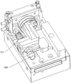
图中的标记:100为工作台,200为料框组件,300为机械手,400为接料口,500为接料滑槽,600为阀体,700为阀盖,1.0为上料站,2.0为压合组装站,3.0为第一移载搬运站,4.0为焊接站,5.0为第二移载搬运站,6.0为打标站,7.0为外泄测试站,8.0为脱附测试站,1.1为上料机,1.10为提升机,1.11为滑道,1.12为振动器,1.13为安装支架,1.14为水平板,1.15为弹性垫块,1.16为位移传感器,2.1为滑台,2.2为阀体工装,2.3为阀盖工装,2.4为驱动电缸,2.5为第一无杆气缸,3.1为工作架,3.2为第一X向导轨,3.3为第一Y向导轨,3.4为第一Z向导轨,3.5为第一X向滑块,3.6为第一Y向滑块,3.7为第一Z向滑块,3.8为第一X向丝杆,3.9为第一Y向丝杆,3.10为第一Z向丝杆,3.11为第一固定架,3.12为第一旋转气缸,3.13为第一气动夹爪,4.1为焊接旋转工装,4.2为激光焊接头,4.3为压紧气缸,4.4为旋转工作台,5.1为台面支架,5.2为直线滑轨,5.3为直线滑块,5.4为移载板,5.5为移载气缸,5.6为第二气动夹爪,5.7为移载驱动气缸,6.1为打标头,6.2为第二无杆气缸,6.3为打标工位,6.4为第二旋转气缸,7.1为旋转气缸转台,7.2为外泄测试工位,7.3为外泄封堵头,7.4为外泄推进气缸,7.5为测漏支架,7.6为测漏仪,7.7为检测气管,8.1为脱附测试工位,8.2为脱附气体通道头,8.3为脱附推进气缸。Marks in the picture: 100 is the worktable, 200 is the material frame assembly, 300 is the manipulator, 400 is the material receiving port, 500 is the material receiving chute, 600 is the valve body, 700 is the valve cover, 1.0 is the feeding station, 2.0 3.0 is the first transfer station, 4.0 is the welding station, 5.0 is the second transfer station, 6.0 is the marking station, 7.0 is the leakage test station, 8.0 is the desorption test station, 1.1 1.10 is the hoist, 1.11 is the slide, 1.12 is the vibrator, 1.13 is the mounting bracket, 1.14 is the horizontal plate, 1.15 is the elastic spacer, 1.16 is the displacement sensor, 2.1 is the sliding table, and 2.2 is the valve body Tooling, 2.3 is the valve cover tooling, 2.4 is the driving electric cylinder, 2.5 is the first rodless cylinder, 3.1 is the work frame, 3.2 is the first X-direction guide, 3.3 is the first Y-direction guide, 3.4 is the first Z-direction guide , 3.5 is the first X-direction slider, 3.6 is the first Y-direction slider, 3.7 is the first Z-direction slider, 3.8 is the first X-direction screw, 3.9 is the first Y-direction screw, 3.10 is the first Z-direction screw, 3.11 is the first fixing frame, 3.12 is the first rotary cylinder, 3.13 is the first pneumatic gripper, 4.1 is the welding rotary tool, 4.2 is the laser welding head, 4.3 is the pressing cylinder, and 4.4 is the rotary table , 5.1 is the table support, 5.2 is the linear slide rail, 5.3 is the linear slider, 5.4 is the transfer plate, 5.5 is the transfer cylinder, 5.6 is the second pneumatic gripper, 5.7 is the transfer drive cylinder, and 6.1 is the marking head , 6.2 is the second rodless cylinder, 6.3 is the marking station, 6.4 is the second rotary cylinder, 7.1 is the rotary cylinder turntable, 7.2 is the leakage test station, 7.3 is the leakage plugging head, and 7.4 is the leakage propulsion Cylinder, 7.5 is the leak detection bracket, 7.6 is the leak detector, 7.7 is the detection gas pipe, 8.1 is the desorption test station, 8.2 is the desorption gas channel head, and 8.3 is the desorption propulsion cylinder.
具体实施方式Detailed ways
结合图1至图19所示的一种文氏管全自动组装线的结构剖视图,在本实施例中,包括工作台100、位于工作台100一侧的上料站1.0以及位于工作台100另一侧的料框组件200;靠近上料站1.0一侧的工作台100上设置有机械手300、压合组装站2.0、第一移载搬运站3.0和焊接站4.0,靠近料框组件200一侧的工作台100上设置有检测站、第二移载搬运站5.0和打标站6.0,且靠近料框组件200一侧的工作台100面上还设有一接料口400,接料口400的底部连接有一朝向料框组件200设置的接料滑槽500;上料站1.0包括两组并排设置的上料机1.1,两组上料机1.1分别用于提升输送文氏管的阀体600和阀盖700;压合组装站2.0包括有滑台2.1以及设置在滑台2.1上的阀体工装2.2、阀盖工装2.3和驱动阀盖工装2.3朝向阀体工装2.2压合的驱动电缸2.4;机械手300设置在上料站1.0和压合组装站2.0之间,且用于将上料机1.1输送的阀体600夹紧送入阀体工装2.2以及将阀盖700夹紧送入阀盖工装2.3,且通过阀体工装2.2和阀盖工装2.3上的压紧旋转电机端部的压紧件压紧阀体和阀盖,进而进行压合组装;焊接站4.0位于滑台2.1远离机械手300的一侧,第一移载搬运站3.0位于压合组装站2.0和焊接站4.0的一侧,且位于远离机械手300的滑台2.1一端,第一移载搬运站将压合组装站2.0上压合组装后的阀体600和阀盖700夹紧送入焊接站4.0,且可将焊接后的阀体600和阀盖700夹紧送入检测站,第二移载搬运站5.0位于检测站的一侧,打标站6.0位于检测站的另一侧,且接料口400位于第二移载搬运站5.0远离检测站的一端。With reference to the structural cross-sectional views of a fully automatic Venturi assembly line shown in FIGS. 1 to 19 , in this embodiment, it includes a
上料机1.1包括有提升机1.10和收集滑道组件,收集滑道组件包括滑道1.11、振动器1.12和弹性垫块1.15,滑道1.11的一端设有位于提升机1.10出料口下方的接料口400,振动器1.12位于滑道1.11的下方,且振动器1.12的固定端通过安装支架1.13连接在提升机1.10的外壳上,且其振动端连接一水平板1.14,且弹性垫块1.15的底端安装在水平板1.14上,且其顶端通过一连接板架支撑在滑道1.11的下方,且滑道1.11的另一端朝向工作台100的上方延伸,且延伸到工作台100上方的滑道1.11端部还设有用于检测工件位置的位移传感器1.16。The feeder 1.1 includes a hoist 1.10 and a collection slideway assembly. The collection slideway assembly includes a slideway 1.11, a vibrator 1.12 and an elastic pad 1.15. One end of the slideway 1.11 is provided with a connection below the discharge port of the elevator 1.10. The
滑台2.1在其下侧的第一无杆气缸2.5的推动下可朝向第一移载搬运站3.0滑动,且第一无杆气缸2.5的滑动块与滑台2.1底侧固定相连,且其固定端固定安装在工作台100上。The sliding table 2.1 can slide toward the first transfer and handling station 3.0 under the push of the first rodless cylinder 2.5 on its lower side, and the sliding block of the first rodless cylinder 2.5 is fixedly connected to the bottom side of the sliding table 2.1, and its fixed The end is fixedly mounted on the table 100 .
第一移载搬运站3.0包括工作架3.1、第一X向导轨3.2、第一Y向导轨3.3、第一Z向导轨3.4、第一X向滑块3.5、第一Y向滑块3.6、第一Z向滑块3.7,第一X向导轨3.2固定在工作架3.1上,且第一X向导轨3.2上架设固定有第一X向丝杆3.8,第一X向丝杆3.8的一端通过第一X向电机驱动旋转,第一X向滑块3.5滑动连接在第一X向导轨3.2上,且套设在第一X向丝杆3.8外,同时与第一X向丝杆3.8通过螺纹连接,第一Y向导轨3.3固定设置在第一X向滑块3.5上,且第一Y向导轨3.3上架设固定有第一Y向丝杆3.9,第一Y向丝杆3.9的一端通过第一Y向电机驱动旋转,第一Y向滑块3.6滑动连接在第一Y向导轨3.3上,且套设在第一Y向丝杆3.9外,同时与第一Y向丝杆3.9通过螺纹连接,第一Z向导轨3.4固定设置在第一Y向滑块3.6上,且第一Z向导轨3.4上架设固定有第一Z向丝杆3.10,第一Z向丝杆3.10的一端通过第一Z向电机驱动旋转,第一Z向滑块3.7滑动连接在第一Z向导轨3.4上,且套设在第一Z向丝杆3.10外,同时与第一Z向丝杆3.10通过螺纹连接,第一Z向滑块3.7上还设有第一固定架3.11,第一固定架3.11的底端连接有第一旋转气缸3.12,且第一旋转气缸3.12的活动端与第一气动夹爪3.13的固定端相连。The first transfer and handling station 3.0 includes a work frame 3.1, a first X-direction guide rail 3.2, a first Y-direction guide rail 3.3, a first Z-direction guide rail 3.4, a first X-direction slider 3.5, a first Y-direction slider 3.6, A Z-direction slider 3.7, the first X-direction guide rail 3.2 is fixed on the work frame 3.1, and a first X-direction screw rod 3.8 is erected and fixed on the first X-direction guide rail 3.2, and one end of the first X-direction screw rod 3.8 passes through the An X-direction motor drives and rotates, and the first X-direction slider 3.5 is slidably connected to the first X-direction guide rail 3.2, and is sleeved outside the first X-direction screw rod 3.8, and is simultaneously connected with the first X-direction screw rod 3.8 by threaded connection , the first Y-direction guide rail 3.3 is fixedly arranged on the first X-direction slider 3.5, and the first Y-direction guide rail 3.3 is erected and fixed with a first Y-direction screw 3.9, one end of the first Y-direction screw 3.9 passes through the first The Y-direction motor is driven to rotate, and the first Y-direction slider 3.6 is slidably connected to the first Y-direction guide rail 3.3, and is sleeved outside the first Y-direction screw 3.9, and is simultaneously connected with the first Y-direction screw 3.9 by threaded connection, The first Z-direction guide rail 3.4 is fixedly arranged on the first Y-direction slider 3.6, and a first Z-direction screw rod 3.10 is erected and fixed on the first Z-direction guide rail 3.4, and one end of the first Z-direction screw rod 3.10 passes through the first Z-direction screw rod 3.10. The first Z-direction slide block 3.7 is slidably connected to the first Z-direction guide rail 3.4, and is sleeved outside the first Z-direction screw rod 3.10, and is simultaneously connected with the first Z-direction screw rod 3.10 through threads. A Z-direction slider 3.7 is also provided with a first fixing frame 3.11, the bottom end of the first fixing frame 3.11 is connected with a first rotating cylinder 3.12, and the movable end of the first rotating cylinder 3.12 is fixed with the first pneumatic clamping jaw 3.13 end connected.
焊接站4.0包括旋转工作台4.4、设置在旋转工作台4.4上的两组焊接旋转工装4.1以及设置在工作台100上且朝向一个焊接旋转工装4.1上工件设置的激光焊接头4.2,焊接旋转工装4.1关于旋转工作台4.4的转动轴对称设置,激光焊接头4.2的一侧还设有一压紧气缸4.3,压紧气缸4.3通过气缸支架固定在工作台100上,压紧气缸4.3的活动端朝向焊接旋转工装4.1上的工件设置,旋转工作台将焊接旋转工装4.1内的文氏管旋转到焊接位后,压紧气缸4.3下压对于文氏管进行定位,进而放松文氏管,且焊接旋转工装在下方连接的旋转电机驱动下实现自转,进而完成文氏管组装位的激光焊接。The welding station 4.0 includes a rotary table 4.4, two sets of welding rotary tooling 4.1 arranged on the rotary table 4.4, and a laser welding head 4.2 arranged on the table 100 and facing the workpiece on one welding rotary tool 4.1, and the welding rotary tool 4.1 Regarding the rotational axis of the rotary table 4.4, a pressing cylinder 4.3 is also provided on one side of the laser welding head 4.2. The pressing cylinder 4.3 is fixed on the table 100 through the cylinder bracket, and the movable end of the pressing cylinder 4.3 rotates toward the welding. The workpiece is set on the tooling 4.1. After the rotary table rotates the venturi in the welding rotary tooling 4.1 to the welding position, the cylinder 4.3 is pressed down to position the venturi, and then the venturi is loosened. Driven by the rotating motor connected below, it realizes self-rotation, and then completes the laser welding of the assembly position of the venturi.
检测站包括外泄测试站7.0和脱附测试站8.0;外泄测试站7.0包括有旋转气缸转台7.1、设置在旋转气缸转台7.1上的两组外泄测试工位7.2、设置在外泄测试工位7.2周边且可与文氏管的管口封堵连接的外泄封堵头7.3以及与外泄封堵头7.3相连的外泄推进气缸7.4,两组外泄测试工位7.2对称设置在旋转气缸转台7.1的转动中心的两侧,且外泄推进气缸7.4可推动外泄封堵头7.3封堵在文氏管的管口,其中一个所述外泄封堵头还可通过一管道与,且两组外泄测试工位7.2之间还设有一测漏支架7.5,测漏支架7.5上安装有测漏仪7.6,测漏仪7.6通过检测气管7.7与其中一个外泄封堵头7.3上设置的进气口相连;文氏管三个管口处的外泄推进气缸7.4分别动作,将文氏管的管口通过外泄封堵头全部密封住,形成完全密封的型腔。此时测漏仪通过检测气管7.7开始向型腔内充气,当气压达到测漏仪预先设定的压力值时,停止充气,并进行保压,同时测漏仪会自动计算充气体积以及充气压力,自动算出一个模拟的标准测试数据,在保压阶段测漏仪会进行泄漏检测。The detection station includes a leakage test station 7.0 and a desorption test station 8.0; the leakage test station 7.0 includes a rotary cylinder turntable 7.1, two sets of leakage test stations 7.2 arranged on the rotary cylinder turntable 7.1, and set on the leakage test station. 7.2 The external leakage plugging head 7.3 that can be connected to the orifice of the venturi tube and the external leakage propulsion cylinder 7.4 connected to the external leakage plugging head 7.3, two sets of external leakage test stations 7.2 are symmetrically arranged on the rotating cylinder On both sides of the rotation center of the turntable 7.1, and the external leakage propulsion cylinder 7.4 can push the external leakage plugging head 7.3 to block the orifice of the venturi, one of the external leakage plugging heads can also pass through a pipeline with, and A leak detection bracket 7.5 is also arranged between the two sets of leakage testing stations 7.2, and a leak detection device 7.6 is installed on the leakage detection bracket 7.5. The air inlets are connected; the leakage at the three orifices of the venturi pushes the cylinders 7.4 to act respectively to seal all the orifices of the venturi through the leakage plugging head to form a completely sealed cavity. At this time, the leak detector starts to inflate the cavity through the detection trachea 7.7. When the air pressure reaches the preset pressure value of the leak detector, the inflation is stopped and the pressure is maintained. At the same time, the leak detector will automatically calculate the inflation volume and inflation pressure. , automatically calculate a simulated standard test data, and the leak detector will perform leak detection during the pressure holding stage.
脱附测试站8.0包括有脱附测试工位8.1、设置在脱附测试工位8.1周边且可与文氏管的管口封堵连接的脱附气体通道头8.2以及与脱附气体通道头8.2相连的脱附推进气缸8.3,且其中一个脱附气体通道头8.2通过连接有调压表、第一流量计的进气管与气源连通,其他需要脱附检测的脱附气体通道头通过出气管与第二流量计连通,当需要进行脱附测试时,文氏管管口处的脱附推进气缸8.3可分别动作,推动脱附气体通道头8.2封堵在管口处,且设定文氏管的进气口,通过进气管通气,且通过检测待检测脱附的管口处的出气量,来实现对于此管口脱附的测试,即,当此管口的出气量达到设定的标准时,此时文氏管组装合格。The desorption test station 8.0 includes a desorption test station 8.1, a desorption gas channel head 8.2 which is arranged around the desorption test station 8.1 and can be connected with the orifice of the venturi and is connected to the desorption gas channel head 8.2 The connected desorption propulsion cylinder 8.3, and one of the desorption gas channel heads 8.2 is connected with the gas source through the intake pipe connected with the pressure regulator and the first flow meter, and the other desorption gas channel heads that require desorption detection pass through the gas outlet pipe. Connected with the second flowmeter, when the desorption test needs to be performed, the desorption propulsion cylinder 8.3 at the mouth of the venturi can be actuated separately to push the desorption gas channel head 8.2 to block the mouth of the tube, and set the venturi The air inlet of the tube is ventilated through the air inlet tube, and the test for the desorption of the nozzle is realized by detecting the air outlet at the nozzle to be detected for desorption, that is, when the air outlet of the nozzle reaches the set value. Standard, the Venturi assembly is qualified at this time.
打标站6.0包括有打标头6.1、第二无杆气缸6.2、打标工位6.3和第二旋转气缸6.4,第二无杆气缸6.2的滑块上设置有气缸支座,第二旋转气缸6.4安装在气缸支座上,且第二旋转气缸6.4的活动端与打标工位6.3相连,第二无杆气缸6.2通过其上配合的滑块带动打标工位6.3在第二移载搬运站5.0下方和打标头6.1下方往返运动。The marking station 6.0 includes a marking head 6.1, a second rodless cylinder 6.2, a marking station 6.3 and a second rotary cylinder 6.4. The slider of the second rodless cylinder 6.2 is provided with a cylinder support, and the second rotary cylinder 6.4 is installed on the cylinder support, and the movable end of the second rotary cylinder 6.4 is connected with the marking station 6.3, and the second rodless cylinder 6.2 drives the marking station 6.3 through the sliding block matched with it to carry it in the second transfer. Reciprocating movement under the station 5.0 and under the marking head 6.1.
第二移载搬运站5.0包括有台面支架5.1、设置在台面支架5.1上的直线滑轨5.2、与直线滑轨5.2配合的直线滑块5.3、设置在直线滑块5.3上的移载板5.4、推动所述移载板沿直线滑轨滑动的移载驱动气缸5.7以及固定在移载板5.4上的三组移载气缸5.5,移载气缸5.5的活动端均连接有第二气动夹爪5.6,且三组第二气动夹爪5.6包括有可在接料口400和打标工位6.3之间往复运动的第一组气动夹爪、可在打标工位6.3和脱附测试工位8.1之间往复运动的第二组气动夹爪以及可在脱附测试工位8.1和靠近脱附测试工位8.1的一个外泄测试工位7.2之间往复运动的第三组气动夹爪。The second transfer and handling station 5.0 includes a table support 5.1, a linear slide rail 5.2 arranged on the table support 5.1, a linear slide block 5.3 matched with the linear slide rail 5.2, a transfer plate 5.4 arranged on the linear slide block 5.3, The transfer driving cylinder 5.7 that pushes the transfer plate to slide along the linear slide rail and the three groups of transfer cylinders 5.5 fixed on the transfer plate 5.4, the movable end of the transfer cylinder 5.5 is connected with a second pneumatic clamping jaw 5.6, And the three sets of second pneumatic grippers 5.6 include a first set of pneumatic grippers that can reciprocate between the
还包括有与上料站1.0、机械手300、压合组装站2.0、第一移载搬运站3.0、焊接站4.0和检测站电连接的控制器。It also includes a controller electrically connected with the loading station 1.0, the
本发明的工作原理是:由于文氏管的阀体600和阀盖700,分别在两组并排设置的上料机1.1的作用下实现的提升上料,且在出料端通过设置一机械手实现阀体和阀盖到压合组装站2.0的过渡,进而控制压合组装站2.0中的阀盖工装2.3朝向阀体工装2.2压合,实现阀盖和阀体的组合,进而滑台朝向第一移载搬运站运动,且在第一移载搬运站的第一气动夹爪3.13的抓取下送入到焊接部进行组装焊接,且在焊接完成后,第一气动夹爪3.13还可将焊接好的文氏管抓取送入到外泄测试站7.0进行外泄测试,外泄测试工位7.2和脱附测试工位8.1用于配合放置待测试的文氏管,且在测试完成后,可通过旋转旋转气缸转台7.1,使得两组外泄测试工位7.2实现180度的旋转,使得焊接好的文氏管处于第三组气动夹爪的下方,通过第三组气动夹爪的抓取送入到脱附测试工位8.1进行脱附测试,进而在第二组气动夹爪的抓取下,送入到打标站打标,进而在第一组气动夹爪的抓取下送入到接料口400,实现文氏管的整个组装焊接测试打标的过程,集成化,且自动化程度较高,较为省时省力。The working principle of the present invention is as follows: due to the
以上所述仅为本发明的优选实施例而已,并不用于限制本发明,尽管参照前述实施例对本发明进行了详细的说明,对于本领域的技术人员来说,其依然可以对前述各实施例所记载的技术方案进行修改,或者对其中部分技术特征进行等同替换。凡在本发明的精神和原则之内,所作的任何修改、等同替换、改进等,均应包含在本发明的保护范围之内。The above descriptions are only preferred embodiments of the present invention, and are not intended to limit the present invention. Although the present invention has been described in detail with reference to the foregoing embodiments, those skilled in the art can still understand the foregoing embodiments. The technical solutions described are modified, or some technical features thereof are equivalently replaced. Any modification, equivalent replacement, improvement, etc. made within the spirit and principle of the present invention shall be included within the protection scope of the present invention.
Claims (9)
Priority Applications (1)
| Application Number | Priority Date | Filing Date | Title |
|---|---|---|---|
| CN201911213511.0A CN110774000B (en) | 2019-12-02 | 2019-12-02 | Venturi tube fully automatic assembly line |
Applications Claiming Priority (1)
| Application Number | Priority Date | Filing Date | Title |
|---|---|---|---|
| CN201911213511.0A CN110774000B (en) | 2019-12-02 | 2019-12-02 | Venturi tube fully automatic assembly line |
Publications (2)
| Publication Number | Publication Date |
|---|---|
| CN110774000A true CN110774000A (en) | 2020-02-11 |
| CN110774000B CN110774000B (en) | 2025-02-14 |
Family
ID=69393487
Family Applications (1)
| Application Number | Title | Priority Date | Filing Date |
|---|---|---|---|
| CN201911213511.0A Active CN110774000B (en) | 2019-12-02 | 2019-12-02 | Venturi tube fully automatic assembly line |
Country Status (1)
| Country | Link |
|---|---|
| CN (1) | CN110774000B (en) |
Cited By (10)
| Publication number | Priority date | Publication date | Assignee | Title |
|---|---|---|---|---|
| CN111780924A (en) * | 2020-06-30 | 2020-10-16 | 昆山科森智能装备有限公司 | High-precision detection system |
| CN111780925A (en) * | 2020-06-30 | 2020-10-16 | 昆山科森智能装备有限公司 | Automatic detection system for precision part |
| CN112427829A (en) * | 2020-11-16 | 2021-03-02 | 保隆(安徽)汽车配件有限公司 | Automatic assembling system and method for tubular outer liner and supporting sheet |
| CN112649163A (en) * | 2020-12-17 | 2021-04-13 | 云智动(杭州)科技有限公司 | Production line of occult blood self-testing tube |
| CN113246069A (en) * | 2021-06-18 | 2021-08-13 | 爱普科学仪器(江苏)有限公司 | Automatic assembling machine for medicine bag |
| CN113427259A (en) * | 2021-07-16 | 2021-09-24 | 常州市龙星工业自动化系统有限公司 | Automatic production line for lithium battery packs |
| CN113634910A (en) * | 2021-10-13 | 2021-11-12 | 如皋臣杰精密机械有限公司 | Workpiece conveying and processing system |
| CN114212500A (en) * | 2020-05-27 | 2022-03-22 | 广东原点智能技术有限公司 | Warehouse entry handling device |
| CN114535803A (en) * | 2022-04-26 | 2022-05-27 | 广东国玉科技有限公司 | Intelligent laser welding equipment |
| CN119802272A (en) * | 2025-03-12 | 2025-04-11 | 福州景腾精工橡塑制品有限公司 | Vacuum pressure maintaining valve and production process thereof |
Citations (6)
| Publication number | Priority date | Publication date | Assignee | Title |
|---|---|---|---|---|
| JPH081460A (en) * | 1994-06-22 | 1996-01-09 | Jatco Corp | Tube connector assembly device |
| JP2010142911A (en) * | 2008-12-19 | 2010-07-01 | Honda Motor Co Ltd | Work positioning system and work positioning method |
| CN103084830A (en) * | 2013-01-16 | 2013-05-08 | 大连理工大学 | A non-gap plastic attachment precision assembly equipment for the stator shielding sleeve of the nuclear main pump |
| CN103143930A (en) * | 2013-01-28 | 2013-06-12 | 厦门精奥自动化科技有限公司 | Automatic assembly equipment for carbureter |
| CN109175953A (en) * | 2018-09-04 | 2019-01-11 | 昆山迈思特自动化科技有限公司 | A kind of compo pipe button that is loaded surveys water-tight equipment |
| CN211162814U (en) * | 2019-12-02 | 2020-08-04 | 苏州迅益科系统科技有限公司 | Full-automatic venturi assembly line |
-
2019
- 2019-12-02 CN CN201911213511.0A patent/CN110774000B/en active Active
Patent Citations (6)
| Publication number | Priority date | Publication date | Assignee | Title |
|---|---|---|---|---|
| JPH081460A (en) * | 1994-06-22 | 1996-01-09 | Jatco Corp | Tube connector assembly device |
| JP2010142911A (en) * | 2008-12-19 | 2010-07-01 | Honda Motor Co Ltd | Work positioning system and work positioning method |
| CN103084830A (en) * | 2013-01-16 | 2013-05-08 | 大连理工大学 | A non-gap plastic attachment precision assembly equipment for the stator shielding sleeve of the nuclear main pump |
| CN103143930A (en) * | 2013-01-28 | 2013-06-12 | 厦门精奥自动化科技有限公司 | Automatic assembly equipment for carbureter |
| CN109175953A (en) * | 2018-09-04 | 2019-01-11 | 昆山迈思特自动化科技有限公司 | A kind of compo pipe button that is loaded surveys water-tight equipment |
| CN211162814U (en) * | 2019-12-02 | 2020-08-04 | 苏州迅益科系统科技有限公司 | Full-automatic venturi assembly line |
Cited By (13)
| Publication number | Priority date | Publication date | Assignee | Title |
|---|---|---|---|---|
| CN114212500A (en) * | 2020-05-27 | 2022-03-22 | 广东原点智能技术有限公司 | Warehouse entry handling device |
| CN114212500B (en) * | 2020-05-27 | 2024-02-02 | 广东原点智能技术有限公司 | Warehouse entry handling device |
| CN111780925A (en) * | 2020-06-30 | 2020-10-16 | 昆山科森智能装备有限公司 | Automatic detection system for precision part |
| CN111780924A (en) * | 2020-06-30 | 2020-10-16 | 昆山科森智能装备有限公司 | High-precision detection system |
| CN112427829A (en) * | 2020-11-16 | 2021-03-02 | 保隆(安徽)汽车配件有限公司 | Automatic assembling system and method for tubular outer liner and supporting sheet |
| CN112649163A (en) * | 2020-12-17 | 2021-04-13 | 云智动(杭州)科技有限公司 | Production line of occult blood self-testing tube |
| CN113246069A (en) * | 2021-06-18 | 2021-08-13 | 爱普科学仪器(江苏)有限公司 | Automatic assembling machine for medicine bag |
| CN113246069B (en) * | 2021-06-18 | 2021-09-17 | 爱普科学仪器(江苏)有限公司 | Automatic assembling machine for medicine bag |
| CN113427259A (en) * | 2021-07-16 | 2021-09-24 | 常州市龙星工业自动化系统有限公司 | Automatic production line for lithium battery packs |
| CN113634910A (en) * | 2021-10-13 | 2021-11-12 | 如皋臣杰精密机械有限公司 | Workpiece conveying and processing system |
| CN114535803A (en) * | 2022-04-26 | 2022-05-27 | 广东国玉科技有限公司 | Intelligent laser welding equipment |
| CN114535803B (en) * | 2022-04-26 | 2022-07-01 | 广东国玉科技有限公司 | Intelligent laser welding equipment |
| CN119802272A (en) * | 2025-03-12 | 2025-04-11 | 福州景腾精工橡塑制品有限公司 | Vacuum pressure maintaining valve and production process thereof |
Also Published As
| Publication number | Publication date |
|---|---|
| CN110774000B (en) | 2025-02-14 |
Similar Documents
| Publication | Publication Date | Title |
|---|---|---|
| CN110774000A (en) | Automatic Venturi Assembly Line | |
| CN109352335B (en) | Throttle valve assembly line | |
| CN106622989B (en) | An automated retrieving and sorting mechanism | |
| CN102874439B (en) | Flatness detecting and packaging device | |
| CN106041375A (en) | Battery cap welding machine | |
| CN211763566U (en) | Full-automatic ultrasonic welding system for filter | |
| CN109822347B (en) | Vacuum bottle assembling machine and oiling process thereof | |
| CN205404048U (en) | Airtightness detecting device | |
| CN213748923U (en) | Air tightness detection device | |
| CN211160749U (en) | CVJ inner sphere diameter diagonal diameter detector | |
| CN117733510A (en) | Automatic press fitting equipment and press sleeve process thereof | |
| CN108857330A (en) | A kind of wheel hub valve port automatic stopper device | |
| CN107470899B (en) | Right end assembly machine of automatic assembly line of fuel pump and operation method of right end assembly machine | |
| CN207447830U (en) | Noise reduction bag is airtight to detect automatic screw nailing equipment of carving characters | |
| CN116735618A (en) | Intelligent detection equipment for square joint of automobile | |
| CN111203634A (en) | A double-station mobile phone middle plate nut welding machine | |
| CN209239283U (en) | A double-station mobile phone middle plate nut welding machine | |
| CN111438500A (en) | Automatic assembling and detecting equipment for condenser | |
| CN211687294U (en) | Double-station air tightness detection device | |
| CN111633670A (en) | Sorting manipulator for linear output of formed mechanical parts | |
| CN215477968U (en) | Electricity core production line | |
| CN211162814U (en) | Full-automatic venturi assembly line | |
| CN113058883B (en) | A multi-station integrated linkage automatic inspection mechanism | |
| CN205333574U (en) | Multistation ultrasonic testing device | |
| CN118527972A (en) | Oiling stop valve assembly quality |
Legal Events
| Date | Code | Title | Description |
|---|---|---|---|
| PB01 | Publication | ||
| PB01 | Publication | ||
| SE01 | Entry into force of request for substantive examination | ||
| SE01 | Entry into force of request for substantive examination | ||
| GR01 | Patent grant | ||
| GR01 | Patent grant | ||
| TR01 | Transfer of patent right | ||
| TR01 | Transfer of patent right |
Effective date of registration: 20250410 Address after: No. 425 Chaoyang Road, Shuangliu District, Chengdu, Sichuan Province, 610000 Patentee after: Li Zhengmao Country or region after: China Address before: 11th Floor, Kangyang Building, No. 406 Chunfeng Road, Huangdai Town, Xiangcheng District, Suzhou City, Jiangsu Province, 215000 Patentee before: Suzhou xunyiko System Technology Co.,Ltd. Country or region before: China |