CN110768812B - Server management system and method - Google Patents
Server management system and method Download PDFInfo
- Publication number
- CN110768812B CN110768812B CN201810830402.2A CN201810830402A CN110768812B CN 110768812 B CN110768812 B CN 110768812B CN 201810830402 A CN201810830402 A CN 201810830402A CN 110768812 B CN110768812 B CN 110768812B
- Authority
- CN
- China
- Prior art keywords
- node
- server
- management instruction
- management
- forwarding
- Prior art date
- Legal status (The legal status is an assumption and is not a legal conclusion. Google has not performed a legal analysis and makes no representation as to the accuracy of the status listed.)
- Active
Links
- 238000000034 method Methods 0.000 title description 15
- 238000007726 management method Methods 0.000 claims abstract description 139
- 238000012360 testing method Methods 0.000 claims description 9
- 238000004891 communication Methods 0.000 claims description 8
- 230000000694 effects Effects 0.000 claims description 5
- 230000000977 initiatory effect Effects 0.000 claims 2
- 238000012163 sequencing technique Methods 0.000 claims 2
- 230000005540 biological transmission Effects 0.000 description 17
- 230000008569 process Effects 0.000 description 5
- 238000010586 diagram Methods 0.000 description 3
- 238000005516 engineering process Methods 0.000 description 3
- 230000002159 abnormal effect Effects 0.000 description 2
- 230000006870 function Effects 0.000 description 2
- 238000012986 modification Methods 0.000 description 2
- 230000004048 modification Effects 0.000 description 2
- 238000012545 processing Methods 0.000 description 2
- 238000013459 approach Methods 0.000 description 1
- 238000004590 computer program Methods 0.000 description 1
- 238000013480 data collection Methods 0.000 description 1
- 238000011161 development Methods 0.000 description 1
- 238000009434 installation Methods 0.000 description 1
- 238000012423 maintenance Methods 0.000 description 1
- 230000003287 optical effect Effects 0.000 description 1
- 238000011084 recovery Methods 0.000 description 1
- 238000011160 research Methods 0.000 description 1
- 238000006467 substitution reaction Methods 0.000 description 1
- 230000001052 transient effect Effects 0.000 description 1
- 230000007723 transport mechanism Effects 0.000 description 1
Images


Classifications
-
- H—ELECTRICITY
- H04—ELECTRIC COMMUNICATION TECHNIQUE
- H04L—TRANSMISSION OF DIGITAL INFORMATION, e.g. TELEGRAPHIC COMMUNICATION
- H04L41/00—Arrangements for maintenance, administration or management of data switching networks, e.g. of packet switching networks
- H04L41/04—Network management architectures or arrangements
-
- H—ELECTRICITY
- H04—ELECTRIC COMMUNICATION TECHNIQUE
- H04L—TRANSMISSION OF DIGITAL INFORMATION, e.g. TELEGRAPHIC COMMUNICATION
- H04L41/00—Arrangements for maintenance, administration or management of data switching networks, e.g. of packet switching networks
- H04L41/08—Configuration management of networks or network elements
- H04L41/0803—Configuration setting
Landscapes
- Engineering & Computer Science (AREA)
- Computer Networks & Wireless Communication (AREA)
- Signal Processing (AREA)
- Computer And Data Communications (AREA)
Abstract
The invention discloses a server management system and a server management method. The disclosed system comprises: the central node is used for issuing a management instruction and receiving an execution result; the first server node is used for receiving the forwarded first management instruction, executing the first management instruction, returning a first execution result of the first management instruction, receiving the forwarded second management instruction, forwarding the second management instruction, receiving a second execution result of the second management instruction and forwarding the second execution result; and a second server node, configured to receive a second management instruction forwarded by the first server node, execute the second management instruction, and return a second execution result to the first server node, where one first server node is determined as a forwarding node from at least two first server nodes having a capability of forwarding the second management instruction and the second execution result. The disclosed scheme can configure a plurality of paths to reach the same managed node, and the optimal path is selected when the scheme is executed.
Description
Technical Field
The invention relates to the technical field of computer networks, in particular to a server management system and a server management method.
Background
With the continuous expansion of computer networks, tens of thousands or even hundreds of thousands of servers may exist in a network at the same time. How to efficiently manage these mass servers, such as executing instructions in batches, making configuration changes, and obtaining instruction execution results, has been a focus of research.
In the prior art, management of a mass server is generally realized by performing secondary development by using open-source automated operation and maintenance software (or called server centralized management software) such as saltstack, ansable and the like, or by using proxy software such as haproxy, nginx and the like. In the case of a small number of servers in the network (e.g., several hundred to several thousand), this approach can basically satisfy the requirement of managing the servers.
However, when the number of servers is huge (tens of thousands or even hundreds of thousands), the network condition is complex, and the concurrent use is high in frequency, the requirement for effective management of massive servers cannot be met by using these open source software.
The following takes the prior art scheme using saltstack for server management as an example to illustrate the major drawbacks of the prior art scheme.
Fig. 1 shows a schematic diagram of a prior art solution for server management using saltstack. As shown in fig. 1, the technical solution employs 3 layers of nodes, the first layer is a master (i.e., a central node), the second layer is a syntic (i.e., a proxy node), and the third layer is an Minion (i.e., a managed server node). The central node indirectly manages the server nodes through the proxy nodes. This solution mainly has the following drawbacks:
(1) Cannot cope with complicated network environments and changes.
For example, since the network between the central node and other managed machines is not always connected, a proxy node needs to be introduced, saltstack uses the syncic as the proxy node to forward information, and when the proxy node fails or the network becomes poor, adding and changing the proxy node needs complex operations (for example, including specific steps of selecting a machine, installing software, modifying configuration, and the like); moreover, the final quality of information forwarding cannot be judged in advance before the standby machine is selected, and whether the selected standby machine is suitable for being used as the proxy node or not can be known only after the standby machine is operated, and if the standby machine is not suitable for being used as the proxy node, the standby machine needs to be reselected.
(2) Multiple tasks cannot be run simultaneously.
For example, when tens of thousands of machines are managed simultaneously, all resources of the central node are exhausted, the success rate is low, and the memory may be exhausted due to the recovery of the result. The situation is more serious in the case that a plurality of tasks are executed simultaneously, and the number of the single-machine sockets is not enough to be distributed.
(3) The real-time performance is poor.
For example, due to the limitations of the programming language (e.g., interpreted python language is used, the operation efficiency is low) and the concurrency model (processes or threads, the creation and switching costs are high) adopted in the prior art, tens of minutes of execution time is generally required when ten thousands of machines execute the management instructions simultaneously, and there may be some machines losing feedback data, resulting in inaccurate data collection results. The method cannot be applied to scenes with high requirements on real-time performance and reliability.
(4) The installation management of agent software such as saltstack is inconvenient.
(5) Abnormal status of the agent software used on the agent node (e.g., agent software hanging down) may affect the functionality of the agent node itself.
(6) The proxy software needs to occupy an additional port, and the scenario that the server has a limited open port can be influenced.
(7) The agent software needs configuration and safety control, and the adding and deleting machines need to modify the configuration, so that the maintenance cost is high.
(8) Existing proxy software such as haproxy and nginx do not support forwarding of the HTTP2.0 protocol of the seventh layer, are not suitable for maintaining long connections, and have no way to multiplex connections. Due to the limitation of the old HTTP 1.X protocol supported, all data must be transmitted in time sequence by multiplexing the same connection, so that the receiver cannot distinguish between data arriving at the same time.
In order to solve the above problems, a new technical solution needs to be proposed.
Disclosure of Invention
The server management system according to the present invention includes:
the central node is used for issuing management instructions for managing different server nodes and receiving execution results of the management instructions;
the first server node is used for receiving a first management instruction forwarded by the central node or other first service nodes, executing the first management instruction, returning a first execution result of the first management instruction to the central node or other first service nodes, receiving a second management instruction forwarded by the central node or other first service nodes, forwarding the second management instruction, receiving a second execution result of the second management instruction, and forwarding the second execution result to the central node or other first service nodes; and
a second server node, the second server node is used for receiving the second management instruction forwarded by the first server node, executing the second management instruction and returning a second execution result to the first server node,
wherein one first server node is determined as a forwarding node from among at least two first server nodes having a capability of forwarding the second management instruction and the second execution result.
According to the server management system of the present invention, the second server node is further configured to:
receiving a second management instruction from the central node, forwarding the second management instruction to other second server nodes, receiving a third execution result of the second management instruction from other second server nodes, forwarding the third execution result to the central node or the first server node,
wherein the first server node is further configured to: and forwarding the third execution result to the central node or other first service nodes.
According to the server management system of the present invention, the communication among the center node, the first server node, and the second server node is based on the long connection mode of HTTP 2.0.
According to the server management system, different management instructions between the central node, the first server node and the second server node on the same long connection based on HTTP2.0 are distinguished based on different data streams and/or different data frames.
According to the server management system of the present invention, the central node is further configured to:
it is determined whether the first server node and the second server node act as forwarding nodes.
The server management method comprises the following steps:
the central node performs the following steps:
issuing management instructions for managing different server nodes,
receiving an execution result of the management instruction;
the first server node performs the steps of:
receiving a first management instruction forwarded by the central node or other first service nodes, executing the first management instruction, returning a first execution result of the first management instruction to the central node or other first service nodes,
receiving a second management instruction forwarded by the central node or other first service nodes, forwarding the second management instruction,
receiving a second execution result of the second management instruction, and forwarding the second execution result to the central node or other first service nodes; and
the second server node performs the steps of:
and receiving a second management instruction forwarded by the first server node, executing the second management instruction, and returning a second execution result to the first server node.
According to the server management method of the present invention, the central node further performs the steps of:
one first server node is determined as a forwarding node from among at least two first server nodes having the capability of forwarding the second management instruction and the second execution result.
According to the server management method of the present invention, the second server node further performs the steps of:
receiving a second management instruction from the central node, forwarding the second management instruction to other second server nodes, receiving a third execution result of the second management instruction from other second server nodes, and forwarding the third execution result to the central node or the first server node;
the first server node further performs the steps of:
and forwarding the third execution result to the central node or other first service nodes.
According to the server management method of the present invention, the communication among the center node, the first server node, and the second server node is based on the long connection mode of HTTP 2.0.
According to the server management method, different management instructions between the central node, the first server node and the second server node on the same long connection based on HTTP2.0 are distinguished based on different data streams and/or different data frames.
According to the technical scheme of the invention, a plurality of paths can be configured to reach the same managed node, and the optimal path is selected during execution.
Drawings
The accompanying drawings, which are incorporated in and constitute a part of the specification, illustrate embodiments of the invention and together with the description, serve to explain the principles of the invention. In the drawings, like reference numerals are used to indicate like elements. The drawings in the following description are illustrative of some, but not all embodiments of the invention. To a person skilled in the art, without inventive effort, other figures can be derived from these figures.
Fig. 1 shows a schematic diagram of a prior art solution for server management using saltstack.
Fig. 2 shows a schematic diagram of a server management system according to the invention.
Fig. 3 (a) -3 (c) schematically show a schematic flow chart of a server management method according to the present invention.
Detailed Description
In order to make the objects, technical solutions and advantages of the embodiments of the present invention clearer, the technical solutions in the embodiments of the present invention will be clearly and completely described below with reference to the drawings in the embodiments of the present invention, and it is obvious that the described embodiments are some, but not all, embodiments of the present invention. All other embodiments, which can be obtained by a person skilled in the art without making any creative effort based on the embodiments in the present invention, belong to the protection scope of the present invention. It should be noted that the embodiments and features of the embodiments in the present application may be arbitrarily combined with each other without conflict.
Fig. 2 shows schematically a server management system according to the invention.
As shown in fig. 2, the server management system according to the present invention includes:
the central node (i.e., a server (master) in fig. 2) is configured to issue a management instruction for managing different server nodes, and receive an execution result of the management instruction;
the first server node (i.e., agent-a (forwarding), agent-b (forwarding), and agent-f (forwarding) in fig. 2) is configured to receive a first management instruction forwarded from the central node or another first service node, execute the first management instruction, return a first execution result of the first management instruction to the central node or another first service node, receive a second management instruction forwarded from the central node or another first service node, forward the second management instruction, receive a second execution result of the second management instruction, and forward the second execution result to the central node or another first service node; and
the second server nodes (i.e. agent-c, agent-d, agent-e, agent-h in fig. 2) are configured to receive the second management instruction forwarded by the first server node, execute the second management instruction, return a second execution result to the first server node,
wherein one first server node is determined as a forwarding node (i.e., "there are multiple paths to the same agent" in fig. 2) from among at least two first server nodes having the capability of forwarding the second management instruction and the second execution result.
Optionally, the second server node (i.e., agent-g in fig. 2) is further configured to:
receiving a second management instruction from the central node, forwarding the second management instruction to other second server nodes, receiving a third execution result of the second management instruction from other second server nodes, forwarding the third execution result to the central node or the first server node,
wherein the first server node is further configured to:
and forwarding the third execution result to the central node or other first service nodes.
Optionally, the communication between the central node, the first server node, and the second server node is based on the long connection mode of HTTP2.0 (i.e., "long connection" in fig. 2).
Optionally, different management instructions between the central node, the first server node, and the second server node on the same long HTTP2.0 based connection are distinguished based on different data streams and/or different data frames.
Optionally, the central node is further configured to:
it is determined whether the first server node and the second server node act as forwarding nodes (i.e., "central policy decision direct connection or forwarding" in fig. 2).
For example, a server node (i.e., the above-described central node) may install a server (server) module, and a plurality of agent nodes (including a first server node and a second server node) may install a client (agent) module.
The server node may be configured to: the method comprises the steps of (1) receiving an instruction (such as a management instruction) task, (2) managing a transmission mode of a scheduling instruction, (3) collecting an execution result of an agent, (4) providing an interface for submitting a query task state.
The agent node can be used to: (1) Receiving the instruction execution of the local machine and returning a result (2) receiving the forwarding instruction and sending the forwarding instruction to the target machine and collecting the result.
For example, HTTP2.0 connections can be established between the server node and the agent node, and between the agent node and the agent node, and the connections are maintained (long connections) and heartbeats are maintained, on which different task instructions can be executed in parallel, using the property of HTTP2.0 multiplexing.
For example, TLS encryption using HTTP2.0 may also be used to ensure reliability and security of data transmission.
For example, the server module in the server node and the client module in the agent node can be developed by using a go language. Compared with the prior art scheme of the saltstack technology developed based on the python language, the processing time delay is reduced, and the real-time performance is improved.
For example, coroutines may be used as a concurrency model in place of prior art processes and/or threads. Compared with the prior art scheme using processes and/or threads, the method and the device can enable a common server to simultaneously run hundreds of thousands of coroutines to perform concurrent instruction issuing operation, further reduce processing time delay and further improve instantaneity.
For example, data transmission may also be performed in units of binary data frames and/or data streams based on the HTTP2.0 protocol, i.e., data may be identified (i.e., multiplexed) based on the data frames and/or data streams.
For example, different instructions may be issued simultaneously on the same HTTP2.0 long connection, and different instructions (e.g., management instructions) and their respective execution results may be distinguished by data frames and/or data streams.
For example, fig. 2 shows several cases of data (including the above management instructions) transmission in a complex network:
1. agent-a, agent-b and agent-g represent nodes directly communicated with the server node, and direct data transmission can be carried out among the agent-a, the agent-b, the agent-g and the server node.
2. agent-c, agent-d, agent-e, and agent-f represent nodes that cannot be directly connected to the server node, but are directly connected to agent-a or agent-b, and the tasks of agent-c, agent-d, agent-e, and agent-f (i.e., the instructions for managing them) can be forwarded through agent-a or agent-b. That is, agent-c, agent-d, agent-e, agent-f and server nodes can perform indirect data transmission through the primary forwarding of agent-a or agent-b.
3. agent-h represents a node which cannot be directly communicated with the server node, agent-a and agent-b and is directly communicated with agent-f, and the task of agent-h (i.e. the instruction for managing the task) needs to be forwarded through agent-b and then through agent-f. That is, the agent-h and the server node can perform indirect data transmission through the two-time forwarding of the agent-b and the agent-f.
Compared with the prior art (for example, a scheme of using saltstack, ansable, hash, nginx, and the like to manage the server) the technical scheme of the invention has the following advantages:
1. in the prior art, for example, when a problem occurs in an agent-b node, a task of an agent-d cannot be executed, and the task fails. This is because there is a one-to-many relationship between the agent node (e.g., agent-b node) and the managed node (e.g., agent-d node) in the prior art. When a problem occurs in a proxy node, if the proxy node is not picked again and reconfigured, the tasks that the machine (i.e., managed node) of the proxy node responsible for the proxy needs to perform fail.
However, the proxy node and the managed node in the above technical solution according to the present invention are many-to-many relationship. If the agent-b node has problems and the server node is about to issue instructions to the agent-d node, the strategy of the server node is to try forwarding by the agent-b node first, try forwarding by the agent-a node when the connection state between the server node and the agent-b node is found to be abnormal, and normally execute forwarding through the agent-a node if the connection state between the server node and the agent-a node is detected to be normal, so that the task is successfully forwarded to the agent-d node.
2. In the prior art, for example, when the agent-a node has a problem, the task of the agent-c node cannot be executed, which results in a task failure. Therefore, the proxy node needs to be replaced at this time. If the agent-g node is set as a new agent node to issue an instruction to the agent-c node, the agent software in the prior art needs to be installed on the agent-g node (machine), and the agent-g node is configured, so that the agent-g node performs data forwarding operation on the agent-c node. Moreover, after the agent software is installed, the connectivity between the agent-g node and the master node and between the agent-c node also need to be tested, and if the finally obtained test result shows that the nodes are not connected or have poor connectivity, the above operation steps need to be repeated until a proper agent node is manually selected, which is long in time consumption and high in labor cost.
However, according to the above technical solution of the present invention, since each node can forward, the master node can scan the machines (nodes) regularly (automatically), and it is ensured that each machine has more than two or three machines connected to it, when the agent-a node has a problem, since it is predicted in advance that the agent-g node is connected to the agent-c node, the policy can be directly and automatically modified to make the task of the agent-c node forwarded by the agent-g node (as shown by the dotted arrow in fig. 2).
It may be arranged that a test request is initiated to all machines at a fixed time interval (e.g. 5 minutes), the test request including the test path, the test machine, the data transmission time, and the duration of the test path. The shorter the data transmission time and the longer the path continuous use time, the better the forwarding effect, and the forwarding machine on the path can be preferentially used for data forwarding. Taking a single machine as an example, the inverse value of data transmission time from other nodes to the machine and the path connection duration value are subjected to weighted summation, and the final summation result is sorted according to the value size, so that the sorting result corresponding to the sequence of good forwarding effect to bad forwarding effect can be obtained, and when the optimal path can be obtained by selecting the nodes according to the sorting result.
3. In the prior art, for example, when instructions need to be issued to ten thousand machines and a plurality of instruction tasks need to be issued simultaneously, the operation cannot be completed by using a saltstack; when the scheme based on haproxy, nginx and HTTP 1.X protocols is used for forwarding the instructions, connection needs to be reestablished every time, the number of the connections needed to be established by the master node is the number of machines multiplied by the number of instruction tasks, and at the moment, the number of sockets of the machines can be consumed rapidly, so that the services are unavailable. It takes a cost to establish a connection. Moreover, since the link state of the network is not known, a connection timeout threshold is usually set, and when the connection timeout threshold is not exceeded, other tasks are blocked, resulting in poor real-time performance. The concurrent model uses processes, which causes high overhead of scheduling among the processes and can not run too many instructions simultaneously.
However, according to the technical scheme of the invention, the used data transmission channels are all in HTTP2.0 long connection, if ten thousand machines are hung under the agent-a node, the central node sends out ten thousand connections with the same HTTP2.0 long connection between the multiplexing central node and the agent-a node, the central node only needs to establish the HTTP2.0 long connections between the central node and the forwarding node and between the central node and the direct connection node, and different tasks can multiplex the same HTTP2.0 long connection. Furthermore, the master (i.e., the central node) maintains the state of the HTTP2.0 long connection, determines the connection state directly when the connection is to be used, and does not need to wait for a connection to be established when an instruction is to be issued. For example, a dynamic policy may be configured in the central node to specify the transmission method of the instruction, and the proxy node and the transmission path may be changed by changing the dynamic policy. Multiple paths to the same machine can be configured, and the optimal path is selected when data transmission is performed.
Fig. 3 (a) -3 (c) exemplarily show schematic flowcharts of a server management method according to the present invention.
The server management method comprises the following steps:
as shown in the solid line box of fig. 3 (a), the central node performs the following steps:
step C302: issuing a management instruction for managing different server nodes,
step C304: receiving an execution result of the management instruction;
as shown in the solid line box of fig. 3 (b), the first server node performs the following steps:
step F302: receiving a first management instruction forwarded by the central node or other first service nodes, executing the first management instruction, returning a first execution result of the first management instruction to the central node or other first service nodes,
step F304: receiving a second management instruction forwarded by the central node or other first service nodes, forwarding the second management instruction,
step F306: receiving a second execution result of the second management instruction, and forwarding the second execution result to the central node or other first service nodes; and
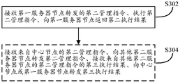
as shown in the solid line box of fig. 3 (c), the second server node performs the following steps:
step S302: and receiving a second management instruction forwarded by the first server node, executing the second management instruction, and returning a second execution result to the first server node.
Optionally, as shown by the dashed box in fig. 3 (a), the central node further performs the following steps:
step C306: one first server node is determined as a forwarding node from among at least two first server nodes having the capability of forwarding the second management instruction and the second execution result.
Optionally, as shown by the dashed box in fig. 3 (c), the second server node further performs the following steps:
step S304: receiving a second management instruction from the central node, forwarding the second management instruction to other second server nodes, receiving a third execution result of the second management instruction from other second server nodes, and forwarding the third execution result to the central node or the first server node;
as shown in the dashed box of fig. 3 (b), the first server node further performs the following steps:
step F308: and forwarding the third execution result to the central node or other first service nodes.
Optionally, the communication between the central node, the first server node, and the second server node is based on a long connection mode of HTTP 2.0.
Optionally, different management instructions between the central node, the first server node, and the second server node on the same long HTTP2.0 based connection are distinguished based on different data streams and/or different data frames.
Optionally, as shown by the dashed box in fig. 3 (a), the central node further performs the following steps:
step C308: it is determined whether the first server node and the second server node act as forwarding nodes.
In order to make the above-mentioned server management method according to the present invention more clear to those skilled in the art, the following description will be made in conjunction with a specific embodiment. This embodiment may include the steps of:
1. the agent node implements an rpc (remote procedure call, which is a request for service from a remote computer program over a network) of instruction calls for accepting and executing instructions from the central node or forwarding node.
2. and the agent node uses a custom protocol to realize the rpc of the forwarding instruction.
For example, the following exemplary custom protocols may be used:
a) If an instruction is directly issued to the agent-g node in the graph, the instruction is directly issued to the agent-g node in a form of (agent-g + instruction content), and a result is returned.
b) If an instruction is sent to the agent-h node in the graph, the generated (agent-b-agent-f-agent-h + instruction content) is sent to an agent-b machine (node), if the instruction is received by the agent-b machine and found to be a forwarding instruction, the generated (agent-f-agent-h + instruction content) is sent to an agent-f machine, and the agent-f machine sends the generated (agent-h + instruction content) to the agent-h machine, and then the result is returned in sequence.
3. A long connection pool of HTTP2.0 is implemented.
a) To facilitate the determination of the state, the state of the HTTP2.0 connection includes: "ready: normal use "," idle: in-connection or transient failure "," shutdown: three types of connections are broken or closed ".
b) Caching each used HTTP2.0 connection in a memory.
c) An independent thread is started, and the connection state of each HTTP2.0 is scanned in real time by using the lru strategy. If it is ready, it is used directly; if idle, mark the connection as failed, but not delete the connection; if the state is recovered to ready within the set timeout, the connection is marked as normal; if the timeout time is reached or the connection is actively closed, the connection is marked as shutdown, and the connection is rejected.
4. When the rpc of the agent node is called, whether the required connection exists or not is inquired from a local connection pool, if not, the connection is established, and the heartbeat is kept for modifying the connection state; if yes, the connection state is judged, and if the connection state is normal (ready), the connection state is directly used.
5. The server node uses the forwarding rpc of the agent node to perform scanning test on all managed machines (nodes), detects the connectivity among the machines, and generates a strategy for issuing the instruction for use in issuing.
6. And the server node scans the agent node at regular time and adjusts the strategy.
7. The server node provides a packaged interface, an external part can submit an instruction issuing task and appoint a machine list, a concurrency number, timeout time and the like to the server node, and the server node issues instructions to each target machine according to a strategy and collects results.
8. The server node provides an interface for task state query to query the task state.
According to the technical scheme of the invention, the method has the following advantages:
1. multiple paths can be configured to reach the same managed node, and the optimal path is selected when the optimal path is selected.
2. All nodes except the central node can be used as forwarding nodes, and the addition and modification of the proxy nodes are quick.
3. A general strategy can be configured at the central node to formulate a command transmission mode, and the proxy node and the transmission path can be changed by modifying the strategy.
4. The long connection can be kept between the server node and the agent node or between the agent node and the agent node, and the cost for establishing the connection is not spent. Different instructions can multiplex long connection, performance is improved, and a large amount of instruction transmission can be executed by using a small amount of sockets. The heartbeat can be kept, and the strategy can be adjusted in time when the network shakes or the agent node fails.
5. The issuing, executing and execution result receiving operations for hundreds of thousands of instructions can be executed in parallel, and the delay of the operations is far less than that of the prior art and is almost real-time.
The above-described embodiments can be implemented individually or in various combinations, and such variations are within the scope of the present invention.
It will be understood by those of ordinary skill in the art that all or some of the steps of the methods, systems, functional modules/units in the devices disclosed above may be implemented as software, firmware, hardware, and suitable combinations thereof. In a hardware implementation, the division between functional modules/units mentioned in the above description does not necessarily correspond to the division of physical components; for example, one physical component may have multiple functions, or one function or step may be performed by several physical components in cooperation. Some or all of the components may be implemented as software executed by a processor, such as a digital signal processor or microprocessor, or as hardware, or as an integrated circuit, such as an application specific integrated circuit. Such software may be distributed on computer readable media, which may include computer storage media (or non-transitory media) and communication media (or transitory media). The term computer storage media includes volatile and nonvolatile, removable and non-removable media implemented in any method or technology for storage of information such as computer readable instructions, data structures, program modules or other data, as is well known to those skilled in the art. Computer storage media includes, but is not limited to, RAM, ROM, EEPROM, flash memory or other memory technology, CD-ROM, digital Versatile Disks (DVD) or other optical disk storage, magnetic cassettes, magnetic tape, magnetic disk storage or other magnetic storage devices, or any other medium which can be used to store the desired information and which can accessed by a computer. In addition, communication media typically embodies computer readable instructions, data structures, program modules or other data in a modulated data signal such as a carrier wave or other transport mechanism and includes any information delivery media as known to those skilled in the art.
Finally, it should be noted that: the above examples are only intended to illustrate the technical solution of the present invention, and not to limit it. Although the present invention has been described in detail with reference to the foregoing embodiments, it will be understood by those of ordinary skill in the art that: the technical solutions described in the foregoing embodiments may still be modified, or some technical features may be equivalently replaced; and such modifications or substitutions do not depart from the spirit and scope of the corresponding technical solutions of the embodiments of the present invention.
Claims (9)
1. A server management system, comprising:
the central node is used for issuing a management instruction for managing different server nodes and receiving an execution result of the management instruction; initiating a test request, determining at least two connection paths from a central node to each server node, sequencing the at least two connection paths according to a forwarding effect, and selecting a node on an optimal path as a forwarding node;
a first server node, configured to receive a first management instruction forwarded from the central node or another first server node, execute the first management instruction, return a first execution result of the first management instruction to the central node or another first server node, receive a second management instruction forwarded from the central node or another first server node, forward the second management instruction, receive a second execution result of the second management instruction, and forward the second execution result to the central node or another first server node; and
and the second server node is used for receiving the second management instruction forwarded by the first server node, executing the second management instruction and returning a second execution result to the first server node.
2. The server management system of claim 1, wherein the second server node is further configured to:
receiving the second management instruction from the central node, forwarding the second management instruction to other second server nodes, receiving a third execution result of the second management instruction from the other second server nodes, forwarding the third execution result to the central node or the first server node,
wherein the first server node is further configured to: forwarding the third execution result to the central node or other first server nodes.
3. The server management system according to claim 1 or 2, wherein communication between the central node, the first server node, and the second server node is based on a long connection mode of HTTP 2.0.
4. The server management system according to claim 3, wherein different management instructions between the central node, the first server node, and the second server node over the same long connection over HTTP2.0 are distinguished based on different data streams and/or different data frames.
5. The server management system of claim 2, wherein the central node is further configured to:
determining whether the first server node and the second server node are forwarding nodes.
6. A server management method, comprising:
the central node performs the following steps:
issuing a management instruction for managing different server nodes,
receiving an execution result of the management instruction;
initiating a test request, determining at least two connection paths from a central node to each server node, sequencing the at least two connection paths according to a forwarding effect, and selecting a node on an optimal path as a forwarding node;
the first server node performs the steps of:
receiving a first management instruction forwarded from the central node or the other first server node, executing the first management instruction, and returning a first execution result of the first management instruction to the central node or the other first server node,
receiving a second management instruction forwarded from the central node or other first server node, forwarding the second management instruction,
receiving a second execution result of the second management instruction, and forwarding the second execution result to the central node or other first server nodes; and
the second server node performs the steps of:
receiving the second management instruction forwarded by the first server node, executing the second management instruction, and returning the second execution result to the first server node.
7. The server management method of claim 6, wherein the second server node further performs the steps of:
receiving the second management instruction from the central node, forwarding the second management instruction to other second server nodes, receiving a third execution result of the second management instruction from the other second server nodes, and forwarding the third execution result to the central node or the first server node;
the first server node further performs the steps of:
forwarding the third execution result to the central node or other first server nodes.
8. The server management method of claim 7, wherein communication between the central node, the first server node, and the second server node is based on a long connection mode of HTTP 2.0.
9. The server management method according to claim 8, wherein different management instructions between the central node, the first server node, and the second server node over the same long connection over HTTP2.0 are distinguished based on different data streams and/or different data frames.
Priority Applications (1)
| Application Number | Priority Date | Filing Date | Title |
|---|---|---|---|
| CN201810830402.2A CN110768812B (en) | 2018-07-26 | 2018-07-26 | Server management system and method |
Applications Claiming Priority (1)
| Application Number | Priority Date | Filing Date | Title |
|---|---|---|---|
| CN201810830402.2A CN110768812B (en) | 2018-07-26 | 2018-07-26 | Server management system and method |
Publications (2)
| Publication Number | Publication Date |
|---|---|
| CN110768812A CN110768812A (en) | 2020-02-07 |
| CN110768812B true CN110768812B (en) | 2022-11-08 |
Family
ID=69327327
Family Applications (1)
| Application Number | Title | Priority Date | Filing Date |
|---|---|---|---|
| CN201810830402.2A Active CN110768812B (en) | 2018-07-26 | 2018-07-26 | Server management system and method |
Country Status (1)
| Country | Link |
|---|---|
| CN (1) | CN110768812B (en) |
Families Citing this family (4)
| Publication number | Priority date | Publication date | Assignee | Title |
|---|---|---|---|---|
| CN111343272B (en) * | 2020-02-26 | 2023-02-07 | 杭州涂鸦信息技术有限公司 | Cross-node request retry method of star network architecture and electronic equipment |
| CN111327483B (en) * | 2020-03-25 | 2022-07-12 | 新华三信息安全技术有限公司 | Equipment nano-tube method, system and storage medium |
| CN114024876B (en) * | 2021-10-15 | 2023-06-16 | 中国联合网络通信集团有限公司 | Network dial testing method, device, equipment and storage medium |
| CN119341850B (en) * | 2024-12-23 | 2025-03-14 | 欢乐互娱(上海)科技股份有限公司 | Zero-trust-based multi-network partition TCP flow scheduling method and system |
Family Cites Families (5)
| Publication number | Priority date | Publication date | Assignee | Title |
|---|---|---|---|---|
| US9960964B2 (en) * | 2014-02-18 | 2018-05-01 | Cellos Software Ltd | System, method and apparatus to manage services in a network |
| CN106162795B (en) * | 2016-08-31 | 2018-01-30 | 邱岩 | Self networking and method for routing using the wireless internet of things of logic region coordinate |
| CN108206847B (en) * | 2016-12-19 | 2020-09-04 | 腾讯科技(深圳)有限公司 | CDN management system, method and device |
| CN107493331A (en) * | 2017-08-16 | 2017-12-19 | 网宿科技股份有限公司 | A kind of client access method, server and system |
| WO2019113786A1 (en) * | 2017-12-12 | 2019-06-20 | 深圳前海达闼云端智能科技有限公司 | Tfo transmission method, proxy server, and system |
-
2018
- 2018-07-26 CN CN201810830402.2A patent/CN110768812B/en active Active
Non-Patent Citations (1)
| Title |
|---|
| 自动化运维工具之Saltstack;SoulMio;《https://blog.51cto.com/bovin/1984115》;20171122;全文 * |
Also Published As
| Publication number | Publication date |
|---|---|
| CN110768812A (en) | 2020-02-07 |
Similar Documents
| Publication | Publication Date | Title |
|---|---|---|
| US12218793B2 (en) | Alarm method and apparatus | |
| US7385938B1 (en) | Method and apparatus for adjusting a network device configuration change distribution schedule | |
| CN110768812B (en) | Server management system and method | |
| JP6466003B2 (en) | Method and apparatus for VNF failover | |
| CN107005426B (en) | Method and device for managing life cycle of virtual network function | |
| CN109960634B (en) | Application program monitoring method, device and system | |
| WO2017181876A1 (en) | Device state and resource information monitoring method, related device, and system | |
| CN103200036A (en) | Automated configuration method of electrical power system cloud computing platform | |
| US11979824B2 (en) | Service request handling | |
| US11627037B2 (en) | Management and orchestration of heterogeneous network environment using dynamic, robust and network aware microservices | |
| EP4154498B1 (en) | Service request handling | |
| CN111478937B (en) | Load balancing method and device | |
| CN118890265B (en) | Intelligent business process processing methods, devices, equipment, media, and program products | |
| US20230179653A1 (en) | Service request handling | |
| CN110011850B (en) | Service management method and device in cloud computing system | |
| CN116886286A (en) | Big data authentication service adaptive method, device and equipment | |
| CN113824595B (en) | Link switching control method and device and gateway equipment | |
| US12058001B2 (en) | Control device, control method, control program and control system | |
| CN110417568B (en) | NFV strategy negotiation method and system | |
| CN114448941A (en) | Network equipment management method and device, electronic equipment and storage medium | |
| US20240154916A1 (en) | System, control apparatus, control method, and computer-readable medium | |
| CN111614649B (en) | Method and device for closing TCP short connection | |
| CN114363181B (en) | Resource management methods, UPF and storage media | |
| KR20250140989A (en) | Method and apparatus for managing multiple devices in a wireless communication system | |
| CN118550712A (en) | Cloud platform disaster recovery method, device, equipment, medium and product |
Legal Events
| Date | Code | Title | Description |
|---|---|---|---|
| PB01 | Publication | ||
| PB01 | Publication | ||
| SE01 | Entry into force of request for substantive examination | ||
| SE01 | Entry into force of request for substantive examination | ||
| GR01 | Patent grant | ||
| GR01 | Patent grant |