CN110660591B - Stretchable capacitor electrode-conductor structure and supercapacitor - Google Patents
Stretchable capacitor electrode-conductor structure and supercapacitor Download PDFInfo
- Publication number
- CN110660591B CN110660591B CN201810711922.1A CN201810711922A CN110660591B CN 110660591 B CN110660591 B CN 110660591B CN 201810711922 A CN201810711922 A CN 201810711922A CN 110660591 B CN110660591 B CN 110660591B
- Authority
- CN
- China
- Prior art keywords
- capacitor electrode
- carbon nanotube
- conductor structure
- super
- stretchable
- Prior art date
- Legal status (The legal status is an assumption and is not a legal conclusion. Google has not performed a legal analysis and makes no representation as to the accuracy of the status listed.)
- Active
Links
Images



Classifications
-
- H—ELECTRICITY
- H01—ELECTRIC ELEMENTS
- H01G—CAPACITORS; CAPACITORS, RECTIFIERS, DETECTORS, SWITCHING DEVICES, LIGHT-SENSITIVE OR TEMPERATURE-SENSITIVE DEVICES OF THE ELECTROLYTIC TYPE
- H01G11/00—Hybrid capacitors, i.e. capacitors having different positive and negative electrodes; Electric double-layer [EDL] capacitors; Processes for the manufacture thereof or of parts thereof
- H01G11/22—Electrodes
- H01G11/26—Electrodes characterised by their structure, e.g. multi-layered, porosity or surface features
-
- H—ELECTRICITY
- H01—ELECTRIC ELEMENTS
- H01G—CAPACITORS; CAPACITORS, RECTIFIERS, DETECTORS, SWITCHING DEVICES, LIGHT-SENSITIVE OR TEMPERATURE-SENSITIVE DEVICES OF THE ELECTROLYTIC TYPE
- H01G11/00—Hybrid capacitors, i.e. capacitors having different positive and negative electrodes; Electric double-layer [EDL] capacitors; Processes for the manufacture thereof or of parts thereof
- H01G11/22—Electrodes
- H01G11/30—Electrodes characterised by their material
- H01G11/32—Carbon-based
- H01G11/36—Nanostructures, e.g. nanofibres, nanotubes or fullerenes
-
- H—ELECTRICITY
- H01—ELECTRIC ELEMENTS
- H01G—CAPACITORS; CAPACITORS, RECTIFIERS, DETECTORS, SWITCHING DEVICES, LIGHT-SENSITIVE OR TEMPERATURE-SENSITIVE DEVICES OF THE ELECTROLYTIC TYPE
- H01G11/00—Hybrid capacitors, i.e. capacitors having different positive and negative electrodes; Electric double-layer [EDL] capacitors; Processes for the manufacture thereof or of parts thereof
- H01G11/54—Electrolytes
- H01G11/56—Solid electrolytes, e.g. gels; Additives therein
-
- H—ELECTRICITY
- H01—ELECTRIC ELEMENTS
- H01G—CAPACITORS; CAPACITORS, RECTIFIERS, DETECTORS, SWITCHING DEVICES, LIGHT-SENSITIVE OR TEMPERATURE-SENSITIVE DEVICES OF THE ELECTROLYTIC TYPE
- H01G11/00—Hybrid capacitors, i.e. capacitors having different positive and negative electrodes; Electric double-layer [EDL] capacitors; Processes for the manufacture thereof or of parts thereof
- H01G11/66—Current collectors
- H01G11/68—Current collectors characterised by their material
-
- H—ELECTRICITY
- H01—ELECTRIC ELEMENTS
- H01G—CAPACITORS; CAPACITORS, RECTIFIERS, DETECTORS, SWITCHING DEVICES, LIGHT-SENSITIVE OR TEMPERATURE-SENSITIVE DEVICES OF THE ELECTROLYTIC TYPE
- H01G11/00—Hybrid capacitors, i.e. capacitors having different positive and negative electrodes; Electric double-layer [EDL] capacitors; Processes for the manufacture thereof or of parts thereof
- H01G11/66—Current collectors
- H01G11/70—Current collectors characterised by their structure
-
- H—ELECTRICITY
- H01—ELECTRIC ELEMENTS
- H01G—CAPACITORS; CAPACITORS, RECTIFIERS, DETECTORS, SWITCHING DEVICES, LIGHT-SENSITIVE OR TEMPERATURE-SENSITIVE DEVICES OF THE ELECTROLYTIC TYPE
- H01G11/00—Hybrid capacitors, i.e. capacitors having different positive and negative electrodes; Electric double-layer [EDL] capacitors; Processes for the manufacture thereof or of parts thereof
- H01G11/78—Cases; Housings; Encapsulations; Mountings
-
- H—ELECTRICITY
- H01—ELECTRIC ELEMENTS
- H01G—CAPACITORS; CAPACITORS, RECTIFIERS, DETECTORS, SWITCHING DEVICES, LIGHT-SENSITIVE OR TEMPERATURE-SENSITIVE DEVICES OF THE ELECTROLYTIC TYPE
- H01G11/00—Hybrid capacitors, i.e. capacitors having different positive and negative electrodes; Electric double-layer [EDL] capacitors; Processes for the manufacture thereof or of parts thereof
- H01G11/84—Processes for the manufacture of hybrid or EDL capacitors, or components thereof
- H01G11/86—Processes for the manufacture of hybrid or EDL capacitors, or components thereof specially adapted for electrodes
-
- Y—GENERAL TAGGING OF NEW TECHNOLOGICAL DEVELOPMENTS; GENERAL TAGGING OF CROSS-SECTIONAL TECHNOLOGIES SPANNING OVER SEVERAL SECTIONS OF THE IPC; TECHNICAL SUBJECTS COVERED BY FORMER USPC CROSS-REFERENCE ART COLLECTIONS [XRACs] AND DIGESTS
- Y02—TECHNOLOGIES OR APPLICATIONS FOR MITIGATION OR ADAPTATION AGAINST CLIMATE CHANGE
- Y02E—REDUCTION OF GREENHOUSE GAS [GHG] EMISSIONS, RELATED TO ENERGY GENERATION, TRANSMISSION OR DISTRIBUTION
- Y02E60/00—Enabling technologies; Technologies with a potential or indirect contribution to GHG emissions mitigation
- Y02E60/13—Energy storage using capacitors
Landscapes
- Engineering & Computer Science (AREA)
- Power Engineering (AREA)
- Microelectronics & Electronic Packaging (AREA)
- Chemical & Material Sciences (AREA)
- Chemical Kinetics & Catalysis (AREA)
- Electrochemistry (AREA)
- Manufacturing & Machinery (AREA)
- Materials Engineering (AREA)
- Crystallography & Structural Chemistry (AREA)
- Nanotechnology (AREA)
- Electric Double-Layer Capacitors Or The Like (AREA)
Abstract
本发明涉及一种可拉伸电容器电极‑导体结构,包括:一电容器电极以及一导体结构,该电容器电极与该导体结构一体成型,该可拉伸电容器电极‑导体结构的表面具有多个褶皱,该电容器电极包括多个碳纳米管层层叠设置,相邻的两个碳纳米管层之间设置有活性物质,每个碳纳米管层包括多个超顺排碳纳米管膜,该多个超顺排碳纳米管膜层叠设置;该导体结构包括多个超顺排碳纳米管膜,该多个超顺排碳纳米管膜层叠设置;每个所述超顺排碳纳米管膜包括多个碳纳米管,该多个碳纳米管基本沿同一方向延伸。本发明还提供一种包括上述可拉伸电容器电极‑导体结构的超级电容器。

This invention relates to a stretchable capacitor electrode-conductor structure, comprising: a capacitor electrode and a conductor structure, wherein the capacitor electrode and the conductor structure are integrally formed; the surface of the stretchable capacitor electrode-conductor structure has multiple wrinkles; the capacitor electrode comprises multiple carbon nanotube layers stacked together, with an active material disposed between adjacent carbon nanotube layers; each carbon nanotube layer comprises multiple super-compliant carbon nanotube films stacked together; the conductor structure comprises multiple super-compliant carbon nanotube films stacked together; each super-compliant carbon nanotube film comprises multiple carbon nanotubes extending substantially in the same direction. This invention also provides a supercapacitor comprising the above-described stretchable capacitor electrode-conductor structure.
Description
技术领域technical field
本发明涉及一种可拉伸电容器电极-导体结构及超级电容器,尤其涉及一种可以沿不同方向大应变拉伸的电容器电极-导体结构及超级电容器。The invention relates to a stretchable capacitor electrode-conductor structure and a supercapacitor, in particular to a capacitor electrode-conductor structure and a supercapacitor that can be stretched with large strains in different directions.
背景技术Background technique
在可拉伸电子设备的实际工作环境中,例如生物组织中,往往会发生不同方向的反复形变,这就要求可拉伸电子设备不仅能够能承受单次大应变的拉伸,还需要承受不同方向的反复的形变,即需要具有对不同方向应变循环的高耐受性。可拉伸电容器是一比较常用的可拉伸电子设备。为了能够与可拉伸电容器的工作特点和工作环境相匹配,可拉伸电容器电极及导体均需要具有耐不同方向反复拉伸的能力。In the actual working environment of stretchable electronic devices, such as biological tissues, repeated deformations in different directions often occur, which requires stretchable electronic devices not only to be able to withstand a single large-strain stretch, but also to withstand different Repeated deformation of the orientation, that is, a high resistance to strain cycles in different orientations is required. Stretchable capacitors are one of the more commonly used stretchable electronic devices. In order to match the working characteristics and working environment of the stretchable capacitor, the electrodes and conductors of the stretchable capacitor need to have the ability to withstand repeated stretching in different directions.
碳纳米管薄膜具有良好的力学性能和电学性能,能够作为导体,还能够以不同方式同其他活性材料复合,获得具有良好的电学性能的电容器电极。然而,现有的碳纳米管电极及导体只能在单一方向进行小应变的拉伸,不能够承受多个方向反复大应变拉伸。Carbon nanotube films have good mechanical and electrical properties, can be used as conductors, and can also be compounded with other active materials in different ways to obtain capacitor electrodes with good electrical properties. However, the existing carbon nanotube electrodes and conductors can only be stretched with small strain in a single direction, and cannot withstand repeated large strain stretching in multiple directions.
发明内容SUMMARY OF THE INVENTION
有鉴于此,确有必要提供一种可拉伸电容器电极-导体结构及超级电容器,该可拉伸电容器电极-导体结构及超级电容器能够承受不同方向大应变反复拉伸。In view of this, it is indeed necessary to provide a stretchable capacitor electrode-conductor structure and a supercapacitor, which can withstand repeated stretching under large strain in different directions.
一种可拉伸电容器电极-导体结构,包括:一电容器电极以及一导体结构,该电容器电极与该导体结构一体成型,该可拉伸电容器电极-导体结构的表面具有多个褶皱,该电容器电极包括多个碳纳米管层层叠设置,相邻的两个碳纳米管层之间设置有活性物质,每个碳纳米管层包括多个超顺排碳纳米管膜,该多个超顺排碳纳米管膜层叠设置;该导体结构包括多个超顺排碳纳米管膜,该多个超顺排碳纳米管膜层叠设置;每个所述超顺排碳纳米管膜包括多个碳纳米管,该多个碳纳米管基本沿同一方向延伸。A stretchable capacitor electrode-conductor structure, comprising: a capacitor electrode and a conductor structure, the capacitor electrode and the conductor structure are integrally formed, the surface of the stretchable capacitor electrode-conductor structure has a plurality of wrinkles, the capacitor electrode It includes a plurality of carbon nanotube layers stacked and arranged, an active material is arranged between two adjacent carbon nanotube layers, and each carbon nanotube layer includes a plurality of super-aligned carbon nanotube films, the plurality of super-aligned carbon nanotube films The nanotube films are stacked; the conductor structure includes a plurality of super-aligned carbon nanotube films, and the plurality of super-aligned carbon nanotube films are stacked; each of the super-aligned carbon nanotube films includes a plurality of carbon nanotubes , the plurality of carbon nanotubes extend substantially in the same direction.
所述的可拉伸电容器电极-导体结构,进一步包括一弹性基底,该电容器电极以及导体设置在所述弹性基底的同一个表面。The stretchable capacitor electrode-conductor structure further includes an elastic base, and the capacitor electrode and the conductor are arranged on the same surface of the elastic base.
一种超级电容器,包括:如所述可拉伸电容器电极-导体结构、电解质和一封装结构,所述电解质涂覆在所述电容器电极的表面,所述封装结构用于对所述可拉伸电容器电极-导体结构和电解质进行封装。A supercapacitor, comprising: the stretchable capacitor electrode-conductor structure, an electrolyte and an encapsulation structure, the electrolyte is coated on the surface of the capacitor electrode, and the encapsulation structure is used for the stretchable capacitor Capacitor electrode-conductor structure and electrolyte for encapsulation.
与现有技术相比,本发明提供的可拉伸电容器电极-导体结构的表面形成多个褶皱。当该可拉伸复合电极沿多个不同方向同时被拉伸时,该多个褶皱可以在多个不同的应变方向上同时展开,吸收应变,碳纳米管层中的碳纳米管不宜断裂,进而使可拉伸电容器电极-导体结构及采用该可拉伸电容器电极-导体结构的超级电容器在多个不同方向同时大应变反复拉伸时不容易断裂。Compared with the prior art, a plurality of wrinkles are formed on the surface of the stretchable capacitor electrode-conductor structure provided by the present invention. When the stretchable composite electrode is simultaneously stretched along a plurality of different directions, the plurality of folds can be simultaneously expanded in a plurality of different strain directions to absorb strain, and the carbon nanotubes in the carbon nanotube layer should not be broken, and further The stretchable capacitor electrode-conductor structure and the supercapacitor using the stretchable capacitor electrode-conductor structure are not easily broken when repeatedly stretched in multiple different directions at the same time with large strain.
附图说明Description of drawings
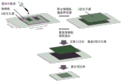
图1为本发明实施例提供的可拉伸电容器电极-导体结构的制备方法的流程图。FIG. 1 is a flow chart of a method for preparing a stretchable capacitor electrode-conductor structure according to an embodiment of the present invention.
图2为本发明实施例提供的可拉伸电容器电极-导体结构的制备方法的示意图。FIG. 2 is a schematic diagram of a method for preparing a stretchable capacitor electrode-conductor structure according to an embodiment of the present invention.
图3为本发明实施例提供的超顺排碳纳米管膜的扫描电子显微镜照片。FIG. 3 is a scanning electron microscope photograph of a superaligned carbon nanotube film provided in an embodiment of the present invention.
图4为本发明实施例1中的可拉伸电容器电极-导体结构的结构示意图。FIG. 4 is a schematic structural diagram of the electrode-conductor structure of the stretchable capacitor in Example 1 of the present invention.
图5为本发明实施例2中的可拉伸电容器电极-导体结构的结构示意图。FIG. 5 is a schematic structural diagram of the electrode-conductor structure of the stretchable capacitor in Example 2 of the present invention.
图6为本发明实施例1中可拉伸电容器电极-导体结构沿不同方向拉伸时电极电阻随应变变化的关系图。6 is a graph showing the relationship between the electrode resistance and the strain when the stretchable capacitor electrode-conductor structure is stretched in different directions in Example 1 of the present invention.
图7为本发明实施例提供的可拉伸超级电容器的结构示意图。FIG. 7 is a schematic structural diagram of a stretchable supercapacitor provided by an embodiment of the present invention.
图8为本发明实施例提供的可拉伸超级电容器沿不同方向拉伸时充放电循环性能图。FIG. 8 is a charge-discharge cycle performance diagram of the stretchable supercapacitor provided in an embodiment of the present invention when stretched in different directions.
图9为本发明实施例提供的可拉伸超级电容器沿不同方向的循环拉伸过程中,容量保持率随循环次数的变化曲线。FIG. 9 is a curve showing the change of the capacity retention rate with the number of cycles during the cyclic stretching process of the stretchable supercapacitor provided in the embodiment of the present invention along different directions.
图10为本发明实施例提供的可拉伸超级电容器初始状态和2000次不同方向循环拉伸后的充放电曲线。FIG. 10 is the initial state of the stretchable supercapacitor provided by the embodiment of the present invention and the charge-discharge curve after 2000 cycles of stretching in different directions.
图11为本发明实施例提供的可拉伸超级电容器在动态应变下的充放电曲线。FIG. 11 is a charge-discharge curve of the stretchable supercapacitor provided by an embodiment of the present invention under dynamic strain.
图12为本发明实施例提供的可拉伸电容器电极-导体结构的结构示意图。FIG. 12 is a schematic structural diagram of an electrode-conductor structure of a stretchable capacitor provided by an embodiment of the present invention.
图13为本发明实施例提供的可拉伸电容器电极-导体结构的竖切面示意图。FIG. 13 is a schematic vertical cross-sectional view of a stretchable capacitor electrode-conductor structure provided by an embodiment of the present invention.
主要元件符号说明Description of main component symbols
可拉伸电容器电极-导体结构10Stretchable Capacitor Electrode-
弹性基底102
电容器电极104
导体结构106
褶皱108
如下具体实施方式将结合上述附图进一步说明本发明。The following specific embodiments will further illustrate the present invention in conjunction with the above drawings.
具体实施方式Detailed ways
以下将结合附图及具体实施例,对本发明提供的可拉伸电容器电极-导体结构及采用该可拉伸电容器电极-导体结构的超级电容器作进一步详细说明。The stretchable capacitor electrode-conductor structure provided by the present invention and the supercapacitor using the stretchable capacitor electrode-conductor structure will be further described in detail below with reference to the accompanying drawings and specific embodiments.
请参阅图1和2,本发明实施例提供一种可拉伸电容器电极-导体结构的制备方法,包括以下步骤:1 and 2, an embodiment of the present invention provides a method for preparing a stretchable capacitor electrode-conductor structure, including the following steps:
步骤S1,提供一弹性基底,沿第一方向和第二方向对该弹性基底进行预拉伸,使所述弹性基底处于拉伸状态,该第一方向和第二方向交叉;Step S1, providing an elastic base, pre-stretching the elastic base along a first direction and a second direction, so that the elastic base is in a stretched state, and the first direction and the second direction intersect;
步骤S2,在所述弹性基底的表面铺设一碳纳米管活性物质复合层,具体包括以下步骤:Step S2, laying a carbon nanotube active material composite layer on the surface of the elastic substrate, which specifically includes the following steps:
S21,将一第一碳纳米管膜状结构铺设在处于拉伸状态的弹性基底的表面,该第一碳纳米管膜状结构包括多个超顺排碳纳米管膜,该多个超顺排碳纳米管膜层叠设置,每个超顺排碳纳米管膜包括多个碳纳米管,该多个碳纳米管基本沿同一方向延伸;S21, laying a first carbon nanotube film-like structure on the surface of the elastic substrate in a stretched state, where the first carbon nanotube film-like structure includes a plurality of super-aligned carbon nanotube films, the plurality of super-aligned carbon nanotube films The carbon nanotube films are arranged in layers, and each super-aligned carbon nanotube film includes a plurality of carbon nanotubes, and the plurality of carbon nanotubes extend substantially along the same direction;
S22,在所述第一碳纳米管膜状结构远离所述基底的表面覆盖一第一掩模板;S22, covering a first mask plate on the surface of the first carbon nanotube film-like structure away from the substrate;
S23,向所述第一碳纳米管膜状结构远离所述弹性基底的表面加入电极活性物质,在所述第一碳纳米管膜状结构的部分表面形成一第一活性物质层;S23, adding an electrode active material to the surface of the first carbon nanotube film-like structure away from the elastic substrate, and forming a first active material layer on a part of the surface of the first carbon nanotube film-like structure;
S24,移除所述第一掩模板;S24, removing the first mask;
S25,在所述第一活性物质层远离所述弹性基底的表面铺设一第二碳纳米管膜状结构,形成所述碳纳米管活性物质复合层,该第二碳纳米管膜状结构包括多个超顺排碳纳米管膜,该多个超顺排碳纳米管膜层叠设置,每个超顺排碳纳米管膜包括多个碳纳米管,该多个碳纳米管基本沿同一方向延伸;S25, laying a second carbon nanotube film-like structure on the surface of the first active material layer away from the elastic substrate to form the carbon nanotube active material composite layer, and the second carbon nanotube film-like structure includes multiple a plurality of super-aligned carbon nanotube films, the plurality of super-aligned carbon nanotube films are stacked and arranged, each super-aligned carbon nanotube film includes a plurality of carbon nanotubes, and the plurality of carbon nanotubes extend substantially in the same direction;
步骤S3,撤掉弹性基底的预拉伸使处于拉伸状态的弹性基底恢复到原始形态,在所述碳纳米管活性物质复合层的表面形成多个褶皱;以及Step S3, removing the pre-stretching of the elastic substrate to restore the elastic substrate in a stretched state to its original shape, and forming a plurality of wrinkles on the surface of the carbon nanotube active material composite layer; and
步骤S4,处理所述碳纳米管活性物质复合层,形成电容器电极和导体结构,该电容器电极和导体结构一体成型,进而得到所述可拉伸电容器电极-导体结构。In step S4, the carbon nanotube active material composite layer is processed to form a capacitor electrode and a conductor structure, and the capacitor electrode and the conductor structure are integrally formed, thereby obtaining the stretchable capacitor electrode-conductor structure.
步骤S1中,所述第一方向和第二方向的交叉角度不限。优选的,所述第一方向和第二方向垂直交叉,因为垂直交叉时可以使弹性基底在预拉伸时受力更均匀,当预拉伸撤掉时,在碳纳米管活性物质复合层表面形成的多个褶皱的分布以及褶皱的大小,形状等更加均匀,进而使可拉伸电容器电极-导体结构在任意方向被拉伸时,该多个褶皱可以在应变方向上均得到更好的伸展,提高可拉伸电容器电极-导体结构的耐不同方向拉伸的能力。本实施例中,所述第一方向和第二方向垂直交叉。In step S1, the intersection angle between the first direction and the second direction is not limited. Preferably, the first direction and the second direction intersect perpendicularly, because the perpendicular intersection can make the elastic substrate receive more uniform force during pre-stretching. When the pre-stretching is removed, the surface of the carbon nanotube active material composite layer is The distribution of the formed multiple wrinkles and the size and shape of the wrinkles are more uniform, so that when the stretchable capacitor electrode-conductor structure is stretched in any direction, the multiple wrinkles can be better stretched in the strain direction. , to improve the ability of the stretchable capacitor electrode-conductor structure to withstand stretching in different directions. In this embodiment, the first direction and the second direction intersect vertically.
可以理解,在其它实施例中,也可以沿三个或三个以上的方向对该弹性基底进行预拉伸,使所述弹性基底处于拉伸状态,三个或三个以上的方向对称且交叉设置。It can be understood that in other embodiments, the elastic substrate can also be pre-stretched in three or more directions, so that the elastic substrate is in a stretched state, and the three or more directions are symmetrical and intersecting set up.
所述弹性基底的材料可以为任意弹性材料。例如,所述弹性基底可选自硅橡胶、聚氯乙烯、聚四氟乙烯、聚氨酯(PU)、聚氯乙烯(PVC)、以及聚二甲基硅氧烷(PDMS)等。本实施例中,所述弹性基底为厚度为1mm的长方形的PDMS基底。The material of the elastic base can be any elastic material. For example, the elastic substrate may be selected from silicone rubber, polyvinyl chloride, polytetrafluoroethylene, polyurethane (PU), polyvinyl chloride (PVC), polydimethylsiloxane (PDMS), and the like. In this embodiment, the elastic substrate is a rectangular PDMS substrate with a thickness of 1 mm.
所述弹性基底可以在第一方向和第二方向上均进行双向预拉伸。该双向预拉伸是指该弹性基底在第一方向上分别朝两端进行预拉伸,在第二方向上分别朝两端进行预拉伸。可以理解,所述弹性基底在所述第一方向和第二方向上也可以均进行单向拉伸,即在所述第一方向上所述弹性基底的一端固定,仅对另一端进行预拉伸;在所述第二方向上所述弹性基底的一端固定,仅对另一端进行预拉伸。本实施例中,所述弹性基底沿第一方向和第二方向均进行双向拉伸,第一方向平行于长方形的长边长,第二方向平行于长方形的短边长。The elastic substrate may be biaxially pre-stretched in both the first and second directions. The bidirectional pre-stretching means that the elastic substrate is pre-stretched toward both ends in the first direction, respectively, and is pre-stretched toward both ends in the second direction. It can be understood that the elastic base can also be uniaxially stretched in both the first direction and the second direction, that is, one end of the elastic base is fixed in the first direction, and only the other end is pre-stretched stretch; one end of the elastic base is fixed in the second direction, and only the other end is pre-stretched. In this embodiment, the elastic base is biaxially stretched along both the first direction and the second direction, the first direction is parallel to the length of the long side of the rectangle, and the second direction is parallel to the length of the short side of the rectangle.
所述述弹性基底在第一方向和第二方向上的预拉伸量可以相等或不相等。本实施例中,所述弹性基底在第一方向和第二方向上的预拉伸量相等。该弹性基底在第一方向上的预拉伸量是指预拉伸之后弹性基底的沿第一方向的长度与原始形态下弹性基底沿第一方向的长度的百分比;该弹性基底在第二方向上的预拉伸量是指预拉伸之后弹性基底沿第二方向的长度与原始形态下弹性基底沿第二方向的长度的百分比。The amount of pre-stretching of the elastic substrate in the first direction and the second direction may be equal or unequal. In this embodiment, the amount of pre-stretching of the elastic substrate in the first direction and the second direction is equal. The amount of pre-stretching of the elastic base in the first direction refers to the percentage of the length of the elastic base in the first direction after pre-stretching to the length of the elastic base in the first direction in the original state; the elastic base in the second direction The pre-stretch amount on the upper side refers to the percentage of the length of the elastic substrate in the second direction after pre-stretching to the length of the elastic substrate in the original state in the second direction.
所述弹性基底的预拉伸量需控制在该弹性基底的弹性范围之内,所述弹性基底的预拉伸量可以根据该弹性基底的材料以及实际需要等进行设定。本实施例中,所述弹性基底为PDMS基底,在第一方向和第二方向上的预拉伸量大于等于150%小于等于400%。通过同时沿第一方向和第二方向对所述弹性基底施加外力进而对该弹性基底进行预拉伸,该外力的大小为使该弹性基底在不被破坏的情况下至少发生弹性变形的大小。本实施例中,通过一夹具对所述PDMS基底进行预拉伸。The pre-stretching amount of the elastic base needs to be controlled within the elastic range of the elastic base, and the pre-stretching amount of the elastic base can be set according to the material and actual needs of the elastic base. In this embodiment, the elastic substrate is a PDMS substrate, and the pre-stretching amount in the first direction and the second direction is greater than or equal to 150% and less than or equal to 400%. The elastic substrate is pre-stretched by applying an external force along the first direction and the second direction at the same time, the magnitude of the external force is such that the elastic substrate is at least elastically deformed without being damaged. In this embodiment, the PDMS substrate is pre-stretched by a fixture.
步骤S21中,优选的,所述第一碳纳米管膜状结构中的多个超顺排碳纳米管膜中,相邻的两个超顺排碳纳米管膜中的碳纳米管交叉设置。此时,所述多个超顺排碳纳米管膜中,会形成一网格结构,当第一碳纳米管膜状结构受到拉伸时,该网格结构可以通过自身的变形吸收一定的应变,可以在一定的范围内保持自身导电网络的完整,进而不易被拉断,可以减慢电阻的增加速度。相邻的两个超顺排碳纳米管膜中碳纳米管的交叉角度不限。本实施例中,相邻的两个超顺排碳纳米管膜中碳纳米管的交叉角度为90度。In step S21, preferably, in the plurality of super-aligned carbon nanotube films in the first carbon nanotube film-like structure, carbon nanotubes in two adjacent super-aligned carbon nanotube films are crossed. At this time, a grid structure will be formed in the plurality of super-aligned carbon nanotube films. When the first carbon nanotube film-like structure is stretched, the grid structure can absorb a certain strain through its own deformation. , it can maintain the integrity of its own conductive network within a certain range, and it is not easy to be pulled off, which can slow down the increase of resistance. The intersection angle of carbon nanotubes in two adjacent superaligned carbon nanotube films is not limited. In this embodiment, the intersection angle of carbon nanotubes in two adjacent super-aligned carbon nanotube films is 90 degrees.
所述超顺排碳纳米管膜的制备方法包括:The preparation method of the super-aligned carbon nanotube film includes:
首先,提供一超顺排碳纳米管阵列,该超顺排碳纳米管阵列形成于一基板的表面。该超顺排碳纳米管阵列由多个碳纳米管组成,且该多个碳纳米管基本上相互平行且垂直于所述基板的表面,该超顺排碳纳米管阵列基本不含杂质,如无定型碳或残留的催化剂金属颗粒等。所述超顺排碳纳米管阵列的制备方法可参见中国大陆专利申请公开第02134760.3号。First, a superaligned carbon nanotube array is provided, and the superaligned carbon nanotube array is formed on the surface of a substrate. The super-aligned carbon nanotube array is composed of a plurality of carbon nanotubes, and the plurality of carbon nanotubes are substantially parallel to each other and perpendicular to the surface of the substrate, the super-aligned carbon nanotube array is substantially free of impurities, such as Amorphous carbon or residual catalyst metal particles, etc. For the preparation method of the superaligned carbon nanotube array, please refer to Chinese Mainland Patent Application Publication No. 02134760.3.
其次,采用一拉伸工具从所述超顺排碳纳米管阵列中选定多个碳纳米管,本实施例优选为采用具有一定宽度的胶带或粘性基条接触该超顺排碳纳米管阵列以选定具有一定宽度的多个碳纳米管;以一定速度拉伸该选定的碳纳米管,该拉取方向沿基本垂直于超顺排碳纳米管阵列的生长方向。从而形成首尾相连的多个碳纳米管,进而形成一连续的超顺排碳纳米管膜。该超顺排碳纳米管膜中的多个碳纳米管定向排列且通过范德华力首尾相连。该超顺排碳纳米管膜中碳纳米管的排列方向基本平行于该超顺排碳纳米管膜的拉伸方向。Next, a drawing tool is used to select a plurality of carbon nanotubes from the super-aligned carbon nanotube array. In this embodiment, preferably, a tape or adhesive base with a certain width is used to contact the super-aligned carbon nanotube array. selecting a plurality of carbon nanotubes having a certain width; and drawing the selected carbon nanotubes at a speed in a direction substantially perpendicular to the growth direction of the superaligned carbon nanotube array. Thus, a plurality of carbon nanotubes connected end to end are formed, thereby forming a continuous super-aligned carbon nanotube film. A plurality of carbon nanotubes in the super-aligned carbon nanotube film are aligned and connected end to end by van der Waals force. The alignment direction of the carbon nanotubes in the super-aligned carbon nanotube film is substantially parallel to the stretching direction of the super-aligned carbon nanotube film.
请参见图3,所述超顺排碳纳米管膜由若干碳纳米管组成。所述若干碳纳米管基本沿同一方向择优取向排列,所述择优取向排列是指在超顺排碳纳米管膜中大多数碳纳米管的整体延伸方向基本朝同一方向。而且,所述大多数碳纳米管的整体延伸方向基本平行于超顺排碳纳米管膜的表面。当然,所述超顺排碳纳米管膜中存在少数随机排列的碳纳米管,这些碳纳米管不会对超顺排碳纳米管膜中大多数碳纳米管的整体取向排列构成明显影响。具体地,所述超顺排碳纳米管膜中基本朝同一方向延伸的多数碳纳米管,并非绝对的直线状,可以适当的弯曲;或者并非完全按照延伸方向上排列,可以适当的偏离延伸方向。因此,不能排除所述超顺排碳纳米管膜中基本朝同一方向延伸的多数碳纳米管中并列的碳纳米管之间可能存在部分接触。Referring to FIG. 3 , the super-aligned carbon nanotube film is composed of several carbon nanotubes. The plurality of carbon nanotubes are arranged in a preferred orientation substantially in the same direction, and the preferred orientation arrangement means that the overall extension direction of most of the carbon nanotubes in the super-aligned carbon nanotube film is substantially in the same direction. Moreover, the overall extension direction of the majority of carbon nanotubes is substantially parallel to the surface of the superaligned carbon nanotube film. Certainly, there are a few randomly arranged carbon nanotubes in the super-aligned carbon nanotube film, and these carbon nanotubes do not significantly affect the overall orientation of most carbon nanotubes in the super-aligned carbon nanotube film. Specifically, most of the carbon nanotubes in the super-aligned carbon nanotube film extending in the same direction are not absolutely straight, and can be appropriately bent; or are not completely arranged in the extending direction, and can be appropriately deviated from the extending direction. . Therefore, it cannot be ruled out that there may be partial contact between the juxtaposed carbon nanotubes in the plurality of carbon nanotubes extending substantially in the same direction in the super-aligned carbon nanotube film.
可以在所述超顺排碳纳米管阵列中拉取所述超顺排碳纳米管膜之后直接铺设在处于拉伸状态的弹性基底的表面,即直接在处于拉伸状态的弹性基底的表面形成所述第一碳纳米管膜状结构。具体地,在一超顺排碳纳米管阵列中拉取一第一超顺排碳纳米管膜直接铺设在处于拉伸状态的弹性基底的表面;在所述超顺排碳纳米管阵列拉取一第二超顺排碳纳米管膜直接铺设在所述第一超顺排碳纳米管膜的表面,并使该第二超顺排碳纳米管膜和所述第一超顺排碳纳米管膜层叠且交叉设置;以此类推,直至形成所述第一碳纳米管膜状结构。可以理解,也可以将所述多个超顺排碳纳米管膜层叠且交叉设置形成所述第一碳纳米管膜状结构之后,再将该第一碳纳米管膜状结构铺设在处于拉伸状态的弹性基底的表面。After the super-aligned carbon nanotube film is drawn from the super-aligned carbon nanotube array, it can be directly laid on the surface of the stretched elastic substrate, that is, directly formed on the surface of the stretched elastic substrate. The first carbon nanotube film-like structure. Specifically, a first super-aligned carbon nanotube film is drawn from a super-aligned carbon nanotube array and directly laid on the surface of the elastic substrate in a stretched state; A second super-aligned carbon nanotube film is directly laid on the surface of the first super-aligned carbon nanotube film, and makes the second super-aligned carbon nanotube film and the first super-aligned carbon nanotube film The films are stacked and crossed; and so on, until the first carbon nanotube film-like structure is formed. It can be understood that the first carbon nanotube film-like structure can also be formed by stacking and intersecting the plurality of super-aligned carbon nanotube films, and then laying the first carbon nanotube film-like structure under tension. state of the surface of the elastic substrate.
所述第一碳纳米管膜状结构中碳纳米管的延伸方向与所述第一方向和第二方向的夹角不限。本实施例中,所述第一碳纳米管膜状结构中碳纳米管的延伸方向与所述第一方向或第二方向平行。The angle between the extending direction of the carbon nanotubes in the first carbon nanotube film-like structure and the first direction and the second direction is not limited. In this embodiment, the extending direction of the carbon nanotubes in the first carbon nanotube film-like structure is parallel to the first direction or the second direction.
由于所述第一碳纳米管膜状结构比较纯净,基本不含杂质,因此该碳纳米管活性物质复合层可以通过该第一碳纳米管膜状结构自身的粘性固定在所述弹性基底的表面。Since the first carbon nanotube film-like structure is relatively pure and basically free of impurities, the carbon nanotube active material composite layer can be fixed on the surface of the elastic substrate through the viscosity of the first carbon nanotube film-like structure itself .
步骤S22中,所述第一掩模板的材料不限。所述第一掩模板为图案化掩模板,用于使第一活性物质通过该第一掩模板之后形成在所述第一碳纳米管膜状结构上。优选的,该第一掩模板上的图案的大小和形状分别根据电容器两个电极的大小和形状进行设计,此时,将所述碳纳米管活性物质复合层中碳纳米管/活性物质复合膜部分切割为电容器电极形状的步骤可以省略。本实施例中,所述掩模板为一具有两个孔洞的聚乙烯薄膜,该两个孔洞根据电极的大小和形状进行切割。In step S22, the material of the first mask is not limited. The first mask plate is a patterned mask plate, and is used for forming a first active material on the first carbon nanotube film-like structure after passing through the first mask plate. Preferably, the size and shape of the pattern on the first mask plate are designed according to the size and shape of the two electrodes of the capacitor. At this time, the carbon nanotube/active material composite film in the carbon nanotube active material composite layer is The step of partially cutting into the shape of the capacitor electrodes can be omitted. In this embodiment, the mask is a polyethylene film with two holes, and the two holes are cut according to the size and shape of the electrodes.
步骤S23中,所述第一活性物质层的材料可以为任意的电容器电极活性材料或者是活性物质前驱体材料。所述电容器电极活性材料可以为活性炭(AC)、二氧化锰、二氧化钌等。所述活性物质前驱体材料可以为硝酸锰等。In step S23, the material of the first active material layer may be any capacitor electrode active material or active material precursor material. The capacitor electrode active material may be activated carbon (AC), manganese dioxide, ruthenium dioxide and the like. The active material precursor material may be manganese nitrate or the like.
步骤S25中,优选的,所述第二碳纳米管膜状结构中的多个超顺排碳纳米管膜中,相邻的两个超顺排碳纳米管膜中的碳纳米管交叉设置。相邻的两个超顺排碳纳米管膜中碳纳米管的交叉角度不限。本实施例中,相邻的两个超顺排碳纳米管膜中碳纳米管的交叉角度为90度。In step S25, preferably, among the plurality of super-aligned carbon nanotube films in the second carbon nanotube film-like structure, carbon nanotubes in two adjacent super-aligned carbon nanotube films are crossed. The intersection angle of carbon nanotubes in two adjacent superaligned carbon nanotube films is not limited. In this embodiment, the intersection angle of carbon nanotubes in two adjacent super-aligned carbon nanotube films is 90 degrees.
向所述第一碳纳米管膜状结构远离所述弹性基底的表面加入电极活性物质的具体方法包括:将电极活性物质分散到一易挥发有机溶剂中形成一混合溶液;将所述混合溶液通过掩模板的孔洞均匀滴加到所述第一碳纳米管膜状结构的部分表面,待所述易挥发的有机溶剂蒸发至无明显液滴后,形成所述第一活性物质层。本实施例中,将电极活性物质使用细胞粉碎机分散在乙醇中,分散一段时间之后,使用移液枪取少量的分散液均匀滴加到第一碳纳米管膜状结构上。The specific method for adding electrode active material to the surface of the first carbon nanotube film-like structure away from the elastic substrate includes: dispersing the electrode active material into a volatile organic solvent to form a mixed solution; passing the mixed solution through The holes of the mask plate are uniformly dropped onto a part of the surface of the first carbon nanotube film structure, and the first active material layer is formed after the volatile organic solvent is evaporated to no obvious droplets. In this embodiment, the electrode active material is dispersed in ethanol using a cell crusher, and after dispersing for a period of time, a small amount of the dispersion liquid is uniformly dropped onto the first carbon nanotube film-like structure using a pipette gun.
第一碳纳米管膜状结构中层叠设置的超顺排碳纳米管膜可以形成多个微孔,当所述第一活性层中的活性物质颗粒尺寸小于该微孔的尺寸时,该第一活性层可以部分嵌入到所述第一碳纳米管膜状结构中。The super-aligned carbon nanotube films stacked in the first carbon nanotube film-like structure can form a plurality of micropores, and when the particle size of the active material in the first active layer is smaller than the size of the micropores, the first The active layer may be partially embedded in the first carbon nanotube film-like structure.
可以理解,在步骤S25之后S3之前可进一步包括:步骤S26:在所述第二碳纳米管膜状结构远离所述弹性基底的表面覆盖一第二掩模板,向所述第二碳纳米管膜状结构远离所述弹性基底的表面加入所述活性物质,在所述第二碳纳米管膜状结构的部分表面形成一第二活性物质层;移除所述第二掩模板;以及在所述第二活性物质层远离所述弹性基底的表面铺设一第三碳纳米管膜状结构,该第三碳纳米管膜状结构包括多个超顺排碳纳米管膜,该多个超顺排碳纳米管膜层叠设置;以此类推,多次重复步骤S26。该第二活性物质层的材料以及加入方法均与第一活性物质层相同。第一掩模板的覆盖位置与第二掩模板的覆盖位置相同,即第一掩模板中的孔洞位置与第二掩模板中的孔洞位置是重叠的。优选的,所述第三碳纳米管膜状结构中的多个超顺排碳纳米管膜中,相邻的两个超顺排碳纳米管膜中的碳纳米管交叉设置。It can be understood that, after step S25 and before step S3, it may further include: step S26 : covering a second mask plate on the surface of the second carbon nanotube film-like structure away from the elastic substrate, to cover the surface of the second carbon nanotube film to the second carbon nanotube film adding the active material to the surface of the second carbon nanotube film-like structure away from the elastic substrate, forming a second active material layer on part of the surface of the second carbon nanotube film-like structure; removing the second mask; A third carbon nanotube film-like structure is laid on the surface of the second active material layer away from the elastic substrate. The third carbon nanotube film-like structure includes a plurality of super-aligned carbon nanotube films. The plurality of super-aligned carbon nanotube films The nanotube films are stacked; and so on, repeat step S26 multiple times. The material and adding method of the second active material layer are the same as those of the first active material layer. The covering position of the first mask plate is the same as that of the second mask plate, that is, the positions of the holes in the first mask plate and the holes in the second mask plate overlap. Preferably, in the plurality of super-aligned carbon nanotube films in the third carbon nanotube film-like structure, the carbon nanotubes in two adjacent super-aligned carbon nanotube films are crossed.
整个可拉伸电容器电极-导体结构中,活性物质层包裹在层状的碳纳米管膜状结构之间,形成层状的三明治结构。每个碳纳米管膜状结构中超顺排碳纳米管膜的数量可以相等也可以不相等的。优选的,第一碳纳米管膜状结构与最外层的碳纳米管膜状结构中的超顺排碳纳米管膜的数量大于中间层的碳纳米管膜状结构中超顺排碳纳米管膜的数量,这样可以更好的对活性物质层进行承载,最外层的碳纳米管膜状结构是指与弹性基底距离最远的碳纳米管膜状结构。本实施例中,9次重复步骤S26,得到的碳纳米管活性物质复合层中共包括12层碳纳米管膜状结构和11层活性物质层,其中第一碳纳米管膜状结构中和最外层的碳纳米管膜状结构均由6层超顺排碳纳米管膜组成,中间的碳纳米管膜状结构均由2层超顺排碳纳米管膜组成。In the whole stretchable capacitor electrode-conductor structure, the active material layer is wrapped between the layered carbon nanotube film structures to form a layered sandwich structure. The number of super-aligned carbon nanotube films in each carbon nanotube film-like structure may be equal or unequal. Preferably, the number of super-aligned carbon nanotube films in the first carbon nanotube film-like structure and the outermost carbon nanotube film-like structure is greater than the number of super-aligned carbon nanotube films in the carbon nanotube film-like structure of the middle layer In this way, the active material layer can be better supported, and the outermost carbon nanotube film-like structure refers to the carbon nanotube film-like structure with the farthest distance from the elastic substrate. In this embodiment, step S26 is repeated 9 times, and the obtained carbon nanotube active material composite layer includes a total of 12 layers of carbon nanotube film-like structures and 11 layers of active material layers, wherein the first carbon nanotube film-like structure is in the middle and the outermost layer. The carbon nanotube film-like structures of the layers are all composed of six layers of super-aligned carbon nanotube films, and the carbon nanotube film-like structures in the middle are all composed of two layers of super-aligned carbon nanotube films.
步骤S3中,由于所述碳纳米管活性物质复合层粘结于所述弹性基底的表面,当去除弹性基底的预拉伸之后,所述弹性基底沿第一方向和第二方向方向上的长度均会缩短,碳纳米管活性物质复合层中的碳纳米管将在该碳纳米管活性物质复合层的法线方向向上弯曲形成多个突起的褶皱,也就是说,该碳纳米管活性物质复合层的某一部分已经高出其他部分。所述碳纳米管活性物质复合层表面形成波浪状的起伏结构,包括多个褶皱,表面呈褶皱状态。该可拉伸电容器电极-导体结构沿任意方向被拉伸时,该多个褶皱可以在应变方向上展开,吸收应变,碳纳米管活性物质复合层中的碳纳米管不会断开,保持可拉伸电容器电极-导体结构的完整性。尤其是当该可拉伸电容器电极-导体结构沿不同方向同时被拉伸时,该多个褶皱可以在不同的应变方向上同时展开,吸收应变,碳纳米管活性物质复合层中的碳纳米管不会断开,保持碳纳米管活性物质复合层的完整性。如果应变小于等于所述弹性基底的预拉伸量,则碳纳米管活性物质复合层表面的褶皱结构的形变可逆。In step S3, since the carbon nanotube active material composite layer is bonded to the surface of the elastic substrate, after the pre-stretching of the elastic substrate is removed, the length of the elastic substrate along the first direction and the second direction is will shorten, and the carbon nanotubes in the carbon nanotube active material composite layer will be bent upward in the normal direction of the carbon nanotube active material composite layer to form a plurality of protruding folds, that is, the carbon nanotube active material composite layer. Some parts of the layer are already higher than others. A wavy undulating structure is formed on the surface of the carbon nanotube active material composite layer, including a plurality of wrinkles, and the surface is in a wrinkled state. When the stretchable capacitor electrode-conductor structure is stretched in any direction, the plurality of folds can be unfolded in the strain direction to absorb the strain, the carbon nanotubes in the carbon nanotube active material composite layer will not be disconnected, and the Integrity of electrode-conductor structures in tensile capacitors. Especially when the stretchable capacitor electrode-conductor structure is simultaneously stretched in different directions, the plurality of folds can be simultaneously unfolded in different strain directions, absorbing strain, the carbon nanotubes in the carbon nanotube active material composite layer It will not break, maintaining the integrity of the carbon nanotube active material composite layer. If the strain is less than or equal to the pre-stretching amount of the elastic substrate, the deformation of the wrinkled structure on the surface of the carbon nanotube active material composite layer is reversible.
在步骤S4中,所述处理所述碳纳米管活性物质复合层的方法包括将所述碳纳米管活性物质复合层中碳纳米管/活性物质复合膜部分切割为电容器电极,将碳纳米管活性物质复合层中纯碳纳米管部分切割成导体结构,得到所述可拉伸电容器电极-导体结构。In step S4, the method for processing the carbon nanotube active material composite layer includes cutting the carbon nanotube/active material composite film part of the carbon nanotube active material composite layer into a capacitor electrode, and cutting the carbon nanotube active material composite layer into a capacitor electrode, The pure carbon nanotubes in the material composite layer are partially cut into conductor structures to obtain the stretchable capacitor electrode-conductor structure.
可以采用激光将所述碳纳米管活性物质复合层中碳纳米管/活性物质复合膜部分切割为电容器电极,将碳纳米管活性物质复合层中纯碳纳米管部分切割成导体结构,得到所述可拉伸电容器电极-导体结构。The carbon nanotube/active material composite film part in the carbon nanotube active material composite layer can be cut into a capacitor electrode by a laser, and the pure carbon nanotube part in the carbon nanotube active material composite layer can be cut into a conductor structure to obtain the described Stretchable capacitor electrode-conductor structure.
所述导体结构的形状不限,可以根据实际需要进行切割。The shape of the conductor structure is not limited, and can be cut according to actual needs.
在步骤S4之后,可进一步包括将所述弹性基底去除的步骤,进而使得到的可拉伸电容器电极-导体结构不包括弹性基底。After step S4, a step of removing the elastic substrate may be further included, so that the obtained stretchable capacitor electrode-conductor structure does not include an elastic substrate.
实施例1:Example 1:
本实施例中,制备一可拉伸电容器电极-导体结构,其中电容器电极部分包括PDMS、超顺排碳纳米管膜以及AC,导体部分为纯碳纳米管。其制备方法包括:提供一PDMS基底,分别沿长方形PDMS基底的长和宽对该PDMS基底进行150%预拉伸;然后将铺在75mm×75mm的铝合金框上的6层超顺排碳纳米管交叉膜覆盖到拉伸状态下的PDMS基底上;在6层超顺排碳纳米管交叉膜覆盖一聚乙烯薄膜作为掩模板;将45mg活性炭粉末使用细胞粉碎机分散在60mL乙醇中形成一分散液,使用移液枪取6mL分散液均匀滴加到覆盖掩模板的所述6层超顺排碳纳米管交叉膜的部分表面上,待乙醇蒸发至无明显液滴后形成AC活性物质层,移除所述掩模板;在AC活性物质层上覆盖2层超顺排碳纳米管交叉膜,在该2层超顺排碳纳米管交叉膜覆盖聚乙烯薄膜作为掩模板,使用移液枪取6mL分散液均匀滴加到覆盖掩模板的2层超顺排碳纳米管交叉膜上,待乙醇蒸发至无明显液滴后形成AC活性物质层,移除所述掩模板,重复该步骤9次;最后再覆盖一层6层超顺排碳纳米管交叉膜;待乙醇蒸发至无明显液滴后,撤去加载至PDMS基底上的外力,在保证PDMS基底完整性的基础上,采用激光将纯碳纳米管部分切割成如图4所述的导体结构。得到的碳纳米管活性物质复合层中共包括12层碳纳米管膜状结构和11层活性物质层,其中第一碳纳米管膜状结构中和最外层的碳纳米管膜状结构均由6层超顺排碳纳米管膜组成,中间的碳纳米管膜状结构均由2层超顺排碳纳米管膜组成。本实施例中含有活性物质部分的活性炭的面密度约为5mg/cm3。In this embodiment, a stretchable capacitor electrode-conductor structure is prepared, wherein the capacitor electrode part includes PDMS, super-aligned carbon nanotube film and AC, and the conductor part is pure carbon nanotubes. The preparation method includes: providing a PDMS substrate, pre-stretching the PDMS substrate by 150% along the length and width of the rectangular PDMS substrate respectively; The tube cross film was covered on the stretched PDMS substrate; the 6-layer super-aligned carbon nanotube cross film was covered with a polyethylene film as a mask; 45 mg of activated carbon powder was dispersed in 60 mL of ethanol using a cell crusher to form a dispersion liquid, use a pipette to take 6mL of the dispersion and evenly drop it on the part of the surface of the 6-layer super-aligned carbon nanotube cross film covering the mask plate, and after the ethanol evaporates until there are no obvious droplets, an AC active material layer is formed, Remove the mask; cover the AC active material layer with 2 layers of super-aligned carbon nanotube cross film, cover the two layers of super-aligned carbon nanotube cross film with a polyethylene film as a mask, and use a pipette to take it. 6mL of dispersion liquid was evenly added dropwise to the 2-layer super-aligned carbon nanotube cross film covering the mask plate, and the AC active material layer was formed after the ethanol was evaporated to no obvious droplets, the mask plate was removed, and this step was repeated 9 times ; Finally, cover a layer of 6 layers of super-aligned carbon nanotube cross film; after the ethanol evaporates to no obvious droplets, remove the external force loaded on the PDMS substrate, and on the basis of ensuring the integrity of the PDMS substrate, the pure The carbon nanotubes are partially cut into conductor structures as described in FIG. 4 . The obtained carbon nanotube active material composite layer includes a total of 12 layers of carbon nanotube film-like structures and 11 layers of active material layers, wherein the carbon nanotube film-like structures in the first carbon nanotube film-like structure and the outermost layer are composed of 6 layers. The carbon nanotube film in the middle is composed of two layers of super-aligned carbon nanotube films. The surface density of the activated carbon containing the active material portion in this example was about 5 mg/cm 3 .
实施例2:Example 2:
本实施例与实施例1的区别仅在于纯碳纳米管部分切割成的导体结构不同。请参阅图5。The difference between this embodiment and Embodiment 1 is only in that the conductor structures formed by partially cutting pure carbon nanotubes are different. See Figure 5.
对比例1:Comparative Example 1:
本对比例中,也制备一可拉伸电容器电极-导体结构,其中电容器电极部分包括PDMS、超顺排碳纳米管膜以及AC,导体部分为纯碳纳米管,其制备方法与实施例1基本相同,其不同仅在于本对比例中的PDMS基底未经过预拉伸处理。In this comparative example, a stretchable capacitor electrode-conductor structure is also prepared, wherein the capacitor electrode part includes PDMS, super-aligned carbon nanotube film and AC, and the conductor part is pure carbon nanotubes. The preparation method is basically the same as that of Example 1. The same, the only difference is that the PDMS substrate in this comparative example is not pre-stretched.
请参阅图6,实施例1的复合结构分别在X、Y、45°以及30°轴向进行0~150%拉伸之后,实施例1中的电容器电极的电阻仅有微小的增加。当应变达到150%时,实施例1的电容器电极沿X、Y、45°、30°轴向拉伸的轴向电阻仅分别增加6.5%、6%、5.9%以及5.1%。然而,对比例1中未经预拉伸的电容器电极在沿碳管束轴向拉伸时电阻迅速增加,40%应变下电阻增加就达到了50%。说明相比于未进行预拉伸的电容器电极-导体结构,经过双向预拉伸处理的电容器电极-导体结构在不同方向0~150%应变下都保持了良好的电阻稳定性,进而说明通过双向预拉伸的工艺,能够大幅度提高可拉伸电容器电极-导体结构的各个方向上的应变承受能力,获得电阻稳定的可拉伸电容器电极-导体结构。Referring to FIG. 6 , after the composite structure of Example 1 is stretched by 0-150% in the X, Y, 45° and 30° axes, the resistance of the capacitor electrode in Example 1 only increases slightly. When the strain reaches 150%, the axial resistance of the capacitor electrode of Example 1 stretched along the X, Y, 45°, 30° axial directions only increases by 6.5%, 6%, 5.9% and 5.1%, respectively. However, the non-pre-stretched capacitor electrode in Comparative Example 1 rapidly increased in resistance when stretched along the axial direction of the carbon tube bundle, and the increase in resistance reached 50% at 40% strain. It shows that compared with the capacitor electrode-conductor structure without pre-stretching, the capacitor electrode-conductor structure after bidirectional pre-stretching maintains good resistance stability under 0-150% strain in different directions. The pre-stretching process can greatly improve the strain bearing capacity of the stretchable capacitor electrode-conductor structure in all directions, and obtain a stretchable capacitor electrode-conductor structure with stable resistance.
请参阅图7,将实施例1和实施例2的可拉伸电容器电极-导体结构串联制备一可拉伸超级电容器。在实施例1和2中的可拉伸电容器电极-导体结构的电容器电极部分分别均匀涂敷一层凝胶电解质,采用70℃左右烘箱烘干约1h后;将实施例2中的可拉伸电容器电极-导体结构与该实施例1中可拉伸电容器电极-导体结构粘贴在一起,实施例1中的电容器电极部分与实施例2中的电容器电极部分对准,使凝胶电解质位于实施例1的电容器电极和实施例2的电容器电极中间;排除其中所有气体后,使用PDMS将周围密封,待PDMS固化后即可得到可拉伸超级电容器。Referring to FIG. 7 , a stretchable supercapacitor is prepared by connecting the stretchable capacitor electrode-conductor structures of Example 1 and Example 2 in series. A layer of gel electrolyte was evenly coated on the capacitor electrode part of the stretchable capacitor electrode-conductor structure in Examples 1 and 2, and dried in an oven at about 70°C for about 1 hour; The capacitor electrode-conductor structure is glued together with the stretchable capacitor electrode-conductor structure in this Example 1, the capacitor electrode part in Example 1 is aligned with the capacitor electrode part in Example 2, and the gel electrolyte is located in the example Between the capacitor electrode of 1 and the capacitor electrode of Example 2; after removing all the gas, the surrounding area is sealed with PDMS, and the stretchable supercapacitor can be obtained after the PDMS is cured.
所述凝胶电解质使用水系凝胶电解质。该水系凝胶电解质的制备方法包括,将0.6g聚乙烯醇(PVA)在80℃左右溶解于6g去离子水中,然后添加0.6g 1M的磷酸(H3PO4),搅拌约5小时至形成均匀凝胶状电解质。As the gel electrolyte, an aqueous gel electrolyte is used. The preparation method of the aqueous gel electrolyte includes dissolving 0.6 g of polyvinyl alcohol (PVA) in 6 g of deionized water at about 80° C., then adding 0.6 g of 1M phosphoric acid (H3PO4), and stirring for about 5 hours to form a uniform gel shaped electrolyte.
请参阅图8,为所述可拉伸超级电容器恒流充放电的循环曲线,以及将可拉伸超级电容器沿不同方向拉伸至150%应变后的恒流充放电循环曲线。由图中可以看出,该可拉伸超级电容器在恒流充放电循环中具有良好的容量保持率,1000次充放电循环后容量保持率接近100%,说明该可拉伸超级电容器具有很好的耐拉伸循环能力。相比较于未拉伸状态下的可拉伸超级电容器,X、Y、45°方向150%应变下的可拉伸超级电容器拉伸后容量保持率分别可以达到96.7%,97.8%以及98.9%,说明该可拉伸超级电容器具有良好的抗大应变拉伸能力。由图中还可以看出,未拉伸状态下的超级电容器比容量为0.91F/g,说明实施例1和2中的电容器复合电极具有了良好的电化学性能,这是因为该电极是在纯碳纳米管表面吸附的活性炭。Please refer to FIG. 8 , which is the constant current charge-discharge cycle curve of the stretchable supercapacitor, and the constant current charge-discharge cycle curve after the stretchable supercapacitor is stretched to 150% strain in different directions. It can be seen from the figure that the stretchable supercapacitor has a good capacity retention rate in constant current charge-discharge cycles, and the capacity retention rate is close to 100% after 1000 charge-discharge cycles, indicating that the stretchable supercapacitor has a good capacity retention rate. resistance to stretch cycling. Compared with the stretchable supercapacitor in the unstretched state, the capacity retention rate of the stretchable supercapacitor under 150% strain in the X, Y, and 45° directions can reach 96.7%, 97.8% and 98.9%, respectively. It shows that the stretchable supercapacitor has a good ability to resist large strain. It can also be seen from the figure that the specific capacity of the supercapacitor in the unstretched state is 0.91 F/g, indicating that the capacitor composite electrodes in Examples 1 and 2 have good electrochemical performance, because the electrodes are in Activated carbon adsorbed on the surface of pure carbon nanotubes.
请参阅图9,对所述可拉伸超级电容器沿不同轴向进行了2000次0~150%应变的往复拉伸,拉伸速度为1%/s。由图中可以看出,该可拉伸超级电容器经过2000次X、Y、45°轴向拉伸之后,容量保持率分别为97%、98.5%以及98.6%。说明该可拉伸超级电容器对不同方向的反复大应变拉伸有良好的耐受性。Referring to FIG. 9 , the stretchable supercapacitor was stretched 2000 times along different axial directions with a strain of 0-150%, and the stretching speed was 1%/s. It can be seen from the figure that after 2000 times of X, Y, and 45° axial stretching of the stretchable supercapacitor, the capacity retention rates are 97%, 98.5%, and 98.6%, respectively. It shows that the stretchable supercapacitor has good resistance to repeated large strain stretching in different directions.
请参阅图10,可以看出,所述可拉伸超级电容器沿不同轴向150%应变拉伸2000次循环后的充放电曲线与未经拉伸时可拉伸超级电容器的充放电曲线几乎完全一致。说明不同轴向的反复拉伸对该种可拉伸超级电容器的电极结构几乎没有影响。Referring to Fig. 10, it can be seen that the charge-discharge curves of the stretchable supercapacitor after being stretched with 150% strain along different axes for 2000 cycles are almost the same as those of the stretchable supercapacitor without stretching. Consistent. It shows that repeated stretching in different axial directions has little effect on the electrode structure of this stretchable supercapacitor.
请参阅图11,为了测试可拉伸超级电容器充放电曲线充放电过程中对应变的响应能力,在充放电过程中对可拉伸超级电容器进行了动态的拉伸。在对可拉伸超级电容器进行0.5A/g充放电的同时,对其沿不同方向以7.5%/s的速度加载0~150%的循环应变。由图中可以看出,在循环应变加载的过程中,可拉伸超级电容器充放电的过程几乎没有受到循环应变的影响,依然保持了与静态可拉伸超级电容器相同的充放电曲线。X、Y、45°方向的循环应变下可拉伸超级电容器比容量保持率分别达到了94%、96%以及97%,说明该可拉伸超级电容器对不同方向循环应变具有良好的耐受能力。Referring to Fig. 11, in order to test the responsiveness of the charge-discharge curve of the stretchable supercapacitor to strain during charging and discharging, the stretchable supercapacitor was dynamically stretched during the charging and discharging process. While charging and discharging the stretchable supercapacitor at 0.5 A/g, it was loaded with 0-150% cyclic strain along different directions at a rate of 7.5%/s. It can be seen from the figure that in the process of cyclic strain loading, the charge-discharge process of the stretchable supercapacitor is hardly affected by the cyclic strain and still maintains the same charge-discharge curve as the static stretchable supercapacitor. The specific capacity retention rates of the stretchable supercapacitor under cyclic strain in the X, Y, and 45° directions reached 94%, 96%, and 97%, respectively, indicating that the stretchable supercapacitor has good tolerance to cyclic strains in different directions. .
请参阅图12,本发明实施例还提供一种采用上述制备方法得到的可拉伸电容器电极-导体结构10,该可拉伸电容器电极-导体结构10包括:弹性基底102,电容器电极104以及导体结构106,该电容器电极104以及导体结构106均设置在所述弹性基底102的表面,且该电容器电极104与该导体结构106一体成型。该电容器电极104包括多个碳纳米管层层叠设置,相邻的两个碳纳米管层之间设置有活性物质,每个碳纳米管层包括至少两层超顺排碳纳米管膜,该至少两层超顺排碳纳米管膜层叠设置,每个超顺排碳纳米管膜包括多个碳纳米管,该多个碳纳米管基本沿同一方向延伸。该导体结构106包括多个超顺排碳纳米管膜,该多个超顺排碳纳米管膜层叠设置。每个超顺排碳纳米管膜包括多个碳纳米管,该多个碳纳米管基本沿同一方向延伸。请参阅图13,所述可拉伸电容器电极-导体结构10的表面具有多个褶皱108。该多个褶皱108是指在可拉伸电容器电极-导体结构10的法线方向向上弯曲形成多个突起,也就是说,该电容器电极104以及导体结构106的某一部分已经高出其它部分。该可拉伸电容器电极-导体结构10沿任意方向被拉伸时,该多个褶皱108可以在应变方向上展开,吸收应变,碳纳米管层中的碳纳米管不会断开,保持可拉伸电容器电极-导体结构的完整性。尤其是当该可拉伸电容器电极-导体结构沿不同方向同时被拉伸时,该多个褶皱可以在不同的应变方向上同时展开,吸收应变,碳纳米管层中的碳纳米管不会断开,保持可拉伸电容器电极-导体结构的完整性。如果应变小于等于所述弹性基底的预拉伸量,则所述褶皱108的形变可逆。Referring to FIG. 12 , an embodiment of the present invention further provides a stretchable capacitor electrode-
所述弹性基底102的材料可以为任意弹性材料。例如,所述弹性基底102可选自硅橡胶、聚氯乙烯、聚四氟乙烯、聚氨酯(PU)、聚氯乙烯(PVC)、以及聚二甲基硅氧烷(PDMS)等。本实施例中,所述弹性基底为厚度为1mm的长方形的PDMS基底。可以理解,所述弹性基底102为一可选择元件,在某些实例中,可拉伸电容器电极-导体结构不包括所述弹性基底102,仅由所述电容器电极104以及导体结构106组成。The material of the
所述超顺排碳纳米管膜比较纯净,基本不含杂质,因此该电容器电极104以及导体结构106可以通过该多个超顺排碳纳米管膜自身的粘性固定在所述弹性基底102的表面。The super-aligned carbon nanotube film is relatively pure and basically free of impurities, so the
优选的,所述碳纳米管层中相邻的两个超顺排碳纳米管膜中碳纳米管交叉设置,所述导体结构106中相邻的两个超顺排碳纳米管膜中碳纳米管交叉设置。所述碳纳米管层中相邻的两个超顺排碳纳米管膜中碳纳米管的交叉角度以及所述导体结构106中相邻的两个超顺排碳纳米管膜中碳纳米管的交叉角度不限。本实施例中,所述碳纳米管层中以及所述导体结构106中相邻的两个超顺排碳纳米管膜中碳纳米管的交叉角度均为90度。Preferably, the carbon nanotubes in the two adjacent super-aligned carbon nanotube films in the carbon nanotube layer are crossed, and the carbon nanotubes in the two adjacent super-aligned carbon nanotube films in the
每个碳纳米管层中超顺排碳纳米管膜的数量可以相等也可以不相等的。优选的,与弹性基底102直接接触的碳纳米管层以及与弹性基底距离最远的碳纳米管层中的超顺排碳纳米管膜的数量均大于中间层的碳纳米管膜状结构中超顺排碳纳米管膜的数量,这样可以更好的对活性物质进行承载。本实施例中,所述电容器电极104中共包括12层碳纳米管层,相邻的两个碳纳米管层之间均分布有活性物质,其中与弹性基底102直接接触的碳纳米管层以及与弹性基底距离最远的碳纳米管层均由6层超顺排碳纳米管膜组成,中间的碳纳米管层均由2层超顺排碳纳米管膜组成。The number of superaligned carbon nanotube films in each carbon nanotube layer can be equal or unequal. Preferably, the number of super-aligned carbon nanotube films in the carbon nanotube layer in direct contact with the
所述活性物质可以为任意的电容器电极活性材料。本实施例中,所述活性物质为活性炭粉末。The active material may be any capacitor electrode active material. In this embodiment, the active material is activated carbon powder.
所述碳纳米管层中层叠且交叉设置的超顺排碳纳米管膜可以形成多个微孔,当活性物质的颗粒尺寸小于该微孔的尺寸时,该活性物质可以部分嵌入到所述碳纳米管层中。The super-aligned carbon nanotube films stacked and crossed in the carbon nanotube layer can form a plurality of micropores, and when the particle size of the active material is smaller than the size of the micropore, the active material can be partially embedded in the carbon nanotubes. in the nanotube layer.
当沿多个不同方向对所述可拉伸电容器电极-导体结构10施加应力时,该多个褶皱可以在多个应变方向上同时展开,吸收应变,保持可拉伸电容器电极-导体结构10中导电网络的完整性。如果应变小于等于所述弹性基底102的预拉伸量,则该多个褶皱的形变可逆。When stress is applied to the stretchable capacitor electrode-
所述电容器电极中活性物质的面密度优选为3-8mg/cm3。本实施例中,所述含有活性物质的电容器电极中活性炭的面密度约为5mg/cm3。The areal density of the active material in the capacitor electrode is preferably 3-8 mg/cm 3 . In this embodiment, the areal density of the activated carbon in the capacitor electrode containing the active material is about 5 mg/cm 3 .
优选的,在应用时,拉伸方向与该可拉伸电容器电极-导体结构10中碳纳米管的延伸方向保持一定的夹角。更优选的,拉伸方向与所述可拉伸电容器电极-导体结构10中碳纳米管的延伸方向的夹角均大于等于30度小于等于60度。由于超顺排碳纳米管膜中碳纳米管束本身的断裂伸长量并不是很长,当应变加载时容易被拉断,进而还会导致碳纳米管层的电阻迅速增大,导电性降低。而当所述超顺排碳纳米管膜中碳纳米管的延伸方向与拉伸之间有一定的夹角时,碳纳米管层中的导电网络可以通过自身的变形吸收一定的应变,可以在一定的范围内保持自身导电网络的完整,进而不易被拉断,可以减慢电阻的增加速度。Preferably, during application, the stretching direction maintains a certain angle with the extending direction of the carbon nanotubes in the stretchable capacitor electrode-
所述导体结构106的形状并不限于本实施例中的形状,可以根据实际需要进行设置。The shape of the
本发明还提供一种超级电容器,该超级电容器包括所述可拉伸电容器电极-导体结构、电解质和一封装结构,所述电解质涂覆在所述电容器电极的表面,所述封装结构用于对所述可拉伸电容器电极-导体结构和电解质进行封装。The present invention also provides a supercapacitor comprising the stretchable capacitor electrode-conductor structure, an electrolyte and an encapsulation structure, the electrolyte is coated on the surface of the capacitor electrode, and the encapsulation structure is used for The stretchable capacitor electrode-conductor structure and electrolyte are encapsulated.
所述电解质为凝胶电解质。本实施例中,使用水系凝胶电解质,该水系凝胶电解质为将聚乙烯醇溶解于去离子水中,然后添加磷酸形成。具体的,该水系凝胶电解质的制备方法包括,将0.6g聚乙烯醇(PVA)在80℃左右溶解于6g去离子水中,然后添加0.6g 1M的磷酸(H3PO4),搅拌约5小时至形成均匀凝胶状电解质。The electrolyte is a gel electrolyte. In this embodiment, an aqueous gel electrolyte is used, which is formed by dissolving polyvinyl alcohol in deionized water and then adding phosphoric acid. Specifically, the preparation method of the aqueous gel electrolyte includes dissolving 0.6 g of polyvinyl alcohol (PVA) in 6 g of deionized water at about 80° C., then adding 0.6 g of 1M phosphoric acid (H3PO4), and stirring for about 5 hours until the formation of Homogeneous gel-like electrolyte.
所述封装结构的材料可以选自任意的柔性材料。本实施例中,所述封装结构的材料为PDMS。The material of the encapsulation structure can be selected from any flexible material. In this embodiment, the material of the packaging structure is PDMS.
本发明提供的可拉伸电容器电极-导体结构的制备方法通过在两个方向上对弹性基底进行预拉伸后,在该弹性基底的表面铺设碳纳米管层,然后再撤掉弹性基底的预拉伸,进而在碳纳米管膜状结构的表面形成多个褶皱。该多个褶皱可以使该电容器电极-导体结构沿不同方向同时被拉伸时,该多个褶皱可以在不同的应变方向上同时展开,吸收应变,保持碳纳米管层中导电网络的完整性,进而使可拉伸电容器电极-导体结构在大应变拉伸时保持电阻稳定。如果应变小于等于所述弹性基底的预拉伸量,则褶皱结构的形变可逆,进而使该方法得到的可拉伸电容器电极-导体结构可以反复拉伸,在大应变下具有良好的电阻稳定性和拉伸循环性能。该制备方法可以同时得到电容器电极以及导体,方法简单;而且该方法得到的电容器电极-导体结构中,电容器电极与导体一体成型,因此不存在接触电阻,导电性较高。The preparation method of the stretchable capacitor electrode-conductor structure provided by the present invention comprises pre-stretching the elastic substrate in two directions, laying a carbon nanotube layer on the surface of the elastic substrate, and then removing the pre-stretching of the elastic substrate. stretching, and further forming a plurality of wrinkles on the surface of the carbon nanotube film-like structure. When the plurality of folds can cause the capacitor electrode-conductor structure to be stretched simultaneously in different directions, the plurality of folds can be simultaneously expanded in different strain directions, absorb strain, and maintain the integrity of the conductive network in the carbon nanotube layer, In turn, the stretchable capacitor electrode-conductor structure maintains resistance stability under large strain stretching. If the strain is less than or equal to the pre-stretching amount of the elastic substrate, the deformation of the wrinkled structure is reversible, so that the stretchable capacitor electrode-conductor structure obtained by this method can be repeatedly stretched and has good resistance stability under large strain. and stretch cycle performance. The preparation method can simultaneously obtain capacitor electrodes and conductors, and the method is simple; and in the capacitor electrode-conductor structure obtained by the method, the capacitor electrodes and the conductors are integrally formed, so there is no contact resistance and high conductivity.
另外,本领域技术人员还可在本发明精神内做其他变化,当然,这些依据本发明精神所做的变化,都应包含在本发明所要求保护的范围之内。In addition, those skilled in the art can also make other changes within the spirit of the present invention. Of course, these changes made according to the spirit of the present invention should be included within the scope of the claimed protection of the present invention.
Claims (9)
Priority Applications (4)
| Application Number | Priority Date | Filing Date | Title |
|---|---|---|---|
| CN201810711922.1A CN110660591B (en) | 2018-06-29 | 2018-06-29 | Stretchable capacitor electrode-conductor structure and supercapacitor |
| TW107124391A TWI737924B (en) | 2018-06-29 | 2018-07-13 | Stretchable capacitor electrode-conductor structure and supercapacitor using the same |
| JP2019068831A JP6786655B2 (en) | 2018-06-29 | 2019-03-29 | Twistable Capacitor Electrodes-Conductive Structures and Super Capacitors |
| US16/379,264 US10854394B2 (en) | 2018-06-29 | 2019-04-09 | Stretchable capacitor electrode-conductor structure |
Applications Claiming Priority (1)
| Application Number | Priority Date | Filing Date | Title |
|---|---|---|---|
| CN201810711922.1A CN110660591B (en) | 2018-06-29 | 2018-06-29 | Stretchable capacitor electrode-conductor structure and supercapacitor |
Publications (2)
| Publication Number | Publication Date |
|---|---|
| CN110660591A CN110660591A (en) | 2020-01-07 |
| CN110660591B true CN110660591B (en) | 2020-12-04 |
Family
ID=69008364
Family Applications (1)
| Application Number | Title | Priority Date | Filing Date |
|---|---|---|---|
| CN201810711922.1A Active CN110660591B (en) | 2018-06-29 | 2018-06-29 | Stretchable capacitor electrode-conductor structure and supercapacitor |
Country Status (4)
| Country | Link |
|---|---|
| US (1) | US10854394B2 (en) |
| JP (1) | JP6786655B2 (en) |
| CN (1) | CN110660591B (en) |
| TW (1) | TWI737924B (en) |
Families Citing this family (4)
| Publication number | Priority date | Publication date | Assignee | Title |
|---|---|---|---|---|
| KR101801458B1 (en) * | 2016-03-03 | 2017-12-20 | 한양대학교 산학협력단 | fibrous electrode and supercapacitor comprising the same |
| CN113697911B (en) | 2020-05-22 | 2022-10-18 | 清华大学 | Electro-adsorption desalination device |
| CN114121504B (en) * | 2021-11-18 | 2023-05-23 | 华东理工大学 | Polyurethane-based integrated stretchable supercapacitor |
| CN115124751B (en) * | 2022-06-22 | 2023-09-26 | 武汉工程大学 | A stretchable electrode based on multi-level micro-fold structure and its preparation method and application |
Family Cites Families (30)
| Publication number | Priority date | Publication date | Assignee | Title |
|---|---|---|---|---|
| CN1357899A (en) * | 2000-12-13 | 2002-07-10 | 中国科学院成都有机化学研究所 | Application of carbon nanotube as electrode material of super capacitor |
| CN101315974B (en) | 2007-06-01 | 2010-05-26 | 清华大学 | Lithium-ion battery negative electrode and preparation method thereof |
| US9214256B2 (en) * | 2008-03-14 | 2015-12-15 | Nano-C, Inc. | Carbon nanotube-transparent conductive inorganic nanoparticles hybrid thin films for transparent conductive applications |
| CN101924816B (en) * | 2009-06-12 | 2013-03-20 | 清华大学 | Flexible mobile phone |
| CN102103935A (en) * | 2009-12-18 | 2011-06-22 | 清华大学 | Super capacitor |
| CN102040213B (en) | 2009-10-23 | 2013-02-13 | 清华大学 | Method for preparing carbon nanotube composite material |
| US8246860B2 (en) | 2009-10-23 | 2012-08-21 | Tsinghua University | Carbon nanotube composite, method for making the same, and electrochemical capacitor using the same |
| CN102056353A (en) | 2009-11-10 | 2011-05-11 | 清华大学 | Heating device and manufacturing method thereof |
| US8974967B2 (en) * | 2009-12-21 | 2015-03-10 | The Board Of Trustees Of The Leland Stanford Junior Univerity | Nanotube-based nanomaterial membrane |
| EP3796350A1 (en) * | 2011-06-07 | 2021-03-24 | FastCAP SYSTEMS Corporation | Energy storage media for ultracapacitors |
| CN102306800B (en) | 2011-08-16 | 2015-11-25 | 清华大学 | collector and lithium ion battery |
| CN103159204B (en) * | 2011-12-09 | 2015-03-25 | 北京富纳特创新科技有限公司 | Preparation method for carbon nano-tube film |
| CN103379680B (en) | 2012-04-28 | 2015-08-26 | 清华大学 | The preparation method of heating resistance pad |
| CN103889080B (en) | 2012-12-22 | 2016-04-13 | 清华大学 | Heating resistance pad |
| KR20160091364A (en) * | 2013-11-28 | 2016-08-02 | 반도 카가쿠 가부시키가이샤 | Stretchable electrode, sensor sheet and capacitive sensor |
| CN104810524B (en) | 2014-01-23 | 2018-04-03 | 清华大学 | Lithium ion battery |
| CN103903870B (en) * | 2014-03-09 | 2017-12-26 | 宁国市龙晟柔性储能材料科技有限公司 | A kind of changeable colour and stretchable ultracapacitor and preparation method thereof |
| CA2957918A1 (en) * | 2014-08-11 | 2016-02-18 | The Arizona Board Of Regents On Behalf Of The University Of Arizona | Aligned graphene-carbon nanotube porous carbon composite |
| CN104538202B (en) * | 2014-12-31 | 2017-11-28 | 天津大学 | A kind of two-way stretchable ultracapacitor and preparation method thereof |
| CN107644977B (en) | 2016-07-22 | 2020-09-25 | 清华大学 | Preparation method of lithium ion battery electrode |
| CN107644976B (en) * | 2016-07-22 | 2020-09-29 | 清华大学 | Lithium ion battery electrode |
| CN106229160B (en) * | 2016-09-26 | 2019-03-22 | 常州大学 | High-power stretchable supercapacitor of one kind and preparation method thereof |
| EP3549148B1 (en) * | 2016-12-02 | 2025-01-01 | Fastcap Systems Corporation | Composite electrode |
| CN108155387B (en) | 2016-12-06 | 2020-08-25 | 华为技术有限公司 | Elastic current collector, preparation method thereof, battery electrode plate and flexible lithium ion battery |
| CN107565091B (en) | 2017-08-31 | 2019-12-31 | 浙江大学 | A kind of stretchable electrode of lithium ion battery and preparation method thereof |
| CN107611468B (en) | 2017-09-19 | 2020-06-23 | 浙江大学 | A kind of flexible stretchable zinc battery and preparation method thereof |
| CN107747957B (en) * | 2017-10-17 | 2019-06-11 | 常州大学 | Preparation method and application of flexible and stretchable sensing array based on biaxially pre-stretched elastic substrate and aligned carbon nanotubes |
| CN110660973B (en) * | 2018-06-29 | 2021-01-05 | 清华大学 | Preparation method of stretchable composite electrode |
| CN110660964B (en) * | 2018-06-29 | 2021-06-25 | 清华大学 | Stretchable composite electrodes and stretchable lithium-ion batteries |
| CN110660592B (en) * | 2018-06-29 | 2020-12-04 | 清华大学 | Preparation method of stretchable capacitor electrode-conductor structure |
-
2018
- 2018-06-29 CN CN201810711922.1A patent/CN110660591B/en active Active
- 2018-07-13 TW TW107124391A patent/TWI737924B/en active
-
2019
- 2019-03-29 JP JP2019068831A patent/JP6786655B2/en active Active
- 2019-04-09 US US16/379,264 patent/US10854394B2/en active Active
Also Published As
| Publication number | Publication date |
|---|---|
| JP2020004952A (en) | 2020-01-09 |
| US20200006014A1 (en) | 2020-01-02 |
| TWI737924B (en) | 2021-09-01 |
| JP6786655B2 (en) | 2020-11-18 |
| US10854394B2 (en) | 2020-12-01 |
| CN110660591A (en) | 2020-01-07 |
| TW202002310A (en) | 2020-01-01 |
Similar Documents
| Publication | Publication Date | Title |
|---|---|---|
| TWI703763B (en) | Stretchable composite electrodes and stretchable lithium ion battery using the same | |
| Yun et al. | Stretchable array of high-performance micro-supercapacitors charged with solar cells for wireless powering of an integrated strain sensor | |
| CN110660591B (en) | Stretchable capacitor electrode-conductor structure and supercapacitor | |
| Kim et al. | 2D reentrant auxetic structures of graphene/CNT networks for omnidirectionally stretchable supercapacitors | |
| CN104538202B (en) | A kind of two-way stretchable ultracapacitor and preparation method thereof | |
| US8488300B2 (en) | Carbon nanotube based supercapacitor | |
| CN110660973B (en) | Preparation method of stretchable composite electrode | |
| CN110660592B (en) | Preparation method of stretchable capacitor electrode-conductor structure | |
| CN105914053B (en) | Stretchable supercapacitor and method of making the same | |
| Lee et al. | A stretchable vertically stacked microsupercapacitor with kirigami-bridged island structure: MnO2/graphene/Poly (3, 4-ethylenedioxythiophene) nanocomposite electrode through pen lithography | |
| CN110654073B (en) | Stretchable film-like structure and preparation method thereof | |
| TWI703754B (en) | A self-charging device for energy harvesting and storage | |
| CN112885611A (en) | Super capacitor | |
| KR20180068438A (en) | Highly stretchable composite material, and super capacitor comprising of the same, method of fabricating of the same | |
| KR101861315B1 (en) | Stretchable carbon eletrode, method for preparing the same, and stretchable supercapacitor compring the same | |
| Pu et al. | Stretchable microsupercapacitor arrays with a composite honeycomb structure |
Legal Events
| Date | Code | Title | Description |
|---|---|---|---|
| PB01 | Publication | ||
| PB01 | Publication | ||
| SE01 | Entry into force of request for substantive examination | ||
| SE01 | Entry into force of request for substantive examination | ||
| GR01 | Patent grant | ||
| GR01 | Patent grant |