Detailed Description
Embodiments of the present invention will be described below. The embodiments described below are all specific examples of the present invention. Accordingly, the numerical values, shapes, materials, constituent elements, arrangement positions of constituent elements, connection modes, and the like shown in the following embodiments are examples, and are not intended to limit the present invention. Therefore, among the components of the following embodiments, components not described in the independent claims representing the uppermost concept of the present invention will be described as arbitrary components.
Each figure is a schematic diagram, and is not strictly illustrated. Therefore, the scales and the like of the drawings are not necessarily the same. In the drawings, substantially the same components are denoted by the same reference numerals, and redundant description is omitted or simplified.
(embodiment mode)
First, the configuration of the illumination device 1 according to the embodiment will be described with reference to fig. 1 to 3. Fig. 1 is a diagram illustrating an installation example of an illumination device 1 according to an embodiment. Fig. 2 is a sectional view of the lighting device 1 provided in the ceiling. Fig. 3 is an exploded perspective view showing the structure of the components of the lighting device 1 other than the housing 10.
As shown in fig. 1, the illumination device 1 is a ceiling-embedded illumination fixture installed in a ceiling 2 of a building such as a house, a facility, a store, or the like in an embedded manner, and irradiates illumination light downward (toward a floor or the like).
The lighting device 1 is a device for simulating a user's feeling of looking through a window from the inside of a room, and irradiates image light as illumination light. For example, the lighting device 1 simulatively deduces light imitating a natural sky (e.g., a blue sky, an evening, or the like) in a window in a room. That is, a display image (analog image) of a sky or the like floating on a cloud is displayed on the lighting device 1.
As shown in fig. 2 and 3, the lighting device 1 includes a housing 10, a light emitting module 20, a light reflecting member 30, a light control member 40, a control unit 50, and a power supply unit 60.
The housing 10 is a peripheral member of the lighting device 1. The housing 10 accommodates the light emitting module 20, the light reflecting member 30, the light control member 40, the control portion 50, and the power supply portion 60. The casing 10 is, for example, a flat box and has a substantially rectangular shape in plan view. The shape of the case 10 is not limited to a substantially rectangular shape, and may be a substantially circular shape, a substantially polygonal shape, a substantially semicircular shape, or the like, and is not particularly limited.
In the present embodiment, the housing 10 includes an accommodating portion 11 having an opening and a frame-shaped frame portion 12 having a through hole. The accommodating portion 11 and the frame portion 12 are fixed to each other by an adhesive member, a locking structure, a screw, or the like.
The housing 11 is a flat box housing the light emitting module 20, the light reflecting member 30, the light control member 40, the control unit 50, and the power supply unit 60. The housing space of the housing portion 11 is, for example, a rectangular parallelepiped. The control unit 50 and the power supply unit 60 may not be accommodated in the accommodating unit 11, and may be disposed outside the housing 10, for example. The accommodating portion 11 has an opening on one side of the floor panel, and accommodates the light control member 40 so as to cover the opening. That is, the size of the opening of the housing 11 is a size corresponding to the light control member 40. In the present embodiment, the opening of the housing portion 11 has a substantially rectangular shape in plan view.
The frame 12 is a frame attached to an end of the storage 11 on the opening side. Specifically, the frame portion 12 is disposed so as to surround the opening of the accommodating portion 11. Therefore, when the lighting device 1 is viewed in a plan view, the opening shape of the through hole of the frame portion 12 and the opening shape of the accommodating portion 11 are substantially the same. In the present embodiment, the opening of the housing portion 11 has a substantially rectangular shape in plan view. The shape of the frame 12 is not limited to a substantially rectangular shape, and may be a substantially circular shape, a substantially polygonal shape, a substantially semicircular shape, or the like, and is not particularly limited.
The frame portion 12 is disposed on the light output surface side of the light control member 40. Therefore, the light emitted from the light control member 40 passes through the through hole of the frame 12 and is emitted to the outside. Therefore, the illumination light irradiated from the illumination device 1 has an outer shape of the opening of the through hole of the frame portion 12.
In the present embodiment, the frame portion 12 has a frame-shaped front surface portion 12a and a frame-shaped rising portion 12 b.
The front surface portion 12a is formed: the rising portion 12b projects outward from an end thereof in a flange shape. The lighting device 1 is embedded in the ceiling 2 such that the front surface portion 12a is substantially flush with the ceiling surface, for example. That is, the front surface portion 12a is a decorative surface that can be seen from the user side. Therefore, the front surface portion 12a is preferably designed to have no sense of incongruity with the ceiling surface of the ceiling 2. For example, the front surface portion 12a may be a pattern imitating the surface of a ceiling or the design of a window frame.
The rising portion 12b is a side wall extending from the opening end portion of the front surface portion 12a in the direction opposite to the floor direction. By providing the standing portion 12b, a window with more realistic sensation can be simulated. That is, if the rising portion 12b is not formed and the light control member 40 is flush with the ceiling surface of the ceiling 2, the user sees that the ceiling 2 is a thin plate (for example, a thin plate having a thickness of the light control member 40), and does not feel the sense of reality of the window as a building, but the window having a more sense of reality can be simulated by providing the rising portion 12b and withdrawing the light control member 40 from the ceiling surface of the ceiling 2. The height (length in the vertical direction) of the rising portion 12b is, for example, a height to the extent that the thickness of the ceiling 2 in which the lighting device 1 is embedded can be sensed, and is, for example, preferably 30mm or more.
In the present embodiment, the inner surface (rising surface) of the rising portion 12b is an inclined surface, but may be a vertical surface.
The case 10 configured as described above can be made of, for example, a metal material or a resin material. That is, the accommodating portion 11 and the frame portion 12 are made of a metal material or a resin material. The accommodating portion 11 and the frame portion 12 may be made of different materials or may be made of the same material.
For example, the housing portion 11 is made of metal, and is formed in a box shape by press working a metal plate such as an aluminum alloy plate or a steel plate. Further, the housing portion 11 is not limited to being made of metal, and may be made of resin. In this case, the housing portion 11 is preferably made of a resin material having high thermal conductivity. As described above, by forming the housing 11 with a metal material or a resin material having high thermal conductivity, heat generated by the light emitting module 20 can be efficiently dissipated to the outside through the case 10.
The frame 12 is made of resin, and is integrally formed with an insulating resin material, for example. Further, the frame portion 12 is not limited to being made of resin, and may be made of metal. A part of the light emitted from the light control member 40 enters the rising portion 12b of the frame portion 12. Therefore, the rising portion 12b is preferably made of a material having light reflectivity. For example, the rising portion 12b is preferably made of a metal material or a material having high light reflectance. Specifically, the rising portion 12b may be made of white resin to diffusely reflect the incident light, and the rising portion 12b may be formed with a metal reflective film on the inner surface of the metal molded article or the resin molded article to reflect the incident light.
In the present embodiment, the accommodating portion 11 is separate from the frame portion 12, but the accommodating portion 11 may be formed integrally with the frame portion 12.
The light emitting module 20 is a light source that generates image light as illumination light. As shown in fig. 2 and 3, the light-emitting module 20 includes a substrate 21 and a plurality of light-emitting elements 22 disposed on one main surface of the substrate 21.
The substrate 21 is a printed circuit board for mounting the plurality of light emitting elements 22. As the substrate 21, for example, a resin substrate based on resin, a metal base substrate based on metal, a ceramic substrate made of ceramic, or the like can be used. The substrate 21 is, for example, rectangular in plan view, but is not limited thereto.
The plurality of light emitting elements 22 are arranged in a two-dimensional shape. In the present embodiment, the plurality of light emitting elements 22 are arranged in a matrix (array). Specifically, the plurality of light emitting elements 22 are arranged at equal intervals in the row direction and the column direction.
Each Light Emitting element 22 is an LED element formed of an LED (Light Emitting Diode). The LED element is an SMD (Surface Mount Device) type LED element, but may also be a COB (Chip On Board) type LED element.
In the present embodiment, each light emitting element 22 is an RGB type LED element that emits blue light, green light, and red light (i.e., three primary colors of light). That is, one light emitting element 22 corresponds to one pixel, and for example, a blue LED chip emitting blue light, a green LED chip emitting green light, and a red LED chip emitting red light are built in one light emitting element 22. The light emitting element 22 is not limited to the RGB type LED element, and may be, for example, an RGBW type LED element that emits blue light, green light, red light, and white light, or may be an LED element that emits blue light and white light if only cloud and sky are displayed. The light emitting elements 22 are not limited to LED elements capable of emitting light of a plurality of colors, and may be LED elements emitting light of only one color (single color) of blue light, green light, and red light. In this case, the plurality of light emitting elements 22 preferably have three LED elements, i.e., an LED element emitting blue light, an LED element emitting green light, and an LED element emitting red light, arranged as one repeating unit.
Further, although not shown, a control line for transmitting a control signal from the control unit 50 and an electric power line for supplying electric power from the power supply unit 60 are formed as printed lines on the substrate 21. The plurality of light emitting elements 22 receive power supply from the power supply unit 60 via power lines, and emit predetermined light based on control signals from control lines. In the present embodiment, since the light emitting element 22 is an RGB type LED element, light of each color can be emitted by adjusting the brightness of blue light, green light, and red light. Thus, image light (pseudo outdoor light) simulating a blue day, a cloudy day, an evening, or the like can be generated by the plurality of light-emitting elements 22. That is, the light emitted from the plurality of light-emitting elements 22 is image light generated by changing at least one of the brightness and the color of each of the plurality of light-emitting elements 22.
A part of the light emitted from the plurality of light emitting elements 22 (light emitting modules 20) is reflected by the light reflecting member 30. The light reflecting member 30 reflects light emitted from the plurality of light emitting elements 22. In the present embodiment, the light reflecting member 30 reflects the light emitted from the plurality of light emitting elements 22 toward the light control member 40.
As shown in fig. 2 and 3, the light reflecting member 30 is disposed so as to surround the plurality of light emitting elements 22. The light reflecting member 30 is a frame-shaped reflecting plate that surrounds the plurality of light emitting elements 22. The light reflection member 30 is disposed between the substrate 21 of the light emitting module 20 and the light control member 40. For example, the light control member 40 is disposed on the main surface of the substrate 21 of the light emitting module 20.
In the present embodiment, the light reflecting member 30 has a wall portion 31 surrounding the plurality of light emitting elements 22. The wall portion 31 is provided on the main surface of the substrate 21 of the light-emitting module 20 so as to stand on the main surface of the substrate 21 of the light-emitting module 20.
The light reflection member 30 can be formed of, for example, a resin material or a metal material. Specifically, the light reflecting member 30 may be a white resin molded article made of a resin material such as PBT (polybutylene terephthalate), a metal film such as aluminum may be formed on the inner surface of the resin molded article, or a metal member made of a metal material such as aluminum may be used. When the light reflecting member 30 is a metal member, the surface of the light reflecting member 30 may be subjected to diffusion treatment such as aluminum anodizing. In this case, at least the inner surface of the wall portion 31 may be subjected to diffusion treatment.
A light control member 40 is disposed on the light emitting side of the plurality of light emitting elements 22, and light emitted from the plurality of light emitting elements 22 passes through the light control member 40. Specifically, of the light emitted from the plurality of light-emitting elements 22, direct light that is not reflected by the light-reflecting member 30 and reflected light that is reflected by the light-reflecting member 30 are incident on the light control member 40. The light incident on the light control member 40 is transmitted through the light control member 40 so as to be diffused (scattered) by the light control member 40. That is, the light control member 40 is a light diffusing member having light permeability and light diffusibility (light scattering property), and transmits incident light so as to be diffusely reflected.
The light control member 40 has a first diffusion layer 41 that diffuses (diffusely reflects) transmitted light and a second diffusion layer 42 that diffuses (diffusely reflects) transmitted light. In the present embodiment, the first diffusion layer 41 is disposed on the light emitting module 20 side of the second diffusion layer 42. Therefore, light emitted from the plurality of light emitting elements 22 passes through the first diffusion layer 41 and the second diffusion layer 42 in this order. That is, light emitted from the plurality of light-emitting elements 22 passes through the first diffusion layer 41 and enters the second diffusion layer 42. Thus, the second diffusion layer 42 is configured to be incident with the light transmitted through the first diffusion layer 41. Specifically, the second diffusion layer 42 is disposed to face the light exit side surface of the first diffusion layer 41.
In the present embodiment, the first diffusion layer 41 and the second diffusion layer 42 are different members. Specifically, the first diffusion layer 41 and the second diffusion layer 42 are diffusion plates. As the diffusion plate, a diffusion sheet, a diffusion film, a diffusion panel, or the like can be used.
In addition, the second diffusion layer 42 is laminated on the first diffusion layer 41. In this case, the first diffusion layer 41 and the second diffusion layer 42 may be fixed by bonding them together by inserting an adhesive, an adhesive tape, or the like over the entire surface between the first diffusion layer 41 and the second diffusion layer 42 or only around them, or the stacked first diffusion layer 41 and second diffusion layer 42 may be fixed by using a fixing member such as a screw or a holder without inserting an adhesive.
The first diffusion layer 41 and the second diffusion layer 42 have different optical effects on incident light. Here, the optical actions of the first diffusion layer 41, the second diffusion layer 42, and the light control member 40 will be described with reference to fig. 4.
As shown in fig. 4, the first diffusion layer 41 and the second diffusion layer 42 constituting the light control member 40 differ in the degree of diffusion (haze) with respect to the exit angle of light that enters the first diffusion layer 41 and the second diffusion layer 42 and exits from the first diffusion layer 41 and the second diffusion layer 42.
First, the haze of the exit angle θ of the light emitted from the first diffusion layer 41 is a first vertical haze (H1) indicating the degree of diffusion of the light in the vertical direction (the exit angle θ is 0 °) with respect to the light exit surface of the first diffusion layer 41V) Less than or equal to (-90 deg.) representing the tilt direction for the light exit face of the first diffusion layer 41<Angle of departure theta<90 deg.) of light diffusion pathFirst slope haze of degree (H1)O)(H1V<H1O). First slope haze (H1)O) For example, θ is ± 30 °.
Specifically, the first diffusion layer 41 has a diffusing action such that a value on a downward convex arc-shaped curve is obtained for the haze of the exit angle θ of the light emitted from the first diffusion layer 41 as shown by a one-dot chain line. That is, the first diffusion layer 41 has an optical effect in which the straight-through transmittance is lower as the exit angle θ is larger.
On the other hand, the haze of the exit angle θ of the light emitted from the second diffusion layer 42 is a second vertical haze (H2) indicating the degree of diffusion of the light in the vertical direction (the exit angle θ is 0 °) with respect to the light exit surface of the second diffusion layer 42V) Greater than or equal to (-90 deg.) for the light exit surface of the second diffusion layer 42<Angle of departure theta<A second slope haze (H2) for a degree of diffusion of 90 DEG of lightO)(H2V>H2O). Second slope haze (H2)O) For example, θ is ± 30 °.
Specifically, the second diffusion layer 42 has a diffusing action such that a value on an upwardly convex arc-shaped curve is obtained for the haze of the exit angle θ of the light emitted from the second diffusion layer 42 as shown by the two-dot chain line. That is, the second diffusion layer 42 has an optical effect in which the straight-through transmittance is higher as the exit angle θ is larger.
More specifically, the second diffusion layer 42 has a high haze with respect to light incident from a direction perpendicular to the incident surface of the second diffusion layer 42, and has a low haze with respect to light incident from a direction inclined with respect to the incident surface of the second diffusion layer 42. That is, the second diffusion layer 42 has high diffusivity for light incident from a direction perpendicular to the incident surface of the second diffusion layer 42, but has low diffusivity and high light transmittance for light incident from a direction inclined with respect to the incident surface of the second diffusion layer 42.
In this way, in the first diffusion layer 41 and the second diffusion layer 42, an optical action in which the distribution curve of the haze with respect to the exit angle θ is reversed is formed.
Thus, as shown in FIG. 4, with respect toThe haze of the emission angle θ of the light emitted from the light control member 40 having the first diffusion layer 41 and the second diffusion layer 42 is a vertical haze (H) indicating the degree of diffusion of the light in the vertical direction (the emission angle θ is 0 °) with respect to the light emission surface of the light control member 40V) And represents the direction of inclination (-90 DEG) to the light exit surface of the light control member 40<Angle of departure theta<Inclined haze (H) of degree of diffusion of light of 90 DEGO) Substantially the same (H)V≈HO)。
Specifically, the light control member 40 has a diffusing action such that a substantially constant value is obtained with respect to the haze of the exit angle θ of the light emitted from the light control member 40 as indicated by the solid line. That is, the light control member 40 has a diffusing action that does not depend on the exit angle θ of the light emitted from the light control member 40.
The light control member 40 configured as described above is configured such that there is no difference between the haze in the vertical direction with respect to the light output surface of the light control member 40 and the haze in the oblique direction with respect to the light output surface of the light control member 40. Thus, the light control member 40 is configured such that, in the case where the image light is generated by the plurality of light emitting elements 22 and is incident on the light control member 40, there is no difference in the degree of diffusion (degree of scattering) with respect to the image light generated by the plurality of light emitting elements 22 between the case where the image light is viewed from the direction perpendicular to the light exit surface of the light control member 40 and the case where the image light is viewed from the direction inclined with respect to the light exit surface of the light control member 40.
In the present embodiment, the vertical haze (H) of the light control member 40V) Is 10% to 80%. Thus, the inclination haze (H) of the light control member 400) Also 10% or more and 80% or less. More preferably, the vertical haze (H) of the light control member 40V) And slope haze (H)0) Is 20% or more and 70% or less. As an example, the vertical haze (H) of the light control member 40V) And slope haze (H)0) About 60%. In addition, a second vertical haze (H2) of the second diffusion layer 42V) Greater than a first vertical haze (H1) of the first diffusion layer 41V) But is not limited thereto.
Next, specific examples of the first diffusion layer 41 and the second diffusion layer 42 having the optical function will be described.
The first diffusion layer 41 and the second diffusion layer 42 can be obtained by diffusing light in the light-transmitting plate. As the light-transmitting plate, a resin plate made of a resin material such as acrylic or polyethylene terephthalate (PET), a glass plate made of glass, or the like can be used.
For example, a transparent plate is used as the light-transmitting plate, and a diffusion structure is formed in the transparent plate by performing diffusion processing on the transparent plate, whereby the first diffusion layer 41 and the second diffusion layer 42 can be obtained. In this case, diffusion processing is performed on at least one of the light incident surface and the light exit surface of the first diffusion layer 41 and the second diffusion layer 42. Examples of the diffusion process include a prism process in which a prism having fine dot-like concave portions or convex portions is formed. The minute hole is a hole having a size that cannot be visually recognized by a user, and is, for example, a conical shape, a pyramidal shape, or the like. In the case of the conical shape, the depth (conical height) defined by the top and bottom of the minute hole and the diameter of the bottom of the minute hole are, for example, 100 μm or less. The diffusion process is not limited to the prism process, and may be an embossing process or a pattern printing of fine dots.
Further, by performing different diffusion processes on the first diffusion layer 41 and the second diffusion layer 42, the diffusion effects of the first diffusion layer 41 and the second diffusion layer 42 can be made different.
Specifically, the first diffusion layer 41 is formed to have a uniform diffusion structure by performing uniform diffusion processing over the entire area of the first diffusion layer 41 in the plane, and thus the diffusion action indicated by the one-dot chain line curve in fig. 4 can be obtained. The first diffusion layer 41 configured as described above has the same structure as a general diffusion panel.
On the other hand, the second diffusion layer 42 is subjected to different diffusion processes locally in the plane of the second diffusion layer 42, whereby a diffusion action indicated by a two-dot chain line curve in fig. 4 can be obtained. For example, by locally varying the size of prisms, wrinkles, or printed dots or locally varying the density of the prisms, wrinkles, or printed dots within the surface of the second diffusion layer 42, the diffusion structure can have a different distribution, thereby obtaining a diffusion effect of a curve shown by a two-dot chain line in fig. 4.
The method of providing the first diffusion layer 41 and the second diffusion layer 42 with a diffusion function is not limited to the method of performing diffusion processing on a transparent plate. Specifically, a light diffusing material may be used as the first diffusion layer 41 and the second diffusion layer 42. As the light diffusing material, light reflective fine particles such as metal particles, refractive particles using a refractive index difference with the base material resin such as silica particles and resin particles, and the like can be used. In this case, the first diffusion layer 41 and the second diffusion layer 42 may be a milky diffuser plate (opal sheet) in which a light diffusing material is dispersed in a light-transmitting resin material such as acrylic or PET, or may be a milky diffuser film (opal film) in which a light diffusing material is dispersed on the front surface or the back surface of a transparent plate such as acrylic or PET.
In the case of using the light diffusion material, the diffusion action of the first diffusion layer 41 and the diffusion action of the second diffusion layer 42 can be made different by performing different treatments on the first diffusion layer 41 and the second diffusion layer 42.
Specifically, the first diffusion layer 41 can obtain a diffusion effect indicated by a one-dot chain line curve in fig. 4 by uniformly dispersing the light diffusing material in the interior of the emulsion board or the milky white film. That is, the first diffusion layer 41 is formed such that the concentration of the light diffusion material is fixed (uniform) in the entire region of the first diffusion layer 41. The first diffusion layer 41 configured as described above has the same structure as a general diffusion panel.
On the other hand, the second diffusion layer 42 can obtain a diffusion effect indicated by a two-dot chain line curve in fig. 4 by locally varying the concentration (density) of the light diffusing material or varying the size and type of the light diffusing material in the plane of the opal plate or the opal film.
In addition, as the second diffusion layer 42, a structure different from that of the first diffusion layer 41 may be used. For example, as the second diffusion layer 42, a diffusion plate in which minute columnar structures (micropillars) are uniformly provided in the thickness direction may be used.
The light control member 40 is a laminate of the first diffusion layer 41 and the second diffusion layer configured in this manner. The light control member 40 faces the light emitting module 20 and is disposed to cover the light emitting module 20. Specifically, the light control member 40 is disposed so as to cover the opening of the housing 10. The light control member 40 constitutes a peripheral member of the lighting device 1, and a light emitting surface of the light control member 40 is an outer surface. That is, the light exit surface of the light control member 40 is exposed. Therefore, when the user looks up the ceiling 2, the user sees the light exit surface of the light control member 40 in the lighting device 1. Specifically, when the image light is emitted from the plurality of light emitting elements 22 as the illumination light, the illumination light is emitted from the light control member 40, and the display image formed by the image light is displayed on the light emitting surface (display surface) of the light control member 40. When the user looks up the ceiling 2, the user sees not only the light control member 40 but also the front surface portion 12a and the rising portion 12b of the frame portion 12.
The control unit 50 is a control device that controls lighting and lighting of the light emitting module 20, or performs dimming and color adjustment (adjustment of light emission color or color temperature) of the light emitting module 20 in accordance with an instruction from a user (for example, an instruction by a remote controller or the like). For example, the control unit 50 acquires information about a video stored in a storage unit (not shown), and reproduces the video based on the information. For example, when receiving an instruction to display a blue sky from the user, the control unit 50 acquires information related to the blue sky from the storage unit and controls the light emitting module 20 based on the acquired information. As a result, the light emitting module 20 emits image light based on the image of the blue sky, and the light control member 40 is used as a display surface to reproduce a display image simulating the blue sky.
In the present embodiment, each of the plurality of light emitting elements 22 is an RGB type LED element. Thus, the control section 50 outputs a control signal including information on the brightness of each of the blue LED chip, the green LED chip, and the red LED chip to each of the light emitting elements 22 via the control line in accordance with an instruction from the user. The light emitting element 22 that receives the control signal emits blue, green, and red light at predetermined light amounts based on the control signal.
The control unit 50 outputs a control signal to the light emitting module 20 at a time interval such that the movement of the display image emitted from the light control member 40 is not unnatural, for example. For example, the control unit 50 outputs the control signal about 20 times per second. This makes it possible to reproduce a more natural movement of the cloud, for example, when a moving image in which the cloud is moving is reproduced.
The control unit 50 can be realized by a microcomputer, a processor, a dedicated circuit, or the like. As shown in fig. 2, the control unit 50 is disposed between the surface of the substrate 21 of the light-emitting module 20 opposite to the surface on which the light-emitting elements 22 are mounted and the bottom surface of the housing 10, but is not limited thereto.
The power supply unit 60 includes a power conversion circuit that converts ac power supplied from a power system (e.g., a commercial power supply) or the like into dc power, and a power supply circuit that generates power for causing the light emitting module 20 to emit light. The power supply unit 60 converts ac power supplied from a commercial power supply into dc power of a predetermined level by, for example, rectification, smoothing, voltage reduction, and the like, and supplies the dc power to the light emitting module 20. The power supply unit 60 is electrically connected to the power system via a power line or the like. As shown in fig. 2, the power supply unit 60 is disposed between the surface of the substrate 21 of the light-emitting module 20 opposite to the surface on which the light-emitting elements 22 are mounted and the bottom surface of the housing 10, similarly to the control unit 50.
In the illumination device 1 configured as described above, a space surrounded by the light reflecting member 30 is formed between the light emitting module 20 and the light control member 40, and therefore, a display image having a sense of depth can be reproduced. For example, when the lighting device 1 is viewed at a different angle, the lighting device 1 can reproduce a display image having a sense of depth since the visual appearance of the display image changes according to the angle.
Further, according to the illumination device 1 of the present embodiment, since the light control member 40 having the first diffusion layer 41 and the second diffusion layer 42 is used, a display image with little change in the degree of blur of the light control member 40 can be reflected on the light control member 40 regardless of whether the light control member 40 is viewed from the vertical direction or the oblique direction. That is, a display image independent of the angle of view of the user can be reproduced on the light emitting surface of the light control member 40.
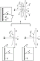
This will be described below with reference to fig. 5A to 5C. Fig. 5A is a diagram for explaining visual representation of a display image of the lighting device 1X according to the comparative example 1. Fig. 5B is a diagram for explaining visual representation of a display image of the lighting device 1Y according to the comparative example 2. Fig. 5C is a diagram for explaining visual representation of a display image of the illumination device 1 according to the embodiment.
In the illumination device 1X shown in fig. 5A, a general diffusion panel is used as the light control member. For example, in the illumination device 1X, the light control member 40 in the illumination device 1 shown in fig. 2 is a diffusion panel constituted only by the first diffusion layer 41.
In this case, when the image light is generated by the plurality of light emitting elements arranged in a two-dimensional shape, as shown in fig. 5A, the display image displayed on the diffusion panel is not blurred when viewed from a direction perpendicular to the light exit surface of the diffusion panel, but the display image displayed on the diffusion panel is blurred when viewed from a direction inclined with respect to the light exit surface of the diffusion panel. Specifically, the larger the angle formed by the line of sight of the user and the normal line of the diffusion panel, the more blurred the display image.
Therefore, as in the illumination device 1Y shown in fig. 5B, it is conceivable to use a diffusion panel having a haze smaller than that of the diffusion panel of the illumination device 1X shown in fig. 5A. That is, it is considered to reduce the degree of diffusion of the diffusion panel.
However, when the degree of diffusion of the diffusion panel is reduced, a display image is not blurred in the case of viewing from a direction inclined with respect to the light exit surface of the diffusion panel, but a plurality of light emitting elements arranged two-dimensionally appear in a dot shape in the case of viewing from a direction perpendicular to the light exit surface of the diffusion panel. That is, the user feels the granular sensation of the plurality of light emitting elements through the diffusion panel.
In contrast, in the illumination device 1 of the present embodiment, the light control member 40 in which the second diffusion layer 42 is laminated on the first diffusion layer 41 is used. Therefore, as shown in fig. 5C, when viewed from a direction perpendicular to the light exit surface of the light control member 40 or when viewed from a direction inclined with respect to the light exit surface of the light control member 40, the plurality of light emitting elements 22 arranged two-dimensionally do not appear in a dot shape, and the display image displayed on the light control member 40 does not blur. That is, the angular dependence of the blur of the display image can be reduced.
As described above, according to the illumination device 1 of the present embodiment, the light control member 40 that transmits light emitted from the plurality of light emitting elements 22 arranged in a two-dimensional shape includes the first diffusion layer 41 in which the haze in the vertical direction is smaller than the haze in the oblique direction and the second diffusion layer 42 in which the haze in the vertical direction is larger than the haze in the oblique direction.
With this configuration, it is possible to realize an illumination device capable of reflecting a display image with little change in the degree of blur of the illumination device 1 when viewed from a vertical direction or an oblique direction. For example, the user can view the display image of the sky and the clouds well regardless of whether the user views the lighting device 1 provided on the ceiling 2 from directly below or from a distance. This gives the user a feeling of a distant sky (depth feeling) like the actual sky. That is, although the display image is reflected on the lighting device 1, the user can feel as if the user were looking through the window from the inside without any strange feeling.
(modification example)
The lighting device according to the present invention has been described above based on the embodiments, but the present invention is not limited to the above embodiments.
For example, in the above-described embodiment, as shown in fig. 4, the haze of the light control member 40 in the range where the exit angle θ is-90 ° < θ <90 ° is fixed, but is not limited thereto.
Specifically, as shown in fig. 6, the haze of the light control member 40 in the oblique direction may be slightly reduced. In this case, when the haze in the inclined direction of the first diffusion layer 41 and the second diffusion layer 42 is slightly small or the haze in the perpendicular direction of the first diffusion layer 41 and the second diffusion layer 42 is slightly large, the haze in the inclined direction of the light control member 40 is slightly small.
As shown in fig. 7, the haze of the light control member 40 in the oblique direction may be slightly increased. In this case, when the haze in the inclined direction of the first diffusion layer 41 and the second diffusion layer 42 is large or the haze in the perpendicular direction of the first diffusion layer 41 and the second diffusion layer 42 is small, the haze in the inclined direction of the light control member 40 is slightly increased.
In addition, when the lighting device 1 is installed on the ceiling 2, if the angle formed by the normal line of the light emitting surface of the light control member 40 and the line of sight of the user exceeds 70 °, the user cannot visually recognize the display image reflected on the light emitting surface of the light control member 40 as a video image. Therefore, the haze of the light control member 40 may be substantially constant in a range where an angle formed by a normal line of the light exit surface of the light control member 40 and the line of sight of the user is 70 ° or less. Therefore, as shown in fig. 8, the haze of the light-controlling member 40 in the range where the exit angle θ is-70 ° ≦ θ ≦ 70 ° with respect to the light exit surface of the light-controlling member 40 may vary depending on the exit angle θ as long as the haze of the light-controlling member 40 is substantially constant in the range where the exit angle θ is-70 ° ≦ θ ≦ 70 °. For example, in fig. 8, in the range where the exit angle θ is θ < -70 °, 70 ° < θ, the haze is larger as the exit angle θ is larger. In this case, as the second diffusion layer 42, for example, a diffusion layer in which the haze in the oblique direction in the range where the exit angle θ is θ < -70 °, 70 ° < θ becomes very large as the exit angle θ becomes larger is used.
In addition, in the above embodiment, the first diffusion layer 41 and the second diffusion layer 42 are disposed so that the first diffusion layer 41 is on the inner side (the light emitting module 20 side) and the second diffusion layer 42 is on the outer side, but the present invention is not limited thereto. For example, the first diffusion layer 41 and the second diffusion layer 42 may be disposed on the inner side of the second diffusion layer 42 and on the outer side of the first diffusion layer 41.
In the above embodiment, the first diffusion layer 41 and the second diffusion layer 42 are each constituted by a diffusion plate, and are independent from each other. For example, the first diffusion layer 41 and the second diffusion layer 42 may be integrally formed as one diffusion plate. For example, the first diffusion layer 41 may be formed as a diffusion plate, and the second diffusion layer 42 may be formed as a surface layer of the diffusion plate. In this case, the second diffusion layer 42 can be formed by performing diffusion processing on the diffusion plate to form a diffusion structure.
In the above embodiment, the light control member 40 is constituted only by the first diffusion layer 41 and the second diffusion layer 42, but is not limited thereto. For example, the light control member 40 may have a third layer such as a transparent substrate that supports the first diffusion layer 41 and the second diffusion layer 42.
In the above embodiment, the lighting device 1 generates the image light from the images such as clouds by the plurality of light emitting elements 22 and displays the display image on the light control member 40, but the invention is not limited thereto. For example, illumination light having a difference in brightness may be generated by the plurality of light emitting elements 22, and a display image such as a pattern may be displayed on the light control member 40.
In the above embodiment, the case 10 has the frame 12, but is not limited thereto. For example, the frame 12 may be configured as a part of the ceiling 2 without providing the frame 12 in the casing 10.
In the above embodiment, the example in which the lighting device 1 is embedded in the ceiling 2 has been described, but the present invention is not limited thereto. For example, the lighting device 1 may be embedded in a building material such as a wall other than the ceiling 2.
In the above embodiment, the lighting device 1 includes the housing 10 and the light reflecting member 30, but is not limited thereto. That is, the lighting device 1 may not have the housing 10, or may not have the light reflecting member 30.
In the above embodiment, the lighting device 1 is configured such that the housing 10 and the light reflecting member 30 are disposed as separate members, but is not limited thereto. For example, the light reflecting member 30 may be formed integrally with the housing 10.
In the above-described embodiment, the example in which the control unit 50 controls the light emitting module 20 to reproduce the display image in accordance with the instruction of the user has been described, but the present invention is not limited thereto. For example, the control unit 50 may acquire the state of the sky from an imaging device (e.g., a camera or the like) that images the state of the sky, and reproduce a display image similar to the acquired state of the sky.
In the above-described embodiment, the example in which the control unit 50 reproduces the display image in accordance with the instruction of the user has been described, but the present invention is not limited to this. For example, the control unit 50 may have a timer function, acquire information on a video corresponding to a time when an instruction from the user is received from the storage unit, and control the light emitting module 20 based on the acquired information. Alternatively, the control unit 50 may acquire information related to the video from the storage unit when a predetermined time has elapsed, and control the light emitting module 20 based on the acquired information.