CN110550205B - Ornithopter steering control method, device and system - Google Patents
Ornithopter steering control method, device and system Download PDFInfo
- Publication number
- CN110550205B CN110550205B CN201910850560.9A CN201910850560A CN110550205B CN 110550205 B CN110550205 B CN 110550205B CN 201910850560 A CN201910850560 A CN 201910850560A CN 110550205 B CN110550205 B CN 110550205B
- Authority
- CN
- China
- Prior art keywords
- ornithopter
- wing
- outer section
- steering
- steering control
- Prior art date
- Legal status (The legal status is an assumption and is not a legal conclusion. Google has not performed a legal analysis and makes no representation as to the accuracy of the status listed.)
- Active
Links
Images




Classifications
-
- B—PERFORMING OPERATIONS; TRANSPORTING
- B64—AIRCRAFT; AVIATION; COSMONAUTICS
- B64C—AEROPLANES; HELICOPTERS
- B64C33/00—Ornithopters
- B64C33/02—Wings; Actuating mechanisms therefor
Landscapes
- Engineering & Computer Science (AREA)
- Aviation & Aerospace Engineering (AREA)
- Toys (AREA)
Abstract
The application provides a method, a device and a system for controlling the steering of a flapping-wing aircraft, wherein the method comprises the following steps: differential control is carried out on the incidence angles of the outer sections of the left side and the right side of the ornithopter so as to control the ornithopter to roll; when the incidence angle of the left outer section wing is positive and the incidence angle of the right outer section wing is negative, controlling the ornithopter to roll left; and when the incidence angle of the left outer section wing is negative and the incidence angle of the right outer section wing is positive, controlling the flapping wing aircraft to roll rightwards. The control of the course and the rolling of the ornithopter is realized, the operation process is simple, and the flexibility of controlling the steering is improved.
Description
Technical Field
The application relates to the technical field of intelligent control, in particular to a steering control method, device and system of a ornithopter.
Background
The ornithopter is an aircraft which simulates a natural bird by generating lift force and thrust through flapping wings, and has the advantages which are incomparable with straight-wing aircraft, helicopters and other types of aircraft. For example, the flapping-wing aircraft adopting the oscillating wing and the flapping-wing aircraft adopting the flat-moving wing are both driven by a machine, and the mechanical drive has the adjustability far lower than the muscular tissue of birds, and the flight stability is poor.
In the prior art, the flapping-wing aircraft adopts course control, specifically, a single chip microcomputer can receive three position signals of a rudder through a micro switch; when the rudder is in the neutral position, the aircraft course is not changed; when the rudder is pedaled leftwards, the airplane turns leftwards; when the aircraft is pedaled to the right, the aircraft turns to the right. However, this control method needs a complex circuit for support, and if it needs to be improved, it has poor flexibility and is difficult to implement.
Disclosure of Invention
The application provides a steering control method, a device and a system of a ornithopter, which aim to overcome the defects of poor flexibility and the like in the prior art.
A first aspect of the present application provides a steering control method of an ornithopter, comprising:
differential control is carried out on the incidence angles of the outer sections of the left side and the right side of the ornithopter so as to control the ornithopter to roll;
when the incidence angle of the left outer section wing is positive and the incidence angle of the right outer section wing is negative, controlling the ornithopter to roll left;
and when the incidence angle of the left outer section wing is negative and the incidence angle of the right outer section wing is positive, controlling the flapping wing aircraft to roll rightwards.
Optionally, the differential control of the attack angles of the left and right outer wings of the ornithopter comprises:
and respectively controlling the left and right outer section wing ribs to rotate around the outer section wing main shaft so as to control the attack angles of the left and right outer section wings.
Optionally, said separately controlling the left and right outer panel wing ribs to rotate about the outer panel wing main axis comprises:
and respectively controlling the left outer section wing rib and the right outer section wing rib to rotate around the outer section wing main shaft by adopting an actuating mechanism.
Optionally, the actuating mechanism comprises a steering engine and a connecting assembly, and the steering engine is connected with the left or right outer wing rib through the connecting assembly.
A second aspect of the present application provides a steering control apparatus of an ornithopter, comprising:
the actuator comprises a steering engine and a connecting component, the steering engine is connected with the connecting component, the connecting component is connected with outer wing ribs of the wings of the ornithopter, the steering engine controls the outer wing ribs to rotate around an outer wing main shaft through the connecting component so as to control the attack angles of the left outer wing and the right outer wing,
when the incidence angle of the left outer section wing is positive and the incidence angle of the right outer section wing is negative, controlling the ornithopter to roll left;
and when the incidence angle of the left outer section wing is negative and the incidence angle of the right outer section wing is positive, controlling the flapping wing aircraft to roll rightwards.
Optionally, the connecting assembly is a four-bar linkage.
Optionally, the connecting assembly is sleeved outside the outer section wing main shaft through a bearing.
A third aspect of the present application provides a steering control system of an ornithopter, comprising:
the flight control device is connected with the steering control device of the ornithopter, and the steering control device of the ornithopter is respectively connected with the left outer section wing of the ornithopter and the right outer section wing of the ornithopter;
the flight control device is used for providing a rotation signal for a steering control device of the ornithopter;
and the steering control device of the ornithopter controls the left and right outer section wing ribs to rotate around the outer section wing main shaft according to the rotation signal so as to control the attack angles of the left and right outer section wings.
Optionally, the ornithopter steering control system comprises one ornithopter steering control device connected to the left or right outer panel rib.
Optionally, the steering control system of the ornithopter comprises two steering control devices of the ornithopter, and the two steering control devices of the ornithopter are respectively connected with the left outer wing rib and the right outer wing rib of the ornithopter.
According to the method, the device and the system for controlling the steering of the ornithopter, the incidence angles of the outer sections of the left side and the right side of the ornithopter are differentially controlled to control the ornithopter to roll; when the incidence angle of the left outer section wing is positive and the incidence angle of the right outer section wing is negative, controlling the ornithopter to roll left; when the incidence angle of the left outer section wing is negative and the incidence angle of the right outer section wing is positive, the right rolling of the ornithopter is controlled, the heading and the rolling of the ornithopter are controlled, the operation process is simple, and the flexibility of steering control is improved.
Drawings
In order to more clearly illustrate the embodiments of the present application or the technical solutions in the prior art, the drawings needed to be used in the description of the embodiments or the prior art will be briefly introduced below, and it is obvious that the drawings in the following description are some embodiments of the present application, and for those skilled in the art, other drawings can be obtained according to these drawings without inventive exercise.
FIG. 1 is a schematic flow chart of a steering control method for an ornithopter according to an embodiment of the present invention;
FIG. 2 is a schematic structural diagram of a steering control device of an ornithopter according to an embodiment of the present disclosure;
FIG. 3 is a schematic structural diagram of a steering control device of an ornithopter according to another embodiment of the present application;
FIG. 4 is a schematic diagram of a four bar linkage configuration of an ornithopter according to an embodiment of the present disclosure;
FIG. 5A is a schematic structural diagram illustrating a state of a four-bar linkage according to an embodiment of the present disclosure;
FIG. 5B is a schematic structural diagram illustrating another state of a four-bar linkage according to an embodiment of the present disclosure;
FIG. 5C is a schematic structural diagram illustrating another state of a four-bar linkage according to an embodiment of the present disclosure;
FIG. 6 is a schematic structural diagram of a steering control system of an ornithopter according to an embodiment of the present application;
FIG. 7A is a schematic view of the attitude of a ornithopter according to an embodiment of the present disclosure, when the left and right outer wing angles of attack are 0;
FIG. 7B is a schematic view of an attitude of an ornithopter according to an embodiment of the present disclosure when the left outer wing angle of attack is negative and the right outer wing angle of attack is positive;
fig. 7C is a schematic view of a posture when the left outer blade angle of attack is positive and the right outer blade angle of attack is negative of the ornithopter according to the embodiment of the present application;
fig. 8A is a schematic view of an attack angle b of an outer blade being 0 according to an embodiment of the present application;
FIG. 8B is a schematic view of an outer wing with a positive angle of attack according to an embodiment of the present application;
fig. 8C is a schematic view of an outer wing angle of attack being negative according to an embodiment of the present application.
With the above figures, there are shown specific embodiments of the present application, which will be described in more detail below. These drawings and written description are not intended to limit the scope of the disclosed concepts in any way, but rather to illustrate the concepts of the disclosure to those skilled in the art by reference to specific embodiments.
Detailed Description
In order to make the objects, technical solutions and advantages of the embodiments of the present application clearer, the technical solutions in the embodiments of the present application will be clearly and completely described below with reference to the drawings in the embodiments of the present application, and it is obvious that the described embodiments are some embodiments of the present application, but not all embodiments. All other embodiments, which can be derived by a person skilled in the art from the embodiments given herein without making any creative effort, shall fall within the protection scope of the present application.
The following several specific embodiments may be combined with each other, and details of the same or similar concepts or processes may not be repeated in some embodiments. Embodiments of the present invention will be described below with reference to the accompanying drawings.
An embodiment of the application provides a steering control method of a ornithopter, which is used for steering control of the ornithopter.
As shown in fig. 1, a schematic flow chart of a steering control method of an ornithopter provided in this embodiment is provided, where the method includes:
102, controlling the ornithopter to roll left when the incidence angle of the left outer section wing is positive and the incidence angle of the right outer section wing is negative; and when the incidence angle of the left outer section wing is negative and the incidence angle of the right outer section wing is positive, controlling the flapping wing aircraft to roll rightwards.
Specifically, the left side wing and the right side wing of the ornithopter are both provided with two sections of wings, each wing comprises a main wing and an outer section wing, the rolling control of the ornithopter is realized by utilizing the differential control of the attack angle (or called attack angle) of the outer section wings on the left side and the right side of the ornithopter, and the turning control method of the ornithopter is different from the roll control of the ailerons of the traditional fixed wings in that when the attack angle of the outer section wing on the left side is positive and the attack angle of the outer section wing on the right side is negative, the ornithopter is controlled to roll leftwards; and when the incidence angle of the left outer section wing is negative and the incidence angle of the right outer section wing is positive, controlling the flapping wing aircraft to roll rightwards.
The right angle of attack of the left outer wing means that the left outer wing rib rotates around the outer wing main shaft, so that the left outer wing deflects downwards (or is called downwards pressing) relative to the outer wing main shaft.
The negative attack angle of the left outer wing means that the left outer wing rib turns around the outer wing main shaft, so that the left outer wing is inclined upward (or tilted upward) relative to the outer wing main shaft.
The right outer wing attack angle is positive, which means that the right outer wing rib overturns around the outer wing main shaft, so that the right outer wing is deflected downwards relative to the outer wing main shaft.
The negative angle of attack of the right outer wing means that the rib of the right outer wing turns around the main shaft of the outer wing, so that the right outer wing is inclined upwards relative to the main shaft of the outer wing.
Alternatively, the outboard rib on each side may be rotated about the outboard mast by an actuator.
Optionally, the differential control of the attack angle of the outer blade may also be implemented by other devices, which is not limited in this embodiment. As long as the differential control of the attack angle of the outer section of the wing can be realized, the roll control of the ornithopter can be realized, the lift force and the thrust balance of the left wing and the right wing can be changed, and the steering is opposite to the steering caused by the differential control mode of the fixed wing aileron. The steering resulting from the fixed-wing aileron differential control is: when the left aileron of the fixed wing deflects downwards and the right aileron deflects upwards, the ornithopter turns rightwards; when the left aileron of the fixed wing deflects upwards and the right aileron deflects downwards, the ornithopter turns left.
According to the steering control method of the ornithopter, the incidence angles of the outer sections of the left side and the right side of the ornithopter are differentially controlled to control the ornithopter to roll; when the incidence angle of the left outer section wing is positive and the incidence angle of the right outer section wing is negative, controlling the ornithopter to roll left; when the incidence angle of the left outer section wing is negative and the incidence angle of the right outer section wing is positive, the right rolling of the ornithopter is controlled, the heading and the rolling of the ornithopter are controlled, the operation process is simple, and the flexibility of steering control is improved.
The present application further provides a supplementary explanation of the steering control method of an ornithopter provided in the above embodiments.
As a practical way, on the basis of the above embodiments, the differential control of the attack angles of the left and right outer wings of the ornithopter comprises:
and respectively controlling the left and right outer section wing ribs to rotate around the outer section wing main shaft so as to control the attack angles of the left and right outer section wings.
Specifically, the left outer wing rib is controlled to rotate around the left outer wing main shaft to control the angle of attack of the left outer wing, and the right outer wing rib is controlled to rotate around the right outer wing main shaft to control the angle of attack of the right outer wing.
Alternatively, an actuator may be employed to control rotation of the left outboard wing rib about the left outboard wing main axis and to control rotation of the right outboard wing rib about the right outboard wing main axis.
Optionally, the actuating mechanism may include a steering engine and a connecting assembly, wherein the steering engine is connected to the left or right outer wing rib through the connecting assembly, so as to control the outer wings on each side to rotate around the main shaft of the outer wing, thereby controlling the attack angle of the outer wings.
The steering wheel can be including output steering wheel, reduction gear group, position feedback potentiometer, direct current motor and control circuit board, wherein, control circuit board with direct current motor connects, reduction gear group respectively with direct current motor with the output steering wheel is connected, the position feedback potentiometer respectively with the output steering wheel with the circuit board is connected.
The steering engine can acquire a control signal sent by the flight control device of the ornithopter. Specifically, a control circuit board in the steering engine receives a control signal sent by a flight control device and controls a direct current motor to rotate, the direct current motor drives a reduction gear set to rotate, and the direct current motor is driven to an output steering wheel after being reduced. The output shaft of the steering engine is connected with the position feedback potentiometer, the position feedback potentiometer is driven while the output steering wheel rotates, the position feedback potentiometer outputs a voltage signal to the control circuit board for feedback, and then the control circuit board determines the rotation direction and speed of the direct current motor according to the position of the pointer of the position feedback potentiometer.
For example, the control signal received by the steering engine is a pulse signal (hereinafter referred to as an input pulse) having a cycle of about 20 milliseconds and a width of 1 millisecond to 2 milliseconds. When the steering engine receives the control signal, a negative standard middle pulse signal (which can be called a standard pulse) which is the same as the control signal and has the width of 1.5 milliseconds is excited immediately. The input pulse and the standard pulse are added in an adder to obtain a difference pulse. If the input pulse is wider than the negative standard pulse, the obtained pulse is a positive difference pulse. If the input pulse is narrower than the standard pulse, the addition will result in a positive negative difference pulse. The amplified difference pulse is the power signal for driving the steering engine to rotate forwards and backwards. The rotation of the direct current motor of the steering engine is decelerated by the reduction gear set, the steering wheel and the position feedback potentiometer are driven to rotate at the same time, and the rotation cannot be stopped until the standard pulse and the input pulse are completely the same in width and the difference pulse disappears.
Position feedback potentiometer is also position detector (angle sensor), is the input sensor of steering wheel, and steering wheel pivoted position change, position detector's resistance value will follow and change. The control circuit of the control circuit board reads the resistance value, so that the speed and the direction of the motor can be properly adjusted according to the resistance value, and the motor rotates to a specified angle. Thereby realizing the control of the accurate rotation of the steering engine.
The steering engine controls the outer section wing to rotate around the outer section wing main shaft through the connecting component, and the control of the attack angle of the outer section wing is achieved.
Alternatively, the connection assembly may be a four bar linkage or other type of connection.
Alternatively, a hydraulic control system may be used to control the angle of attack of the outer blade.
Alternatively, the control of the outer wing attack angle may also be achieved by a servo control system.
According to the steering control method of the ornithopter, the incidence angles of the outer sections of the left side and the right side of the ornithopter are differentially controlled to control the ornithopter to roll; when the incidence angle of the left outer section wing is positive and the incidence angle of the right outer section wing is negative, controlling the ornithopter to roll left; when the incidence angle of the left outer section wing is negative and the incidence angle of the right outer section wing is positive, the right rolling of the ornithopter is controlled, the heading and the rolling of the ornithopter are controlled, the operation process is simple, and the flexibility of steering control is improved.
In another embodiment of the present application, a steering control apparatus for a ornithopter is provided.
Fig. 2 is a schematic structural diagram of a steering control device of an ornithopter according to the present embodiment. The steering control device of the ornithopter comprises: the flapping wing aircraft comprises a steering engine 1 and a connecting assembly 2, wherein the steering engine 1 is connected with the connecting assembly 2, the connecting assembly 2 is connected with an outer wing rib 3 of a flapping wing aircraft wing, and the steering engine 1 controls the outer wing rib 3 to rotate around an outer wing main shaft to control the angle of attack of the outer wing through the connecting assembly.
Specifically, the steering control device of the ornithopter is arranged on the outer section wing on the left side or the right side of the ornithopter and connected with the outer section wing rib, the outer section wing rib is controlled to rotate around the outer section wing main shaft, so that the attack angle of the outer section wing is controlled, and the rolling control of the ornithopter is realized through the differential control of the attack angles of the outer section wing on the left side and the right side of the ornithopter.
When the incidence angle of the left outer section wing is positive and the incidence angle of the right outer section wing is negative, controlling the ornithopter to roll left;
and when the incidence angle of the left outer section wing is negative and the incidence angle of the right outer section wing is positive, controlling the flapping wing aircraft to roll rightwards.
Specifically, the steering engine can include output steering wheel, reduction gear group, position feedback potentiometer, direct current motor and control circuit board, wherein, control circuit board with direct current motor connects, reduction gear group respectively with direct current motor with the output steering wheel is connected, position feedback potentiometer respectively with the output steering wheel with the circuit board is connected.
The steering engine can acquire a control signal sent by the flight control device of the ornithopter. Specifically, a control circuit board in the steering engine receives a control signal sent by a flight control device and controls a direct current motor to rotate, the direct current motor drives a reduction gear set to rotate, and the direct current motor is driven to an output steering wheel after being reduced. The output shaft of the steering engine is connected with the position feedback potentiometer, the position feedback potentiometer is driven while the output steering wheel rotates, the position feedback potentiometer outputs a voltage signal to the control circuit board for feedback, and then the control circuit board determines the rotation direction and speed of the direct current motor according to the position of the pointer of the position feedback potentiometer.
The control circuit board and the flight control device are electrically connected, and can be in wired connection or wireless connection.
For example, the control signal received by the steering engine is a pulse signal (hereinafter referred to as an input pulse) having a cycle of about 20 milliseconds and a width of 1 millisecond to 2 milliseconds. When the steering engine receives the control signal, a negative standard middle pulse signal (which can be called a standard pulse) which is the same as the control signal and has the width of 1.5 milliseconds is excited immediately. The input pulse and the standard pulse are added in an adder to obtain a difference pulse. If the input pulse is wider than the negative standard pulse, the obtained pulse is a positive difference pulse. If the input pulse is narrower than the standard pulse, the addition will result in a positive negative difference pulse. The amplified difference pulse is the power signal for driving the steering engine to rotate forwards and backwards. The rotation of the direct current motor of the steering engine is decelerated by the reduction gear set, the steering wheel and the position feedback potentiometer are driven to rotate at the same time, and the rotation cannot be stopped until the standard pulse and the input pulse are completely the same in width and the difference pulse disappears.
Position feedback potentiometer is also position detector (angle sensor), is the input sensor of steering wheel, and steering wheel pivoted position change, position detector's resistance value will follow and change. The control circuit of the control circuit board reads the resistance value, so that the speed and the direction of the motor can be properly adjusted according to the resistance value, and the motor rotates to a specified angle. Thereby realizing the control of the accurate rotation of the steering engine.
The steering engine controls the outer section wing to rotate around the outer section wing main shaft through the connecting component, and the control of the attack angle of the outer section wing is achieved.
The steering control device of the ornithopter provided by the embodiment controls the ornithopter to roll by performing differential control on the incidence angles of the outer sections of the left side and the right side of the ornithopter; when the incidence angle of the left outer section wing is positive and the incidence angle of the right outer section wing is negative, controlling the ornithopter to roll left; when the incidence angle of the left outer section wing is negative and the incidence angle of the right outer section wing is positive, the right rolling of the ornithopter is controlled, the heading and the rolling of the ornithopter are controlled, the operation process is simple, and the flexibility of steering control is improved.
The present application further provides a supplementary explanation of the steering control device of an ornithopter according to the above-described embodiment.
Fig. 3 is a schematic structural diagram of a steering control device of an ornithopter according to this embodiment. The steering control device includes at least: steering wheel 1 and coupling assembling 2, steering wheel 1 with coupling assembling 2 connects, coupling assembling 2 and outer section wing rib 3 are connected, steering wheel 1 passes through coupling assembling 2 control outer section wing rib 3 rotates around outer section wing main shaft to it is rotatory around outer section wing main shaft to drive outer section wing, thereby control the angle of attack of outer section wing.
Specifically, steering wheel 1 fixed connection is on the mounting panel, and the rotation signal that receives flap aircraft flight control device and send is received, and according to rotation signal control steering wheel direct current motor produces the rotation of certain angle, drives outer section wing rib rotatory certain angle through coupling assembling 2, and outer section wing rib rotates around outer section wing main shaft, and then drives the outer section wing and carries out the rotation of certain angle to the angle of attack of adjustment outer section wing.
It should be noted that the steering wheel can drive the relative horizontal plane of outer section wing and rotate certain angle, can set up according to actual demand.
The ornithopter steering control device provided by the embodiment of the application has the advantages that the ornithopter steering control device is additionally arranged on the ornithopter outer-section wing part, the outer-section wing ribs of the ornithopter are controlled to drive the outer-section wing to rotate around the main shaft of the outer-section wing, so that the heading and rolling hybrid control of the ornithopter is realized, the operation process is simple, and the flexibility of steering control is improved.
Optionally, the connecting assembly is a four-bar linkage.
Optionally, the connecting assembly is mainly used for transmission, and may be a connecting rod assembly, or may be a belt, a chain, a gear, etc. as a transmission device, for example, the connecting rod assembly may be a three-connecting rod, a four-connecting rod, a five-connecting rod, etc., in this embodiment of the present application, it is preferable that the connecting assembly of a four-connecting rod structure is adopted, and since the four-connecting rod structure can make the rods on the left and right sides rotate in the same amplitude, the rotation of the main rod is transmitted to the auxiliary rod in the same amplitude.
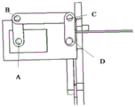
Specifically, as shown in fig. 4, a schematic diagram of a four-bar linkage structure of the ornithopter provided in this embodiment is shown, wherein a basic type of the planar four-bar linkage structure is a hinged four-bar linkage structure, an AD bar is a frame, an AB bar and a CD bar connected to the frame are called side links, a BC bar opposite to the frame is called a linkage, a side link capable of performing a full-circle rotation motion is a crank, and a side link capable of only swinging within a certain range is a rocker.
As shown in fig. 5A, a structural diagram of a state of the four-bar linkage structure provided in this embodiment is shown, in which an attack angle of the outer wing is 0; as shown in fig. 5B, another structural diagram of the four-bar linkage structure provided in this embodiment is shown, in which the attack angle of the outer wing is positive; as shown in fig. 5C, a structural diagram of another state of the four-bar linkage structure provided in this embodiment is shown, in which the attack angle of the outer blade is negative. As shown in fig. 5A, point a is the output shaft of the steering engine, point D is the main shaft of the aileron, point B, point C are the other two endpoints of the four-bar linkage, because point a and point D are fixed on the mounting panel, which is equivalent to the AD rod in the four-bar linkage, i.e., the frame, the other three rods are the AB rod, the BC rod and the CD rod, the AB rod and the CD rod connected with the frame are called the link rods, the BC rod opposite to the frame is called the link rod, the link rod AB rod capable of making the full-circle rotary motion is the crank, the link rod CD rod capable of only swinging within a certain range is the rocker, and the CD rod rotates following the rotation of the AB rod.
The planar four-bar linkage is suitable for transmitting larger power, can realize various motion track curves and operation rules, can be used for directly completing an actuating mechanism with certain track requirements, depends on mutual contact among geometric profile musty eating members of kinematic pair elements, is easy to manufacture, can easily ensure required manufacturing precision, and can realize a remote transmission control mechanism.
Optionally, the connecting assembly is sleeved outside the aileron main shaft through a bearing.
On the basis of the above embodiment, as can be seen from fig. 3 and 5A, the output shaft of the steering engine is fixedly connected with one end of the AD rod of the four-link connecting assembly, the AB rod is connected with the BC rod through a bearing, one end of the BC rod is connected with one end of the CD rod through a bearing, the other end of the CD rod of the four-link connecting assembly is fixedly connected with the outer wing rib, one end fixedly connected with the outer wing rib is connected to the outer side of the outer wing main shaft, and the four-link connecting assembly can rotate around the outer wing main shaft.
It should be noted that one end of the connecting assembly fixedly connected to the outer wing rib may be externally connected to the outer side of the outer wing main shaft in any connection manner, and preferably, may be sleeved on the outer side of the outer wing main shaft by a bearing.
For example, the D end of the CD rod of the four-bar linkage is fixedly connected to the outer wing rib, and a hole is provided at the D end, through which the outer wing spindle is connected to the four-bar linkage by a bearing, and the CD rod is sleeved outside the aileron spindle by a bearing.
In the actual rotation process, the steering engine receives the rotation signal that ornithopter flight control device sent, the output shaft of steering engine produces the rotation of certain angle, AB pole through driving the four-bar linkage rotates, AB pole drives the operation of BC pole, and then drives the CD pole motion, the outer section wing rib that is connected with the CD pole moves thereupon, outer section wing rib rotates around outer section wing main shaft promptly, make the outer section wing produce the rotation of certain angle, thereby make the angle of attack of outer section wing take place certain angular variation.
As shown in fig. 3, the outer wing rib 3, the outer wing main shaft 4 and the extension portion 5 are connected to form a complete outer wing, and the outer wing is driven to rotate around the outer wing main shaft by the rotation of the outer wing rib 3.
Optionally, the outer panel wing rib is perpendicular to the outer panel wing main axis.
On the basis of the embodiment, the output shaft of the steering engine is fixedly connected with one end of an AD rod of a four-connecting-rod connecting assembly, an AB rod is connected with a BC rod through a bearing, one end of the BC rod is connected with one end of a CD rod of the four-connecting-rod connecting assembly through a bearing, the other end of the CD rod of the four-connecting-rod connecting assembly is fixedly connected with an outer section wing rib, and one end of the CD rod fixedly connected with the outer section wing rib is sleeved outside the outer section wing main shaft through a bearing.
The steering control device of the ornithopter provided by the embodiment controls the ornithopter to roll by performing differential control on the incidence angles of the outer sections of the left side and the right side of the ornithopter; when the incidence angle of the left outer section wing is positive and the incidence angle of the right outer section wing is negative, controlling the ornithopter to roll left; when the incidence angle of the left outer section wing is negative and the incidence angle of the right outer section wing is positive, the right rolling of the ornithopter is controlled, the heading and the rolling of the ornithopter are controlled, the operation process is simple, and the flexibility of steering control is improved.
In another embodiment of the present application, a steering control system for an ornithopter is provided.
Fig. 6 is a schematic structural diagram of a steering control system of the ornithopter according to the present embodiment. The steering control system of the ornithopter comprises: the flight control device is connected with the steering control device of the ornithopter, and the steering control device of the ornithopter is connected with the outer section wing;
the flight control device is used for providing a rotation signal for a steering control device of the ornithopter;
and the steering control device of the ornithopter controls the wing ribs of the outer section wing to rotate around the outer section wing main shaft according to the rotation signal so as to drive the outer section wing to rotate, thereby controlling the attack angle of the outer section wing.
Optionally, the steering control system of the ornithopter may include one steering control device of the ornithopter, and may also include two steering control devices of the ornithopter, which may be specifically set according to actual requirements.
Specifically, if the ornithopter comprises a steering control device of the ornithopter, the steering control device of the ornithopter can be connected with the left or right outer section wing, and the roll of the ornithopter is controlled by controlling the attack angle of the outer section wing on one side.
If the flapping-wing aircraft comprises two steering control devices of the flapping-wing aircraft, the steering control devices of the two flapping-wing aircraft are respectively connected with the left outer section wing and the right outer section wing, and the roll of the flapping-wing aircraft is controlled by controlling the attack angles of the two outer section wings.
For example, as shown in fig. 7A, the schematic attitude diagram of the ornithopter provided in the present embodiment when the left and right outer wing attack angles are 0. As shown in fig. 7B, the attitude schematic diagram of the ornithopter provided in this embodiment when the left outer blade angle of attack is negative and the right outer blade angle of attack is positive. As shown in fig. 7C, the attitude schematic diagram of the ornithopter provided in this embodiment when the left outer blade angle of attack is positive and the right outer blade angle of attack is negative. With reference to fig. 5A to 5C, when the steering engine in the steering control device of the ornithopter is in the neutral position, the attack angle of the outer wing of the ornithopter is 0, and the ornithopter flies straight when the ornithopter is in the horizontal position; when a steering engine in a steering control device of the ornithopter deflects, an outer section wing of the ornithopter is driven to rotate, and if the attack angle of the left outer section wing is negative and the attack angle of the right outer section wing is positive, the ornithopter is controlled to roll rightwards; when the steering engine deflects, if the incidence angle of the left outer section wing is positive and the incidence angle of the right outer section wing is negative, the ornithopter is controlled to roll left.
As shown in fig. 8A, an attack angle diagram of the outer blade attack angle b of 0 is provided for the present embodiment. As shown in fig. 8B, the attack angle of the outer blade provided for this embodiment is a positive attack angle schematic diagram. As shown in fig. 8C, the attack angle of the outer blade provided for this embodiment is a negative attack angle schematic diagram. Wherein, the broken line represents an attack angle reference line, the main shaft 4 of the outer section wing is vertical to the paper,
specifically, when the left outer wing section deflects below the horizontal position and the right outer wing section deflects above the horizontal position, the ornithopter turns left as shown in fig. 7C; when the left outer section wing deflects above horizontal and the right outer section wing deflects below horizontal, the ornithopter turns right as shown in fig. 7B.
The application provides a steering control system of ornithopter, through increase the steering control device at ornithopter outer wing part, the outer wing of control ornithopter can rotate around the main shaft of outer wing, and then has realized the hybrid control of the course of ornithopter and roll, and operation process is simple to the flexibility that the improvement control turned to.
It should be noted that, the specific control manner of the steering control system of the ornithopter provided in this embodiment has been described in detail in the embodiments of the method and the apparatus, and the detailed description of this embodiment is omitted.
The steering control system of the ornithopter provided by the embodiment controls the ornithopter to roll by performing differential control on the incidence angles of the left outer section wing and the right outer section wing of the ornithopter; when the incidence angle of the left outer section wing is positive and the incidence angle of the right outer section wing is negative, controlling the ornithopter to roll left; when the incidence angle of the left outer section wing is negative and the incidence angle of the right outer section wing is positive, the right rolling of the ornithopter is controlled, the heading and the rolling of the ornithopter are controlled, the operation process is simple, and the flexibility of steering control is improved.
Other embodiments of the disclosure will be apparent to those skilled in the art from consideration of the specification and practice of the disclosure disclosed herein. This application is intended to cover any variations, uses, or adaptations of the disclosure following, in general, the principles of the disclosure and including such departures from the present disclosure as come within known or customary practice within the art to which the disclosure pertains. It is intended that the specification and examples be considered as exemplary only, with a true scope and spirit of the disclosure being indicated by the following claims.
It will be understood that the present disclosure is not limited to the precise arrangements described above and shown in the drawings and that various modifications and changes may be made without departing from the scope thereof. The scope of the present disclosure is limited only by the appended claims.
Finally, it should be noted that: the above embodiments are only used for illustrating the technical solutions of the present application, and not for limiting the same; although the present application has been described in detail with reference to the foregoing embodiments, it should be understood by those of ordinary skill in the art that: the technical solutions described in the foregoing embodiments may still be modified, or some or all of the technical features may be equivalently replaced; and the modifications or the substitutions do not make the essence of the corresponding technical solutions depart from the scope of the technical solutions of the embodiments of the present application.
Claims (10)
1. A method for controlling the steering of an ornithopter, comprising:
differential control is carried out on the incidence angles of the outer sections of the left side and the right side of the ornithopter so as to control the ornithopter to roll;
when the incidence angle of the left outer section wing is positive and the incidence angle of the right outer section wing is negative, controlling the ornithopter to roll left;
and when the incidence angle of the left outer section wing is negative and the incidence angle of the right outer section wing is positive, controlling the flapping wing aircraft to roll rightwards.
2. The method of claim 1, wherein the differentially controlling the left and right outboard wing angles of attack of the ornithopter comprises:
and respectively controlling the left and right outer section wing ribs to rotate around the outer section wing main shaft so as to control the attack angles of the left and right outer section wings.
3. The method of claim 2, wherein said separately controlling the left and right outer panel wing ribs to rotate about the outer panel wing main axis comprises:
and respectively controlling the left outer section wing rib and the right outer section wing rib to rotate around the outer section wing main shaft by adopting an actuating mechanism.
4. The method of claim 3, wherein the actuator comprises a steering engine and a connecting assembly, and the steering engine is connected with the left or right outer section wing rib through the connecting assembly.
5. A steering control device for an ornithopter, comprising:
the actuator comprises a steering engine and a connecting component, the steering engine is connected with the connecting component, the connecting component is connected with outer wing ribs of the wings of the ornithopter, the steering engine controls the outer wing ribs to rotate around an outer wing main shaft through the connecting component so as to control the attack angles of the left outer wing and the right outer wing,
when the incidence angle of the left outer section wing is positive and the incidence angle of the right outer section wing is negative, controlling the ornithopter to roll left;
and when the incidence angle of the left outer section wing is negative and the incidence angle of the right outer section wing is positive, controlling the flapping wing aircraft to roll rightwards.
6. The apparatus of claim 5, wherein the connection assembly is a four bar linkage.
7. The device of claim 5, wherein the connection assembly is sleeved outside the outer section wing main shaft through a bearing.
8. A steering control system for an ornithopter, comprising: a flight control device, a steering control device of the ornithopter as claimed in any one of claims 5 to 7, a left outer wing section of the ornithopter and a right outer wing section of the ornithopter, the flight control device being connected to the steering control device of the ornithopter, the steering control device of the ornithopter being connected to the left outer wing section of the ornithopter and the right outer wing section of the ornithopter, respectively;
the flight control device is used for providing a rotation signal for a steering control device of the ornithopter;
and the steering control device of the ornithopter controls the left and right outer section wing ribs to rotate around the outer section wing main shaft according to the rotation signal so as to control the attack angles of the left and right outer section wings.
9. The ornithopter steering control system of claim 8, wherein the ornithopter steering control system comprises one ornithopter steering control device, the one ornithopter steering control device being connected to either the left or right outboard rib.
10. The ornithopter steering control system according to claim 8, wherein the ornithopter steering control system comprises two ornithopter steering control devices, and the two ornithopter steering control devices are connected to the left outer wing rib and the right outer wing rib of the ornithopter, respectively.
Priority Applications (1)
| Application Number | Priority Date | Filing Date | Title |
|---|---|---|---|
| CN201910850560.9A CN110550205B (en) | 2019-09-10 | 2019-09-10 | Ornithopter steering control method, device and system |
Applications Claiming Priority (1)
| Application Number | Priority Date | Filing Date | Title |
|---|---|---|---|
| CN201910850560.9A CN110550205B (en) | 2019-09-10 | 2019-09-10 | Ornithopter steering control method, device and system |
Publications (2)
| Publication Number | Publication Date |
|---|---|
| CN110550205A CN110550205A (en) | 2019-12-10 |
| CN110550205B true CN110550205B (en) | 2020-11-06 |
Family
ID=68739748
Family Applications (1)
| Application Number | Title | Priority Date | Filing Date |
|---|---|---|---|
| CN201910850560.9A Active CN110550205B (en) | 2019-09-10 | 2019-09-10 | Ornithopter steering control method, device and system |
Country Status (1)
| Country | Link |
|---|---|
| CN (1) | CN110550205B (en) |
Families Citing this family (3)
| Publication number | Priority date | Publication date | Assignee | Title |
|---|---|---|---|---|
| CN113212749B (en) | 2021-07-08 | 2021-10-01 | 北京科技大学 | A bionic butterfly flapping aircraft and its pull-wire steering mechanism |
| CN116176836B (en) * | 2023-02-17 | 2024-07-19 | 北京科技大学 | Bionic ornithopter steering mechanism based on cambered surface wings |
| CN117446164A (en) * | 2023-08-09 | 2024-01-26 | 广东粤港澳大湾区黄埔材料研究院 | A steering control method and system for a steering gear-driven flapping-wing aircraft |
Citations (7)
| Publication number | Priority date | Publication date | Assignee | Title |
|---|---|---|---|---|
| CN101041382A (en) * | 2006-03-20 | 2007-09-26 | 西北工业大学 | Rolling control mechanism for minitype ornithopter |
| CN202609083U (en) * | 2012-05-25 | 2012-12-19 | 哈尔滨工业大学深圳研究生院 | Flapping wing structure of mini-sized flapping wing air vehicle and mini-sized flapping wing air vehicle |
| CN103241379A (en) * | 2013-05-16 | 2013-08-14 | 中国科学院长春光学精密机械与物理研究所 | Flapping wing device for achieving active torsion for flapping wings and wing planes of aerofoil |
| CN104260882A (en) * | 2014-09-04 | 2015-01-07 | 北京航空航天大学 | Active-twisting flapping wing and aircraft with active-twisting flapping wing |
| GB2520460A (en) * | 2012-09-17 | 2015-05-20 | Blue Bear Systems Res Ltd | Variable geometry wing |
| CN106585984A (en) * | 2017-01-03 | 2017-04-26 | 璋峰嘲 | Rolling and rotating ornithopter |
| CN107472528A (en) * | 2017-08-10 | 2017-12-15 | 北京航空航天大学 | What a kind of angle of attack was passively overturn flap flapping wing device and flight control method |
Family Cites Families (2)
| Publication number | Priority date | Publication date | Assignee | Title |
|---|---|---|---|---|
| KR100580962B1 (en) * | 2004-10-05 | 2006-05-16 | 장동영 | Newbot's winged drive |
| JP2012529398A (en) * | 2009-06-05 | 2012-11-22 | エアロバイロメント | Aircraft flight mechanism and control method |
-
2019
- 2019-09-10 CN CN201910850560.9A patent/CN110550205B/en active Active
Patent Citations (7)
| Publication number | Priority date | Publication date | Assignee | Title |
|---|---|---|---|---|
| CN101041382A (en) * | 2006-03-20 | 2007-09-26 | 西北工业大学 | Rolling control mechanism for minitype ornithopter |
| CN202609083U (en) * | 2012-05-25 | 2012-12-19 | 哈尔滨工业大学深圳研究生院 | Flapping wing structure of mini-sized flapping wing air vehicle and mini-sized flapping wing air vehicle |
| GB2520460A (en) * | 2012-09-17 | 2015-05-20 | Blue Bear Systems Res Ltd | Variable geometry wing |
| CN103241379A (en) * | 2013-05-16 | 2013-08-14 | 中国科学院长春光学精密机械与物理研究所 | Flapping wing device for achieving active torsion for flapping wings and wing planes of aerofoil |
| CN104260882A (en) * | 2014-09-04 | 2015-01-07 | 北京航空航天大学 | Active-twisting flapping wing and aircraft with active-twisting flapping wing |
| CN106585984A (en) * | 2017-01-03 | 2017-04-26 | 璋峰嘲 | Rolling and rotating ornithopter |
| CN107472528A (en) * | 2017-08-10 | 2017-12-15 | 北京航空航天大学 | What a kind of angle of attack was passively overturn flap flapping wing device and flight control method |
Also Published As
| Publication number | Publication date |
|---|---|
| CN110550205A (en) | 2019-12-10 |
Similar Documents
| Publication | Publication Date | Title |
|---|---|---|
| US11597507B2 (en) | Coaxial helicopter and control method thereof | |
| US9199729B1 (en) | Coaxial counter-rotating unmanned helicopter | |
| JP3673253B2 (en) | Coaxial reversing radio control helicopter and blade tilt mechanism of radio control helicopter | |
| CN110550205B (en) | Ornithopter steering control method, device and system | |
| JP3723820B2 (en) | Coaxial inversion radio control helicopter | |
| JP3884025B2 (en) | Pitch angle variable mechanism of counter-rotating wing and flying device having counter-rotating wing equipped with the mechanism | |
| CN102390530B (en) | A micro-mechanical controllable flapping rotor aircraft and its manufacturing method and control method | |
| JP5260779B1 (en) | Coaxial reversal unmanned helicopter | |
| CN101767650B (en) | Ultra-small bionic flapping-wing flying vehicle | |
| EA021156B1 (en) | Helicopter with counter-rotating coaxial rotors without cyclic variation of pitch. equipped with means for aerodynamic control of attitude and flight path | |
| AU2004203464A1 (en) | Toy radio-controlled helicopter | |
| US20080203222A1 (en) | Yaw Control System and Method | |
| CN108820205A (en) | A kind of more flight attitude flapping-wing modals | |
| CN113955102A (en) | Land-air double-domain reconfigurable ducted unmanned aerial vehicle | |
| CN107364572A (en) | Fixed Wing Vector UAV | |
| JP2002316699A (en) | Coaxial inverted helicopter | |
| CN101204991A (en) | Four channel row two-bladed helicopter | |
| CN112009681B (en) | A bionic flapping-wing micro-aircraft with adjustable flap angle average position and its flight control method | |
| EP1487698A1 (en) | Device for steering a helicopter | |
| CN116692065A (en) | Landing gear, bionic ornithopter capable of automatically landing and flight control method thereof | |
| JP6114436B1 (en) | Coaxial inversion helicopter | |
| CN209814271U (en) | Four-degree-of-freedom flapping wing aircraft device | |
| CN207045728U (en) | Fixed-wing vector unmanned plane | |
| CN222247703U (en) | Bionic butterfly aircraft | |
| KR200336766Y1 (en) | Driving mechanism of ornithopter |
Legal Events
| Date | Code | Title | Description |
|---|---|---|---|
| PB01 | Publication | ||
| PB01 | Publication | ||
| SE01 | Entry into force of request for substantive examination | ||
| SE01 | Entry into force of request for substantive examination | ||
| GR01 | Patent grant | ||
| GR01 | Patent grant |