Detailed Description
Reference now will be made in detail to embodiments of the invention, one or more examples of which are illustrated in the drawings. The detailed description uses numerical and letter designations to refer to features in the drawings. The same or similar reference numbers have been used in the drawings and the description to refer to the same or similar parts of the invention.
As used herein, the terms "first," "second," and "third" may be used interchangeably to distinguish one element from another, and are not intended to denote the position or importance of the various elements.
The terms "forward" and "aft" refer to relative positions within the gas turbine engine or propulsion device, and to normal operating attitudes of the gas turbine engine or propulsion device. For example, with respect to a gas turbine engine, forward refers to a position closer to the engine inlet, and aft refers to a position closer to the engine nozzle or exhaust.
The terms "upstream" and "downstream" refer to relative directions with respect to fluid flow in a fluid path. For example, "upstream" refers to the direction from which the fluid flows, and "downstream" refers to the direction to which the fluid flows.
The terms "coupled," "secured," "attached," and the like, refer to both a direct coupling, securement, or attachment, as well as an indirect coupling, securement, or attachment through one or more intermediate components or features, unless otherwise specified herein.
The singular forms "a", "an" and "the" include plural referents unless the context clearly dictates otherwise.
Approximating language, as used herein throughout the specification and claims, is intended to modify any quantitative representation that could permissibly vary without resulting in a change in the basic function to which it is related. Accordingly, a value modified by a term or terms (e.g., "about," "approximately," and "substantially") is not to be limited to the precise value specified. In at least some instances, the approximating language may correspond to the precision of an instrument for measuring the value, or the precision of a method or machine for building or manufacturing the component and/or system. For example, approximate language may refer to being in the range of 10%.
Here and throughout the specification and claims, range limitations are combined and interchanged, such ranges are identified and include all the sub-ranges contained therein unless context or language indicates otherwise. For example, all ranges disclosed herein are inclusive of the endpoints, and the endpoints are independently combinable with each other.
Referring now to the drawings, in which like numerals refer to like elements throughout, FIG. 1 is a schematic cross-sectional view of an aircraft gas turbine engine according to an exemplary embodiment of the present disclosure. More specifically, for the embodiment of fig. 1, the aircraft gas turbine engine is a high bypass turbofan jet engine 10, referred to herein as "turbofan engine 10". As shown in FIG. 1, turbofan engine 10 defines an axial direction A (extending parallel to a longitudinal centerline 12 provided for reference) and a radial direction R. Generally, turbofan engine 10 includes a fan section 14 and a turbine 16 disposed downstream of fan section 14.
The depicted exemplary turbine 16 generally includes a substantially tubular housing 18 defining an annular inlet 20. The housing 18 encloses in serial flow relationship: a compressor section including a booster or Low Pressure (LP) compressor 22 and a High Pressure (HP) compressor 24; a combustion section 26; a turbine section including a High Pressure (HP) turbine 28 and a Low Pressure (LP) turbine 30; and an injection exhaust nozzle section 32. Together, the compressor section, the combustion section 26, the turbine section, and the exhaust nozzle section 32 at least partially define a core air flow path 37 through the turbine 16. A High Pressure (HP) shaft or spool 34 (or more specifically, a high pressure spool assembly, as described below) drivingly connects the HP turbine 28 to the HP compressor 24. A Low Pressure (LP) shaft or spool 36 drivingly connects the LP turbine 30 to the LP compressor 22.
For the depicted embodiment, fan section 14 includes a variable pitch fan 38 having a plurality of fan blades 40 coupled to a disk 42 in a spaced apart manner. As depicted, fan blades 40 extend generally outward from disk 42 in radial direction R. Each fan blade 40 is rotatable about a pitch axis P relative to the disk 42 by virtue of the fan blades 40 being operatively coupled to a suitable actuating member 44, which actuating members 44 are configured to collectively change the pitch of the fan blades 40 in unison. Fan blades 40, discs 42, and actuating members 44 together are rotatable about longitudinal centerline 12 by LP shaft 36 spanning power gearbox 46. Power gearbox 46 includes a plurality of gears that are used to reduce the rotational speed of LP shaft 36 to a more efficient rotational fan speed.
Still referring to the exemplary embodiment of FIG. 1, disk 42 is covered by a rotatable forward hub 48, which forward hub 48 is aerodynamically shaped to promote airflow through the plurality of fan blades 40. In addition, the exemplary fan section 14 includes an annular fan case or outer nacelle 50 that circumferentially surrounds at least a portion of the fan 38 and/or the turbine 16. The nacelle 50 is supported relative to the turbine 16 by a plurality of circumferentially spaced outlet guide vanes 52. In addition, the nacelle 50 extends over an exterior portion of the turbine 16 to define a bypass airflow passage 56 therebetween.
During operation of the turbofan engine 10, a volume of air 58 enters the turbofan 10 through the nacelle 50 and/or an associated inlet 60 of the fan section 14. As the volume of air 58 passes through fan blades 40, a first portion (as indicated by arrow 62) of the air 58 is channeled or entered into bypass airflow channel 56, and a second portion (as indicated by arrow 64) of the air 58 is channeled or entered into LP compressor 22. The ratio between the first portion of air 62 and the second portion of air 64 is commonly referred to as the bypass ratio. Then, as the second portion of air 64 passes through the High Pressure (HP) compressor 24 and into the combustion section 26, the pressure of the second portion of air 64 increases, and the second portion of air 64 is mixed with fuel and combusted within the section 26 to provide combustion gases 66. Subsequently, the combustion gases 66 pass through the HP turbine 28 and the LP turbine 30, where a portion of the thermal and/or kinetic energy from the combustion gases 66 is extracted.
The combustion gases 66 then pass through the jet exhaust nozzle section 32 of the turbine 16 to provide propulsion. At the same time, as the first portion of air 62 passes through the bypass airflow passage 56 before being discharged from the fan nozzle exhaust section 68 of the turbofan 10, the pressure of the first portion of air 62 substantially increases, thereby also providing propulsion.
Moreover, as schematically depicted, exemplary turbofan engine 10 is part of a gas turbine engine assembly that also includes various accessory systems to assist in operation of turbofan engine 10 and/or an aircraft that includes exemplary turbofan engine 10. For example, as depicted, the exemplary gas turbine engine assembly also includes a fuel delivery system 70 operable with the combustion section 26 of the turbine 16 of the turbofan engine 10 for providing fuel to the combustion section 26. The exemplary fuel delivery system 70 may include one or more fuel delivery lines, fuel pumps (not shown), and the like. Moreover, the exemplary gas turbine engine assembly includes an air cycle assembly 72, as will be described in greater detail below. It should be appreciated that air cycle assembly 72 generally includes an air cycle machine 74, with air cycle machine 74 configured to receive a flow of bleed air from a compressor section of turbine 16. The air cycle machine 74 generally compresses this airflow, removes heat from the airflow, and then expands the airflow such that the air cycle machine 74 converts this flow of bleed air into a relatively cool airflow. This relatively cool airflow may be used for various purposes within, for example, turbofan engine 10, an aircraft (on which turbofan engine 10 is mounted; not shown), or the like. For example, the relatively cool airflow from the air cycle machine 74 may be used as part of a compressor cooling airflow (e.g., an airflow provided from a compressor section to a turbine section to cool the turbine section), as a heat sink for a low pressure turbine, for various sump cooling, for cooling within an environmental control system of an aircraft, and the like. However, it should be appreciated that, in other exemplary embodiments, turbofan engine 10 may alternatively be configured in any other suitable manner, i.e., as any other suitable gas turbine engine.
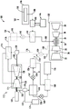
Referring now to FIG. 2, a schematic flow diagram of a gas turbine engine assembly 100 in accordance with an exemplary embodiment of the present disclosure is provided. The exemplary gas turbine engine assembly 100 of FIG. 2 may be constructed in substantially the same manner as the exemplary gas turbine engine assembly described above with reference to FIG. 1. For example, the exemplary gas turbine engine assembly 100 generally includes a gas turbine engine having a turbomachine 102. The gas turbine engine may be, for example, a turbofan engine, a turboprop engine, a turboshaft engine, a turbojet engine, or the like.
For example, the gas turbine engine may be configured in a similar manner as turbofan engine 10 described above. Thus, as shown, the gas turbine engine of FIG. 2 may generally include a turbomachine 102, the turbomachine 102 having: a compressor section having a Low Pressure (LP) compressor 22 and a High Pressure (HP) compressor 24; a combustion section 26; a turbine section including a High Pressure (HP) turbine 28 and a Low Pressure (LP) turbine 30. The compressor section, combustion section 26 and turbine section are arranged in a serial flow order. A High Pressure (HP) shaft or spool 34 drivingly connects the HP turbine 28 to the HP compressor 24, and a Low Pressure (LP) shaft or spool 36 drivingly connects the LP turbine 30 to the LP compressor 22.
Moreover, the exemplary gas turbine engine assembly 100 of FIG. 2 includes a fuel delivery system 104 (which may be configured in a similar manner as the fuel delivery system 70 of FIG. 1), the fuel delivery system 104 being operable with the combustion section 26 of the turbomachine 102 of the exemplary gas turbine engine for providing fuel to the combustion section 26 of the turbomachine 102 of the exemplary gas turbine engine. For the depicted embodiment, the fuel delivery system 104 generally includes a high temperature fuel source 106 and a plurality of fuel lines 108, the plurality of fuel lines 108 delivering fuel from the high temperature fuel source 106 to the combustion section 26 of the turbomachine 102. The high temperature fuel source 106 includes an oxygen reduction unit 110 to reduce the oxygen level in the fuel to minimize the risk of coking of the fuel when exposed to a relative altitude, as will be discussed in more detail below. The oxygen reduction unit 110 may be, for example, a fuel deoxygenation unit, a fuel oxygen conversion unit, or other system or structure that performs such a function. Although not depicted, the oxygen reduction unit 110 may receive a fuel stream from one or more fuel tanks of an aircraft including the gas turbine engine assembly 100 and provide the fuel stream to the plurality of fuel lines 108.
Still referring to FIG. 2, exemplary gas turbine engine assembly 100 also includes an air cycle assembly 112. The air cycle assembly 112 generally includes an air cycle machine 114 and an air cycle system ("ACS") heat exchanger 116. The air cycle machine 114 is in air flow communication with a compressor section of the turbomachine 102, and the ACS heat exchanger 116 is in air flow communication with the air cycle machine 114.
For the depicted embodiment, the exemplary air circulation assembly 112 includes a bleed air flow line 118, the bleed air flow line 118 being in air flow communication with a compressor section of the turbine 102 of the exemplary gas turbine engine. More specifically, the bleed air flow line 118 is in airflow communication with the HP compressor 24, and more specifically, the bleed air flow line 118 further includes a first portion 120 in airflow communication with a high pressure end of the HP compressor 24 and a second portion 122 in airflow communication with a low pressure end of the HP compressor 24. For example, the first portion 120 may be configured to receive the bleed air flow from a downstream stage of the HP compressor 24 at a relatively high pressure, and the second portion 122 may be configured to receive the bleed air flow from an upstream stage of the HP compressor 24 at a relatively low pressure. It should be appreciated that, in general, the air circulation assembly 112 requires a certain driving pressure from the bleed airflow received through the bleed airflow line 118. For example, while it is generally preferred to take the bleed air flow from the upstream/low pressure stage of the HP compressor 24 for efficiency purposes, this may not be practical during all operating conditions of the turbine 102. Thus, for example, the bleed air flow may be taken from a downstream stage (i.e., a high pressure stage) of the HP compressor 24 during low power conditions and an upstream stage (i.e., a low pressure stage) of the HP compressor 24 during high power conditions.
The first portion 120 and the second portion 122 of the bleed air flow line 118 meet at a three-way valve 124 (also referred to as a bleed port switch valve) of the bleed air flow line 118 where the bleed air flow from the first portion 120 and the bleed air flow from the second portion 122 merge. The three-way valve 124 may be a variable valve that is operatively connected to, for example, a controller (not shown) of the gas turbine engine to control the pressure of the bleed air flow provided to the air cycle machine 114 through the bleed air flow line 118. It is noted that although not depicted, a pressure regulator and/or an emergency shut-off valve may additionally be provided in the bleed air flow line 118 to ensure that over-pressure and/or over-temperature events do not damage the air circulation assembly 112.
However, it should be appreciated that, in other exemplary embodiments, the bleed air flow line 118 may include any other suitable structure or configuration for receiving the bleed air flow from the compressor section of the turbomachine 102.
For the depicted embodiment, the air cycle assembly 112 also includes an ACS precooler 126. The bleed air flow line 118 is in air flow communication with the ACS precooler 126 at a location upstream of the air cycle machine 114. As will be described in greater detail below, the ACS precooler 126 may provide an initial amount of cooling to the bleed air flow provided to the air cycle machine 114 via the bleed air flow line 118. However, it should be understood that in other embodiments, the air cycle assembly 112 may not include the ACS precooler 126, or any other suitable ACS precooler 126 configuration may be provided.
A bleed airflow line 118 then provides the bleed airflow to the air cycle machine 114. As depicted, the example air cycle machine 114 of FIG. 2 generally includes a compressor 128 for receiving and compressing the bleed air flow from the compressor section of the turbomachine 102 (i.e., through the bleed air flow line 118), and a turbine 130 rotatable with the compressor 128 and positioned downstream of the compressor 128. More specifically, compressor 128 is coupled to turbine 130 via an ACS shaft 132. The compressor 128 may generally compress the bleed airflow provided thereto (increasing the temperature and pressure of such bleed airflow), while the turbine 130 of the air cycle machine 114 may generally expand and cool the previously compressed bleed airflow from the compressor 128.
Moreover, as stated, the exemplary air cycle assembly 112 generally includes an ACS heat exchanger 116 in airflow communication with the air cycle machine 114. More specifically, for the depicted embodiment, the ACS heat exchanger 116 is in airflow communication with a compressor 128 of the air cycle machine 114 at a location downstream of the compressor 128 of the air cycle machine 114 and with a turbine 130 of the air cycle machine 114 at a location upstream of the turbine 130 of the air cycle machine 114. In this manner, the bleed air streams compressed by the compressor 128 of the air cycle machine 114 can be provided to the ACS heat exchanger 116, and such bleed air streams can then be provided from the ACS heat exchanger 116 to the turbine 130 of the air cycle machine 114.
Further, still referring to FIG. 2, to remove heat from the compressed bleed air flow passing through the ACS heat exchanger 116, the gas turbine engine assembly 100 also includes a heat transfer bus 134. The exemplary heat transfer bus 134 thermally couples the ACS heat exchanger 116 of the air cycle assembly 112 to the fuel delivery system 104. In this manner, the heat transfer bus 134 may generally transfer heat from the bleed air flow passing through the air cycle machine 114 (or, more specifically, through the ACS heat exchanger 116) to the fuel delivery system 104. Such a configuration allows the heat transfer bus 134 to act as a buffer between the compressed bleed air flow and the fuel flow through the fuel delivery system 104 to reduce or eliminate the possibility of fuel and high temperature air mixing outside of the combustion section 26 of the turbomachine 102.
It will be appreciated that compressing the bleed air flow (and thereby increasing the temperature and pressure of such bleed air flow) prior to being provided to the ACS heat exchanger 116 allows more heat to be removed from such bleed air flow such that a lower overall temperature may be achieved when the bleed air flow is subsequently expanded by the turbine 130 of the air cycle machine 114. More specifically, compressing the bleed air flow prior to providing such bleed air flow to the ACS heat exchanger 116 creates a greater temperature differential between the bleed air flow and the heat exchange fluid passing through the heat transfer bus 134 to facilitate greater heat transfer therebetween.
For the depicted embodiment, the heat transfer bus 134 generally includes a series of conduits 136, a pump 138 for generating a flow of heat transfer fluid through the series of conduits 136, a thermal energy storage unit 140, a valve 142, and a fuel heat exchanger 144. During operation, the series of conduits 136 provide a heat transfer fluid through the ACS heat exchanger 116, wherein the heat transfer fluid receives heat from the bypass air flow through the ACS heat exchanger 116. The heated heat transfer fluid then flows through the thermal energy storage unit 140, where thermal energy may be stored during at least some operations. For example, during certain operations, the thermal energy storage unit 140 may include an energy storage medium, such as a wax, liquid metal, molten salt, fusible alloy, or the like, to absorb thermal energy and then release such thermal energy as needed. For example, the thermal energy storage unit 140 may store heat during operation and subsequently release heat during conditions such as when the air circulation assembly 112 is not generating the desired heat. It is noted, however, that in other exemplary embodiments, the heat transfer bus 134 may not include the thermal energy storage unit 140.
Still referring to the embodiment of fig. 2, the heat transfer fluid may then flow through the valve 142 and to and through the fuel heat exchanger 144. Within the fuel heat exchanger 144, the heat transfer fluid may provide heat to a flow of fuel provided from the fuel delivery system 104 (and more specifically, from the fuel line 108). In this manner, the heat transfer bus 134 may transfer heat from the air cycle machine 114 to the fuel delivery system 104. It should be appreciated that increasing the temperature of the fuel stream provided to the combustion section 26 of the turbomachine 102 may generally result in more efficient operation of the turbomachine 102 as a whole.
It should be understood that for the depicted embodiment, the heat transfer bus 134 uses a single phase heat transfer fluid during operation. More specifically, during operation of gas turbine engine assembly 100, substantially all of the heat transfer fluid passing through heat transfer bus 134 remains in a single phase (e.g., liquid phase, gas phase, or supercritical phase). However, in other embodiments, the heat transfer bus 134 may instead use a phase change fluid configured to change phase during operation.
Notably, for the depicted exemplary embodiment, the fuel delivery system 104 is also thermally coupled to the lubrication system 146 of the gas turbine engine assembly 100. The lubrication system 146 may be an oil lubrication system for a plurality of bearings within a gas turbine engine (not shown). As also depicted, the fuel delivery system 104 also includes a fuel-cooling oil cooler 148 located at a location upstream of the fuel heat exchanger 144. The fuel-cooling oil cooler 148 thermally couples the lubrication system 146 to the flow of fuel through the fuel delivery system 104 such that the flow of fuel through the fuel delivery system 104 may receive heat from the lubrication system 146 to reduce the temperature of the lubrication oil of the lubrication system 146 and increase the temperature of the flow of fuel through the fuel delivery system 104 (and more specifically, the fuel line 108).
Referring now back to the air cycle assembly 112 of the exemplary gas turbine engine assembly 100 of FIG. 2, it should be appreciated that the depicted exemplary air cycle machine 114 is also mechanically coupled to an electric machine. More specifically, the electric machine is configured as a starter motor/generator 150. In this manner, the starter motor/generator 150 may be operable to start the air cycle machine 114 during, for example, a start-up operation of the gas turbine engine assembly 100, wherein the flow of bleed air from the gas turbine engine may be less than an amount required to drive the air cycle machine 114. However, in other operations, the amount of bleed air flow extracted from the gas turbine engine may exceed the amount required to drive the air cycle machine 114. In such exemplary aspects, the air cycle machine 114 may instead drive the starter motor/generator 150 such that the exemplary starter motor/generator 150 generates excess electrical power, which may be used in any suitable manner.
Further, as previously described, the bleed air flow provided to the air cycle machine 114 (via the bleed air line 118) is expanded and cooled by the turbine 130 of the air cycle machine 114, then compressed by the compressor 128 and cooled by the ACS heat exchanger 116. This expansion generates mechanical power for driving the air cycle machine 114. The expanded and cooled bleed air flow from the turbine 130 of the air cycle machine 114 is then provided through an outlet duct assembly 152. For the exemplary embodiment shown, air cycle assembly 112 also includes a thermal energy storage unit 154 in airflow communication with air cycle machine 114 at a location downstream of air cycle machine 114. More specifically, the thermal energy storage unit 154 is in airflow communication with the air cycle machine 114 through the outlet duct assembly 152. The example thermal energy storage unit 154 may include any suitable configuration for storing thermal energy. For example, in certain embodiments, the thermal energy storage unit 154 may include a phase change material, such as a bulk metal molten salt, a liquid metal, a wax, a compressed gas, or the like. The thermal energy storage unit 154 may store energy in the form of such cooled material during operation and subsequently release energy when the air cycle machine 114 is not providing a flow of cooled air (or a desired amount of cooled air). For example, the thermal energy storage unit 154 may release cooled material to generate a cooled airflow during shutdown of the turbomachine 102 to reduce the risk of a curved rotor condition.
Still referring to the embodiment of fig. 2, the thermal energy storage unit 154 may provide a cooled bleed air flow through the first path 156 or the second path 158 of the example outlet duct assembly 152. The first path 156 provides the cooled bleed air flow to the ACS precooler 126 and through the ACS precooler 126. As mentioned briefly above, the ACS precooler 126 (which is just the air-to-air heat exchanger for the depicted embodiment) may transfer heat from the bleed air flow of the compressor section of the turbomachine 102 (i.e., via the line 118) to the cooling air flow from the air cycle machine 114 via the first path 156. Accordingly, the ACS precooler 126 may cool the bleed air flow through the line 118 before providing such bleed air flow to the air cycle machine 114. The cooled air flow through the first path 156 (which has received some heat through the ACS precooler 126) is then provided to the mixing chamber 160 of the air circulation assembly 112. Instead, the second path 158 extends directly from the thermal energy storage unit 154 to the mixing chamber 160.
Further, for the exemplary embodiment shown, air circulation assembly 112 also includes a first valve 162 positioned within first path 156 of outlet duct assembly 152 and a second valve 164 positioned within second path 158 of outlet duct assembly 152. The first and second valves 162, 164 may each be variable throughput valves to vary the amount of airflow allowable through the first and second paths 156, 158, respectively. It is noted, however, that in other embodiments, air circulation assembly 112 may not include one of first valve 162 or second valve 164, or alternatively may include a variable three-way valve at the junction between first path 156 and second path 158 (within cell 154 of the illustrated embodiment). For example, in other embodiments, air circulation assembly 112 may not include thermal energy storage unit 154, and may instead include a variable throughput three-way valve.
Further, within the mixing chamber 160, the cooled bleed air flow from the first path 156 and the cooled bleed air flow from the second path 158 may be mixed together and provided to the radiator 166. Radiator 166 may be any suitable radiator 166 for an exemplary gas turbine engine and/or aircraft that includes an exemplary gas turbine engine. For example, in certain exemplary embodiments, the radiator 166 may be a cooled compressor air system, one or more of a radiator for a low pressure turbine or other turbine component, a sump (such that airflow is used for sump cooling), an environmental control system or other aircraft thermal load, or the like.
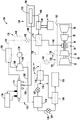
However, it should be appreciated that in other exemplary embodiments, the exemplary gas turbine engine assembly 100 may alternatively have any other suitable configuration. For example, referring now to fig. 3 and 4, two additional embodiments of a gas turbine engine assembly 100 according to other exemplary embodiments are provided. Each of the embodiments of FIGS. 3 and 4 is constructed in substantially the same manner as the exemplary gas turbine engine assembly 100 described above with reference to FIG. 2. For example, the exemplary gas turbine engine assemblies 100 of FIGS. 3 and 4 each include a gas turbine engine having a turbomachine 102, a fuel delivery system 104, an air circulation assembly 112, and a heat transfer bus 134. The heat transfer bus 134 is configured to thermally couple the ACS heat exchanger 116 of the air cycle assembly 112 to the fuel delivery system 104 to transfer heat from the air cycle machine 114 of the air cycle assembly 112 to the fuel delivery system 104.
Further, the heat transfer bus 134 depicted in each of fig. 3 and 4 includes a pump 138 for providing flow of the heat transfer fluid through the series of conduits 136 of the heat transfer bus 134. It is noted, however, that for the embodiment of fig. 3 and 4, pump 138 is typically powered by an aspect of air circulation assembly 112.
More specifically, with particular reference to FIG. 3, pump 138 is configured as a turbo pump having a power turbine 168, the power turbine 168 being in airflow communication with the compressor section of the turbine 102 and the compressor 128 of the air cycle machine 114 at a location upstream of the compressor 128 of the air cycle machine 114. Further, for the exemplary embodiment shown, the turbo-pump power turbine 168 is further located upstream of the ACS precooler 126 of the air cycle assembly 112. In this manner, the flow of bleed air from the compressor section of the turbine 102 may flow through the power turbine 168 of the turbine pump to power the turbine pump.
Further, referring now specifically to FIG. 4, for the exemplary embodiment shown, pump 138 is powered directly by air cycle machine 114 of air cycle assembly 112. More specifically, for the exemplary embodiment of FIG. 4, shaft 132 of air cycle machine 114 extends from compressor 128 to pump 138 to mechanically power or drive pump 138 of heat transfer bus 134 during operation of gas turbine engine assembly 100. Although shown as a continuous shaft 132, in other exemplary embodiments, the shaft 132 may alternatively be formed from multiple components.
Notably, as also depicted in FIG. 4, the air cycle assembly 112 of the gas turbine engine assembly 100 also includes a condensation separator 170, the condensation separator 170 being located downstream of the air cycle machine 114 and upstream of the thermal energy storage unit 154 (for the exemplary embodiment shown) of the air cycle assembly 112. Condensate separator 170 is configured to provide a sub-freezing discharge to thermal energy storage unit 154 while separating out a dry cold airflow. The dry cool airflow is provided to a heat sink 174 (which may be the same heat sink 166 that receives the airflow from the mixing chamber 160 of the air circulation assembly 112) through a separate duct 172. The inclusion of the condensate separator 170 may ensure that components that may be damaged by such subfreezing emissions are not provided with any subfreezing emissions (e.g., ice).
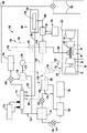
Moreover, in other exemplary embodiments of the present disclosure, the gas turbine engine assembly 100 may also have other suitable configurations. For example, referring now to fig. 5 and 6, a gas turbine engine assembly 100 in accordance with yet another exemplary embodiment of the present disclosure is provided. The exemplary gas turbine engine assembly 100 of fig. 5 and 6 may be constructed in substantially the same manner as the exemplary gas turbine engine assembly 100 described above with reference to, for example, fig. 2.
For example, with particular reference to FIG. 6, a schematic flow diagram of an exemplary gas turbine engine assembly 100 is provided, the exemplary gas turbine engine assembly 100 generally including a gas turbine engine having a turbomachine 102, a fuel delivery system 104, an air circulation assembly 112, and a heat transfer bus 134. The turbomachine 102 generally includes a compressor section having one or more compressors configured to provide a flow of bleed air to the air circulation assembly 112 via a bleed air flow line 118. Additionally, the heat transfer bus 134 is configured to thermally couple the ACS heat exchanger 116 of the air cycle assembly 112 to the fuel delivery system 104 to transfer heat from the air cycle machine 114 of the air cycle assembly 112 to the fuel delivery system 104.
Moreover, as indicated, the example air cycle assembly 112 of FIGS. 5 and 6 also includes an air cycle machine 114 configured to receive a flow of bleed air from a compressor section of the turbine 102 of the example gas turbine engine. The example air cycle machine 114 is an "open loop" air cycle machine 114, similar to the embodiments described above. However, for the embodiment shown, the air cycle machine 114 is a "3-wheel" air cycle machine 114 (as opposed to the "2-wheel" air cycle machine described above).
More specifically, with particular reference to FIG. 6, a close-up schematic view of an exemplary air cycle machine 114 is provided, the exemplary air cycle machine 114 shown including a compressor 128 and a turbine. More specifically, the turbine is the first turbine 130, and the air cycle machine 114 also includes a second turbine 176 and a combustor 178. The combustor 178 is in gas flow communication with the second turbine 176 at a location upstream of the second turbine 176. Additionally, the second turbine 176 may rotate with the compressor 128 of the air cycle machine 114 and the first turbine 130 of the air cycle machine 114 via the common ACS shaft 132. It should be understood, however, that although ACS shaft 132 is schematically depicted as a single component for the illustrated embodiment, in other exemplary embodiments ACS shaft 132 may alternatively be configured as multiple components that are joined in any suitable manner. Additionally, one or more of the variator mechanisms may be provided with the ACS shaft 132 so that certain parts may rotate at a different speed than other parts.
Briefly, as shown, the example air cycle machine 114 of FIG. 5 also includes an electric machine (i.e., a starter motor/generator 150 for the depicted embodiment) that may rotate with the ACS shaft 132 or that is coupled to the ACS shaft 132. In this manner, the starter motor/generator 150 may be operable to assist in starting the air cycle machine 114 during certain operations (e.g., where the flow of bleed air provided thereto is insufficient to drive the air cycle machine 114) and may also be operable to extract power from the air cycle machine 114 during other operations (e.g., where the flow of bleed air provided thereto is sufficient to drive the air cycle machine 114).
Referring now specifically back to FIG. 5, it should be appreciated that the example air cycle machine 114, or more specifically, the combustor 178 of the example air cycle machine 114, is operable with the fuel delivery system 104 to receive a flow of fuel from the fuel delivery system 104. In addition, the air cycle machine 114 is operable to receive two separate flows of bleed air streams from the compressor section of the turbine 102 shown in FIG. 6. In particular, for the depicted embodiment, the flow of the two bleed air streams is distributed between the first and second supply lines 180, 182, divided within the bleed air lines 118 via diverter valves 184. For the illustrated embodiment, the first supply line 180 provides a flow of the first stream of bleed air through the ACS precooler 126 and to the compressor 128 of the air cycle machine 114. Conversely, the second supply line 182 provides a flow of a second stream of bleed air to the burner 178 of the air cycle machine 114. The flow of the second stream of bleed air may then be mixed and combusted within the combustor 178 with the fuel stream provided by the fuel delivery system 104 to generate combustion gases. The combustion gases may then be provided to a second turbine 176 of the air cycle machine 114, thereby expanding such combustion gases and extracting energy therefrom to help power the air cycle machine 114.
As shown in FIG. 6 and described above, the air cycle assembly 112 also includes an ACS heat exchanger. More specifically, for the depicted embodiment, the air cycle assembly 112 includes a first ACS heat exchanger 116 and a second ACS heat exchanger 186. The first ACS heat exchanger 116 is in airflow communication with the compressor 128 and the first turbine 130 of the air cycle machine 114 in substantially the same manner as the exemplary ACS heat exchanger 116 described above with reference to FIG. 2. In addition, a second ACS heat exchanger 186 is in airflow communication with the second turbine 176 to receive the exhaust gas flow from the second turbine 176 of the air cycle machine 114.
Each of the first ACS heat exchanger 116 and the second ACS heat exchanger 186 is operable to remove heat from the respective air flow passing therethrough from the air cycle machine 114. For the exemplary embodiment shown, the first ACS heat exchanger 116 may be in thermal communication with, for example, a bypass air flow path of a gas turbine engine (e.g., the exemplary bypass air flow path 56 described above with reference to FIG. 1). In this manner, the first ACS heat exchanger 116 can utilize the bypass air flow path as a radiator for the air cycle machine 114. Instead, the second ACS heat exchanger 186 is thermally coupled to the heat transfer bus 134 such that heat can be extracted from the exhaust gas flow passing through the second ACS heat exchanger 186 and then provided to the fuel delivery system 104 (i.e., through the fuel heat exchanger 144, as described above). However, it should be understood that in other embodiments, the first ACS heat exchanger 116 may also be thermally coupled to the heat transfer bus 134 or any other suitable heat sink, and further in other embodiments, the second ACS heat exchanger 186 may also optionally be thermally coupled to any other suitable heat sink, such as a bypass airflow channel (see fig. 8).
Still referring to the embodiment of fig. 5 and 6, as with the previous embodiment, the cooled and expanded air flow from the first turbine 130 (downstream of the first ACS heat exchanger 116 and compressor 128) is provided through an outlet duct assembly 152 and, more specifically, for the depicted embodiment, to an ACS thermal energy storage unit 154. The expanded and cooled air flow may then be provided to the ACS precooler 126 via path 156 or directly to the mixing chamber 160 via path 158 before being used to cool the radiator.
Additionally, for the embodiment of fig. 5 and 6, the air flow from the second turbine 176 cooled by the second ACS heat exchanger 186 is used to drive the pump 138 of the heat transfer bus 134 prior to being provided to the outlet duct assembly 152 of the air cycle assembly 112. More specifically, for the illustrated embodiment, the heat transfer bus 134 utilizes a turbopump having a power turbine 168. The air flow from the second ACS heat exchanger 186 is provided through the turbo-pump power turbine 168 to drive the turbo-pump and, for example, circulate the heat transfer fluid through the heat transfer bus 134. The power turbine 168 expands the airflow therethrough, thereby extracting energy and reducing the temperature thereof. Although not shown, separate mixing chambers or valves may be utilized to join the airflow from the turbopump with the airflow from the first turbine 130 of the air cycle machine 114 within the outlet duct assembly 152 at a location upstream of the thermal energy storage unit 154. However, it is noted that in other embodiments, the gas flow from the turbo pump may be joined with the outlet duct assembly 152 at any other suitable location (e.g., downstream of the thermal energy storage unit 154, at the mixing chamber 160, etc.).
It should also be understood that the exemplary embodiment described with reference to fig. 5 and 6 is one exemplary embodiment of the present disclosure. In other embodiments, the gas turbine engine assembly 100 may have other suitable configurations. For example, in other exemplary embodiments, the pump 138 of the heat transfer bus 134 may instead be driven directly by the air cycle machine 114 (e.g., via the ACS shaft 132; see, e.g., FIG. 4), or by any other suitable power source. Moreover, in other exemplary embodiments, the air flow from the second ACS heat exchanger 186 may not be provided to the outlet duct assembly 152, but may instead be provided to any other suitable radiator (see fig. 7 below). Moreover, in other exemplary embodiments, the second ACS heat exchanger 186 may not be in thermal communication with the heat transfer bus 134 (see fig. 8 below).
For example, referring now specifically to fig. 7, a schematic diagram of another exemplary embodiment of the present disclosure is provided. The exemplary gas turbine engine assembly 100 depicted in FIG. 7 may be constructed in substantially the same manner as the exemplary gas turbine engine assembly 100 described above with reference to FIGS. 5 and 6. However, for the exemplary embodiment of FIG. 7, the air flow provided through the second ACS heat exchanger 186, and thus cooled by the heat transfer bus 134, is not used to drive the pump 138 of the heat transfer bus 134. Alternatively, the cooling air flow from the second ACS heat exchanger 186 is directed to one or more radiators of the turbine 102 of the gas turbine engine via one or more conduits 190. Specifically, for the exemplary aspect depicted in FIG. 7, the cooled air flow from the second ACS heat exchanger 186 is provided directly to the low pressure turbine 22 of the exemplary gas turbine engine turbine 102 and the high pressure compressor 30 of the exemplary gas turbine engine turbine 102. Notably, for the embodiment of FIG. 7, a portion of the airflow from the second turbine 176 of the air cycle machine 114 is additionally used to drive the pump 138 of the heat transfer bus 134. Specifically, the air cycle assembly 112 includes a three-way variable valve 188 at a location downstream of the second turbine 176 of the air cycle machine 114 and upstream of the second ACS heat exchanger 186 for shunting the flow of the power turbine 168 of the pump 138 through the heat transfer bus 134 (such that the pump 138 is configured as a turbopump).
Alternatively, by way of example, referring now in particular to fig. 8, a schematic illustration of yet another exemplary embodiment of the present disclosure is provided. The exemplary gas turbine engine assembly 100 depicted in FIG. 8 may be constructed in substantially the same manner as the exemplary gas turbine engine assembly 100 described above with reference to FIGS. 5 and 6. However, for the exemplary embodiment of FIG. 8, the second ACS heat exchanger 186 is not in thermal communication with the heat transfer bus 134. Alternatively, for the embodiment of fig. 8, the second ACS heat exchanger 186 may be in thermal communication with, for example, a gas turbine engine bypass airflow path (e.g., the exemplary bypass airflow path 56 described above with reference to fig. 1). In this manner, the second ACS heat exchanger 186 can utilize the bypass air flow path as a heat sink for the air cycle machine 114. In contrast, for the depicted embodiment, the first ACS heat exchanger 116 is thermally coupled to the heat transfer bus 134 such that heat can be extracted from the air flow passing through the first ACS heat exchanger 116 and then provided to the fuel delivery system 104 (i.e., through the fuel heat exchanger 144, as described above). In this manner, each of the first ACS heat exchanger 116 and the second ACS heat exchanger 186 is still operable to remove heat from the respective air flow passing through the air cycle machine 114.
According to one or more exemplary embodiments of the present disclosure, including air circulation assembly 112 may allow for a more efficient air circulation assembly 112 and gas turbine engine. More specifically, utilizing an air cycle assembly 112 configured to exchange heat with a fuel delivery system 104 of a gas turbine engine assembly 100 via an intermediate heat transfer bus 134 may allow a relatively large amount of heat to be efficiently removed from an air cycle machine 114 of the air cycle assembly 112 while utilizing such heat to increase a temperature of a flow of fuel through the fuel delivery system 104 to increase combustion efficiency within a turbine 102 of the exemplary gas turbine engine assembly 100.
Referring now to FIG. 9, a flow chart of a method 200 for operating a gas turbine engine assembly according to an exemplary aspect of the present disclosure is provided. The exemplary method 200 of FIG. 9 may operate one or more of the exemplary gas turbine engine assemblies 100 described above with reference to FIGS. 1-7. Accordingly, the exemplary gas turbine engine assembly operated by the exemplary method 200 of FIG. 9 may generally include a turbomachine, a fuel delivery system and air circulation assembly, and a heat transfer bus.
The exemplary method 200 generally includes, at (202), providing a flow of bleed air from a compressor section of a turbine to an air cycle machine of an air cycle assembly. Additionally, the example method 200 includes transferring heat from a bleed air flow through an air cycle machine of the air cycle assembly to a fuel delivery system through a heat transfer bus to cool the air flow through the air cycle machine of the air cycle assembly at (204).
For the exemplary aspect depicted in FIG. 9, transferring heat from the bleed air flow through the air cycle machine of the air cycle assembly to the fuel delivery system via the heat transfer bus at (204) includes reducing a temperature of the bleed air flow through the air cycle machine by at least about 150 degrees Fahrenheit using an ACS heat exchanger thermally coupled to the heat transfer bus at (206). For example, reducing the temperature of the bleed air flow through the air cycle machine at (206) may include reducing the temperature of the bleed air flow through the air cycle machine by at least about 250 degrees Fahrenheit, such as at least about 300 degrees Fahrenheit, such as at least about 350 degrees Fahrenheit, such as up to 1000 degrees Fahrenheit, such as up to 750 degrees Fahrenheit.
Also for the exemplary aspect depicted in FIG. 9, transferring heat from the bleed air flow through the air cycle machine of the air cycle assembly to the fuel delivery system through the heat transfer bus at (204) further includes increasing a temperature of a fuel flow through the fuel delivery system by at least about 200 degrees Fahrenheit at (208). For example, increasing the temperature of the fuel at (208) may include increasing the temperature of the fuel by at least about 300 degrees Fahrenheit, such as at least about 375 degrees Fahrenheit, such as at least about 425 degrees Fahrenheit, such as at least about 475 degrees Fahrenheit, such as up to about 1250 degrees Fahrenheit, such as up to about 900 degrees Fahrenheit.
Further, for the exemplary aspect depicted in FIG. 9, still further transferring heat from the bleed air flow through the air cycle machine of the air cycle assembly to the fuel delivery system through the heat transfer bus at (204) to cool the air flow through the air cycle machine of the air cycle assembly further includes circulating a heat transfer fluid through one or more conduits of the heat transfer bus between an ACS heat exchanger thermally coupling the heat transfer fluid to the bleed air flow and a fuel heat exchanger thermally coupling the heat transfer fluid to a fuel flow through the fuel delivery system at (210). Although not shown in fig. 9, in certain exemplary aspects, circulating the heat transfer fluid at (210) may include maintaining the heat transfer fluid in a consistent state, such as a gaseous, liquid, or supercritical state.
Additionally, the example method 200 depicted in fig. 9 also includes providing the bleed air flow from the air cycle machine to an output assembly of the air cycle assembly at an absolute pressure greater than about 50 psig and less than about 600 psig at (212). For example, in certain exemplary aspects, the method 200 may provide the flow of bleed air from the air cycle machine to an output assembly of the air cycle assembly at a pressure greater than about 75 psig (e.g., greater than about 100 psig, such as less than about 600 psig, such as less than about 450 psig, such as less than about 300 psig).
This written description uses examples to disclose the invention, including the best mode, and also to enable any person skilled in the art to practice the invention, including making and using any devices or systems and performing any incorporated methods. The patentable scope of the invention is defined by the claims, and may include other examples that occur to those skilled in the art. Such other examples are intended to be within the scope of the claims if they include structural elements that do not differ from the literal language of the claims, or if they include equivalent structural elements with insubstantial differences from the literal languages of the claims.
The various features, aspects, and advantages of the present invention may also be embodied in the various aspects described in the following clauses, which may be combined in any combination:
1. a gas turbine engine assembly, comprising:
a turbine comprising, in serial flow order, a compressor section, a combustion section, and a turbine section;
a fuel delivery system operable with the combustion section of the turbomachine for providing fuel to the combustion section of the turbomachine;
an air cycle assembly including an air cycle machine and a heat exchanger, the air cycle machine in airflow communication with the compressor section of the turbine and the heat exchanger in airflow communication with the air cycle machine; and
a heat transfer bus thermally coupling the heat exchanger of the air cycle assembly to the fuel delivery system for transferring heat from the air cycle machine to the fuel delivery system.
2. The gas turbine engine assembly of clause 1, wherein the heat transfer bus comprises a thermal energy storage unit.
3. The gas turbine engine assembly of clause 1, wherein the heat exchanger of the air cycle assembly is an ACS heat exchanger, wherein the heat transfer bus comprises a fuel heat exchanger for transferring heat to the fuel delivery system, and wherein the fuel delivery system comprises a fuel-cooling oil cooler located at a position upstream of the fuel heat exchanger.
4. The gas turbine engine assembly of clause 1, wherein the air cycle assembly includes a thermal energy storage unit located at a location downstream of the air cycle machine.
5. The gas turbine engine assembly of clause 1, wherein the heat transfer bus comprises a pump, and wherein the pump is mechanically driven by the air cycle machine.
6. The gas turbine engine assembly of clause 1, wherein the heat transfer bus comprises a turbo pump, wherein the turbo pump comprises a power turbine in airflow communication with the compressor section of the turbine at a location upstream of the air cycle machine.
7. The gas turbine engine assembly of clause 1, wherein the air cycle machine includes a compressor for receiving and compressing the flow of bleed air from a compressor section of the turbine and a turbine rotating with the compressor and positioned downstream of the compressor, the turbine of the air cycle machine being configured to expand and cool the flow of compressed bleed air from the compressor.
8. The gas turbine engine assembly of clause 7, wherein the heat exchanger is in airflow communication with the compressor of the air cycle machine at a location downstream of the compressor of the air cycle machine and in airflow communication with the turbine of the air cycle machine at a location upstream of the turbine of the air cycle machine.
9. The gas turbine engine assembly of clause 7, wherein the turbine of the air cycle machine is a first turbine, wherein the air cycle machine further comprises a second turbine and a combustor, wherein the combustor is positioned upstream of the second turbine, and wherein the second turbine is rotatable with the compressor of the air cycle machine.
10. The gas turbine engine assembly of clause 9, wherein the heat exchanger is in airflow communication with the second turbine of the air cycle machine at a location downstream of the second turbine of the air cycle machine.
11. The gas turbine engine assembly of clause 9, wherein the heat exchanger of the air cycle assembly is a first ACS heat exchanger, wherein the air cycle assembly further comprises a second ACS heat exchanger, wherein the first ACS heat exchanger is positioned downstream of the compressor of the air cycle machine and upstream of the first turbine of the air cycle machine.
12. The gas turbine engine assembly of clause 11, wherein the second ACS heat exchanger is in thermal communication with a bypass airflow path of the gas turbine engine.
13. The gas turbine engine assembly of clause 9, wherein the heat exchanger of the air cycle assembly is a second ACS heat exchanger, wherein the air cycle assembly further comprises a first ACS heat exchanger, wherein the first ACS heat exchanger is positioned downstream of the compressor of the air cycle machine and upstream of the first turbine of the air cycle machine, wherein the second ACS heat exchanger is positioned downstream of the second turbine, and wherein the second ACS heat exchanger is in thermal communication with a bypass airflow path of the gas turbine engine.
14. The gas turbine engine assembly of clause 9, wherein the heat transfer bus comprises a turbo pump, wherein the turbo pump comprises a power turbine in airflow communication with the air cycle machine at a location downstream of the second turbine of the air cycle machine.
15. The gas turbine engine assembly of clause 1, wherein the heat transfer bus uses a single phase heat transfer fluid during operation.
16. A method for operating the gas turbine engine assembly, the gas turbine engine assembly including a turbine, a fuel delivery system, an air circulation assembly, and a heat transfer bus, the method comprising:
providing a flow of bleed air from a compressor section of the turbine to an air cycle machine of the air cycle assembly; and
transferring heat from the bleed air flow through the air cycle machine of the air cycle assembly to the fuel delivery system through the heat transfer bus to cool the air flow through the air cycle machine of the air cycle assembly.
17. The method of clause 16, wherein transferring heat from the bleed air flow through the air cycle machine of the air cycle assembly to the fuel delivery system via the heat transfer bus comprises reducing a temperature of the bleed air flow by at least about 150 degrees fahrenheit using an ACS heat exchanger thermally coupled to the heat transfer bus.
18. The method of clause 16, wherein transferring heat from the bleed air flow through the air cycle machine of the air cycle assembly to the fuel delivery system via the heat transfer bus further comprises increasing a temperature of a fuel flow through the fuel delivery system by at least about 200 degrees fahrenheit.
19. The method of clause 16, further comprising:
the bleed air flow from the air cycle machine is provided to an output assembly of the air cycle assembly at an absolute pressure greater than about 50 pounds per square inch and less than about 600 pounds per square inch.
20. The method of clause 16, wherein transferring heat from the bleed air flow through the air cycle machine of the air cycle assembly to the fuel delivery system through the heat transfer bus to cool the air flow through the air cycle machine of the air cycle assembly comprises circulating a heat transfer fluid through one or more conduits of the heat transfer bus between an ACS heat exchanger thermally coupling the heat transfer fluid to the bleed air flow and a fuel heat exchanger thermally coupling the heat transfer fluid to a fuel flow through the fuel delivery system.