CN110310255B - Point switch notch detection method based on target detection and image processing - Google Patents
Point switch notch detection method based on target detection and image processing Download PDFInfo
- Publication number
- CN110310255B CN110310255B CN201910439304.0A CN201910439304A CN110310255B CN 110310255 B CN110310255 B CN 110310255B CN 201910439304 A CN201910439304 A CN 201910439304A CN 110310255 B CN110310255 B CN 110310255B
- Authority
- CN
- China
- Prior art keywords
- image
- notch
- gap
- layer
- value
- Prior art date
- Legal status (The legal status is an assumption and is not a legal conclusion. Google has not performed a legal analysis and makes no representation as to the accuracy of the status listed.)
- Active
Links
Images


Classifications
-
- G—PHYSICS
- G06—COMPUTING OR CALCULATING; COUNTING
- G06T—IMAGE DATA PROCESSING OR GENERATION, IN GENERAL
- G06T7/00—Image analysis
- G06T7/0002—Inspection of images, e.g. flaw detection
- G06T7/0004—Industrial image inspection
-
- G—PHYSICS
- G06—COMPUTING OR CALCULATING; COUNTING
- G06T—IMAGE DATA PROCESSING OR GENERATION, IN GENERAL
- G06T7/00—Image analysis
- G06T7/10—Segmentation; Edge detection
- G06T7/11—Region-based segmentation
-
- G—PHYSICS
- G06—COMPUTING OR CALCULATING; COUNTING
- G06T—IMAGE DATA PROCESSING OR GENERATION, IN GENERAL
- G06T7/00—Image analysis
- G06T7/10—Segmentation; Edge detection
- G06T7/136—Segmentation; Edge detection involving thresholding
-
- G—PHYSICS
- G06—COMPUTING OR CALCULATING; COUNTING
- G06T—IMAGE DATA PROCESSING OR GENERATION, IN GENERAL
- G06T2207/00—Indexing scheme for image analysis or image enhancement
- G06T2207/10—Image acquisition modality
- G06T2207/10004—Still image; Photographic image
-
- G—PHYSICS
- G06—COMPUTING OR CALCULATING; COUNTING
- G06T—IMAGE DATA PROCESSING OR GENERATION, IN GENERAL
- G06T2207/00—Indexing scheme for image analysis or image enhancement
- G06T2207/20—Special algorithmic details
- G06T2207/20081—Training; Learning
-
- G—PHYSICS
- G06—COMPUTING OR CALCULATING; COUNTING
- G06T—IMAGE DATA PROCESSING OR GENERATION, IN GENERAL
- G06T2207/00—Indexing scheme for image analysis or image enhancement
- G06T2207/20—Special algorithmic details
- G06T2207/20084—Artificial neural networks [ANN]
-
- G—PHYSICS
- G06—COMPUTING OR CALCULATING; COUNTING
- G06T—IMAGE DATA PROCESSING OR GENERATION, IN GENERAL
- G06T2207/00—Indexing scheme for image analysis or image enhancement
- G06T2207/30—Subject of image; Context of image processing
- G06T2207/30108—Industrial image inspection
- G06T2207/30164—Workpiece; Machine component
-
- G—PHYSICS
- G06—COMPUTING OR CALCULATING; COUNTING
- G06T—IMAGE DATA PROCESSING OR GENERATION, IN GENERAL
- G06T2207/00—Indexing scheme for image analysis or image enhancement
- G06T2207/30—Subject of image; Context of image processing
- G06T2207/30236—Traffic on road, railway or crossing
Landscapes
- Engineering & Computer Science (AREA)
- Computer Vision & Pattern Recognition (AREA)
- Physics & Mathematics (AREA)
- General Physics & Mathematics (AREA)
- Theoretical Computer Science (AREA)
- Quality & Reliability (AREA)
- Image Analysis (AREA)
Abstract
本发明提供了一种基于目标检测和图像处理的转辙机缺口检测方法,其中,该方法包括:采集列车经过道岔及转辙机带动道岔转换过程的转辙机缺口图像;建立目标检测网络并训练;将待测缺口图像输入训练好的目标检测网络,识别缺口图像中的目标区域,得到区域的边界框参数;根据区域的边界框参数对缺口图像进行预处理;对缺口图像进行缺口检测,包括缺口特征直线拟合、图像倾斜检测及矫正;根据所述缺口特征直线计算缺口值w。此发明可直接应用于各种类型转辙机,不需要针对不同类型转辙机设置不同的图像预处理参数,适用于复杂恶劣的运行工况,如缺口图像局部曝光过度、缺口图像倾斜,进一步提高缺口检测系统的准确率、鲁棒性和普适性。

The invention provides a switch machine gap detection method based on target detection and image processing, wherein the method includes: collecting the switch machine gap image of the train passing through the switch and the switch machine driving the switch conversion process; establishing a target detection network and Training; input the notch image to be tested into the trained target detection network, identify the target area in the notch image, and obtain the bounding box parameters of the area; preprocess the notch image according to the bounding box parameters of the area; perform notch detection on the notch image, It includes notch characteristic straight line fitting, image tilt detection and correction; the notch value w is calculated according to the notch characteristic straight line. This invention can be directly applied to various types of switch machines. It does not need to set different image preprocessing parameters for different types of switch machines. It is suitable for complex and harsh operating conditions, such as partial exposure of the gap image, tilt of the gap image, and further Improve the accuracy, robustness and universality of the gap detection system.
Description
技术领域technical field
本发明涉及轨道交通领域,具体涉及一种基于目标检测和图像处理的转辙机缺口检测方法。The invention relates to the field of rail transit, in particular to a method for detecting gaps in switch machines based on target detection and image processing.
背景技术Background technique
道岔是铁路中保障行车安全的重要设备,转辙机带动道岔移动能实现列车从一条轨道换到另一条轨道行驶,转辙机缺口偏移量检测能反映道岔的尖轨与基本轨是否密贴。当缺口过大时,不能为列车建立进路,否则可能发生列车脱轨等严重安全事故。因此,实时检测缺口大小对铁路的信号系统和应急响应非常重要,能够实时掌握缺口的情况。Turnout is an important equipment to ensure the safety of railway traffic. The switch machine drives the switch to move the train from one track to another. The detection of the gap offset of the switch machine can reflect whether the tip rail of the switch is closely attached to the basic rail. . When the gap is too large, the approach cannot be established for the train, otherwise serious safety accidents such as train derailment may occur. Therefore, real-time detection of the size of the gap is very important for the railway signaling system and emergency response, and the situation of the gap can be grasped in real time.
传统的转辙机缺口检测方法是人工巡检或在转辙机内部安装光电传感器、磁栅传感器等,这些方法受环境因素和人为因素的影响较大。目前铁路现场使用的转辙机缺口检测系统主要是基于视频图像的检测方法,在转辙机内部安装摄像头并配置相应的照明灯,对着缺口位置拍摄缺口视频,将缺口视频上传至主机后转化成帧图片,采用图像处理算法处理转辙机缺口图像,得到缺口值,这种方法具有准确性高、非接触、直观可视等优点。The traditional switch machine gap detection method is manual inspection or installing photoelectric sensors, magnetic grid sensors, etc. inside the switch machine. These methods are greatly affected by environmental factors and human factors. At present, the switch machine gap detection system used on the railway site is mainly based on the detection method of video images. A camera is installed inside the switch machine and corresponding lights are installed, and the gap video is taken at the gap position, and the gap video is uploaded to the host computer and converted. For framing pictures, the image processing algorithm is used to process the gap image of the switch machine to obtain the gap value. This method has the advantages of high accuracy, non-contact, and intuitive visualization.
由于铁路现场的道岔和转辙机工作频繁且运行工况非常复杂和恶劣,很容易出现由于转辙机内部密闭空间狭小导致的缺口图像局部曝光过度、由于列车过车或转辙机工作时带来的机械振动导致的缺口图像倾斜等情况。现有的基于图像处理的转辙机缺口检测方法直接对缺口图像进行处理,存在不具有泛化性、无法长时间保持高准确率和低误报率、无法适用于各种复杂恶劣的环境等问题,并且需要针对不同类型的转辙机进行单独开发。Because the turnouts and switch machines on the railway site are frequently operated and the operating conditions are very complex and harsh, it is easy to cause local overexposure of the gap image due to the small closed space inside the switch machine, and the belts caused by the passing of the train or the work of the switch machine. Notch image tilt caused by incoming mechanical vibration, etc. The existing switch machine gap detection method based on image processing directly processes the gap image, which is not generalizable, cannot maintain high accuracy and low false alarm rate for a long time, and cannot be applied to various complex and harsh environments. problems and require separate development for different types of switch machines.
发明内容Contents of the invention
本发明提供了一种基于目标检测和图像处理的转辙机缺口检测方法,提高转辙机缺口检测的准确率、降低图像处理算法的复杂度、提高系统的普适性、鲁棒性。The invention provides a switch machine gap detection method based on target detection and image processing, which improves the accuracy of switch machine gap detection, reduces the complexity of image processing algorithms, and improves the universality and robustness of the system.
技术方案Technical solutions
一种结合基于深度学习的目标检测网络与图像处理的检测转辙机缺口方法,设计目标检测网络识别缺口图像的目标区域,返回目标区域的边界框参数;边界框参数作为图像处理算法的输入,缺口图像先经过图像预处理,再进行缺口检测和计算。图像处理算法只需要根据目标区域的边界框参数针对性地处理目标区域的图像,大幅度降低图像处理的复杂度的同时,避免了非目标区域,特别是局部曝光过度的区域,对图像处理的干扰,适用于缺口图像局部曝光过度的情况;缺口检测和缺口距离计算中提出了图像倾斜检测及矫正算法和缺口特征直线拟合算法,准确检测倾斜的缺口图像,并计算缺口值大小,提高系统的鲁棒性和缺口计算准确性,适用于缺口图像倾斜的情况。A method for detecting switch machine gaps based on deep learning-based target detection network and image processing, designing a target detection network to identify the target area of the gap image, and returning the bounding box parameters of the target area; the bounding box parameters are used as the input of the image processing algorithm, The notch image is preprocessed first, and then the notch detection and calculation are performed. The image processing algorithm only needs to process the image of the target area in a targeted manner according to the bounding box parameters of the target area, which greatly reduces the complexity of image processing and at the same time avoids the non-target area, especially the partially overexposed area, which has a negative effect on the image processing. Interference, suitable for partial overexposure of the notch image; in the notch detection and gap distance calculation, the image tilt detection and correction algorithm and the notch feature line fitting algorithm are proposed to accurately detect the tilted notch image, and calculate the size of the notch value, and improve the system Robustness and notch calculation accuracy, suitable for the case where the notch image is tilted.
本发明提出的基于目标检测和图像处理的转辙机缺口检测方法解决了现有技术中系统运行一段时间后准确率降低,误报率升高的问题、无法适用于复杂恶劣环境的问题、针对不同类型转辙机开发而带来的系统开发维护成本高的问题。The switch machine gap detection method based on target detection and image processing proposed by the present invention solves the problems in the prior art that the accuracy rate decreases after the system has been running for a period of time, the false alarm rate increases, and the problem that it cannot be applied to complex and harsh environments. The problem of high system development and maintenance costs caused by the development of different types of switch machines.
本发明提出的基于目标检测和图像处理的转辙机缺口检测方法,包括以下步骤:The switch machine gap detection method based on target detection and image processing proposed by the present invention comprises the following steps:
步骤S1:采集列车经过道岔及转辙机带动道岔转换过程的转辙机缺口图像;Step S1: collect the gap image of the switch machine when the train passes through the switch and the point machine drives the switch conversion process;
步骤S2:建立目标检测网络,并根据标注好目标区域边界框的缺口图像训练目标检测网络,直到训练参数满足要求;Step S2: Establish a target detection network, and train the target detection network according to the gap image marked with the bounding box of the target area until the training parameters meet the requirements;
步骤S3:获得区域的边界框参数Step S3: Obtain the bounding box parameters of the region
将待测缺口图像输入步骤S2中训练好的目标检测网络,用于识别缺口图像中的缺口区域Gr和基准区域Re,返回区域的边界框参数提供给步骤S4;Input the notch image to be tested into the target detection network trained in step S2 to identify the notch region Gr and the reference region Re in the notch image, and the bounding box parameters of the returned region are provided to step S4;
步骤S4:缺口图像预处理Step S4: Notch image preprocessing
根据步骤S3得到的所述目标区域的边界框参数,对缺口图像进行预处理,包括图像灰度化、目标区域分割、图像增强、图像二值化,提供给步骤S5;According to the bounding box parameters of the target area obtained in step S3, the gap image is preprocessed, including image grayscale, target area segmentation, image enhancement, and image binarization, and provided to step S5;
步骤S5:对输入的缺口图像进行缺口检测,包括缺口特征直线拟合、图像倾斜检测及矫正,得到缺口线l1和基准线l2用于步骤S6的计算;Step S5: Perform gap detection on the input gap image, including gap feature line fitting, image tilt detection and correction, to obtain gap line l1 and reference line l2 for calculation in step S6;
步骤S6:根据步骤S5中所述缺口特征直线l1和l2计算缺口值w。Step S6: Calculate the gap value w according to the gap characteristic straight lines l1 and l2 in step S5.
进一步的,步骤S1中所述采集列车经过道岔及转辙机带动道岔转换过程的转辙机缺口图像包括:采集安装在转辙机内部的摄像机拍摄的缺口视频并将所述缺口视频通过现场总线传输至主机、将缺口视频转化成帧图片并存储。Further, in step S1, the acquisition of the switch machine gap image of the train passing through the switch and the switch machine driving the switch conversion process includes: collecting the gap video captured by the camera installed inside the switch machine and passing the gap video through the field bus Transmit to the host, convert the notched video into a frame picture and store it.
进一步的,步骤S2中所述建立目标检测网络,并根据标注好目标区域边界框的缺口图像训练所述目标检测网络,包括以下步骤:Further, the target detection network is established in step S2, and the target detection network is trained according to the gap image marked with the bounding box of the target area, including the following steps:
步骤S21:建立样本数据库,包含海量的各种转辙机各时段的缺口图像。Step S21: Establish a sample database, including a large number of gap images of various switch machines at various time periods.
步骤S22:将样本数据库中的缺口图像按照10∶1的比例随机分为训练集和测试集,再对训练集中的缺口图像标注目标区域的边界框参数和类别,所述类别包括缺口区域Gr和基准区域Re;Step S22: Randomly divide the gap images in the sample database into a training set and a test set according to a ratio of 10:1, and then label the gap images in the training set with the bounding box parameters and categories of the target area, and the categories include gap regions Gr and Reference area Re;
步骤S23:建立目标检测网络YOLO,对训练集的缺口图像进行迭代训练,不断调整网络的结构和参数,直至训练的参数达到要求。Step S23: Establish the target detection network YOLO, perform iterative training on the gap images in the training set, and continuously adjust the structure and parameters of the network until the training parameters meet the requirements.
步骤S3中所述的训练好的目标检测网络的结构如下:The structure of the trained target detection network described in step S3 is as follows:
目标检测网络包括Convolutional层、MaxPooling层、Route层、Upsample层、 Yolo层,一共24层:The target detection network includes Convolutional layer, MaxPooling layer, Route layer, Upsample layer, Yolo layer, a total of 24 layers:
所述Convolutional层通过3×3和1×1的卷积核提取原始图像的基本特征,如颜色、纹理、形状等,步长为1;The Convolutional layer extracts basic features of the original image, such as color, texture, shape, etc., through 3×3 and 1×1 convolution kernels, with a step size of 1;
所述MaxPooling层采用最大池化的方法,对前一层进行最大采样,滑窗大小为2×2,步长为2;The MaxPooling layer adopts the method of maximum pooling to perform maximum sampling on the previous layer, the sliding window size is 2×2, and the step size is 2;
所述Route层将深层的特征图与浅层的特征图进行拼接,同时学习深层和浅层的特征;The Route layer stitches the feature map of the deep layer and the feature map of the shallow layer, and simultaneously learns the features of the deep layer and the shallow layer;
所述Upsample层对图像进行上采样;The Upsample layer upsamples the image;
所述Yolo层指定缺口图像类别数等参数,计算训练的平均损失值loss等,并进行输出;The Yolo layer specifies parameters such as the number of gap image categories, calculates the average loss value loss of training, etc., and outputs;
第0至11层为6个卷积核大小为3×3的所述Convolutional层,每个所述Convolutional层之后是所述MaxPooling层;The 0th to 11th layers are 6 Convolutional layers with a convolution kernel size of 3×3, and each of the Convolutional layers is followed by the MaxPooling layer;
第12至15层是4个所述Convolutional层,卷积核大小分别为3×3、1×1、 3×3、1×1;The 12th to 15th layers are the four Convolutional layers, and the convolution kernel sizes are 3×3, 1×1, 3×3, 1×1;
第16层是所述Yolo层;Layer 16 is the Yolo layer;
第17层是所述Route层,将第16层与第13层的特征图进行拼接;The 17th layer is the Route layer, splicing the feature maps of the 16th layer and the 13th layer;
第18层是卷积核大小为1×1的所述Convolutional层;The 18th layer is the Convolutional layer with a convolution kernel size of 1×1;
第19层是所述Upsample层;The 19th layer is the Upsample layer;
第20层是所述Route层,将第19层的特征图与第8层的特征图进行拼接;The 20th layer is the Route layer, and the feature map of the 19th layer is spliced with the feature map of the 8th layer;
第21至22层是两个卷积核大小分别为3×3、1×1的所述Convolutional层;The 21st to 22nd layers are the Convolutional layers with two convolution kernel sizes of 3×3 and 1×1 respectively;
第23层是所述Yolo层,输出最后的检测结果。The 23rd layer is the Yolo layer, which outputs the final detection result.
训练好的目标检测网络的结构如下:The structure of the trained target detection network is as follows:

进一步的,步骤S3中所述缺口区域Gr是缺口线所在的区域,所述缺口线在转辙机内部随着检测杆的移动而移动;Further, the notch area Gr in step S3 is the area where the notch line is located, and the notch line moves with the movement of the detection rod inside the switch machine;
步骤S3中所述基准区域Re是基准线所在的区域,所述基准线为转辙机内用于标定缺口位置的固定基准块的边缘线,通常在转辙机内部处于固定位置;The reference area Re in step S3 is the area where the reference line is located, and the reference line is the edge line of the fixed reference block used to mark the position of the gap in the switch machine, and is usually at a fixed position inside the switch machine;
步骤S3中所述边界框参数包括四维位置参数{x1eft,xright,ytop,ybottom}和一维置信度参数ω,所述位置参数为目标区域边界框在缺口图像中的左边界的x坐标 x1eft、右边界的x坐标xright、上边界的y坐标ytop、下边界的y坐标ybottom,其中坐标原点位于缺口图像的左上角;所述置信度参数ω为目标区域为此类别的概率。The bounding box parameters in step S3 include four-dimensional position parameters {x 1eft , x right , y top , y bottom } and a one-dimensional confidence parameter ω. The position parameters are the left boundary of the target area bounding box in the gap image. The x coordinate x 1eft , the x coordinate x right of the right boundary, the y coordinate y top of the upper boundary, and the y coordinate y bottom of the lower boundary, wherein the coordinate origin is located in the upper left corner of the gap image; the confidence parameter ω is the target area for this class probabilities.
进一步的,步骤S4中所述图像预处理算法包括:Further, the image preprocessing algorithm described in step S4 includes:
(4a)图像灰度化:将原始RGB缺口图像通过已知的图像灰度化算法转换成灰度图像,计算公式如下:(4a) Image grayscale: the original RGB notch image is converted into a grayscale image through a known image grayscale algorithm, and the calculation formula is as follows:
Yi=a0Ri+a1Gi+a2Bi Y i =a 0 R i +a 1 G i +a 2 B i
其中,i表示所述原始RGB缺口图像的第i个像素点;Ri、Gi和Bi分别为原始 RGB缺口图像的第i个像素点的R、G和B分量;a0、a1和a2是所述R、G和B分量的权重;Yi是灰度化之后的第i个像素点的灰度值。Wherein, i represents the i-th pixel of the original RGB notch image; R i , G i and Bi are the R, G and B components of the i -th pixel of the original RGB notch image; a 0 , a 1 and a 2 are the weights of the R, G and B components; Y i is the grayscale value of the i-th pixel after grayscale.
(4b)目标区域分割:根据所述目标检测网络输出的目标区域边界框的位置参数,将缺口图像中的缺口区域Gr和基准区域Re进行分割。具体方法为:(4b) Target region segmentation: Segment the notch region Gr and the reference region Re in the notch image according to the position parameters of the target region bounding box output by the target detection network. The specific method is:
(4b-1)将所述目标检测网络输出的Gr的边界框框参数定义为x1、x2、y1、 y2,Re的边界框参数定义为x3、x4、y3、y4。约束条件为x1<x2,y1<y2,x3< x4,y3<y4,


(4b-2)将目标区域的像素点的像素值保留原像素值,非目标区域的像素点的像素值置0,得到图像D,计算公式如下:(4b-2) Retain the original pixel value of the pixel value of the pixel point in the target area, set the pixel value of the pixel point in the non-target area to 0, and obtain the image D, and the calculation formula is as follows:

(4c)图像增强:所述图像增强包括灰度变换和图像滤波,步骤具体如下:(4c) Image enhancement: the image enhancement includes grayscale transformation and image filtering, and the steps are as follows:
(4c-1)所述灰度变换将输入图像D的灰度值集中的区间定义为[k,l],灰度值小于k和大于l的像素点数分别占所有像素点数的1%。将灰度值在[k,l]区间的像素点(x,y)的灰度值均匀分布到[0,255]区间,得到图像f,计算公式如下:(4c-1) The gray-scale transformation defines the interval of the gray-scale value of the input image D as [k, l], and the number of pixels with gray-scale values less than k and greater than 1 respectively accounts for 1% of all pixel points. The gray value of the pixel point (x, y) whose gray value is in the interval [k, l] is evenly distributed to the interval [0, 255] to obtain the image f, and the calculation formula is as follows:

(4c-2)所述图像滤波的方式是中值滤波,把输入图像f的每一个像素点(x,y) 的灰度值设置为该点某邻域窗口内的所有像素点的灰度值的中值,得到图像g;滤波窗口A对应的中值滤波器定义为:(4c-2) The image filtering method is median filtering, and the gray value of each pixel (x, y) of the input image f is set as the gray value of all pixels in a certain neighborhood window of the point The median value of the value, the image g is obtained; the median filter corresponding to the filtering window A is defined as:
g(x,y)=MED(f(x,y)),(x,y)∈Ag(x,y)=MED(f(x,y)),(x,y)∈A
(4d)图像二值化:采用多阈值图像二值化的方法,对所述图像增强后的图像 g的Gr和Re分别采用阈值opt1和opt2进行二值化,灰度值高于阈值的像素点的灰度值置1,否则置0,得到图像bw。计算公式如下:(4d) Image binarization: using the method of multi-threshold image binarization, the Gr and Re of the image g after the image enhancement are binarized using thresholds opt1 and opt2 respectively, and the pixels whose gray value is higher than the threshold The gray value of the point is set to 1, otherwise it is set to 0, and the image bw is obtained. Calculated as follows:

其中,in,

进一步的,步骤S5中所述缺口检测,包括缺口特征直线拟合、图像倾斜检测及矫正;所述缺口特征直线拟合算法提取所述缺口线l1和所述基准线l2;所述图像倾斜检测及矫正算法检测缺口图像是否倾斜,当倾斜角度超过阈值时进行倾斜矫正;Further, the notch detection in step S5 includes notch feature line fitting, image tilt detection and correction; the notch feature line fitting algorithm extracts the notch line l1 and the reference line l2 ; the image The tilt detection and correction algorithm detects whether the notch image is tilted, and performs tilt correction when the tilt angle exceeds the threshold;
所述缺口特征直线拟合的具体方法为采用前向差分方法对所述缺口图像的Gr 和Re区域逐行或逐列进行微分,得到焦点区域各行或各列的边缘点和中心点的坐标;再用最小二乘法计算所述缺口线lg和基准线lb的参数β1、β2、β3和β4。所述逐行或逐列、各行或各列取决于不同类型转辙机的内部结构;The specific method of fitting the notch characteristic straight line is to use the forward difference method to differentiate the Gr and Re regions of the notch image row by row or column by column to obtain the coordinates of the edge points and center points of each row or column of the focus area; Then calculate the parameters β 1 , β 2 , β 3 and β 4 of the gap line l g and the reference line l b by the method of least squares. Said row by row or column by column, each row or each column depends on the internal structure of different types of switch machines;

方程中xg、xb分别表示缺口线和基准线方程对应在缺口图像坐标系中的y方向(竖直向下)坐标,yg、yb分别表示缺口线和基准线方程对应在缺口图像坐标系中的x方向(水平向右),如图1所示坐标,图像的坐标原点在图像的左上角。In the equation, x g and x b represent the y-direction (vertical downward) coordinates corresponding to the notch line and the reference line equation in the notch image coordinate system respectively, and y g and y b respectively represent the notch line and the reference line equation corresponding to the notch image The x direction in the coordinate system (horizontally to the right), as shown in Figure 1, the origin of the coordinates of the image is at the upper left corner of the image.
所述图像倾斜检测及矫正算法检测缺口图像是否倾斜,当倾斜角度超过阈值时进行倾斜矫正。图像预处理后的缺口图像经过所述缺口特征直线拟合算法得到的缺口线lg的参数β1、β2计算缺口图像的倾斜角度α0,所述倾斜角度α0表示偏离正常情况的角度;当α0超过阈值γ时,对缺口图像进行矫正,矫正的角度α1的计算公式如下:The image tilt detection and correction algorithm detects whether the notch image is tilted, and performs tilt correction when the tilt angle exceeds a threshold. The notch image after image preprocessing is obtained through the notch characteristic straight line fitting algorithm. The parameters β 1 and β 2 of the notch line lg obtained by the notch feature line fitting algorithm calculate the inclination angle α 0 of the notch image, and the inclination angle α 0 represents the angle that deviates from the normal situation ; When α 0 exceeds the threshold γ, the gap image is corrected, and the calculation formula of the corrected angle α 1 is as follows:

进一步的,步骤S6中所述根据缺口线l1和基准线l2计算缺口值w,缺口线l1和基准线l2是所述图像倾斜检测及矫正后的缺口图像经过所述缺口特征直线拟合算法拟合的缺口特征直线;计算缺口值w的方法具体为:计算l1落在缺口区域的线段 l1’和l2落在基准区域的线段l2’之间的距离;所述距离的计算方法为,计算l1’与l2’对应相同x值或y值的直线上的点之间的像素点个数的平均值,其中,像素点个数的计算方法是l2’上的对应点的y值或x值减去l1’上的对应点的y值或x值;取相同x值或相同y值取决于不同类型转辙机的内部结构。由于适用于多种不同类型转辙机缺口结构,缺口图像中的缺口线可能是接近竖直的,也可能是接近水平的,因此在拍摄的缺口图像对应的图像坐标系固定不变的情况下,计算两条直线的距离的时可以对应取相同的x或相同的y。Further, the notch value w is calculated according to the notch line l1 and the reference line l2 in step S6, the notch line l1 and the reference line l2 are the notch image after the image tilt detection and correction passing through the notch characteristic straight line The gap characteristic straight line fitted by the fitting algorithm; the method for calculating the gap value w is specifically: calculating the distance between the line segment l 1 ' where l 1 falls in the gap area and the line segment l 2 ' where l 2 falls in the reference area; The calculation method of the distance is to calculate the average value of the number of pixels between the points on the line corresponding to the same x value or y value between l 1 ' and l 2 ', where the calculation method of the number of pixels is l 2 ' The y value or x value of the corresponding point on l 1 ' is subtracted from the y value or x value of the corresponding point on l 1 '; taking the same x value or the same y value depends on the internal structure of different types of switch machines. Because it is applicable to many different types of switch machine gap structures, the gap line in the gap image may be close to vertical or close to horizontal, so when the image coordinate system corresponding to the captured gap image is fixed , the same x or the same y can be used to calculate the distance between two straight lines.
若所述缺口值w的绝对值大于阈值,则认为缺口异常,返回报警信息和缺口值w;否则缺口正常,返回缺口值w。If the absolute value of the gap value w is greater than the threshold, it is considered that the gap is abnormal, and an alarm message and the gap value w are returned; otherwise, the gap is normal, and the gap value w is returned.
本发明的有益效果在于:The beneficial effects of the present invention are:
(1)应用本发明方法可以开发实现的系统:将不同类型的转辙机的缺口检测系统集成为一个系统用图像目标检测与图像处理结合的方式检测转辙机缺口大小。系统适用于各种类型的转辙机以及转辙机的定位和反位状态,不需要进行单独开发和维护,大大降低了系统的复杂度,方便系统运行和维护。(1) A system that can be developed and realized by applying the method of the present invention: the gap detection systems of different types of switch machines are integrated into one system, and the size of the gap of the switch machine is detected by combining image target detection and image processing. The system is suitable for various types of switch machines and the positioning and reverse positions of the switch machines. It does not need to be developed and maintained separately, which greatly reduces the complexity of the system and facilitates system operation and maintenance.
(2)通过目标检测网络检测出缺口图像的目标区域,图像预处理算法及缺口检测、计算算法只需要针对目标区域进行处理,大幅度降低计算复杂度及图像处理算法复杂度的同时,避免非目标区域(特别是局部曝光过度的区域)对缺口图像特征提取产生影响,提高缺口检测的准确率,降低误报率。(2) The target area of the gap image is detected through the target detection network. The image preprocessing algorithm, gap detection, and calculation algorithm only need to process the target area, which greatly reduces the computational complexity and the complexity of the image processing algorithm, while avoiding non-linearity. The target area (especially the locally overexposed area) has an impact on the feature extraction of the notch image, which improves the accuracy of notch detection and reduces the false positive rate.
(3)采用多阈值二值化算法进行图像二值化,消除了局部曝光过度等亮度不均匀情况对特征提取造成的影响,最大限度地保留目标区域的特征;采用图像倾斜检测及矫正算法检测倾斜的缺口图像,并进行矫正。一方面使系统适用于由于列车过车或转辙机工作时带来的机械振动导致的缺口图像倾斜的情况,另一方面能够检测摄像头的歪斜角度,当歪斜角度超过阈值时,能够进行报警,及时通知工作人员进行调整;采用缺口特征直线拟合算法提取缺口特征,更加准确地提取缺口线和基准线,更加准确地计算缺口大小。(3) Using multi-threshold binarization algorithm for image binarization, eliminating the impact of local overexposure and other uneven brightness on feature extraction, and retaining the features of the target area to the greatest extent; using image tilt detection and correction algorithm detection Skew the notched image and correct it. On the one hand, the system is suitable for the situation where the notch image is tilted due to the mechanical vibration caused by the train passing or the switch machine is working. On the other hand, it can detect the skew angle of the camera. When the skew angle exceeds the threshold, it can give an alarm. Notify the staff in time to make adjustments; use the gap feature line fitting algorithm to extract the gap features, more accurately extract the gap line and baseline, and more accurately calculate the size of the gap.
附图说明Description of drawings
为了更清楚地说明本发明具体实施方式或现有技术中的技术方案,下面将对具体实施方式或现有技术描述中所需要使用的附图作简单地介绍,显而易见地,下面描述中的附图是本发明的一些实施方式,对于本领域普通技术人员来讲,在不付出创造性劳动的前提下,还可以根据这些附图获得其他的附图。In order to more clearly illustrate the specific implementation of the present invention or the technical solutions in the prior art, the following will briefly introduce the accompanying drawings that need to be used in the specific implementation or description of the prior art. Obviously, the accompanying drawings in the following description The drawings show some implementations of the present invention, and those skilled in the art can obtain other drawings based on these drawings without any creative work.
图1是本发明提供的缺口线和基准线方程对应在缺口图像坐标系的示意图;Fig. 1 is the schematic diagram corresponding to the notch image coordinate system of the notch line and datum line equation provided by the present invention;
图2是根据本发明实施例中的基于目标检测和图像处理的转辙机缺口检测方法的流程图;Fig. 2 is a flow chart of a switch machine gap detection method based on target detection and image processing according to an embodiment of the present invention;
图3是根据本发明实施例中的建立目标检测网络及缺口图像目标检测的流程图;Fig. 3 is a flow chart of establishing a target detection network and gap image target detection according to an embodiment of the present invention;
图4是本发明实施例中的S700K转辙机的缺口图像;Fig. 4 is the notch image of the S700K switch machine in the embodiment of the present invention;
图5是本发明实施例中的目标区域标注后的缺口示例图像;Fig. 5 is an example image of a gap marked in the target area in the embodiment of the present invention;
图6是根据本发明实施例中的缺口图像经过目标检测后的缺口图像;Fig. 6 is a notch image after target detection according to an embodiment of the present invention;
图7是根据本发明实施例中的缺口图像预处理的流程图;FIG. 7 is a flow chart of gap image preprocessing according to an embodiment of the present invention;
图8是根据本发明实施例中的缺口图像经过图像预处理后的缺口图像;Fig. 8 is a notch image after image preprocessing according to an embodiment of the present invention;
图9是根据本发明实施例中的缺口检测及计算的流程图;FIG. 9 is a flow chart of gap detection and calculation according to an embodiment of the present invention;
图10是根据本发明实施例中的缺口图像经过缺口检测及计算后的缺口图像。FIG. 10 is a notch image after notch detection and calculation according to an embodiment of the present invention.
具体实施方式detailed description
下面将结合附图对本发明的技术方案进行清楚、完整地描述,显然,所描述的实施例是本发明一部分实施例,而不是全部的实施例。基于本发明中的实施例,本领域普通技术人员在没有做出创造性劳动前提下所获得的所有其他实施例,都属于本发明保护的范围。The technical solutions of the present invention will be clearly and completely described below in conjunction with the accompanying drawings. Apparently, the described embodiments are part of the embodiments of the present invention, but not all of them. Based on the embodiments of the present invention, all other embodiments obtained by persons of ordinary skill in the art without making creative efforts belong to the protection scope of the present invention.
实施例Example
在本实施例中提供了一种基于目标检测和图像处理的转辙机缺口检测方法,图2是根据本发明实施例的基于目标检测和图像处理的转辙机缺口检测方法流程图,如图2所示,该检测方法包括如下步骤:In this embodiment, a switch machine gap detection method based on target detection and image processing is provided. FIG. 2 is a flow chart of a switch machine gap detection method based on target detection and image processing according to an embodiment of the present invention, as shown in FIG. 2, the detection method comprises the following steps:
步骤S1:采集列车经过道岔及转辙机带动道岔转换过程的转辙机缺口图像;Step S1: collect the gap image of the switch machine when the train passes through the switch and the point machine drives the switch conversion process;
步骤S2:建立目标检测网络,并根据标注好目标区域边界框的缺口图像训练所述目标检测网络,直到训练参数满足要求;Step S2: Establish a target detection network, and train the target detection network according to the notch image marked with the bounding box of the target area until the training parameters meet the requirements;
步骤S3:将待测缺口图像输入步骤S2中训练好的目标检测网络,识别缺口图像中的缺口区域Gr和基准区域Re,返回区域的边界框参数;Step S3: Input the notch image to be tested into the target detection network trained in step S2, identify the notch region Gr and the reference region Re in the notch image, and return the bounding box parameters of the region;
步骤S4:根据步骤S3得到的所述目标区域的边界框参数,对缺口图像进行预处理,包括图像灰度化、目标区域分割、图像增强、图像二值化;Step S4: Preprocessing the gap image according to the bounding box parameters of the target area obtained in step S3, including image grayscale, target area segmentation, image enhancement, and image binarization;
步骤S5:对步骤S4处理后的缺口图像进行缺口检测,包括缺口特征直线拟合、图像倾斜检测及矫正,得到缺口线l1和基准线l2;Step S5: Perform gap detection on the gap image processed in step S4, including gap feature line fitting, image tilt detection and correction, to obtain gap line l1 and reference line l2 ;
步骤S6:根据步骤S5中所述缺口特征直线l1和l2计算缺口值w。Step S6: Calculate the gap value w according to the gap characteristic straight lines l1 and l2 in step S5.
通过上述步骤,本申请将自动识别缺口图像中的目标区域,并根据目标区域的边界框参数进行图像预处理和缺口检测及计算,得到缺口值大小。相比于现有技术中,直接对缺口处理进行处理,计算缺口值大小的方法带来的高复杂度、低准确率和高误报率,本申请解决了现有技术中,系统运行一段时间后准确率降低,误报率升高、无法适用于复杂恶劣环境、针对不同类型转辙机开发而带来的系统开发维护成本高的问题,从而实现了各种类型转辙机缺口检测系统的集成,提高了转辙机缺口检测的准确率、可靠性、鲁棒性,降低了误报率和系统运行维护成本,保证行车安全。Through the above steps, the application will automatically identify the target area in the gap image, and perform image preprocessing, gap detection and calculation according to the bounding box parameters of the target area, and obtain the size of the gap value. Compared with the prior art, which directly deals with the gap and calculates the gap value with high complexity, low accuracy and high false alarm rate, this application solves the problem of the system running for a period of time in the prior art. Afterwards, the accuracy rate decreases, the false alarm rate increases, it cannot be applied to complex and harsh environments, and the development of different types of switch machines brings about high system development and maintenance costs, thus realizing the development of various types of switch machine gap detection systems. Integration improves the accuracy, reliability, and robustness of switch machine gap detection, reduces false alarm rates and system operation and maintenance costs, and ensures driving safety.
图3是根据本发明实施例中的建立目标检测网络及缺口图像目标检测的流程图,包括如下步骤:Fig. 3 is a flow chart of establishing a target detection network and gap image target detection according to an embodiment of the present invention, including the following steps:
步骤S21:建立缺口图像样本数据库,包含海量的各种转辙机各时段的缺口图像;Step S21: Establish a gap image sample database, including a large number of gap images of various switch machines at various time periods;
步骤S22:将样本数据库中的缺口图像按照10∶1的比例随机分为训练集和测试集,再对训练集中的缺口图像标注目标区域的边界框参数和类别,所述类别包括缺口区域Gr和基准区域Re;Step S22: Randomly divide the gap images in the sample database into a training set and a test set according to a ratio of 10:1, and then label the gap images in the training set with the bounding box parameters and categories of the target area, and the categories include gap regions Gr and Reference area Re;
步骤S23:建立目标检测网络YOLO,对训练集的缺口图像进行迭代训练,不断调整网络的结构和参数,直至训练的参数,如平均损失值loss等达到要求,得到训练好的目标检测网络;Step S23: Establish the target detection network YOLO, perform iterative training on the gap images in the training set, and continuously adjust the structure and parameters of the network until the training parameters, such as the average loss value loss, etc. meet the requirements, and obtain a trained target detection network;
步骤S24:将采集的待测缺口图像输入训练好的目标检测网络进行识别;Step S24: Input the collected notch image to be tested into the trained target detection network for recognition;
步骤S25:输出目标区域的边界框参数。Step S25: output the bounding box parameters of the target area.
下面结合图3至图5对本发明的步骤S1至步骤S3的可选实施例进行详细说明。Optional embodiments of step S1 to step S3 of the present invention will be described in detail below in conjunction with FIG. 3 to FIG. 5 .
1.建立样本数据库,包含从铁路现场采集的海量的S700K转辙机各时段的缺口图像,包括上缺口图像和下缺口图像,共10000张;1. Establish a sample database, including a large number of gap images of S700K switch machines at various periods collected from the railway site, including upper gap images and lower gap images, a total of 10,000 pieces;
2.如图4(a)至图4(c)所示是本发明实施例中的S700K转辙机的缺口图像,图4(a)是上缺口图像,图4(b)是下缺口图像,图4(c)是下缺口倾斜图像,缺口图像的尺寸为m×n=352×288。将样本数据库中的缺口图像按照10∶1 的比例随机分为训练集和测试集,再对训练集中的缺口图像标注目标区域的边界框参数和类别,所述类别包括缺口区域Gr和基准区域Re,其中,缺口区域分为上缺口区域和下缺口区域,分别表示为up_gap和gap_area,基准区域表示为basic_area,目标区域标注后的缺口图像示例如图5(a)至图5(c)所示;2. As shown in Figure 4(a) to Figure 4(c), it is the gap image of the S700K switch machine in the embodiment of the present invention, Figure 4(a) is the upper gap image, and Figure 4(b) is the lower gap image , Fig. 4(c) is the oblique image of the lower gap, and the size of the gap image is m×n=352×288. The notch images in the sample database are randomly divided into training set and test set according to the ratio of 10:1, and then the bounding box parameters and categories of the target area are marked on the notch images in the training set, and the categories include the notch region Gr and the reference region Re , where the gap area is divided into an upper gap area and a lower gap area, denoted as up_gap and gap_area respectively, and the reference area is denoted as basic_area. Examples of the gap image after the target area is marked are shown in Figure 5(a) to Figure 5(c) ;
3.建立目标检测网络YOLO,对训练集的缺口图像进行迭代训练,不断调整网络的结构和参数,直至训练的平均损失值loss小于0.6,且不再明显下降、识别的目标区域与真实的目标区域的重叠率IOU大于90%、分类准确率大于99%,得到训练好的目标检测网络。训练好的目标检测网络包括Convolutional层、MaxPooling 层、Route层、Upsample层、Yolo层,一共24层。第0至11层为6个卷积核大小为3×3的所述Convolutional层,每个所述Convolutional层之后是所述 MaxPooling层;第12至15层是4个所述Convolutional层,卷积核大小分别为 3×3、1×1、3×3、1×1;第16层是所述Yolo层;第17层是所述Route层,拼接所述第13层的特征图;第18层是卷积核大小为1×1的所述Convolutional层;第19层是所述Upsample层;第20层是所述Route层,将第19层的特征图与所述第8层的特征图进行拼接;第21至22层是两个卷积核大小分别为3×3、1×1 的所述Convolutional层;第23层是所述Yolo层,输出最后的检测结果。3. Establish the target detection network YOLO, iteratively train the gapped images in the training set, and constantly adjust the structure and parameters of the network until the average loss value of the training is less than 0.6, and no longer drops significantly. The recognized target area is consistent with the real target The overlapping rate IOU of the region is greater than 90%, and the classification accuracy rate is greater than 99%, and a trained target detection network is obtained. The trained target detection network includes Convolutional layer, MaxPooling layer, Route layer, Upsample layer, Yolo layer, a total of 24 layers. The 0th to 11th layers are 6 Convolutional layers with a convolution kernel size of 3×3, and each of the Convolutional layers is followed by the MaxPooling layer; the 12th to 15th layers are 4 Convolutional layers, convolution The core sizes are 3×3, 1×1, 3×3, and 1×1; the 16th layer is the Yolo layer; the 17th layer is the Route layer, and the feature map of the 13th layer is spliced; the 18th layer layer is the Convolutional layer with a convolution kernel size of 1×1; the 19th layer is the Upsample layer; the 20th layer is the Route layer, and the feature map of the 19th layer is combined with the feature map of the 8th layer Splicing is performed; the 21st to 22nd layers are the Convolutional layers with two convolution kernel sizes of 3×3 and 1×1 respectively; the 23rd layer is the Yolo layer, which outputs the final detection result.
4.将如图4所示的待测缺口图像输入训练好的目标检测网络进行识别;输出目标区域的边界框参数,包括四维位置参数{x1eft,xright,ytop,ybottom}和一维置信度参数ω。图6(a)至图6(c)是根据本发明实施例中的缺口图像经过目标检测后的缺口图像,图6(a)中的框1表示上缺口的缺口区域up_gap,区域边界框的参数为{202,214,1,128},置信度为1.00;框2表示基准区域basic_area,区域边界框的参数为{171,210,205,281},置信度为1.00;图6(b)中的框1表示下缺口的缺口区域gap_area,区域边界框的参数为{189,199,141,205},置信度为1.00;框2表示基准区域basic_area,区域边界框的参数为{172,211,206,275},置信度为1.00。图 6(c)中的框1表示下缺口的缺口区域gap_area,区域边界框的参数为{181,200,128,192},置信度为0.92;框2表示基准区域basic_area,区域边界框的参数为{171,220,193,269},置信度为1.00。4. Input the image of the gap to be tested as shown in Figure 4 into the trained target detection network for recognition; output the bounding box parameters of the target area, including four-dimensional position parameters {x 1eft , x right , y top , y bottom } and a dimension confidence parameter ω. Fig. 6 (a) to Fig. 6 (c) are the notch images after target detection according to the notch image in the embodiment of the present invention, the box 1 in Fig. 6 (a) represents the notch region up_gap of the upper notch, and the region bounding box The parameters are {202, 214, 1, 128}, and the confidence level is 1.00; box 2 represents the basic_area, and the parameters of the area bounding box are {171, 210, 205, 281}, and the confidence level is 1.00; Figure 6(b) Box 1 in the box represents the gap_area of the lower gap, and the parameters of the area bounding box are {189, 199, 141, 205}, and the confidence level is 1.00; Box 2 represents the basic_area of the reference area, and the parameters of the area bounding box are {172, 211 , 206, 275} with a confidence level of 1.00. Box 1 in Figure 6(c) represents the gap area gap_area of the lower gap, the parameters of the area bounding box are {181, 200, 128, 192}, and the confidence level is 0.92; Box 2 represents the reference area basic_area, the parameters of the area bounding box is {171, 220, 193, 269} with a confidence level of 1.00.
下面结合图7和图8对本发明的步骤S4的可选实施例进行详细说明。An optional embodiment of step S4 of the present invention will be described in detail below with reference to FIG. 7 and FIG. 8 .
图7是根据本发明实施例中的缺口图像预处理的流程图,如图8所示,该方法包括输入目标检测后的缺口图像及目标检测网络输出的边界框参数;图像灰度化;目标区域分割;图像增强;图像二值化。Fig. 7 is a flow chart of notch image preprocessing according to an embodiment of the present invention. As shown in Fig. 8, the method includes inputting the notch image after target detection and the bounding box parameters output by the target detection network; graying the image; Region segmentation; image enhancement; image binarization.
1.输入目标检测后的缺口图像及目标检测网络输出的边界框参数;1. Input the gap image after target detection and the bounding box parameters output by the target detection network;
2.图像灰度化,将原始RGB缺口图像通过所述图像灰度化算法转换成灰度图像,计算公式如下:2. Image grayscale, the original RGB notch image is converted into a grayscale image by the image grayscale algorithm, the calculation formula is as follows:
Yi=a0Ri+a1Gi+a2Bi Y i =a 0 R i +a 1 G i +a 2 B i
其中,i表示所述原始RGB缺口图像的第i个像素点;Ri、Gi和Bi分别为原始 RGB缺口图像的第i个像素点的R、G和B分量;a0、a1和a2是所述R、G和B分量的权重,a0=0.299、a1=0.587、a2=0.114;Yi是灰度化之后的第i个像素点的灰度值。图8(1-1)、图8(2-1)和图8(3-1)是根据本发明实施例中的图4缺口图像经过图像灰度化后的缺口图像Y。Wherein, i represents the i-th pixel of the original RGB notch image; R i , G i and Bi are the R, G and B components of the i -th pixel of the original RGB notch image; a 0 , a 1 and a 2 are the weights of the R, G and B components, a 0 =0.299, a 1 =0.587, a 2 =0.114; Y i is the gray value of the i-th pixel after gray scale. Fig. 8(1-1), Fig. 8(2-1) and Fig. 8(3-1) are the notch image Y after the notch image in Fig. 4 is grayscaled according to the embodiment of the present invention.
3.目标区域分割,步骤为:3. Target area segmentation, the steps are:
(1)输入目标检测网络输出的缺口区域、基准区域的边界框参数。(1) Input the gap area output by the target detection network and the bounding box parameters of the reference area.

其中,对于图8(1-1)缺口图像:Among them, for the gap image in Figure 8 (1-1):
{x1,x2,y1,y2}={202,214,1,128}{x 1 , x 2 , y 1 , y 2 }={202, 214, 1, 128}
{x3,x4,y3,y4}={171,210,205,281}{x 3 , x 4 , y 3 , y 4 }={171, 210, 205, 281}
对于图8(2-1)缺口图像:For the gap image in Figure 8 (2-1):
{x1,x2,y1,y2}={189,199,141,205}{x 1 , x 2 , y 1 , y 2 }={189, 199, 141, 205}
{x3,x4,y3,y4}={172,211,206,275}{x 3 , x 4 , y 3 , y 4 }={172, 211, 206, 275}
对于图8(3-1)缺口图像:For the gap image in Figure 8(3-1):
{x1,x2,y1,y2}={181,200,128,192}{x 1 , x 2 , y 1 , y 2 }={181, 200, 128, 192}
{x3,x4,y3,y4}={171,220,193,269}{x 3 , x 4 , y 3 , y 4 }={171, 220, 193, 269}
(2)将目标区域的像素点的像素值保留原像素值,非目标区域的像素点的像素值置0,得到图像D,计算公式如下:(2) Keep the original pixel value of the pixel value of the pixel point in the target area, set the pixel value of the pixel point in the non-target area to 0, and obtain the image D, and the calculation formula is as follows:

图8(1-2)、图8(2-2)和图8(3-2)是根据本发明实施例中的图8(1-1)、图8(2-1)和图8(3-1)缺口图像经过图像目标区域分割后的缺口图像D。Figure 8(1-2), Figure 8(2-2) and Figure 8(3-2) are Figure 8(1-1), Figure 8(2-1) and Figure 8( 3-1) The notch image is the notch image D after the image target area is segmented.
4.图像增强,包括灰度变换和图像滤波,步骤具体如下:4. Image enhancement, including grayscale transformation and image filtering, the steps are as follows:
(1)输入图像D的灰度值集中的区间为[k,l],灰度值小于k和大于l的像素点数分别占所有像素点数的1%。将灰度值在[k,l]区间的像素点(x,y)的灰度值均匀分布到[0,255]区间,得到图像f,计算公式如下:(1) The interval of the gray value concentration of the input image D is [k, l], and the number of pixels whose gray value is less than k and greater than 1 accounts for 1% of all pixel points respectively. The gray value of the pixel point (x, y) whose gray value is in the interval [k, l] is evenly distributed to the interval [0, 255] to obtain the image f, and the calculation formula is as follows:

其中,对于图8(1-2),[k,l]=[57,241];对于图8(2-2),[k,l]=[12,236];对于图8(3-2),[k,l]=[28,181]。Wherein, for Fig. 8 (1-2), [k, l]=[57,241]; for Fig. 8 (2-2), [k, l]=[12,236]; for Fig. 8 (3- 2), [k,l]=[28,181].
(2)把输入图像f的每一个像素点(x,y)的灰度值设置为该点某邻域窗口内的所有像素点的灰度值的中值,得到图像g;大小为(3×3)的滤波窗口A对应的中值滤波器定义为:(2) Set the gray value of each pixel point (x, y) of the input image f as the median value of the gray value of all pixels in a certain neighborhood window of the point, and obtain the image g; the size is (3 ×3) The median filter corresponding to the filtering window A is defined as:
g(x,y)=MED(f(x,y)),(x,y)∈Ag(x,y)=MED(f(x,y)),(x,y)∈A
图8(1-3)、图8(2-3)和图8(3-3)是根据本发明实施例中的图8(1-2)、图8(2-2)和图8(3-2)缺口图像经过图像增强后的缺口图像g。Figure 8(1-3), Figure 8(2-3) and Figure 8(3-3) are Figure 8(1-2), Figure 8(2-2) and Figure 8( 3-2) The gap image g after image enhancement.
5.图像二值化,对图8(1-3)、图8(2-3)和图8(3-3)的Gr和Re分别采用阈值opt1和opt2进行二值化,灰度值高于阈值的像素点的灰度值置1,否则置0,得到图像bw。计算公式如下:5. Image binarization, the Gr and Re of Figure 8 (1-3), Figure 8 (2-3) and Figure 8 (3-3) are binarized using thresholds opt1 and opt2 respectively, and the gray value is high Set the gray value of the pixel above the threshold to 1, otherwise set to 0, and get the image bw. Calculated as follows:

其中,in,

阈值opt1和opt2采用Otsu最佳阈值,Threshold opt1 and opt2 adopt Otsu optimal threshold,
对于图8(1-3):For Figure 8(1-3):

对于图8(2-3):For Figure 8(2-3):

对于图8(3-3):For Figure 8(3-3):
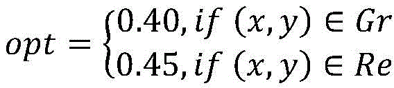
图8(1-4)、图8(2-4)和图8(3-4)是根据本发明实施例中的图8(1-3)、图8(2-3)和图8(3-3)缺口图像经过图像二值化后的缺口图像bw。Figure 8(1-4), Figure 8(2-4) and Figure 8(3-4) are Figure 8(1-3), Figure 8(2-3) and Figure 8( 3-3) The notch image is the notch image bw after image binarization.
下面结合图9和图10对本发明的步骤S5和步骤S6的可选实施例进行详细说明。Optional embodiments of step S5 and step S6 of the present invention will be described in detail below with reference to FIG. 9 and FIG. 10 .
图9是根据本发明实施例中的缺口检测及计算的流程图,如图9所示,该方法包括根据图像特征直线拟合算法提取缺口线的方程,计算缺口线的倾斜角度α0;当 |α0|>γ时,缺口图像的矫正角度α1=-α0,否则缺口图像的矫正角度α1=0,即不需要矫正;根据图像特征直线拟合算法提取倾斜矫正后的缺口图像的缺口线l1和基准线l2;根据缺口线l1和基准线l2计算缺口值w。Fig. 9 is a flow chart of notch detection and calculation according to an embodiment of the present invention. As shown in Fig. 9, the method includes extracting the equation of the notch line according to the image feature line fitting algorithm, and calculating the inclination angle α 0 of the notch line; When |α 0 |>γ, the correction angle of the notch image is α 1 =-α 0 , otherwise the correction angle of the notch image is α 1 =0, that is, correction is not required; the notch image after tilt correction is extracted according to the image feature line fitting algorithm The notch line l 1 and the reference line l 2 ; the gap value w is calculated according to the notch line l 1 and the reference line l 2 .
1.根据图像特征直线拟合算法提取缺口线的方程,计算缺口线的倾斜角度α0。对于图8(1-4),缺口线方程为:y=-0.0457x+211.5266,缺口线的倾斜角度α0=-2.6°,不需要进行倾斜矫正;对于图8(2-4),缺口线方程为:y=0.0425x+ 179.6897,缺口线的倾斜角度α0=-1.9°,不需要进行倾斜矫正;对于图8(3-4),缺口线方程为:y=0.1184x+170.5011缺口线的倾斜角度α0=-6.8°,需要进行倾斜矫正,矫正的角度α1=6.8°。图10(1-1)、图10(1-2)和图10(1-3)是根据本发明实施例中的图8(1-4)、图8(2-4)和图8(3-4)缺口图像经过图像倾斜检测及矫正后的缺口图像。1. Extract the equation of the notch line according to the image feature straight line fitting algorithm, and calculate the inclination angle α 0 of the notch line. For Fig. 8 (1-4), the notch line equation is: y=-0.0457x+211.5266, the inclination angle α 0 of the notch line =-2.6°, no tilt correction is required; for Fig. 8 (2-4), the notch The line equation is: y=0.0425x+179.6897, the inclination angle of the notch line α 0 =-1.9°, no need for inclination correction; for Figure 8 (3-4), the notch line equation is: y=0.1184x+170.5011 notch line The inclination angle α 0 =-6.8°, the inclination correction needs to be performed, and the corrected angle α 1 =6.8°. Figure 10(1-1), Figure 10(1-2) and Figure 10(1-3) are Figure 8(1-4), Figure 8(2-4) and Figure 8( 3-4) The notch image is the notch image after image tilt detection and correction.
2.根据图像特征直线拟合算法提取倾斜矫正后的缺口图像的缺口线l1和基准线l2。2. Extract the notch line l 1 and the reference line l 2 of the notch image after tilt correction according to the image feature line fitting algorithm.
对于图10(1-1):For Figure 10(1-1):
l1:y=-0.0457x+211.5266l 1 : y=-0.0457x+211.5266
l2:y=-0.0196x+194.0606l 2 : y=-0.0196x+194.0606
对于图10(1-2):For Figure 10(1-2):
l1:y=0.0425x+179.6897l 1 : y=0.0425x+179.6897
l2:y=-0.0328x+199.2366l 2 : y=-0.0328x+199.2366
对于图10(1-3):For Figure 10(1-3):
l1:y=-0.0047x+183.3433l 1 : y=-0.0047x+183.3433
l2:y=-0.0312x+192.5391l 2 : y=-0.0312x+192.5391
3.根据缺口线l1和基准线l2计算缺口值w。对于图10(1-1),缺口值w为-19,表示上缺口向右偏移19个像素;对于图10(1-2),缺口值w为-4,表示下缺口向右偏移4个像素;对于图10(1-3),缺口值w为-5,表示下缺口向右偏移5个像素。图10(2-1)、图10(2-2)和图10(2-3)是根据本发明实施例中的图10(1- 1)、图10(1-2)和图10(1-3)缺口图像经过图像缺口直线拟合及缺口大小计算后的结果。3. Calculate the gap value w according to the gap line l 1 and the reference line l 2 . For Figure 10(1-1), the gap value w is -19, which means that the upper gap is shifted to the right by 19 pixels; for Figure 10(1-2), the gap value w is -4, which means that the lower gap is shifted to the right 4 pixels; for Figure 10 (1-3), the notch value w is -5, which means that the lower notch is shifted to the right by 5 pixels. Figure 10(2-1), Figure 10(2-2) and Figure 10(2-3) are Figure 10(1-1), Figure 10(1-2) and Figure 10( 1-3) The gap image is the result of image gap linear fitting and gap size calculation.
经过所述步骤的处理,即可得到每一种转辙机的缺口大小及缺口的偏移方向,进而实时掌握转辙机缺口的状态。在缺口图像局部曝光过度、缺口图像倾斜时均能准确计算缺口值。在出现异常或故障情况时能够及时进行报警,便于相关部门进行应急处理和维修。Through the processing of the above steps, the size of the gap and the offset direction of the gap of each type of switch machine can be obtained, and then the state of the gap of the switch machine can be grasped in real time. The notch value can be accurately calculated when the notch image is partially overexposed or the notch image is tilted. In the event of an abnormality or failure, an alarm can be issued in time, which is convenient for relevant departments to carry out emergency treatment and maintenance.
上述描述仅是对本申请较佳实施例的描述,并非是对本申请范围的任何限定。任何熟悉该领域的普通技术人员根据上述揭示的技术内容做出的任何变更或修饰均应当视为等同的有效实施例,均属于本申请技术方案保护的范围。The above description is only a description of the preferred embodiments of the application, and is not intended to limit the scope of the application. Any change or modification made by any person familiar with the field based on the technical content disclosed above shall be regarded as an equivalent effective embodiment, and shall fall within the protection scope of the technical solution of the present application.
Claims (8)




Priority Applications (1)
| Application Number | Priority Date | Filing Date | Title |
|---|---|---|---|
| CN201910439304.0A CN110310255B (en) | 2019-05-24 | 2019-05-24 | Point switch notch detection method based on target detection and image processing |
Applications Claiming Priority (1)
| Application Number | Priority Date | Filing Date | Title |
|---|---|---|---|
| CN201910439304.0A CN110310255B (en) | 2019-05-24 | 2019-05-24 | Point switch notch detection method based on target detection and image processing |
Publications (2)
| Publication Number | Publication Date |
|---|---|
| CN110310255A CN110310255A (en) | 2019-10-08 |
| CN110310255B true CN110310255B (en) | 2023-01-10 |
Family
ID=68075299
Family Applications (1)
| Application Number | Title | Priority Date | Filing Date |
|---|---|---|---|
| CN201910439304.0A Active CN110310255B (en) | 2019-05-24 | 2019-05-24 | Point switch notch detection method based on target detection and image processing |
Country Status (1)
| Country | Link |
|---|---|
| CN (1) | CN110310255B (en) |
Families Citing this family (16)
| Publication number | Priority date | Publication date | Assignee | Title |
|---|---|---|---|---|
| CN110733048B (en) * | 2019-11-05 | 2021-03-26 | 广东博智林机器人有限公司 | Alignment supply robot and alignment method thereof |
| CN111145197B (en) * | 2019-12-10 | 2022-05-03 | 电子科技大学 | Accurate turnout switch machine notch edge positioning method based on histogram and local gradient |
| CN111127496B (en) * | 2019-12-10 | 2022-07-29 | 电子科技大学 | Turnout switch machine notch edge positioning method based on two-dimensional histogram and adaptive classification |
| CN111161294B (en) * | 2019-12-10 | 2021-12-03 | 电子科技大学 | Turnout switch machine gap detection method based on histogram and straight line fitting |
| CN111003022B (en) * | 2019-12-25 | 2021-11-30 | 中国铁道科学研究院集团有限公司通信信号研究所 | Magnetic grid measurement-based turnout operation overall process monitoring method and device |
| US12008743B2 (en) * | 2020-05-22 | 2024-06-11 | Robert Bosch Gmbh | Hazard detection ensemble architecture system and method |
| CN112580465A (en) * | 2020-12-08 | 2021-03-30 | 卡斯柯信号有限公司 | Switch overhaul evaluation method and system |
| CN112668484B (en) * | 2020-12-29 | 2023-04-21 | 上海工程技术大学 | Method for detecting access distance between dynamic and static nodes of automatic switch machine shutter |
| CN113553938B (en) * | 2021-07-19 | 2024-05-14 | 黑芝麻智能科技(上海)有限公司 | Seat belt detection method, apparatus, computer device, and storage medium |
| CN114359260B (en) * | 2022-01-18 | 2023-11-03 | 成都理工大学 | A method and device for detecting defects on the surface of cigarette rods |
| CN114529715B (en) * | 2022-04-22 | 2022-07-19 | 中科南京智能技术研究院 | Image identification method and system based on edge extraction |
| CN114913151A (en) * | 2022-05-12 | 2022-08-16 | 深圳市迈进科技有限公司 | Point switch notch image detection method based on artificial intelligence AI model |
| CN115565124B (en) * | 2022-08-23 | 2026-01-02 | 上海建工集团股份有限公司 | A Deep Learning-Based Method for Excavator Working Status Recognition |
| CN115359449B (en) * | 2022-10-18 | 2023-01-24 | 济南铁路天龙高新技术开发有限公司 | Automatic identification method and system for turnout notch image of point switch |
| CN117011781A (en) * | 2023-06-30 | 2023-11-07 | 成都唐源电气股份有限公司 | Neural network based outdoor equipment monitoring method and device for turnout |
| CN120765603A (en) * | 2025-07-02 | 2025-10-10 | 江汉大学 | Dynamic detection method of switch gap based on instance segmentation processing of deep learning |
Citations (6)
| Publication number | Priority date | Publication date | Assignee | Title |
|---|---|---|---|---|
| CN102556119A (en) * | 2011-12-19 | 2012-07-11 | 济南铁路天龙高新技术开发有限公司 | Method for directly collecting gap data measured by indication lever gap image of railway point switch |
| CN107578410A (en) * | 2017-04-26 | 2018-01-12 | 济南铁路天龙高新技术开发有限公司 | Notch of switch machine automatic distinguishing method for image |
| CN108038853A (en) * | 2017-12-18 | 2018-05-15 | 浙江工业大学 | Ceramic tile surface defect identification method based on convolutional neural network and active learning |
| CN108573283A (en) * | 2018-04-12 | 2018-09-25 | 大连理工大学 | A design method for point machine gap monitoring and anti-missing report |
| CN109064461A (en) * | 2018-08-06 | 2018-12-21 | 长沙理工大学 | A kind of detection method of surface flaw of steel rail based on deep learning network |
| CN109583295A (en) * | 2018-10-19 | 2019-04-05 | 河南辉煌科技股份有限公司 | A kind of notch of switch machine automatic testing method based on convolutional neural networks |
-
2019
- 2019-05-24 CN CN201910439304.0A patent/CN110310255B/en active Active
Patent Citations (6)
| Publication number | Priority date | Publication date | Assignee | Title |
|---|---|---|---|---|
| CN102556119A (en) * | 2011-12-19 | 2012-07-11 | 济南铁路天龙高新技术开发有限公司 | Method for directly collecting gap data measured by indication lever gap image of railway point switch |
| CN107578410A (en) * | 2017-04-26 | 2018-01-12 | 济南铁路天龙高新技术开发有限公司 | Notch of switch machine automatic distinguishing method for image |
| CN108038853A (en) * | 2017-12-18 | 2018-05-15 | 浙江工业大学 | Ceramic tile surface defect identification method based on convolutional neural network and active learning |
| CN108573283A (en) * | 2018-04-12 | 2018-09-25 | 大连理工大学 | A design method for point machine gap monitoring and anti-missing report |
| CN109064461A (en) * | 2018-08-06 | 2018-12-21 | 长沙理工大学 | A kind of detection method of surface flaw of steel rail based on deep learning network |
| CN109583295A (en) * | 2018-10-19 | 2019-04-05 | 河南辉煌科技股份有限公司 | A kind of notch of switch machine automatic testing method based on convolutional neural networks |
Non-Patent Citations (1)
| Title |
|---|
| 基于视频监控的转辙机缺口监测系统设计;程龙等;《铁道通信信号》;20161031;全文 * |
Also Published As
| Publication number | Publication date |
|---|---|
| CN110310255A (en) | 2019-10-08 |
Similar Documents
| Publication | Publication Date | Title |
|---|---|---|
| CN110310255B (en) | Point switch notch detection method based on target detection and image processing | |
| CN113516660B (en) | Visual positioning and defect detection method and device suitable for train | |
| CN112434695B (en) | Upper pull rod fault detection method based on deep learning | |
| CN110363742B (en) | Point switch notch detection method based on CNN and image processing | |
| CN111079747B (en) | Railway wagon bogie side frame fracture fault image identification method | |
| CN106919915B (en) | Map road marking and road quality acquisition device and method based on ADAS system | |
| CN111260615B (en) | Laser and machine vision fusion-based method for detecting apparent diseases of unmanned aerial vehicle bridge | |
| CN103150549B (en) | A kind of road tunnel fire detection method based on the early stage motion feature of smog | |
| CN102902974B (en) | Image based method for identifying railway overhead-contact system bolt support identifying information | |
| CN116665011A (en) | A machine vision-based method for identifying foreign objects in coal flow of coal mine belt conveyors | |
| CN114331986A (en) | A method of dam crack identification and measurement based on unmanned aerial vehicle vision | |
| CN110111303A (en) | A kind of large-scale carrier strip tearing intelligent fault detection method based on dynamic image | |
| CN109489724B (en) | A kind of comprehensive detection device and detection method for safe running environment of tunnel train | |
| CN105203552A (en) | 360-degree tread image detecting system and method | |
| CN111626169B (en) | Image-based railway dangerous falling rock size judgment method | |
| CN115294541A (en) | A Local Feature Enhanced Transformer Road Crack Detection Method | |
| CN107895492A (en) | A kind of express highway intelligent analysis method based on conventional video | |
| CN114772208A (en) | Non-contact belt tearing detection system and method based on image segmentation | |
| CN103150550B (en) | A kind of road pedestrian event detection method based on gripper path analysis | |
| CN113240682B (en) | Overturn-preventing construction driving map generation method and system for crawler crane | |
| Zheng et al. | Rail detection based on LSD and the least square curve fitting | |
| Zhao et al. | Image-based comprehensive maintenance and inspection method for bridges using deep learning | |
| CN109146859A (en) | A kind of pavement crack detection system based on machine vision | |
| KR102585146B1 (en) | Pothole detection device and method based on deep learning | |
| CN115761468A (en) | A water level detection system and method based on image segmentation and target detection technology |
Legal Events
| Date | Code | Title | Description |
|---|---|---|---|
| PB01 | Publication | ||
| PB01 | Publication | ||
| SE01 | Entry into force of request for substantive examination | ||
| SE01 | Entry into force of request for substantive examination | ||
| GR01 | Patent grant | ||
| GR01 | Patent grant |