CN110260279B - Luminaire wiring devices and lamps - Google Patents

Luminaire wiring devices and lamps Download PDF

Info

Publication number
CN110260279B
CN110260279B CN201910380763.6A CN201910380763A CN110260279B CN 110260279 B CN110260279 B CN 110260279B CN 201910380763 A CN201910380763 A CN 201910380763A CN 110260279 B CN110260279 B CN 110260279B
Authority
CN
China
Prior art keywords
lamp
contact pin
top cover
contact
wiring device
Prior art date
Legal status (The legal status is an assumption and is not a legal conclusion. Google has not performed a legal analysis and makes no representation as to the accuracy of the status listed.)
Active
Application number
CN201910380763.6A
Other languages
Chinese (zh)
Other versions
CN110260279A (en
Inventor
周明杰
杨小鹏
Current Assignee (The listed assignees may be inaccurate. Google has not performed a legal analysis and makes no representation or warranty as to the accuracy of the list.)
Oceans King Lighting Science and Technology Co Ltd
Oceans King Dongguan Lighting Technology Co Ltd
Shenzhen Oceans King Lighting Engineering Co Ltd
Original Assignee
Oceans King Lighting Science and Technology Co Ltd
Oceans King Dongguan Lighting Technology Co Ltd
Shenzhen Oceans King Lighting Engineering Co Ltd
Priority date (The priority date is an assumption and is not a legal conclusion. Google has not performed a legal analysis and makes no representation as to the accuracy of the date listed.)
Filing date
Publication date
Application filed by Oceans King Lighting Science and Technology Co Ltd, Oceans King Dongguan Lighting Technology Co Ltd, Shenzhen Oceans King Lighting Engineering Co Ltd filed Critical Oceans King Lighting Science and Technology Co Ltd
Priority to CN201910380763.6A priority Critical patent/CN110260279B/en
Publication of CN110260279A publication Critical patent/CN110260279A/en
Application granted granted Critical
Publication of CN110260279B publication Critical patent/CN110260279B/en
Active legal-status Critical Current
Anticipated expiration legal-status Critical

Links

Images

Classifications

    • FMECHANICAL ENGINEERING; LIGHTING; HEATING; WEAPONS; BLASTING
    • F21LIGHTING
    • F21VFUNCTIONAL FEATURES OR DETAILS OF LIGHTING DEVICES OR SYSTEMS THEREOF; STRUCTURAL COMBINATIONS OF LIGHTING DEVICES WITH OTHER ARTICLES, NOT OTHERWISE PROVIDED FOR
    • F21V23/00Arrangement of electric circuit elements in or on lighting devices
    • F21V23/06Arrangement of electric circuit elements in or on lighting devices the elements being coupling devices, e.g. connectors

Landscapes

  • Engineering & Computer Science (AREA)
  • General Engineering & Computer Science (AREA)
  • Arrangement Of Elements, Cooling, Sealing, Or The Like Of Lighting Devices (AREA)
  • Non-Portable Lighting Devices Or Systems Thereof (AREA)

Abstract

The invention belongs to the technical field of lamps, and particularly relates to a lamp wiring device and a lamp, wherein the lamp wiring device comprises a lamp joint and a top cover, the lamp joint is provided with an installation cavity with an opening, and the top cover is arranged on the lamp joint and seals the opening of the installation cavity; a fixed seat and a wire holder used for being connected with an external part are arranged in the mounting cavity, an electrical connecting piece is arranged on the fixed seat, and the electrical connecting piece is electrically connected with the wire holder; be equipped with the contact pin that is used for with the light emitting component electric connection of lamps and lanterns on the top cap, the contact pin all is located the installation intracavity, and the first end of contact pin is installed in the top cap, and the second end of contact pin stretches out outside the top cap and with electric connection spare electric connection. This lamps and lanterns termination through contact pilotage and electric connection contact, makes its inside automatic switch on, so, has saved the trouble of carrying out the wiring in the installation cavity that lamps and lanterns connect, easy operation need not to relapse the dismouting, and the packaging efficiency is high, and the stability of wiring is good, and the wiring is efficient.

Description

灯具接线装置及灯具Luminaire wiring devices and lamps

技术领域technical field

本发明属于灯具技术领域,尤其涉及一种灯具接线装置及灯具。The invention belongs to the technical field of lamps, and in particular relates to a lamp wiring device and a lamp.

背景技术Background technique

现有的灯具一般作为照明灯具使用时,灯具的接线装置一般包括用于外部电线穿设的灯具接头和封住灯具接头内腔的顶盖,灯具接头的内腔内和顶盖上均设有电性部件,这些电性部件在灯具接头和顶盖安装之前需要通过连接导线连接,以确保灯具内部的电路导通,然后再将灯具接头和顶盖组装在一起,但在实际的接线过程中,在灯具接头内部进行接线操作复杂,并且,在灯具接头和顶盖的组装过程中,电性部件与连接导线的连接处因受到拉扯而松动甚至断路,也不得不反复拆装,该种接线方式无法有效地保证接线的稳定性且操作繁琐,组装效率低。When the existing lamps are generally used as lighting lamps, the wiring devices of the lamps generally include a lamp joint for external wires and a top cover to seal the inner cavity of the lamp joint. Electrical parts, these electrical parts need to be connected by connecting wires before the lamp joint and the top cover are installed to ensure that the circuit inside the lamp is connected, and then the lamp joint and the top cover are assembled together, but in the actual wiring process , The wiring operation inside the lamp connector is complicated, and during the assembly process of the lamp connector and the top cover, the connection between the electrical components and the connecting wire is loosened or even broken due to pulling, and has to be disassembled repeatedly. The method cannot effectively guarantee the stability of the wiring, the operation is cumbersome, and the assembly efficiency is low.

发明内容SUMMARY OF THE INVENTION

本发明的目的在于提供一种灯具接线装置及灯具,旨在解决现有技术中的灯具接线装置内部接线操作繁琐而导致组装效率低技术问题。The purpose of the present invention is to provide a lamp wiring device and a lamp, which aim to solve the technical problem of low assembly efficiency caused by complicated internal wiring operations of the lamp wiring device in the prior art.

为实现上述目的,本发明采用的技术方案是:一种灯具接线装置,包括灯具接头和顶盖,所述灯具接头开设有具有开口的安装腔,所述顶盖安装于所述灯具接头上并封住所述安装腔的开口;所述安装腔内设有固定座和用于与外部部件连接的接线座,所述固定座上设有电性连接件,所述电性连接件与所述接线座电性连接;所述顶盖上设有用于与灯具的发光组件电性连接的触针,所述触针均位于所述安装腔内,所述触针的第一端安装于所述顶盖内,所述触针的第二端伸出所述顶盖外并与所述电性连接件电性连接。In order to achieve the above object, the technical solution adopted in the present invention is: a lamp wiring device, comprising a lamp joint and a top cover, the lamp joint is provided with an installation cavity with an opening, and the top cover is mounted on the lamp joint and The opening of the installation cavity is sealed; the installation cavity is provided with a fixed seat and a wiring seat used for connecting with external components, and an electrical connector is arranged on the fixed seat, and the electrical connector is connected with the The wiring socket is electrically connected; the top cover is provided with contact pins for electrical connection with the light-emitting component of the lamp, the contact pins are all located in the installation cavity, and the first ends of the contact pins are mounted on the Inside the top cover, the second ends of the contact pins protrude out of the top cover and are electrically connected with the electrical connector.

进一步地,所述顶盖上还设有触针座和用于与灯具的发光部件连接的OT端子,所述触针座内部设有安装孔,所述触针穿设于所述安装孔内,所述触针的第一端位于所述安装孔内并与所述OT端子电性连接,所述触针的第二端伸出所述安装孔外。Further, the top cover is also provided with a contact pin seat and an OT terminal for connecting with the light-emitting component of the lamp, the contact pin seat is provided with a mounting hole inside, and the contact pin is penetrated in the mounting hole , the first end of the contact pin is located in the mounting hole and is electrically connected with the OT terminal, and the second end of the contact pin extends out of the mounting hole.

进一步地,所述安装孔包括大孔直径段和小孔直径段,所述触针的第一端的外周壁上设有限位凸缘,所述限位凸缘位于所述大孔直径段内,所述触针的第二端伸出所述小孔直径段。Further, the mounting hole includes a large hole diameter section and a small hole diameter section, a limit flange is provided on the outer peripheral wall of the first end of the contact pin, and the limit flange is located in the large hole diameter section. , the second end of the contact pin protrudes out of the diameter section of the small hole.

进一步地,所述灯具接线装置还包括弹簧和弹簧压片,所述弹簧套设于所述触针的第一端上,所述弹簧压片通过螺钉固定安装于所述触针座上并封住所述大孔直径段的开口,所述弹簧位于所述限位凸缘和所述弹簧压片之间。Further, the lamp wiring device further includes a spring and a spring pressing piece, the spring is sleeved on the first end of the contact pin, and the spring pressing piece is fixedly installed on the contact pin seat by screws and sealed. The spring is located between the limiting flange and the spring pressing piece to cover the opening of the large hole diameter section.

进一步地,所述电性连接件为铜柱或者铜环。Further, the electrical connector is a copper column or a copper ring.

进一步地,所述固定座背向所述顶盖的侧面上设有电路板,所述接线柱安装于所述电路板上,所述固定座上设有穿设孔;所述铜柱穿过所述穿设孔后与所述电路板电性连接;或者,所述铜环上设有朝向所述铜环侧面弯折延伸的接线凸起,所述铜环安装于所述固定座朝向所述顶盖的表面上,所述接线凸起穿过所述穿设孔后与所述电路板电性连接。Further, a circuit board is provided on the side of the fixing seat facing away from the top cover, the wiring post is mounted on the circuit board, and a through hole is formed on the fixing seat; the copper post passes through The through hole is electrically connected to the circuit board; or, the copper ring is provided with a wiring protrusion that bends and extends toward the side of the copper ring, and the copper ring is installed on the fixing seat and faces the On the surface of the top cover, the wiring protrusions are electrically connected to the circuit board after passing through the through holes.

进一步地,所述顶盖上设有圆环凸起,所述圆环凸起的外周壁上设有外螺纹,所述安装腔的内周壁上设有内螺纹,所述外螺纹和所述内螺纹螺纹配合连接。Further, the top cover is provided with an annular protrusion, the outer peripheral wall of the annular protrusion is provided with an external thread, the inner peripheral wall of the installation cavity is provided with an internal thread, and the external thread and the Internally threaded connection.

进一步地,所述灯具接线装置包括密封圈,所述圆环凸起的外周壁上设有密封凹槽,所述密封圈套设于所述圆环凸起外并位于所述密封凹槽内,所述密封圈夹持于所述圆环凸起和所述安装腔的内周壁之间。Further, the lamp wiring device includes a sealing ring, a sealing groove is formed on the outer peripheral wall of the annular protrusion, and the sealing ring is sleeved outside the annular protrusion and located in the sealing groove, The sealing ring is clamped between the annular protrusion and the inner peripheral wall of the installation cavity.

进一步地,所述灯具接线装置还包括卡簧,所述固定座的圆周处设有固定凸缘,所述固定凸缘通过螺钉固定安装于所述安装腔的内壁面上,所述安装腔的内周壁上设有环状凹槽,所述卡簧卡入所述环状凹槽内,所述卡簧的侧面正对所述固定凸缘朝向所述顶盖的侧面设置。Further, the lamp wiring device further includes a retaining ring, a fixing flange is provided at the circumference of the fixing seat, and the fixing flange is fixedly installed on the inner wall surface of the installation cavity by screws. An annular groove is arranged on the inner peripheral wall, the retaining spring is clamped into the annular groove, and the side surface of the retaining spring is disposed facing the side surface of the fixing flange and facing the top cover.

本发明提供的灯具接线装置中的上述一个或多个技术方案至少具有如下技术效果之一:在组装时,将顶盖直接在安装灯具接头上后,顶盖上的触针的第二端直接与灯具接头上的固定座上的电性连接件接触导通,由于电性接触件和接线座电性连接,如此,可以实现灯具接头内部的接线座与顶盖上的触针上的电性导通,省去了在灯具接头的安装腔内进行接线的麻烦,操作简单,无需反复拆装,组装效率高,且接线的稳定性好,接线效率高。The above one or more technical solutions in the lamp wiring device provided by the present invention have at least one of the following technical effects: during assembly, after the top cover is directly installed on the lamp connector, the second ends of the contact pins on the top cover directly It is in contact with the electrical connector on the fixed seat on the lamp connector. Since the electrical contact is electrically connected with the wiring seat, it is possible to realize the electrical connection between the wiring seat inside the lamp connector and the contact pin on the top cover. Conduction, eliminating the trouble of wiring in the installation cavity of the lamp connector, simple operation, no need for repeated disassembly and assembly, high assembly efficiency, good wiring stability, and high wiring efficiency.

本发明的另一个技术方案是:一种灯具,包括发光组件和上述灯具接线装置,所述发光组件安装于所述顶盖的外侧,所述发光组件与所述触针电性连接。Another technical solution of the present invention is: a lamp, comprising a light-emitting component and the above-mentioned lamp wiring device, the light-emitting component is mounted on the outer side of the top cover, and the light-emitting component is electrically connected with the contact pins.

本发明实施例的灯具,采用了上述的灯具接线装置,在组装时,先将顶盖直接在安装灯具接头上后,顶盖上的触针的第二端直接与灯具接头上的固定座上的电性连接件接触导通,然后再发光组件安装在顶盖上并将发光组件与触针电性连接,由于电性接触件和接线座电性连接,如此,可以实现灯具接头内部的接线座与灯具的反光组件的电性导通,省去了在灯具接头的安装腔内进行接线的麻烦,操作简单,无需反复拆装,组装效率高,且接线的稳定性好,接线效率高。The lamp of the embodiment of the present invention adopts the above-mentioned lamp wiring device. When assembling, the top cover is directly installed on the lamp connector, and the second end of the contact pin on the top cover is directly connected to the fixing seat on the lamp connector. The electrical connector of the luminaire is in contact and conducts, and then the light-emitting component is installed on the top cover and the light-emitting component is electrically connected to the contact pin. Since the electrical contact piece and the wiring seat are electrically connected, the wiring inside the lamp connector can be realized. The electrical connection between the base and the reflective component of the lamp saves the trouble of wiring in the installation cavity of the lamp connector, the operation is simple, the repeated disassembly and assembly are not required, the assembly efficiency is high, the wiring stability is good, and the wiring efficiency is high.

附图说明Description of drawings

为了更清楚地说明本发明实施例中的技术方案,下面将对实施例或现有技术描述中所需要使用的附图作简单地介绍,显而易见地,下面描述中的附图仅仅是本发明的一些实施例,对于本领域普通技术人员来讲,在不付出创造性劳动性的前提下,还可以根据这些附图获得其他的附图。In order to explain the technical solutions in the embodiments of the present invention more clearly, the following briefly introduces the accompanying drawings that need to be used in the description of the embodiments or the prior art. Obviously, the drawings in the following description are only for the present invention. In some embodiments, for those of ordinary skill in the art, other drawings can also be obtained according to these drawings without any creative effort.

图1为本发明实施例提供的灯具的正视图。FIG. 1 is a front view of a lamp provided by an embodiment of the present invention.

图2为本发明实施例提供的灯具的俯视图。FIG. 2 is a top view of a lamp provided by an embodiment of the present invention.

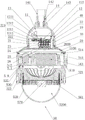
图3为沿图1中C-C线的剖切视图。FIG. 3 is a cross-sectional view taken along line C-C in FIG. 1 .

图4为沿图2中D-D线的剖切视图。FIG. 4 is a cross-sectional view taken along line D-D in FIG. 2 .

图5为图4中G处的局部放大图。FIG. 5 is a partial enlarged view of G in FIG. 4 .

图6为图4中H处的局部放大图。FIG. 6 is a partial enlarged view of H in FIG. 4 .

图7为图4中I处的局部放大图。FIG. 7 is a partial enlarged view of I in FIG. 4 .

图8为图4中J处的局部放大图。FIG. 8 is a partial enlarged view of J in FIG. 4 .

图9为本发明实施例提供的灯具的发光组件的结构示意图。FIG. 9 is a schematic structural diagram of a light-emitting component of a lamp provided by an embodiment of the present invention.

图10为本发明实施例提供的灯具的爆炸图。FIG. 10 is an exploded view of a lamp provided by an embodiment of the present invention.

其中,图中各附图标记:Among them, each reference sign in the figure:

10—灯具接头 11—安装腔 12—固定座10—lamp connector 11—installation cavity 12—fixed seat

13—接线座 14—通孔 20—顶盖13—Terminal Block 14—Through Hole 20—Top Cover

21—触针 22—触针座 23—OT端子21—contact pin 22—contact pin holder 23—OT terminal

24—弹簧 25—弹簧压片 26—螺钉24—spring 25—spring pressure piece 26—screws

27—圆环凸起 28—穿线孔 29—外接地螺钉27—Ring protrusion 28—Thread hole 29—External grounding screw

30—密封圈 40—卡簧 50—发光组件30—sealing ring 40—circlip 50—light-emitting components

111—环状凹槽 112—内接地螺钉 121—电性连接件111—Annular groove 112—Internal grounding screw 121—Electrical connector

122—电路板 123—穿设孔 124—固定凸缘122—Circuit board 123—Through hole 124—Fixing flange

141—压紧螺母 142—垫圈 143—填料141—compression nut 142—washer 143—packing

200—第一环形槽 211—限位凸缘 221—安装孔200—first annular groove 211—limiting flange 221—installation hole

222—穿线槽 231—连接孔 232—连接导线222—threading slot 231—connecting hole 232—connecting wire

271—密封凹槽 281—密封接头 282—密封封胶挡圈271—Sealing groove 281—Sealing joint 282—Sealing gasket

510—驱动壳 511—螺丝 512—第一导线孔510—Driver shell 511—Screw 512—First wire hole

513—散热片 514—环形密封垫片 515—第一环形凸起513—heat sink 514—ring sealing gasket 515—first annular protrusion

516—第二环形凸起 517—第三环形凸起 518—固定孔516—Second annular protrusion 517—Third annular protrusion 518—Fixing hole

520—透明罩 521—第二密封圈 522—第二环形槽520—Transparent cover 521—Second sealing ring 522—Second annular groove

523—压圈 524—夹紧凸缘 530—光源壳523—Pressing ring 524—Clamping flange 530—Light source housing

531—固定柱 532—连接柱 540—驱动装置531—fixed post 532—connected post 540—drive device

541—导线 542—电源 543—封装型驱动件541—Wire 542—Power 543—Encapsulated Driver

544—U型架 545—输入接线端子 546—输出接线端子544—U-shaped frame 545—Input wiring terminal 546—Output wiring terminal

550—隔爆接头组件 551—隔爆接头 552—第一密封圈550—flameproof joint assembly 551—flameproof joint 552—first sealing ring

553—封胶挡圈 554—密封胶 560—光源553—Sealant retaining ring 554—Sealant 560—Light source

561—灯板 562—灯珠 570—模块封装件561—lamp board 562—lamp beads 570—module package

580—限位件 2000—隔板 2211—大孔直径段580—limiting piece 2000—partition plate 2211—large hole diameter section

2212—小孔直径段 1211—铜柱 1212—铜环2212—small hole diameter section 1211—copper column 1212—copper ring

5100—驱动腔 5200—光源腔 5231—环状沉台5100—drive cavity 5200—light source cavity 5231—ring-shaped sink

5321—第二导线孔 5322—第三环形槽 5323—第三密封圈5321—the second wire hole 5322—the third annular groove 5323—the third sealing ring

5511—接头头部 5512—接头尾部 5513—第三导线孔5511—connector head 5512—connector tail 5513—third wire hole

12121—接线凸起 53211—阶梯面。12121—connection bump 53211—step surface.

具体实施方式Detailed ways

下面详细描述本发明的实施例,所述实施例的示例在附图中示出,其中自始至终相同或类似的标号表示相同或类似的元件或具有相同或类似功能的元件。下面通过参考附图1~10描述的实施例是示例性的,旨在用于解释本发明,而不能理解为对本发明的限制。The following describes in detail the embodiments of the present invention, examples of which are illustrated in the accompanying drawings, wherein the same or similar reference numerals refer to the same or similar elements or elements having the same or similar functions throughout. The embodiments described below with reference to FIGS. 1 to 10 are exemplary, and are intended to be used to explain the present invention, but should not be construed as a limitation of the present invention.

在本发明的描述中,需要理解的是,术语“长度”、“宽度”、“上”、“下”、“前”、“后”、“左”、“右”、“竖直”、“水平”、“顶”、“底”“内”、“外”等指示的方位或位置关系为基于附图所示的方位或位置关系,仅是为了便于描述本发明和简化描述,而不是指示或暗示所指的装置或元件必须具有特定的方位、以特定的方位构造和操作,因此不能理解为对本发明的限制。In the description of the present invention, it should be understood that the terms "length", "width", "upper", "lower", "front", "rear", "left", "right", "vertical", The orientations or positional relationships indicated by "horizontal", "top", "bottom", "inside", "outside", etc. are based on the orientations or positional relationships shown in the accompanying drawings, which are only for the convenience of describing the present invention and simplifying the description, rather than An indication or implication that the referred device or element must have a particular orientation, be constructed and operate in a particular orientation, is not to be construed as a limitation of the invention.

此外,术语“第一”、“第二”仅用于描述目的,而不能理解为指示或暗示相对重要性或者隐含指明所指示的技术特征的数量。由此,限定有“第一”、“第二”的特征可以明示或者隐含地包括一个或者更多个该特征。在本发明的描述中,“多个”的含义是两个或两个以上,除非另有明确具体的限定。In addition, the terms "first" and "second" are only used for descriptive purposes, and should not be construed as indicating or implying relative importance or implying the number of indicated technical features. Thus, a feature defined as "first" or "second" may expressly or implicitly include one or more of that feature. In the description of the present invention, "plurality" means two or more, unless otherwise expressly and specifically defined.

在本发明中,除非另有明确的规定和限定,术语“安装”、“相连”、“连接”、“固定”等术语应做广义理解,例如,可以是固定连接,也可以是可拆卸连接,或成一体;可以是机械连接,也可以是电连接;可以是直接相连,也可以通过中间媒介间接相连,可以是两个元件内部的连通或两个元件的相互作用关系。对于本领域的普通技术人员而言,可以根据具体情况理解上述术语在本发明中的具体含义。In the present invention, unless otherwise expressly specified and limited, the terms "installed", "connected", "connected", "fixed" and other terms should be understood in a broad sense, for example, it may be a fixed connection or a detachable connection , or integrated; it can be a mechanical connection or an electrical connection; it can be a direct connection or an indirect connection through an intermediate medium, and it can be the internal connection of the two elements or the interaction relationship between the two elements. For those of ordinary skill in the art, the specific meanings of the above terms in the present invention can be understood according to specific situations.

如图1~10所示,在本发明的一个实施例中,提供一种灯具接线装置,主要应用于炼化装置区内的照明灯具上,该灯具接线装置包括灯具接头10和顶盖20,灯具接头10开设有具有开口的安装腔11,顶盖20安装于灯具接头10上并封住安装腔11的开口;安装腔11内设有固定座12和用于与外部部件连接的接线座13,固定座12上设有电性连接件121,电性连接件121与接线座13电性连接;其中,灯具接头10上设有与安装腔11相通的通孔14,外部电源线穿过通孔14后与接线座13连接为灯具提供电力;固定座12起到支撑固定电性连接件121的作用;进一步地,顶盖20上设有用于与灯具的发光组件50电性连接的触针21,触针21均位于安装腔11内,触针21的第一端安装于顶盖20内,触针21的第二端伸出顶盖20外并与电性连接件121电性连接;其中,触针21的第一端与安装在顶盖20上的发光组件50电性连接,通过触针21和电性连接件121的电性导通作用,从而将接线座13与发光组件50导通,进而为发光组件50提供电力支持,保证发光组件50的正常发光照明。As shown in FIGS. 1-10 , in one embodiment of the present invention, a lamp wiring device is provided, which is mainly applied to lighting lamps in the refining and chemical plant area. The lamp wiring device includes a lamp connector 10 and a top cover 20 . The lamp joint 10 is provided with an installation cavity 11 with an opening, and the top cover 20 is installed on the lamp joint 10 and seals the opening of the installation cavity 11; the installation cavity 11 is provided with a fixing seat 12 and a wiring seat 13 for connecting with external components , the fixing base 12 is provided with an electrical connector 121, and the electrical connector 121 is electrically connected with the wiring seat 13; wherein, the lamp connector 10 is provided with a through hole 14 that communicates with the installation cavity 11, and the external power line passes through the through hole 14. The hole 14 is connected to the wiring seat 13 to provide power for the lamp; the fixing seat 12 plays the role of supporting and fixing the electrical connector 121; further, the top cover 20 is provided with a contact pin for electrical connection with the light-emitting component 50 of the lamp 21. The contact pins 21 are all located in the installation cavity 11, the first ends of the contact pins 21 are installed in the top cover 20, and the second ends of the contact pins 21 extend out of the top cover 20 and are electrically connected with the electrical connector 121; The first end of the contact pin 21 is electrically connected to the light-emitting component 50 installed on the top cover 20 , and the connection base 13 and the light-emitting component 50 are electrically connected through the electrical conduction between the contact pin 21 and the electrical connector 121 . It is turned on, thereby providing power support for the light emitting assembly 50 to ensure the normal lighting of the light emitting assembly 50 .

具体地,本发明实施例的灯具接线装置,在组装时,将顶盖20直接在安装灯具接头10上后,顶盖20上的触针21的第二端直接与灯具接头10上的固定座12上的电性连接件121接触导通,由于电性接触件和接线座13电性连接,如此,可以实现灯具接头10内部的接线座13与顶盖20上的触针21上的电性导通,省去了在灯具接头10的安装腔11内进行接线的麻烦,操作简单,无需反复拆装,组装效率高,且接线的稳定性好,接线效率高。Specifically, when assembling the lamp wiring device according to the embodiment of the present invention, after the top cover 20 is directly installed on the lamp connector 10 , the second end of the contact pins 21 on the top cover 20 is directly connected to the fixing seat on the lamp connector 10 . The electrical connector 121 on the 12 is in contact and conduction. Since the electrical contact is electrically connected to the wiring seat 13, the electrical connection between the wiring seat 13 inside the lamp connector 10 and the contact pins 21 on the top cover 20 can be realized. Conduction, eliminating the trouble of wiring in the installation cavity 11 of the lamp connector 10, simple operation, no need for repeated disassembly and assembly, high assembly efficiency, good wiring stability, and high wiring efficiency.

进一步地,通孔14先将电源线穿过然后在通孔14与电源线之间填满填料143,以增加安装腔11的密封性以及该灯具接线装置的防爆性,然后再在电源线上依次套设有垫圈142和压紧螺母141,压紧螺母141螺纹连接于通孔14内并将垫圈142压紧填料143,进一步地增加该灯具接线装置的密封性和防爆性。Further, the power cable is passed through the through hole 14 and then the filler 143 is filled between the through hole 14 and the power cable to increase the sealing performance of the installation cavity 11 and the explosion-proof property of the lamp wiring device, and then the power cable is installed. A washer 142 and a compression nut 141 are sequentially sleeved, and the compression nut 141 is screwed into the through hole 14 and presses the washer 142 against the packing 143, further increasing the sealing and explosion-proof properties of the lamp wiring device.

进一步地,安装腔11内还设有内接地螺钉112,顶盖20的外侧还设有外接地螺钉29,以提高该灯具接线装置使用的安全性。Further, the installation cavity 11 is also provided with an inner ground screw 112, and the outer side of the top cover 20 is also provided with an external ground screw 29, so as to improve the safety of the lamp wiring device.

参阅图3、图4和图10所示,在本发明的另一个实施例中,提供的该灯具接线装置的顶盖20上还设有触针座22和用于与灯具的发光部件连接的OT端子23,触针座22内部设有安装孔221,触针21穿设于安装孔221内,触针21的第一端位于安装孔221内并与OT端子23电性连接,触针21的第二端伸出安装孔221外。具体地,触针21安装在触针座22的安装孔221内,安装孔221对触针21起到限位的作用,避免触针21在安装腔11内晃动,确保触针21与电性连接件121之间的稳定接触,避免接线装置出现短路的情况;另外,触针21的第二端伸出安装孔221外与电性连接件121相接触,从而实现电性导通;触针座22起到支撑固定触针21的作用;其中,OT端子23的头部设有连接孔231,触针21的第一端穿过连接孔231并与连接孔231固定连接,这样可以实现OT端子23与触针21的电性导通,并且,顶盖20设有与安装孔221相通的穿线槽222,触针座22上设有穿线孔28,OT端子23的尾部的连接导线232依次穿过触针座22上的穿线槽222和顶盖20上的穿线孔28后与发光组件50电性连接,如此,可以将位于安装腔11内部的触针21和位于安装腔11外侧的发光组件50电性导通,且OT端子23的连接操作简单,进一步简化了灯具的组装操作。Referring to Fig. 3, Fig. 4 and Fig. 10, in another embodiment of the present invention, the top cover 20 of the lamp wiring device is provided with a contact pin seat 22 and a contact pin seat 22 for connecting with the light-emitting component of the lamp. For the OT terminal 23, a mounting hole 221 is provided inside the contact pin holder 22. The contact pin 21 passes through the mounting hole 221. The first end of the contact pin 21 is located in the mounting hole 221 and is electrically connected to the OT terminal 23. The contact pin 21 The second end protrudes out of the mounting hole 221 . Specifically, the contact pin 21 is installed in the mounting hole 221 of the contact pin holder 22 , and the mounting hole 221 acts as a limiter for the contact pin 21 to prevent the contact pin 21 from shaking in the mounting cavity 11 , and to ensure the electrical connection between the contact pin 21 and the electrical property. The stable contact between the connecting pieces 121 avoids the short circuit of the wiring device; in addition, the second end of the contact pin 21 extends out of the mounting hole 221 to contact the electrical connecting piece 121, thereby realizing electrical conduction; the contact pin The seat 22 plays the role of supporting and fixing the contact pin 21; wherein, the head of the OT terminal 23 is provided with a connection hole 231, and the first end of the contact pin 21 passes through the connection hole 231 and is fixedly connected with the connection hole 231, so that the OT can be realized The terminal 23 is electrically connected to the contact pin 21 , and the top cover 20 is provided with a threading slot 222 communicating with the mounting hole 221 , the contact pin seat 22 is provided with a threading hole 28 , and the connecting wires 232 at the tail of the OT terminal 23 are arranged in sequence. After passing through the threading groove 222 on the contact pin holder 22 and the threading hole 28 on the top cover 20, it is electrically connected to the light-emitting component 50. In this way, the contact pins 21 located inside the mounting cavity 11 and the light-emitting components located outside the mounting cavity 11 can be connected. The component 50 is electrically connected, and the connection operation of the OT terminal 23 is simple, which further simplifies the assembly operation of the lamp.

进一步地,参阅图4所示,穿线孔28内设有套设于连接导线232上密封接头281,且密封接头281与连接导线232之间填满填料143,密封接头281的端部还设有密封封胶挡圈282,提高该灯具接线装置的密封性和隔爆性能。Further, as shown in FIG. 4 , a sealing joint 281 sleeved on the connecting wire 232 is provided in the threading hole 28 , and the packing 143 is filled between the sealing joint 281 and the connecting wire 232 , and the end of the sealing joint 281 is also provided with The sealing rubber retaining ring 282 is sealed to improve the sealing performance and explosion-proof performance of the lamp wiring device.

进一步地,参阅图4所示,触针座22通过螺钉固定安装于顶盖20上,触针座22的拆装操作简单且固定的可靠性高。Further, as shown in FIG. 4 , the contact pin holder 22 is fixedly mounted on the top cover 20 by screws, and the disassembly and assembly operation of the contact pin holder 22 is simple and the fixing reliability is high.

参阅图3、图4和图7所示,在本发明的另一个实施例中,提供的该灯具接线装置的安装孔221包括大孔直径段2211和小孔直径段2212,触针21的第一端的外周壁上设有限位凸缘211,限位凸缘211位于大孔直径段2211内,触针21的第二端伸出小孔直径段2212。大孔直径段2211和小孔直径段2212的连接处设有用于限制限位凸缘211的移动的限位面。具体地,限位凸缘211受到大孔直径段2211和小孔直径段2212连接处的限位面的限位作用,而使得触针21无法脱离出触针座22上的安装孔221,利用大孔直径段2211和小孔直径段2212之间的直径差值,从而实现触针21的限位,无需其他固定部件,结构简单,且整个组装操作简单。3, 4 and 7, in another embodiment of the present invention, the mounting hole 221 of the lamp wiring device provided includes a large hole diameter section 2211 and a small hole diameter section 2212. The outer peripheral wall of one end is provided with a limiting flange 211 , the limiting flange 211 is located in the large hole diameter section 2211 , and the second end of the contact pin 21 extends out of the small hole diameter section 2212 . A limit surface for limiting the movement of the limit flange 211 is provided at the connection between the large hole diameter section 2211 and the small hole diameter section 2212 . Specifically, the limiting flange 211 is subjected to the limiting action of the limiting surface at the connection of the large hole diameter section 2211 and the small hole diameter section 2212, so that the contact pin 21 cannot be separated from the mounting hole 221 on the contact pin seat 22, using The diameter difference between the large hole diameter section 2211 and the small hole diameter section 2212 can limit the position of the contact pin 21 without other fixing components, the structure is simple, and the entire assembly operation is simple.

参阅图3、图4和图7所示,在本发明的另一个实施例中,提供的该灯具接线装置的灯具接线装置还包括弹簧24和弹簧压片25,弹簧24套设于触针21的第一端上,弹簧压片25通过螺钉26固定安装于触针座22上并封住大孔直径段2211的开口,弹簧24位于限位凸缘211和弹簧压片25之间。具体地,在灯具接头10和顶盖20的组装未到位之前,触针21的第二端的端面已经抵接在电性连接件121上,然后在灯具接头10和顶盖20安装过程中,触针21不断地回缩,不断地挤压弹簧24,触针21和电性接触件直接的接触力增大,触针21可以稳定抵接在电性连接件121上,保证触针21与电性连接件121之间电性连接的稳定性,避免因该灯具接线装置晃动或者振动而导致触针21与电性连接件121接触不良;弹簧压片25用于固定弹簧24,避免弹簧24从安装孔221内弹出。3, 4 and 7, in another embodiment of the present invention, the lamp wiring device of the lamp wiring device provided further includes a spring 24 and a spring pressing piece 25, and the spring 24 is sleeved on the contact pin 21 On the first end, the spring pressing piece 25 is fixedly installed on the contact pin holder 22 through the screw 26 and seals the opening of the large diameter section 2211. The spring 24 is located between the limiting flange 211 and the spring pressing piece 25. Specifically, before the assembly of the lamp connector 10 and the top cover 20 is in place, the end face of the second end of the contact pin 21 has abutted on the electrical connector 121, and then during the installation process of the lamp connector 10 and the top cover 20, the contact The needle 21 is continuously retracted, and the spring 24 is continuously squeezed, so that the direct contact force between the contact needle 21 and the electrical contact piece increases, and the contact needle 21 can stably abut on the electrical connection piece 121 to ensure that the contact needle 21 is connected to the electrical contact piece 121 . The stability of the electrical connection between the electrical connectors 121 can avoid poor contact between the contact pins 21 and the electrical connectors 121 due to the shaking or vibration of the lighting wiring device; the spring pressing piece 25 is used to fix the spring 24 to prevent the spring 24 from The installation hole 221 pops up.

参阅图4、图7和图10所示,在本发明的另一个实施例中,提供的该灯具接线装置的电性连接件121为铜柱1211或者铜环1212。具体地,触针21的第二端的端面直接抵接在铜柱1211或者铜环1212上,且铜柱1211和铜环1212均具有良好的导电性能,减少该灯具接线装置的能耗,使得该灯具接线装置具有良好的节能性。Referring to FIG. 4 , FIG. 7 and FIG. 10 , in another embodiment of the present invention, the electrical connector 121 of the lamp wiring device provided is a copper column 1211 or a copper ring 1212 . Specifically, the end face of the second end of the contact pin 21 directly abuts on the copper post 1211 or the copper ring 1212, and both the copper post 1211 and the copper ring 1212 have good electrical conductivity, which reduces the energy consumption of the lamp wiring device, so that the The lamp wiring device has good energy saving.

参阅图3、图4和图7所示,在本发明的另一个实施例中,提供的该灯具接线装置的固定座12背向顶盖20的侧面上设有电路板122,接线柱安装于电路板122上,固定座12上设有穿设孔123;铜柱1211穿过穿设孔123后与电路板122电性连接;或者,铜环1212上设有朝向铜环1212侧面弯折延伸的接线凸起12121,铜环1212安装于固定座12朝向顶盖20的表面上,接线凸起12121穿过穿设孔123后与电路板122电性连接。具体地,当电性连接件121为铜柱1211时,铜柱1211可以直接穿过固定座12上的穿设孔123而与电路板122电性连接,无需采用其他部件进行固定连接,结构简单,且铜柱1211的安装操作简单;当电性连接件121为铜环1212时,铜环1212安装于固定座12朝向顶盖20的表面上,便于触针21的第二端伸出触针座22可以直接与铜环1212的表面接触,触针21与铜环1212之间的电性导通结构简单。铜环1212上设有朝向铜环1212侧面弯折延伸的接线凸起12121,接线凸起12121穿过穿设孔123后与电路板122电性连接,通过接线凸起12121穿过固定座12上的穿设孔123,可以将位于固定座12相对两侧的电路板122和铜环1212电性连接,结构简单,无需采用其他的部件进行连接,结构简单紧凑,也便于铜环1212与电路板122的连接。Referring to FIGS. 3, 4 and 7, in another embodiment of the present invention, a circuit board 122 is provided on the side of the fixing base 12 of the lamp wiring device facing away from the top cover 20, and the terminals are mounted on On the circuit board 122 , the fixing seat 12 is provided with a through hole 123 ; the copper column 1211 is electrically connected to the circuit board 122 after passing through the through hole 123 ; The copper ring 1212 is installed on the surface of the fixing base 12 facing the top cover 20 , and the wiring protrusion 12121 is electrically connected to the circuit board 122 after passing through the through hole 123 . Specifically, when the electrical connector 121 is a copper column 1211, the copper column 1211 can be directly connected to the circuit board 122 through the through hole 123 on the fixing base 12, without using other components for fixed connection, and the structure is simple , and the installation operation of the copper column 1211 is simple; when the electrical connector 121 is the copper ring 1212, the copper ring 1212 is installed on the surface of the fixing seat 12 facing the top cover 20, so that the second end of the contact pin 21 can protrude the contact pin. The seat 22 can directly contact the surface of the copper ring 1212, and the electrical conduction structure between the contact pin 21 and the copper ring 1212 is simple. The copper ring 1212 is provided with a wiring protrusion 12121 that is bent and extended toward the side of the copper ring 1212 . The through holes 123 can be used to electrically connect the circuit board 122 and the copper ring 1212 on the opposite sides of the fixing base 12. The structure is simple, and no other components are required for connection. The structure is simple and compact, and it is also convenient for the copper ring 1212 to connect with the circuit board. 122 connections.

参阅图4和图8所示,在本发明的另一个实施例中,提供的该灯具接线装置的顶盖20上设有圆环凸起27,圆环凸起27的外周壁上设有外螺纹,安装腔11的内周壁上设有内螺纹,外螺纹和内螺纹螺纹配合连接。具体地,在组装时,通过外螺纹和内螺纹的配合,可以直接将顶盖20的圆环凸起27旋入到灯具接头10的安装腔11内,组装操作简单;并且采用螺纹的连接方式,可以实现顶盖20和灯具接头10快速拆装,同时,顶盖20与灯具接头10螺纹连接形成隔爆结构,能够增加应用有该灯具接线装置的灯具的防爆性能。Referring to FIGS. 4 and 8, in another embodiment of the present invention, the top cover 20 of the lamp wiring device is provided with an annular protrusion 27, and the outer peripheral wall of the annular protrusion 27 is provided with an outer The inner peripheral wall of the mounting cavity 11 is provided with an inner thread, and the outer thread and the inner thread are threadedly connected. Specifically, during assembly, through the cooperation of the external thread and the internal thread, the annular protrusion 27 of the top cover 20 can be directly screwed into the installation cavity 11 of the lamp connector 10, and the assembly operation is simple; and the threaded connection method is adopted. , the top cover 20 and the lamp connector 10 can be quickly disassembled and assembled, and at the same time, the top cover 20 and the lamp connector 10 are threadedly connected to form an explosion-proof structure, which can increase the explosion-proof performance of the lamp using the lamp wiring device.

进一步地,该灯具接线装置包括多个间隔设置的触针21和多个电性连接件121,各触针21和各电性连接件121一一对应设置,触针21的数量可以为三个、四个或者四个以上,多个触针21的设置能够满足接线座13与发光组件50之间多条电路通道的使用要求,也有利于应用该有该灯具接线装置的灯具功能多样性的实现。Further, the lamp wiring device includes a plurality of contact pins 21 and a plurality of electrical connectors 121 arranged at intervals, each of the contact pins 21 and each of the electrical connectors 121 are arranged in a one-to-one correspondence, and the number of the contact pins 21 can be three , four or more, the arrangement of the plurality of contact pins 21 can meet the use requirements of the plurality of circuit channels between the terminal block 13 and the light-emitting assembly 50, and is also conducive to the application of the functional diversity of the lamp with the lamp wiring device. accomplish.

优选地,参阅图7和图10所示,触针21的数量为四个,四个触针21沿圆环凸起27的直径方向均匀间隔布置,四个触针21分别沿圆环凸起27的轴线方向延伸,其中位于最外侧的一个触针21的一个触针21与圆环凸起27的轴线重合,电性连接件121的数量也为四个,其中一个为铜柱1211,其他三个均为铜环1212,三个铜环1212均同心设置且沿铜环1212的直径方向均匀间隔设置,且铜柱1211位于三个铜环1212的圆心处,与圆环凸起27的轴线重合的触针21与铜柱1211接触,其余三个触针21分别与三个铜环1212接触,那么在顶盖20旋入灯具接头10的过程中,四个触针21可以一直与对应的铜柱1211和对应的铜环1212接触,即使拧紧后的顶盖20与灯具接头10出现错位的情况下,四个触针21仍能够与对应的铜柱1211和对应的铜环1212接触,确保触针21与电性连接件121之间具有良好的电性接触,降低顶盖20与灯具接头10之间的组装难度。Preferably, as shown in FIG. 7 and FIG. 10 , the number of the contact pins 21 is four, the four contact pins 21 are evenly spaced along the diameter direction of the annular protrusion 27 , and the four contact pins 21 are respectively projected along the annular ring 27 extends in the direction of the axis, wherein one contact pin 21 of the outermost contact pin 21 coincides with the axis of the annular protrusion 27, and the number of electrical connectors 121 is also four, one of which is a copper column 1211, and the other The three are copper rings 1212, the three copper rings 1212 are arranged concentrically and evenly spaced along the diameter direction of the copper rings 1212, and the copper posts 1211 are located at the center of the three copper rings 1212, and the axis of the ring protrusion 27 The overlapping contact pins 21 are in contact with the copper pillars 1211, and the remaining three contact pins 21 are in contact with the three copper rings 1212 respectively. Then, during the process of screwing the top cover 20 into the lamp connector 10, the four contact pins 21 can always be in contact with the corresponding The copper posts 1211 are in contact with the corresponding copper rings 1212. Even if the screwed top cover 20 and the lamp connector 10 are misaligned, the four contact pins 21 can still be in contact with the corresponding copper posts 1211 and the corresponding copper rings 1212, ensuring that The contact pins 21 and the electrical connector 121 have good electrical contact, which reduces the difficulty of assembling between the top cover 20 and the lamp connector 10 .

参阅图8所示,在本发明的另一个实施例中,提供的该灯具接线装置的灯具接线装置包括密封圈30,圆环凸起27的外周壁上设有密封凹槽271,密封圈30套设于圆环凸起27外并位于密封凹槽271内,密封圈30夹持于圆环凸起27和安装腔11的内周壁之间。具体地,密封圈30可以有效地防止水分从圆环凸起27的外周壁和安装腔11的内周壁之间的渗入安装腔11内,使得该灯具接线装置具有良好的防水性能;密封凹槽271起到支撑固定密封圈30的作用,避免密封圈30在灯具接头10和顶盖20螺纹旋接的过程中沿圆环凸起27的轴线方向移动,保证密封圈30能够有效地起到密封的作用。Referring to FIG. 8 , in another embodiment of the present invention, the lamp wiring device of the lamp wiring device provided includes a sealing ring 30 , a sealing groove 271 is provided on the outer peripheral wall of the annular protrusion 27 , and the sealing ring 30 The sealing ring 30 is sleeved outside the annular protrusion 27 and located in the sealing groove 271 , and the sealing ring 30 is clamped between the annular protrusion 27 and the inner peripheral wall of the installation cavity 11 . Specifically, the sealing ring 30 can effectively prevent moisture from infiltrating into the installation cavity 11 from between the outer peripheral wall of the annular protrusion 27 and the inner peripheral wall of the installation cavity 11, so that the lamp wiring device has good waterproof performance; the sealing groove 271 plays the role of supporting and fixing the sealing ring 30, preventing the sealing ring 30 from moving along the axis direction of the annular protrusion 27 during the screw connection of the lamp connector 10 and the top cover 20, and ensuring that the sealing ring 30 can effectively seal effect.

进一步地,密封凹槽271位于圆环凸起27和顶盖20之间的连接处,可以进一步地,减少密封圈30在灯具接头10和顶盖20螺纹连接时与安装腔11的内壁面之间的接触时间,能够有效地防止密封圈30的移动。Further, the sealing groove 271 is located at the connection between the annular protrusion 27 and the top cover 20, which can further reduce the distance between the sealing ring 30 and the inner wall surface of the installation cavity 11 when the lamp fitting 10 and the top cover 20 are screwed together. The contact time between the two can effectively prevent the movement of the sealing ring 30 .

优选地,密封圈30为O型密封圈30。Preferably, the sealing ring 30 is an O-ring sealing ring 30 .

参阅图8所示,在本发明的另一个实施例中,提供的该灯具接线装置的灯具接线装置还包括卡簧40,固定座12的圆周处设有固定凸缘124,固定凸缘124通过螺钉固定安装于安装腔11的内壁面上,安装腔11的内周壁上设有环状凹槽111,卡簧40卡入环状凹槽111内,卡簧40的侧面正对固定凸缘124朝向顶盖20的侧面设置。具体地,固定座12上的固定凸缘124通过螺钉锁止在安装腔11的内壁面上,该固定方式安装操作简单,且固定可靠性好;另外,卡簧40通过与固定凸缘124的侧面抵接,限制固定座12的移动,进一步地增加固定座12固定的可靠性,从而避免因固定座12的移动而造成触针21与电性连接件121之间错位断路。Referring to FIG. 8 , in another embodiment of the present invention, the lamp wiring device of the lamp wiring device provided further includes a retaining spring 40 , a fixing flange 124 is provided on the circumference of the fixing seat 12 , and the fixing flange 124 passes through The screw is fixedly installed on the inner wall surface of the installation cavity 11, the inner peripheral wall of the installation cavity 11 is provided with an annular groove 111, the circlip 40 is snapped into the annular groove 111, and the side of the circlip 40 faces the fixing flange 124 Set towards the side of the top cover 20 . Specifically, the fixing flange 124 on the fixing seat 12 is locked on the inner wall surface of the installation cavity 11 by screws. This fixing method has simple installation operation and good fixing reliability; The side abutment restricts the movement of the fixing base 12 , further increases the fixing reliability of the fixing base 12 , and thus avoids the dislocation and disconnection between the contact pin 21 and the electrical connector 121 due to the movement of the fixing base 12 .

如图1~10所示,在本发明的另一个实施例中,提供了一种灯具,包括发光组件50和上述灯具接线装置,发光组件50安装于顶盖20的外侧,发光组件50与触针21电性连接。As shown in FIGS. 1-10 , in another embodiment of the present invention, a lamp is provided, including a light-emitting assembly 50 and the above-mentioned lamp wiring device. The light-emitting assembly 50 is mounted on the outer side of the top cover 20 , and the light-emitting assembly 50 is connected to the contactor. Pin 21 is electrically connected.

具体地,本发明实施例的灯具,采用了上述的灯具接线装置,在组装时,先将顶盖20直接在安装灯具接头10上后,顶盖20上的触针21的第二端直接与灯具接头10上的固定座12上的电性连接件121接触导通,然后再发光组件50安装在顶盖20上并将发光组件50与触针21电性连接,由于电性接触件和接线座13电性连接,如此,可以实现灯具接头10内部的接线座13与灯具的反光组件的电性导通,省去了在灯具接头10的安装腔11内进行接线的麻烦,操作简单,无需反复拆装,组装效率高,且接线的稳定性好,接线效率高。Specifically, the lamp according to the embodiment of the present invention adopts the above-mentioned lamp wiring device. During assembly, after the top cover 20 is directly installed on the lamp connector 10, the second end of the contact pin 21 on the top cover 20 is directly connected to The electrical connector 121 on the fixing base 12 on the lamp connector 10 is in contact and conducts, and then the light emitting component 50 is mounted on the top cover 20 and the light emitting component 50 is electrically connected with the contact pin 21. The socket 13 is electrically connected, so that the electrical connection between the wiring socket 13 inside the lamp joint 10 and the reflective component of the lamp can be realized, the trouble of wiring in the installation cavity 11 of the lamp joint 10 is saved, the operation is simple, and no need Repeated disassembly and assembly, high assembly efficiency, good wiring stability and high wiring efficiency.

结合图1、图3和图4所示,进一步地,发光组件50包括驱动壳510、透明罩520、光源壳530、光源560和用于驱动光源560发光的驱动装置540,顶盖20背向灯具接头10的侧面与驱动壳510密封连接并围设形成驱动腔5100,驱动装置540安装于驱动腔5100内,且顶盖20内设有隔板2000以将安装腔11和驱动腔5100隔离,以增加防爆性能;光源壳530和透明罩520密封连接并围设形成光源腔5200,光源560安装于光源腔5200内,触针21与驱动装置540电性连接,驱动装置540与光源560电性连接。1 , 3 and 4 , further, the light emitting assembly 50 includes a driving case 510 , a transparent cover 520 , a light source case 530 , a light source 560 and a driving device 540 for driving the light source 560 to emit light, and the top cover 20 faces away from The side surface of the lamp connector 10 is sealed with the drive housing 510 to form a drive cavity 5100, the drive device 540 is installed in the drive cavity 5100, and the top cover 20 is provided with a partition 2000 to isolate the installation cavity 11 from the drive cavity 5100, In order to increase the explosion-proof performance; the light source shell 530 and the transparent cover 520 are sealed and connected to form a light source cavity 5200, the light source 560 is installed in the light source cavity 5200, the contact pin 21 is electrically connected with the driving device 540, and the driving device 540 and the light source 560 are electrically connected connect.

具体地,本发明实施例的灯具,光源560安装在光源壳530和透明罩520围设形成的光源腔5200内,而驱动装置540安装在驱动壳510和顶盖20围设形成的驱动腔5100内,光源560产生的热量直接通过光源壳530传递给外界空气,驱动装置540产生的热量也直接通过驱动壳510传递给外界空气,光源560和驱动装置540分别通过各自对应的光源壳530和驱动壳510将产生的热量传递给外界空气,即光源560和驱动装置540分开散热,不仅可以同时大大地提高光源560和驱动装置540散热效率,还可以大大减少光源560传递给驱动装置540的热量,减少驱动装置540运行的热负荷,延长驱动装置540的使用寿命。本发明实施例的灯具具有良好的散热性能且使用寿命长。Specifically, in the lamp according to the embodiment of the present invention, the light source 560 is installed in the light source cavity 5200 formed by the light source housing 530 and the transparent cover 520, and the driving device 540 is installed in the driving cavity 5100 formed by the driving housing 510 and the top cover 20. Inside, the heat generated by the light source 560 is directly transferred to the outside air through the light source shell 530, and the heat generated by the driving device 540 is also directly transferred to the outside air through the driving shell 510. The shell 510 transmits the heat generated to the outside air, that is, the light source 560 and the driving device 540 are dissipated separately, which can not only greatly improve the heat dissipation efficiency of the light source 560 and the driving device 540 at the same time, but also greatly reduce the heat transmitted from the light source 560 to the driving device 540. The thermal load of the operation of the driving device 540 is reduced, and the service life of the driving device 540 is prolonged. The lamps of the embodiments of the present invention have good heat dissipation performance and long service life.

结合图1和图3所示,在本发明的另一个实施例中,提供的该灯具还包括若干个螺丝511,光源壳530的外侧面设有若干个凸伸出光源壳530之外的固定柱531,驱动壳510上设有若干个固定孔518,各螺丝511一一对应地穿过各固定孔518后螺纹锁止于各固定柱531上。具体地,通过螺丝511将驱动壳510锁止在光源壳530的固定柱531,驱动壳510与光源壳530之间的连接可靠性好,且便于拆装;固定柱531凸伸出光源壳530之外,当驱动壳510通过螺丝511锁紧在固定柱531的端面上时,驱动壳510与光源壳530之间存在间隙,该间隙设置,一方面,光源壳530和驱动壳510可将大部分的热量直接从该间隙传递给外部空气,提高该灯具散热效率,另一方面,减少了光源壳530与驱动壳510之间的接触面积,减少了光源壳530与驱动壳510之间的热传递,进一步地减少光源560传递给驱动装置540的热量,避免驱动装置540受到光源560产生的热量的影响。1 and 3, in another embodiment of the present invention, the provided lamp further includes a plurality of screws 511, and the outer side of the light source housing 530 is provided with a plurality of fixing screws protruding out of the light source housing 530. A plurality of fixing holes 518 are provided on the drive housing 510 , and the screws 511 pass through the fixing holes 518 in a one-to-one correspondence and then are threadedly locked on the fixing posts 531 . Specifically, the driving case 510 is locked on the fixing post 531 of the light source case 530 by the screw 511, the connection between the driving case 510 and the light source case 530 is reliable and easy to disassemble; the fixing post 531 protrudes out of the light source case 530 In addition, when the driving shell 510 is locked on the end face of the fixing column 531 by the screws 511, there is a gap between the driving shell 510 and the light source shell 530. The gap is set. On the one hand, the light source shell 530 and the driving shell 510 can be large Part of the heat is directly transferred to the outside air from the gap, which improves the heat dissipation efficiency of the lamp. The heat transfer from the light source 560 to the driving device 540 is further reduced, and the driving device 540 is prevented from being affected by the heat generated by the light source 560 .

结合图4和图6所示,在本发明的另一个实施例中,提供的该灯具还包括隔爆接头组件550以及用于电性连接驱动装置540与光源560的导线541,驱动壳510上设有与驱动腔5100连通的第一导线孔512,电源542壳的外侧面上设有连接柱532,连接柱532内设有与光源腔5200连通的第二导线孔5321,连接柱532的端面密封抵接于驱动壳510的外侧面,第一导线孔512和第二导线孔5321连通,自驱动装置540引出的导线541依次穿过第一导线孔512和第二导线孔5321后与光源560电性连接,隔爆接头组件550密封导线541与第二导线孔5321之间的间隙;各固定柱531环绕连接柱532设置。4 and 6 , in another embodiment of the present invention, the provided lamp further includes a flameproof connector assembly 550 and a wire 541 for electrically connecting the driving device 540 and the light source 560 . There is a first wire hole 512 that communicates with the driving cavity 5100, and a connection post 532 is provided on the outer surface of the power supply 542 shell. The first wire hole 512 and the second wire hole 5321 communicate with each other, and the wire 541 drawn from the driving device 540 passes through the first wire hole 512 and the second wire hole 5321 in turn and communicates with the light source 560. For electrical connection, the flameproof joint assembly 550 seals the gap between the wire 541 and the second wire hole 5321 ; each fixing column 531 is arranged around the connecting column 532 .

具体地,连接柱532的端面与驱动壳510的外侧面之间密封连接以及隔爆接头组件550的设置,可以保证驱动腔5100和光源腔5200的密封隔离,提高防爆性能;驱动壳510上设置第一导线孔512以及连接柱532上设置第二导线孔5321,连接驱动装置540与光源560的导线541能够通过第一导线孔512和第二导线孔5321,可以实现位于驱动腔5100内的驱动装置540与位于光源腔5200的光源560的电性连接,而各固定柱531环绕在连接柱532设置,一方面,可以简化驱动装置540与光源560之间的走线,方便连接;另一方面,连接柱532受到若干个固定柱531的环绕,即连接柱532位于各固定柱531的环绕的中部,增加了连接柱532触碰损坏的难度,可以有效地保证位于连接柱532内部的导线541的安全性,提高该灯具使用的安全性。Specifically, the sealed connection between the end face of the connecting column 532 and the outer side of the drive shell 510 and the arrangement of the flameproof joint assembly 550 can ensure the seal isolation of the drive cavity 5100 and the light source cavity 5200, and improve the explosion-proof performance; the drive shell 510 is provided with The first wire hole 512 and the connection post 532 are provided with a second wire hole 5321 , and the wire 541 connecting the driving device 540 and the light source 560 can pass through the first wire hole 512 and the second wire hole 5321 to realize the driving in the driving cavity 5100 The device 540 is electrically connected to the light source 560 located in the light source cavity 5200, and each fixing column 531 is arranged around the connecting column 532. On the one hand, the wiring between the driving device 540 and the light source 560 can be simplified and the connection is convenient; , the connecting column 532 is surrounded by several fixing columns 531, that is, the connecting column 532 is located in the middle of the surrounding of each fixing column 531, which increases the difficulty of the connecting column 532 being touched and damaged, and can effectively ensure that the wires 541 located inside the connecting column 532 are improve the safety of the lamps and lanterns.

进一步地,连接柱532的端面上设有沿第二导线孔5321的圆周延伸的第三环形槽5322,第三环形槽5322内设有第三密封圈5323,驱动壳510的外侧面上设有同心间隔设置的第一环形凸起515和第二环形凸起516,第三密封圈5323夹紧于第一环形凸起515的端面与第三环形槽5322的槽底面之间,第二环形凸起516位于连接柱532远离光源壳530的外壁面之外,通过第三密封圈5323的密封作用,增加了连接柱532与驱动壳510之间连接处的密封性,即提高了驱动腔5100的密封性,提高了防爆性能。Further, the end surface of the connecting column 532 is provided with a third annular groove 5322 extending along the circumference of the second wire hole 5321, the third annular groove 5322 is provided with a third sealing ring 5323, and the outer surface of the drive housing 510 is provided with a third annular groove 5322. The first annular protrusion 515 and the second annular protrusion 516 are concentrically spaced, and the third sealing ring 5323 is clamped between the end surface of the first annular protrusion 515 and the groove bottom surface of the third annular groove 5322. The function 516 is located outside the outer wall surface of the connecting column 532 away from the light source housing 530, and the sealing effect of the third sealing ring 5323 increases the tightness of the connection between the connecting column 532 and the driving housing 510, that is, the driving cavity 5100 is improved. Sealing, improve explosion-proof performance.

结合图4和图6所示,在本发明的另一个实施例中,提供的该灯具的隔爆接头组件550包括隔爆接头551、第一密封圈552和封胶挡圈553,隔爆接头551包括接头头部5511、接头尾部5512以及贯穿于接头头部5511和接头尾部5512的第三导线孔5513,第一导向孔内设有阶梯面53211,接头头部5511与第二导线孔5321螺纹连接,接头尾部5512与阶梯面53211抵紧,第一密封圈552套设于接头头部5511邻近接头尾部5512的一端并夹紧于接头头部5511的外周壁与第二导线孔5321的内周壁之间,第三导线孔5513的远离接头头部5511的一端通过封胶挡圈553密封,自驱动装置540引出的导线541依次穿过第一导线孔512、第三导线孔5513和封胶挡圈553后与光源560电性连接。4 and 6, in another embodiment of the present invention, the flameproof joint assembly 550 of the lamp provided includes a flameproof joint 551, a first sealing ring 552 and a sealing ring 553. The flameproof joint 551 includes a connector head 5511, a connector tail 5512, and a third wire hole 5513 passing through the connector head 5511 and the connector tail 5512. The first guide hole is provided with a stepped surface 53211, and the connector head 5511 and the second wire hole 5321 are threaded For connection, the connector tail 5512 is pressed against the stepped surface 53211, the first sealing ring 552 is sleeved on the end of the connector head 5511 adjacent to the connector tail 5512 and clamped on the outer peripheral wall of the connector head 5511 and the inner peripheral wall of the second wire hole 5321 In between, the end of the third wire hole 5513 away from the connector head 5511 is sealed by the sealing ring 553, and the wire 541 drawn from the driving device 540 passes through the first wire hole 512, the third wire hole 5513 and the sealing rubber stopper in sequence. The circle 553 is then electrically connected to the light source 560 .

具体地,接头头部5511与第二导线孔5321螺纹连接,方便隔爆接头551与光源壳530之间的拆装;接头尾部5512与阶梯面53211抵紧,实现对隔爆接头551的轴向定位;第一密封圈552套设于接头头部5511邻近接头尾部5512的一端并夹紧于接头头部5511的外周壁与第二导线孔5321的内周壁之间,第一密封圈552可以避免因各部件的热膨胀系数不同而导致的密封不严,可以实现隔爆接头551与第二导线孔5321更为可靠的密封;而封胶挡圈553的设置保证导线541与第三导线孔5513之间的密封性。Specifically, the joint head 5511 is threadedly connected to the second wire hole 5321, which facilitates the disassembly and assembly between the flameproof joint 551 and the light source housing 530; Positioning; the first sealing ring 552 is sleeved on the end of the joint head 5511 adjacent to the joint tail 5512 and clamped between the outer peripheral wall of the joint head 5511 and the inner peripheral wall of the second wire hole 5321, the first sealing ring 552 can avoid The sealing is not strict due to the different thermal expansion coefficients of each component, which can realize more reliable sealing between the flameproof joint 551 and the second wire hole 5321; tightness between.

进一步地,导线541穿过第三导线孔5513之后可在第三导线孔5513内灌入密封胶554来进一步地提高导线541与第三导线孔5513之间的密封,保证驱动腔5100和光源腔5200之间的有效隔离。Further, after the wire 541 passes through the third wire hole 5513, a sealant 554 can be poured into the third wire hole 5513 to further improve the sealing between the wire 541 and the third wire hole 5513, and ensure the driving cavity 5100 and the light source cavity. Effective isolation between 5200.

更进一步地,密封胶554的封胶长度要大于或等于20mm,具有良好的隔爆效果。Further, the length of the sealant 554 should be greater than or equal to 20mm, which has a good explosion-proof effect.

更进一步地,密封胶554的封胶截面积与第三导线孔5513的截面积的比值要大于20%,有利于提高密封性,具有良好的隔爆性能。Furthermore, the ratio of the cross-sectional area of the sealant 554 to the cross-sectional area of the third wire hole 5513 is greater than 20%, which is beneficial to improve the sealing performance and has good flameproof performance.

优选地,密封胶554的封胶截面积与第三导线孔5513的截面积的比值为86%。Preferably, the ratio of the cross-sectional area of the sealant 554 to the cross-sectional area of the third wire hole 5513 is 86%.

进一步地,接头头部5511与第二导线孔5321之间螺纹齿面的啮合长度为14mm以上,具有良好的隔爆性。Further, the engaging length of the threaded tooth surface between the joint head 5511 and the second wire hole 5321 is more than 14 mm, which has good explosion-proof performance.

结合图1所示,在本发明的另一个实施例中,提供的该灯具的光源壳530的外侧面上和驱动壳510的外侧面上均设有若干个散热片513。具体地,散热片513的设置可以增加光源壳530与外部空气的接触面积,有利于提高光源壳530的散热效率,同理,也可以提高驱动壳510的散热效率,使得该灯具具有更好的散热效率。1 , in another embodiment of the present invention, a plurality of heat sinks 513 are provided on the outer side of the light source housing 530 and the outer side of the drive housing 510 of the lamp provided. Specifically, the disposition of the heat sink 513 can increase the contact area between the light source housing 530 and the outside air, which is beneficial to improve the heat dissipation efficiency of the light source housing 530. Similarly, it can also improve the heat dissipation efficiency of the driving housing 510, so that the lamp has a better performance. cooling efficiency.

结合图4所示,在本发明的另一个实施例中,提供的该灯具还包括环形密封垫片514,顶盖20的端面上设有第一环形槽200,环形密封垫片514安装于第一环形槽200内并夹持于第一环形槽200的槽底面和驱动壳510的端面之间。具体地,环形密封垫片514能够增加驱动壳510和顶盖20连接处的密封性,保证驱动腔5100具有良好的密封性,保证该灯具具有良好的隔爆性能。Referring to FIG. 4 , in another embodiment of the present invention, the provided lamp further includes an annular sealing gasket 514 , the end surface of the top cover 20 is provided with a first annular groove 200 , and the annular sealing gasket 514 is installed on the first annular gasket 514 . An annular groove 200 is clamped between the groove bottom surface of the first annular groove 200 and the end surface of the drive housing 510 . Specifically, the annular sealing gasket 514 can increase the tightness of the connection between the driving casing 510 and the top cover 20, ensure that the driving cavity 5100 has good sealing performance, and ensure that the lamp has good flameproof performance.

进一步地,驱动壳510的端面上设有第三环形凸起517,第三环形凸起517伸入第一环形槽200内以压紧环形密封垫片514,提高顶盖20和驱动壳510之间的密封性,从而提高防爆性能。Further, a third annular protrusion 517 is provided on the end surface of the driving shell 510 , and the third annular protrusion 517 extends into the first annular groove 200 to compress the annular sealing gasket 514 and raise the gap between the top cover 20 and the driving shell 510 . The tightness between the two, thereby improving the explosion-proof performance.

结合图4和图5所示,在本发明的另一个实施例中,提供的该灯具还包括第二密封圈521,透明罩520的外周壁上设有第二环形槽522,第二密封圈521安装于第二环形槽522内并夹紧于第二环形槽522的槽底面与光源壳530的内壁面之间。具体地,第二密封圈521的设置可以提高光源壳530与透明罩520连接处的密封性,防止透明罩520内产生水雾,经过第二密封圈521的密封,可以将光源腔5200与外界隔离,提高防爆性能。4 and 5, in another embodiment of the present invention, the provided lamp further includes a second sealing ring 521, a second annular groove 522 is provided on the outer peripheral wall of the transparent cover 520, and the second sealing ring The 521 is installed in the second annular groove 522 and clamped between the groove bottom surface of the second annular groove 522 and the inner wall surface of the light source housing 530 . Specifically, the arrangement of the second sealing ring 521 can improve the tightness of the connection between the light source housing 530 and the transparent cover 520, and prevent the generation of water mist in the transparent cover 520. After the second sealing ring 521 is sealed, the light source cavity 5200 can be separated from the outside isolation, improve explosion-proof performance.

进一步地,第二密封圈521通过905胶粘结于第二环形槽522内,可以避免因第二密封圈521在第二环形槽522内移动而导致透明罩520与光源壳530之间密封性下降,提高光源腔5200的密封性能;也可以防止第二密封圈521在透明罩520与光源壳530安装的过程中跑出第二环形槽522外而起不到密封的作用,进一步确保第二密封圈521密封的稳定性。Further, the second sealing ring 521 is bonded in the second annular groove 522 by 905 glue, which can avoid the sealing between the transparent cover 520 and the light source housing 530 caused by the movement of the second sealing ring 521 in the second annular groove 522 . The sealing performance of the light source cavity 5200 is improved; it can also prevent the second sealing ring 521 from running out of the second annular groove 522 during the installation process of the transparent cover 520 and the light source housing 530 and cannot perform a sealing function, thereby further ensuring the second sealing ring 521. The sealing stability of the sealing ring 521.

进一步地,透明罩520的外周壁以及光源壳530的内周壁上均设有螺纹,两者螺纹配合连接,螺纹连接一方面能够增加透明罩520与光源壳530之间连接的稳定性和可靠性,另一方面还能够起到隔爆作用,提高隔爆性能。Further, the outer peripheral wall of the transparent cover 520 and the inner peripheral wall of the light source housing 530 are both provided with threads, and the two are threadedly connected. On the one hand, the screw connection can increase the stability and reliability of the connection between the transparent cover 520 and the light source housing 530. On the other hand, it can also play an explosion-proof role and improve the explosion-proof performance.

更进一步地,透明罩520上的螺纹涂上密封胶554之后再与光源壳530上的螺纹,螺纹配合连接,密封胶554的设置不能可以增加透明罩520和光源壳530之间连接的稳定性和可靠性,还可以增加光源腔5200的密封性,提高隔爆性能。Further, the threads on the transparent cover 520 are coated with sealant 554 and then connected with the threads and threads on the light source housing 530. The setting of the sealant 554 cannot increase the stability of the connection between the transparent cover 520 and the light source housing 530. and reliability, the sealing performance of the light source cavity 5200 can also be increased, and the explosion-proof performance can be improved.

更进一步地,透明罩520与光源壳530之间通过螺纹配合连接、密封胶554的粘结以及第二密封圈521的密封三者的有机结合连接,使得光源腔5200具有更佳的隔爆性能。Furthermore, the transparent cover 520 and the light source housing 530 are connected by threaded fitting, the bonding of the sealant 554 and the sealing of the second sealing ring 521, so that the light source cavity 5200 has better flameproof performance. .

优选地,该密封胶554为粘结剂,例如:双组分的硅胶;Preferably, the sealant 554 is an adhesive, such as two-component silica gel;

结合图4和图5所示,在本发明的另一个实施例中,提供的该灯具还包括压圈523,透明罩520的外周壁上设有夹紧凸缘524,压圈523上设有环状沉台5231,压圈523通过螺钉抵接于光源壳530的端面上,夹紧凸缘524夹紧于光源壳530的端面与环状沉台5231的底面之间。通过压圈523将透明罩520上的夹紧凸缘524紧固在光源壳530上,可以增加透明罩520与光源壳530之间结构稳定性,也可以提高透明罩520与光源壳530连接处的密封性,进一步地提高该灯具的隔爆性能。4 and 5 , in another embodiment of the present invention, the provided lamp further includes a pressure ring 523 , a clamping flange 524 is provided on the outer peripheral wall of the transparent cover 520 , and the pressure ring 523 is provided with a clamping flange 524 . On the annular sink 5231 , the pressure ring 523 is in contact with the end surface of the light source housing 530 through screws, and the clamping flange 524 is clamped between the end surface of the light source housing 530 and the bottom surface of the annular sink 5231 . The clamping flange 524 on the transparent cover 520 is fastened on the light source housing 530 by the pressing ring 523, which can increase the structural stability between the transparent cover 520 and the light source housing 530, and can also improve the connection between the transparent cover 520 and the light source housing 530. The tightness of the lamp further improves the explosion-proof performance of the lamp.

进一步地,第二环形槽522位于透明罩520上的螺纹与夹紧凸缘524之间,有利于提升密封性能。Further, the second annular groove 522 is located between the thread on the transparent cover 520 and the clamping flange 524, which is beneficial to improve the sealing performance.

结合图3和图4所示,在本发明的另一个实施例中,提供的该灯具还包括用于发射和接收微波信号以感应移动物体的微波调光模块,光源560还包括灯板561和若干个灯珠562,各灯珠562和微波调光膜块均安装于灯板561上并均与灯板561电性连接,各灯珠562均朝向透明罩520设置,灯板561安装于光源壳530内,灯板561与驱动装置540电性连接。具体地,在使用时,微波调光模块可以发射微波信号给移动物体后,并接收移动物体反射回来的微波信号,并对接收到的微波信号进行处理,处理完成后再反馈信号给灯板561,灯板561再将信号传递给驱动装置540,驱动装置540根据信号发出指令调节灯珠562的发出的光线,从而实现人来灯亮,人走灯暗的智能化调整,同时还可以达到高效节能的目的。3 and 4, in another embodiment of the present invention, the provided lamp further includes a microwave dimming module for transmitting and receiving microwave signals to sense moving objects, and the light source 560 further includes a lamp board 561 and A plurality of lamp beads 562, each lamp bead 562 and the microwave dimming film block are installed on the lamp board 561 and are electrically connected with the lamp board 561, each lamp bead 562 is arranged towards the transparent cover 520, and the lamp board 561 is installed on the light source Inside the casing 530 , the lamp board 561 is electrically connected with the driving device 540 . Specifically, when in use, the microwave dimming module can transmit microwave signals to the moving object, receive the microwave signal reflected by the moving object, process the received microwave signal, and then feed back the signal to the light board 561 after the processing is completed. , the light board 561 then transmits the signal to the driving device 540, and the driving device 540 adjusts the light emitted by the lamp bead 562 according to the signal, so as to realize the intelligent adjustment of the light on when people come and the light on when people leave, and at the same time, it can also achieve high efficiency and energy saving. the goal of.

在本发明的另一个实施例中,提供的该灯具还包括用于感知外界的光线的感光模块,光源560还包括灯板561和若干个灯珠562,各灯珠562和感光模块均安装于灯板561上并均与灯板561电性连接,各灯珠562均朝向透明罩520设置,灯板561安装于光源壳530内,灯板561与驱动装置540电性连接。具体地,感光模块能够感应外界光源560的强度,当感光模块上受到较强的光线照射时,感光模块反馈信号至灯板561,灯板561将信号传递给驱动装置540,驱动装置540根据该信号发出指令降低灯珠562的发光强度,或者关闭灯珠562;当感光模块上受到较弱的光线照射时,感光模块反馈信号至灯板561,灯板561将信号传递给驱动装置540,驱动装置540根据该信号发出指令增加灯珠562的发光强度,或者开启灯珠562进行照明;如此,该灯具可以根据自然光的轻度进行调节灯珠562的发光亮度,使用更加智能化,也可以达到节能的目的。In another embodiment of the present invention, the provided lamp further includes a photosensitive module for sensing external light, the light source 560 further includes a lamp board 561 and a plurality of lamp beads 562, each of the lamp beads 562 and the photosensitive module are installed in the The lamp boards 561 are all electrically connected to the light boards 561 , and each lamp bead 562 is disposed toward the transparent cover 520 . Specifically, the photosensitive module can sense the intensity of the external light source 560. When the photosensitive module is irradiated with strong light, the photosensitive module feeds back a signal to the light board 561, and the light board 561 transmits the signal to the driving device 540, and the driving device 540 according to the The signal sends out an instruction to reduce the luminous intensity of the lamp bead 562, or turn off the lamp bead 562; when the photosensitive module is irradiated with weak light, the photosensitive module feeds back a signal to the light board 561, and the light board 561 transmits the signal to the driving device 540 to drive the The device 540 sends an instruction according to the signal to increase the luminous intensity of the lamp beads 562, or turn on the lamp beads 562 for lighting; in this way, the lamp can adjust the luminous brightness of the lamp beads 562 according to the lightness of the natural light, and the use is more intelligent, and can also achieve purpose of energy saving.

进一步地,各灯珠562沿灯板561的圆周均匀间隔布置,并呈环状设置,可以实现140°的配光,同时,透明罩520内还涂覆有扩散剂,从而达到防炫目的。Further, the lamp beads 562 are evenly spaced along the circumference of the lamp board 561 and arranged in a ring shape, which can achieve 140° light distribution. Meanwhile, the transparent cover 520 is also coated with a diffusing agent, so as to prevent glare.

进一步地,感光模块和微波调光模块通过封装剂封装于在一起形成一个整体式模块封装件570,模块封装件570焊接于灯板561上,这样方便感光模块和微波调光模块的安装,也能够提高防爆性能。Further, the photosensitive module and the microwave dimming module are encapsulated together by an encapsulant to form an integral module package 570, and the module package 570 is welded on the lamp board 561, which facilitates the installation of the photosensitive module and the microwave dimming module, and also facilitates the installation of the photosensitive module and the microwave dimming module. Can improve explosion-proof performance.

结合图9所示,在本发明的另一个实施例中,提供的该灯具的驱动装置540包括电源542和封装型驱动件543,封装型驱动件543和电源542均固定安装于驱动壳510的内部,电源542和光源560均与封装型驱动件543电性连接。具体地,该灯具的内部设有电源542,电源542可以为驱动件提供电力支撑,以适用无外部电源542的情况,方便该灯具使用,封装型驱动件是将驱动部件通过浇封剂封装于壳体内,以便于驱动件的安装盒连线,同时,封装型驱动件能够将驱动件的部件之间可能产生的点燃爆炸性混合物的电弧、火花或高温的部分与外部隔离,增加该灯具的防爆性能。With reference to FIG. 9 , in another embodiment of the present invention, the driving device 540 of the lamp provided includes a power source 542 and a packaged driver 543 , and the packaged driver 543 and the power supply 542 are both fixedly mounted on the driver housing 510 . Internally, both the power source 542 and the light source 560 are electrically connected to the packaged driver 543 . Specifically, a power supply 542 is provided inside the lamp, and the power supply 542 can provide power support for the driving part, so as to be suitable for the situation without the external power supply 542, which is convenient for the use of the lamp. The encapsulated driving part is to encapsulate the driving part in the In the housing, it is convenient for the installation box of the driver to be connected. At the same time, the encapsulated driver can isolate the arc, spark or high temperature that may ignite the explosive mixture between the components of the driver from the outside, increasing the explosion-proof of the lamp. performance.

进一步地,封装型驱动件可以采用30W或者50W两种型号,以满足不同的使用需求,同时,封装型驱动件均满足GB3836.9浇封型防爆要求。Further, the encapsulated driver can use two types of 30W or 50W to meet different usage requirements, and at the same time, the encapsulated driver meets the GB3836.9 encapsulation type explosion-proof requirements.

进一步地,电源542和封装型驱动件543均通过U型架544锁紧于驱动壳510的内腔底面上,以便于电源542和封装型驱动件543产生的热量能够及时通过驱动壳510传递到外界空气中,提高散热效率。Further, both the power supply 542 and the packaged driver 543 are locked on the bottom surface of the inner cavity of the drive shell 510 through the U-shaped frame 544, so that the heat generated by the power supply 542 and the packaged driver 543 can be transferred to the drive shell 510 in time. In the outside air, improve the heat dissipation efficiency.

更进一步地,U型架544包括底板和于底板的两端朝向同一侧弯折的侧板,两个侧板的端部沿底板的所在平面背向底板弯折延伸形成固定部,通过螺钉将固定板锁止在驱动壳510的内腔底面上,底板将电源542(或封装型驱动件543)压紧于驱动壳510的内腔底面上,电源542(或封装型驱动件543)卡接于两个侧板之间,结构简单,也便于电源542(或封装型驱动件543)的拆装。Further, the U-shaped frame 544 includes a bottom plate and a side plate bent toward the same side at both ends of the bottom plate. The fixing plate is locked on the bottom surface of the inner cavity of the drive shell 510 , the bottom plate presses the power supply 542 (or the packaged driver 543 ) on the bottom surface of the inner cavity of the drive shell 510 , and the power supply 542 (or the packaged driver 543 ) is clamped Between the two side plates, the structure is simple, and the disassembly and assembly of the power supply 542 (or the encapsulated driver 543 ) is also convenient.

进一步地,驱动腔5100内还设有用于连接输入线路的输入接线端子545和连接输送导线541的输出接线端子546,输入接线端子545和输出接线端子546设置,使得驱动腔5100内导线541连接操作更为简单。Further, the drive cavity 5100 is also provided with an input terminal 545 for connecting the input line and an output terminal 546 for connecting the transmission wire 541. The input terminal 545 and the output terminal 546 are arranged so that the wire 541 in the drive cavity 5100 is connected to operate. Simpler.

进一步地,该灯具还设有用于限制顶盖20打开的限位件580,限位件580的第一端与驱动壳510的外侧面通过螺钉固定连接,限位件580的另一端与顶盖20固定,这样只有在解除限位件580的限位情况下,才能够将顶盖20打开,避免顶盖20的误打开,提高使用安全性。Further, the lamp is further provided with a limiting member 580 for restricting the opening of the top cover 20 , the first end of the limiting member 580 is fixedly connected with the outer side of the drive shell 510 by screws, and the other end of the limiting member 580 is connected with the top cover. 20 is fixed, so that the top cover 20 can be opened only when the limit of the limiting member 580 is released, so as to prevent the top cover 20 from being opened by mistake, and improve the safety of use.

以上仅为本发明的较佳实施例而已,并不用以限制本发明,凡在本发明的精神和原则之内所作的任何修改、等同替换和改进等,均应包含在本发明的保护范围之内。The above are only preferred embodiments of the present invention and are not intended to limit the present invention. Any modifications, equivalent replacements and improvements made within the spirit and principles of the present invention shall be included in the protection scope of the present invention. Inside.

Claims (7)

1.一种灯具接线装置,其特征在于:包括灯具接头和顶盖,所述灯具接头开设有具有开口的安装腔,所述顶盖安装于所述灯具接头上并封住所述安装腔的开口;1. A lamp wiring device, characterized in that it comprises a lamp joint and a top cover, the lamp joint is provided with an installation cavity with an opening, and the top cover is mounted on the lamp joint and seals the installation cavity. open; 所述安装腔内设有固定座和用于与外部部件连接的接线座,所述固定座上设有电性连接件,所述电性连接件与所述接线座电性连接;A fixing seat and a wiring seat for connecting with external components are arranged in the installation cavity, an electrical connector is arranged on the fixing seat, and the electrical connector is electrically connected with the wiring seat; 所述顶盖上设有用于与灯具的发光组件电性连接的触针,所述触针为多个,所述触针均位于所述安装腔内,所述触针的第一端安装于所述顶盖内,所述顶盖上还设有触针座,所述触针座内部设有安装孔,触针的第二端伸出安装孔外并与所述电性连接件电性连接;所述安装孔对触针起到限位的作用,所述安装孔包括大孔直径段和小孔直径段,所述触针的第一端的外周壁上设有限位凸缘,限位凸缘位于所述大孔直径段,所述触针的第二端伸出小孔直径段,限位凸缘受到大孔直径段和小孔直径段连接处的限位面的限位作用,实现所述触针的限位;The top cover is provided with contact pins for electrical connection with the light-emitting component of the lamp, the contact pins are multiple, the contact pins are all located in the installation cavity, and the first ends of the contact pins are mounted on In the top cover, a contact pin seat is also provided on the top cover, and a mounting hole is arranged inside the contact pin seat, and the second end of the contact pin protrudes out of the mounting hole and is electrically connected to the electrical connector. connection; the mounting hole plays a role in limiting the position of the contact pin, the mounting hole includes a large hole diameter section and a small hole diameter section, and the outer peripheral wall of the first end of the contact pin is provided with a limiting flange to limit the position of the contact pin. The position flange is located in the large hole diameter section, the second end of the contact pin protrudes from the small hole diameter section, and the limit flange is limited by the limit surface at the connection between the large hole diameter section and the small hole diameter section. , to realize the limit of the stylus; 所述灯具接线装置的灯具接线装置还包括弹簧和弹簧压片,弹簧套设于触针的第一端上,弹簧压片通过螺钉固定安装于触针座上并封住大孔直径段的开口,弹簧位于限位凸缘和弹簧压片之间;The lamp wiring device of the lamp wiring device further comprises a spring and a spring pressing piece, the spring is sleeved on the first end of the contact pin, and the spring pressing piece is fixedly installed on the contact pin seat by screws and seals the opening of the large hole diameter section , the spring is located between the limit flange and the spring pressure piece; 所述电性连接件包括铜柱和铜环,所述铜柱位于铜环的圆心处,所述固定座背向所述顶盖的侧面上设有电路板,接线柱安装于所述电路板上,所述固定座上设有穿设孔;The electrical connector includes a copper column and a copper ring, the copper column is located at the center of the copper ring, a circuit board is provided on the side of the fixing seat facing away from the top cover, and the terminal is installed on the circuit board upper, the fixing seat is provided with a through hole; 所述铜环上设有朝向所述铜环侧面弯折延伸的接线凸起,所述铜环安装于所述固定座朝向所述顶盖的表面上,所述接线凸起穿过所述穿设孔后与所述电路板电性连接;The copper ring is provided with a wiring protrusion that is bent and extended toward the side of the copper ring, the copper ring is installed on the surface of the fixing base facing the top cover, and the wiring protrusion passes through the through hole. After setting the hole, it is electrically connected with the circuit board; 所述铜柱穿过所述穿设孔后与所述电路板电性连接;所述铜柱与对应的所述触针接触;所述铜环与对应的所述触针接触。The copper posts are electrically connected to the circuit board after passing through the through holes; the copper posts are in contact with the corresponding contact pins; the copper rings are in contact with the corresponding contact pins. 2.根据权利要求1所述的灯具接线装置,其特征在于:所述顶盖上还设有触针座和用于与灯具的发光部件连接的OT端子,所述触针座内部设有安装孔,所述触针穿设于所述安装孔内,所述触针的第一端位于所述安装孔内并与所述OT端子电性连接,所述触针的第二端伸出所述安装孔外。2 . The lamp wiring device according to claim 1 , wherein the top cover is further provided with a contact pin seat and an OT terminal for connecting with the light-emitting part of the lamp, and the contact pin seat is provided with a mounting device inside. 3 . The contact pin passes through the mounting hole, the first end of the contact pin is located in the mounting hole and is electrically connected to the OT terminal, and the second end of the contact pin protrudes out of the mounting hole. outside the mounting holes. 3.根据权利要求1~2任一项所述的灯具接线装置,其特征在于:所述电性连接件为铜柱或者铜环。3. The lamp wiring device according to any one of claims 1 to 2, wherein the electrical connector is a copper post or a copper ring. 4.根据权利要求1~2任一项所述的灯具接线装置,其特征在于:所述顶盖上设有圆环凸起,所述圆环凸起的外周壁上设有外螺纹,所述安装腔的内周壁上设有内螺纹,所述外螺纹和所述内螺纹螺纹配合连接。4. The lamp wiring device according to any one of claims 1 to 2, wherein the top cover is provided with an annular protrusion, and the outer peripheral wall of the annular protrusion is provided with an external thread, so An inner thread is provided on the inner peripheral wall of the installation cavity, and the outer thread and the inner thread are threadedly connected. 5.根据权利要求4所述的灯具接线装置,其特征在于:所述灯具接线装置包括密封圈,所述圆环凸起的外周壁上设有密封凹槽,所述密封圈套设于所述圆环凸起外并位于所述密封凹槽内,所述密封圈夹持于所述圆环凸起和所述安装腔的内周壁之间。5 . The lamp wiring device according to claim 4 , wherein the lamp wiring device comprises a sealing ring, a sealing groove is provided on the outer peripheral wall of the annular protrusion, and the sealing ring is sleeved on the The annular protrusion is located outside the sealing groove, and the sealing ring is clamped between the annular protrusion and the inner peripheral wall of the installation cavity. 6.根据权利要求5所述的灯具接线装置,其特征在于:所述灯具接线装置还包括卡簧,所述固定座的圆周处设有固定凸缘,所述固定凸缘通过螺钉固定安装于所述安装腔的内壁面上,所述安装腔的内周壁上设有环状凹槽,所述卡簧卡入所述环状凹槽内,所述卡簧的侧面正对所述固定凸缘朝向所述顶盖的侧面设置。6 . The lamp wiring device according to claim 5 , wherein the lamp wiring device further comprises a circlip, a fixing flange is provided on the circumference of the fixing seat, and the fixing flange is fixedly mounted on the luminaire by means of screws. 7 . On the inner wall surface of the installation cavity, an annular groove is provided on the inner peripheral wall of the installation cavity, the circlip is inserted into the annular groove, and the side surface of the circlip is facing the fixing protrusion The lip is disposed toward the side of the top cover. 7.一种灯具,其特征在于,包括发光组件和权利要求1~6任一项所述灯具接线装置,所述发光组件安装于所述顶盖上,所述发光组件与所述触针电性连接。7 . A lamp, characterized in that it comprises a light-emitting assembly and the lamp wiring device according to any one of claims 1 to 6 , the light-emitting assembly is mounted on the top cover, and the light-emitting assembly is electrically connected to the contact pin. sexual connection.
CN201910380763.6A 2019-05-08 2019-05-08 Luminaire wiring devices and lamps Active CN110260279B (en)

Priority Applications (1)

Application Number Priority Date Filing Date Title
CN201910380763.6A CN110260279B (en) 2019-05-08 2019-05-08 Luminaire wiring devices and lamps

Applications Claiming Priority (1)

Application Number Priority Date Filing Date Title
CN201910380763.6A CN110260279B (en) 2019-05-08 2019-05-08 Luminaire wiring devices and lamps

Publications (2)

Publication Number Publication Date
CN110260279A CN110260279A (en) 2019-09-20
CN110260279B true CN110260279B (en) 2020-12-04

Family

ID=67914375

Family Applications (1)

Application Number Title Priority Date Filing Date
CN201910380763.6A Active CN110260279B (en) 2019-05-08 2019-05-08 Luminaire wiring devices and lamps

Country Status (1)

Country Link
CN (1) CN110260279B (en)

Families Citing this family (4)

* Cited by examiner, † Cited by third party
Publication number Priority date Publication date Assignee Title
CN111486347A (en) * 2019-11-25 2020-08-04 深圳市海洋王照明工程有限公司 Explosion-proof portable lamp
CN111503532A (en) * 2019-11-25 2020-08-07 深圳市海洋王照明工程有限公司 Explosion-proof portable lamp
CN110985903B (en) * 2019-12-31 2020-08-14 江苏舒适照明有限公司 Lamp module
CN112682748A (en) * 2020-12-29 2021-04-20 海洋王(东莞)照明科技有限公司 Fire-fighting lamp

Citations (3)

* Cited by examiner, † Cited by third party
Publication number Priority date Publication date Assignee Title
DE3510081A1 (en) * 1985-03-20 1986-09-25 Franz-Erich 5768 Sundern Kordes Central member with arms for a chandelier
CN103363494A (en) * 2012-03-30 2013-10-23 海洋王照明科技股份有限公司 Light-emitting diode (LED) flashlight and battery case assembly thereof
CN109140397A (en) * 2014-11-28 2019-01-04 欧普照明股份有限公司 A kind of lamps and lanterns fixing seat and light fitting connecting seat and a kind of lamp fixing device

Family Cites Families (7)

* Cited by examiner, † Cited by third party
Publication number Priority date Publication date Assignee Title
CN100557891C (en) * 2001-06-05 2009-11-04 沃尔特·拉夫纳 Power supply plug
CH704765B1 (en) * 2011-04-01 2014-10-31 Jürg Nigg Entladelampenanordnung.
EP2608633B1 (en) * 2011-12-22 2020-08-26 Eberspächer catem GmbH & Co. KG Element which produces heat
CN202660310U (en) * 2012-06-06 2013-01-09 人民电器集团有限公司 Explosion-proof lamp
CN203177086U (en) * 2013-01-23 2013-09-04 深圳市金流明光电技术有限公司 Lamp holder against electric shock and lamp
CN206222086U (en) * 2016-11-16 2017-06-06 福建鼎坤电子科技有限公司 LED spotlight structure
CN206572338U (en) * 2017-03-24 2017-10-20 陕西斯达防爆安全科技股份有限公司 A kind of LED anti-explosion floodlights

Patent Citations (3)

* Cited by examiner, † Cited by third party
Publication number Priority date Publication date Assignee Title
DE3510081A1 (en) * 1985-03-20 1986-09-25 Franz-Erich 5768 Sundern Kordes Central member with arms for a chandelier
CN103363494A (en) * 2012-03-30 2013-10-23 海洋王照明科技股份有限公司 Light-emitting diode (LED) flashlight and battery case assembly thereof
CN109140397A (en) * 2014-11-28 2019-01-04 欧普照明股份有限公司 A kind of lamps and lanterns fixing seat and light fitting connecting seat and a kind of lamp fixing device

Also Published As

Publication number Publication date
CN110260279A (en) 2019-09-20

Similar Documents

Publication Publication Date Title
CN110220173A (en) Explosion-proof platform lamp
CN110260279B (en) Luminaire wiring devices and lamps
US10808912B2 (en) Light-emitting diode lighting module
US7988341B2 (en) Outdoor high powder light-emitting diode illuminating equipment
JP3203703U (en) LED lighting device
CN108954029A (en) explosion-proof platform lamp
JP3215065U (en) LED lighting fixtures
CN206904679U (en) A R7s linear light source
CN221923393U (en) Flexible wall washer lamp
CN108679531B (en) A high hanging lamp for nuclear environment
KR101476677B1 (en) Led lighting apparatus
CN218032750U (en) Lamp fitting
CN213184336U (en) High performance flip-chip COB structure
CN210574887U (en) Explosion-proof emergency sign lamp
CN219530789U (en) Novel led lamp
CN211344961U (en) Power supply system based on ultra-thin lens light source periphery
CN222103562U (en) A safe insulating mining lamp that is easy to dissipate heat
CN202056580U (en) LED (light-emitting diode) floodlighting lamp module
CN201225589Y (en) Integral explosion-proof electrodeless light fitting
CN215938383U (en) UV-LED bactericidal lamp structure
CN219140532U (en) Light underwater laser lamp
CN222963903U (en) LED explosion-proof fluorescent lamp easy to radiate
CN218954677U (en) Novel down lamp
CN222937682U (en) Point light source convenient to install
CN205535215U (en) LED (light emitting diode) module

Legal Events

Date Code Title Description
PB01 Publication
PB01 Publication
SE01 Entry into force of request for substantive examination
GR01 Patent grant
GR01 Patent grant