CN110225868B - repository - Google Patents
repository Download PDFInfo
- Publication number
- CN110225868B CN110225868B CN201880008789.1A CN201880008789A CN110225868B CN 110225868 B CN110225868 B CN 110225868B CN 201880008789 A CN201880008789 A CN 201880008789A CN 110225868 B CN110225868 B CN 110225868B
- Authority
- CN
- China
- Prior art keywords
- storage
- disposed
- fan
- air
- control panel
- Prior art date
- Legal status (The legal status is an assumption and is not a legal conclusion. Google has not performed a legal analysis and makes no representation as to the accuracy of the status listed.)
- Active
Links
Images


Classifications
-
- H—ELECTRICITY
- H10—SEMICONDUCTOR DEVICES; ELECTRIC SOLID-STATE DEVICES NOT OTHERWISE PROVIDED FOR
- H10P—GENERIC PROCESSES OR APPARATUS FOR THE MANUFACTURE OR TREATMENT OF DEVICES COVERED BY CLASS H10
- H10P72/00—Handling or holding of wafers, substrates or devices during manufacture or treatment thereof
- H10P72/30—Handling or holding of wafers, substrates or devices during manufacture or treatment thereof for conveying, e.g. between different workstations
- H10P72/34—Handling or holding of wafers, substrates or devices during manufacture or treatment thereof for conveying, e.g. between different workstations the wafers being stored in a carrier, involving loading and unloading
- H10P72/3404—Storage means
-
- B—PERFORMING OPERATIONS; TRANSPORTING
- B65—CONVEYING; PACKING; STORING; HANDLING THIN OR FILAMENTARY MATERIAL
- B65G—TRANSPORT OR STORAGE DEVICES, e.g. CONVEYORS FOR LOADING OR TIPPING, SHOP CONVEYOR SYSTEMS OR PNEUMATIC TUBE CONVEYORS
- B65G1/00—Storing articles, individually or in orderly arrangement, in warehouses or magazines
-
- B—PERFORMING OPERATIONS; TRANSPORTING
- B65—CONVEYING; PACKING; STORING; HANDLING THIN OR FILAMENTARY MATERIAL
- B65G—TRANSPORT OR STORAGE DEVICES, e.g. CONVEYORS FOR LOADING OR TIPPING, SHOP CONVEYOR SYSTEMS OR PNEUMATIC TUBE CONVEYORS
- B65G1/00—Storing articles, individually or in orderly arrangement, in warehouses or magazines
- B65G1/02—Storage devices
-
- H—ELECTRICITY
- H10—SEMICONDUCTOR DEVICES; ELECTRIC SOLID-STATE DEVICES NOT OTHERWISE PROVIDED FOR
- H10P—GENERIC PROCESSES OR APPARATUS FOR THE MANUFACTURE OR TREATMENT OF DEVICES COVERED BY CLASS H10
- H10P72/00—Handling or holding of wafers, substrates or devices during manufacture or treatment thereof
- H10P72/04—Apparatus for manufacture or treatment
- H10P72/0402—Apparatus for fluid treatment
-
- H—ELECTRICITY
- H10—SEMICONDUCTOR DEVICES; ELECTRIC SOLID-STATE DEVICES NOT OTHERWISE PROVIDED FOR
- H10P—GENERIC PROCESSES OR APPARATUS FOR THE MANUFACTURE OR TREATMENT OF DEVICES COVERED BY CLASS H10
- H10P72/00—Handling or holding of wafers, substrates or devices during manufacture or treatment thereof
- H10P72/10—Handling or holding of wafers, substrates or devices during manufacture or treatment thereof using carriers specially adapted therefor, e.g. front opening unified pods [FOUP]
-
- H—ELECTRICITY
- H10—SEMICONDUCTOR DEVICES; ELECTRIC SOLID-STATE DEVICES NOT OTHERWISE PROVIDED FOR
- H10P—GENERIC PROCESSES OR APPARATUS FOR THE MANUFACTURE OR TREATMENT OF DEVICES COVERED BY CLASS H10
- H10P72/00—Handling or holding of wafers, substrates or devices during manufacture or treatment thereof
- H10P72/10—Handling or holding of wafers, substrates or devices during manufacture or treatment thereof using carriers specially adapted therefor, e.g. front opening unified pods [FOUP]
- H10P72/19—Handling or holding of wafers, substrates or devices during manufacture or treatment thereof using carriers specially adapted therefor, e.g. front opening unified pods [FOUP] closed carriers
- H10P72/1918—Handling or holding of wafers, substrates or devices during manufacture or treatment thereof using carriers specially adapted therefor, e.g. front opening unified pods [FOUP] closed carriers characterised by coupling elements, kinematic members, handles or elements to be externally gripped
-
- H—ELECTRICITY
- H10—SEMICONDUCTOR DEVICES; ELECTRIC SOLID-STATE DEVICES NOT OTHERWISE PROVIDED FOR
- H10P—GENERIC PROCESSES OR APPARATUS FOR THE MANUFACTURE OR TREATMENT OF DEVICES COVERED BY CLASS H10
- H10P72/00—Handling or holding of wafers, substrates or devices during manufacture or treatment thereof
- H10P72/10—Handling or holding of wafers, substrates or devices during manufacture or treatment thereof using carriers specially adapted therefor, e.g. front opening unified pods [FOUP]
- H10P72/19—Handling or holding of wafers, substrates or devices during manufacture or treatment thereof using carriers specially adapted therefor, e.g. front opening unified pods [FOUP] closed carriers
- H10P72/1921—Handling or holding of wafers, substrates or devices during manufacture or treatment thereof using carriers specially adapted therefor, e.g. front opening unified pods [FOUP] closed carriers characterised by substrate supports
-
- H—ELECTRICITY
- H10—SEMICONDUCTOR DEVICES; ELECTRIC SOLID-STATE DEVICES NOT OTHERWISE PROVIDED FOR
- H10P—GENERIC PROCESSES OR APPARATUS FOR THE MANUFACTURE OR TREATMENT OF DEVICES COVERED BY CLASS H10
- H10P72/00—Handling or holding of wafers, substrates or devices during manufacture or treatment thereof
- H10P72/10—Handling or holding of wafers, substrates or devices during manufacture or treatment thereof using carriers specially adapted therefor, e.g. front opening unified pods [FOUP]
- H10P72/19—Handling or holding of wafers, substrates or devices during manufacture or treatment thereof using carriers specially adapted therefor, e.g. front opening unified pods [FOUP] closed carriers
- H10P72/1924—Handling or holding of wafers, substrates or devices during manufacture or treatment thereof using carriers specially adapted therefor, e.g. front opening unified pods [FOUP] closed carriers characterised by atmosphere control
Landscapes
- Engineering & Computer Science (AREA)
- Mechanical Engineering (AREA)
- Container, Conveyance, Adherence, Positioning, Of Wafer (AREA)
- Warehouses Or Storage Devices (AREA)
- Cold Air Circulating Systems And Constructional Details In Refrigerators (AREA)
- Cooling Or The Like Of Electrical Apparatus (AREA)
Abstract
The invention reduces the influence of heat on articles in a storage area by effectively blocking or inhibiting the heat from a control panel from being transferred to the storage area. A repository (100) is provided with: the storage cabinet comprises a wall part (11) for dividing the inside and the outside of the storage cabinet, a storage area (12) which is arranged at the inner side of the wall part (11) and stores articles (M), a fan (14) which is arranged on the wall part (11) and sucks external air and guides the air into the interior, a control panel storage part (15) which is arranged at the inner side of the wall part (11) and the side surface of the storage area (12) and stores a control panel, a 1 st heat insulation layer (16) which is arranged at one side of the wall part (11) of the control panel storage part (15), and a 2 nd heat insulation layer (17) which is arranged at one side of the storage area (12) of the control panel storage part (.
Description
Technical Field
The invention relates to repositories.
Background
In order to store a plurality of containers (articles) for storing reticles, semiconductor wafers, and the like, a stocker is installed in a semiconductor factory or the like. The storage base has a wall part for dividing the interior and exterior, a storage area for placing the container and arranged on the inner side of the wall part, and a control board storage part arranged on the outer side of the wall part and storing a control board for controlling the action of each part. In such a storage room, the container stored in the storage area or the contents of the container may be affected by heat generated by the control panel. Therefore, in order to prevent the heat of the control panel storage unit from being transmitted to the storage area, a structure is known in which a heat insulating layer is disposed on the storage area side of the control panel storage unit (see, for example, patent document 1).
Prior art documents
Patent document
Patent document 1: japanese patent laid-open publication No. 2016-21429
Summary of the invention
Problems to be solved by the invention
In the storage box described in patent document 1, a heat insulating layer is disposed on the side of the storage area of the control panel storage unit, and heat transfer through a boundary portion between the control panel storage unit and the storage area is blocked or suppressed by the heat insulating layer. However, the heat of the control panel may be transferred to the storage area from a place other than the boundary portion between the control panel storage portion and the storage area, and if the heat is transferred to the storage area, the heat may affect the container placed in the storage area or the container contents. Therefore, in the storage box like the above, it is required to effectively block or suppress heat generated from the control panel from being transmitted to the storage area and to reduce the influence of the heat of the control panel on the storage area.
Disclosure of Invention
In view of the above, an object of the present invention is to provide a storage container that can reduce the influence of heat on an article (a container or a container contained in a container) in a storage area by effectively blocking or suppressing the heat from a control panel from being transferred to the storage area.
Means for solving the problems
The repository according to the present invention includes: the storage cabinet comprises a wall part for dividing the inside and the outside of the storage cabinet, a storage area for storing articles, a fan arranged on the wall part and sucking the outside air and guiding the air into the storage area, a control panel storage part arranged on the side surface of the storage area and on the inner side of the wall part and used for storing a control panel, a 1 st heat insulation layer arranged on the wall part side of the control panel storage part, and a 2 nd heat insulation layer arranged on the storage area side of the control panel storage part.
The 1 st insulating layer may be a ventilation layer that allows air to flow therethrough. The ventilation layer may be a pipe extending in the vertical direction, and the pipe may include: the air conditioner includes a first air vent 1 disposed in one of the upper and lower portions and communicating an outside of the wall portion with an inside of the duct, a second air vent 2 disposed in the other of the upper and lower portions and communicating an inside of the duct with an inside of the control panel storage portion, and a second fan disposed in a side surface of the control panel storage portion opposite to the storage area and sucking air in the control panel storage portion and discharging the air to an outside of the storage room. The 2 nd fan may be disposed above the fan. The control panel storage unit may be provided in a plurality of stages, and the 2 nd fan may be disposed in each stage. The 2 nd heat insulating layer may be a ventilation layer through which air can flow.
ADVANTAGEOUS EFFECTS OF INVENTION
According to the present invention, since the first heat insulating layer 1 disposed on the wall portion side of the control panel storage portion and the second heat insulating layer 2 disposed on the storage area side of the control panel storage portion are provided, temperature rise can be suppressed on the wall portion side and the storage area side of the control panel storage portion, respectively. In the structure in which the fans disposed on the wall portion suck the outside air and introduce the air into the storage area, there is a risk that the air whose temperature has increased due to heat transfer from the wall portion side of the control panel storage portion to the outside is sucked by the fan disposed on the same wall portion side. With this configuration, the heat from the control panel can be blocked or suppressed from being transferred to the storage area, and the influence of the heat on the articles in the storage area can be reduced.
In addition, when the 1 st heat insulating layer is a ventilation layer through which air can flow, the 1 st heat insulating layer effectively blocks or suppresses heat transfer, thereby reliably reducing the influence of heat generation of the control panel. The ventilation layer is a duct extending in the vertical direction, and the duct includes: in the case of the 1 st vent hole disposed in one of the upper portion and the lower portion and communicating the outside of the wall portion with the inside of the duct, the 2 nd vent hole disposed in the other of the upper portion and the lower portion and communicating the inside of the duct with the inside of the control panel housing portion, and the 2 nd fan disposed on the side surface of the control panel housing portion opposite to the storage region and sucking the air inside the control panel housing portion and ejecting the air to the outside of the storage room, since the 2 nd fan generates the air flow in the duct and radiates the heat inside the control panel housing portion to the outside, the influence of the heat generation from the control panel can be reduced reliably.
Further, when the 2 nd fan is disposed above the fan, the air discharged from the 2 nd fan to the outside of the storage room can be prevented from being introduced into the storage area in the storage room by the fan. Further, in the case where the 2 nd fan is disposed in each of the layers with the control panel storage portions being disposed vertically in the upper and lower layers, the air in the control panel storage portions formed in each of the layers can be discharged to the outside, and the heat transfer from each of the control panel storage portions to the storage area can be efficiently blocked or suppressed. In addition, when the 2 nd heat insulating layer is a ventilation layer or a heat insulating material that allows air to flow therethrough, the ventilation layer is disposed at the boundary between the control panel storage portion and the storage area, and therefore, heat transfer to the storage area can be appropriately blocked or suppressed.
Drawings
Fig. 1 is a sectional view showing an example of a magazine according to an embodiment;
FIG. 2 is a cross-sectional view of the cartridge according to the embodiment, seen from the side;
FIG. 3 is a side view of a repository according to an embodiment;
FIG. 4 is a front view of a repository, according to an embodiment;
FIG. 5 is a cross-sectional view taken along line A-A of FIG. 4;
FIG. 6 is a cross-sectional view taken along line B-B of FIG. 3;
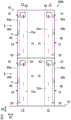
fig. 7 is a diagram showing another example of the repository according to the embodiment.
Detailed Description
Embodiments of the present invention will be described below with reference to the drawings. However, the present invention is not limited to this mode. In the drawings, a part of the description is enlarged or emphasized to show the embodiment, and the scale is appropriately changed. In each drawing, a horizontal direction (a direction parallel to the floor FL), that is, a longitudinal direction of a storage area 12 (or a traveling direction of a conveying mechanism 40 described later) is denoted as a 1 st direction D1, a horizontal direction, that is, a direction perpendicular to the 1 st direction D1 is denoted as a 2 nd direction D2, and an up-down direction perpendicular to the floor FL is denoted as a 3 rd direction D3.
Fig. 1 and 2 are diagrams showing an example of a repository 100 according to an embodiment. Fig. 1 is a sectional view of the cartridge 100 as viewed from above, and fig. 2 is a sectional view of the cartridge 100 as viewed from the side (direction D1 1). As shown in fig. 1 and 2, the storage warehouse 100 includes a main body portion 10, a rack portion 20, a transfer device 30, and a conveying mechanism 40. The storage 100 stores the article M therein. In the present embodiment, the article M is, for example, a reticle box that houses a reticle. The number of the reticles for accommodating the article M is 1 or more. When a plurality of reticles are stored, the articles M are stored in a vertically aligned state.
The main body 10 is installed on a floor FL of a building F such as a semiconductor factory, and manages, for example, the internal temperature and humidity. The main body 10 includes a wall 11, a storage area 12, a duct 13, a fan 14, a control panel storage 15, a 1 st heat insulating layer 16, and a 2 nd heat insulating layer 17. The wall 11 is disposed around a space including the storage area 12, and partitions the inside and outside of the storage box 100. The wall portion 11 is formed in a rectangular shape when viewed from above, for example. The storage area 12 is a space for storing the articles M, and is provided inside the wall 11. The storage area 12 is formed on both sides of the area where the transport mechanism 40 (transfer device 30) travels.
The ducts 13 are disposed on the wall 11 side of the 2 storage areas 12. The duct 13 is, for example, rectangular box-shaped and extends in the vertical direction. The duct 13 is provided in the vertical direction so as to extend from the lowermost portion to the uppermost portion of the storage area 12. The plurality of ducts 13 are arranged in parallel along the horizontal direction (the 1 st direction D1) of the wall portion 11. In fig. 1, the duct 13 is provided corresponding to 2 articles M placed on the shelf portion 20, but the present invention is not limited to this configuration, and the duct 13 may be provided corresponding to 1 article M, or the duct 13 may be provided corresponding to 3 or more articles M. The plurality of pipes 13 arranged in the horizontal direction may be the same size or different sizes.
The duct 13 is formed by disposing an inner duct wall 13e and an outer duct wall 13f at a predetermined interval, and has an inlet 13a, a flow regulating portion 13b, and ejection ports 13c and 13 d. In addition, the outer conduit wall 13f forms the wall 11 of the reservoir 100. The inlet 13a is disposed at the upper end of the duct 13. The inlet 13a introduces air flowing downward into the duct 13.
The inlet 13a introduces air blown downward by a ceiling fan CF provided in the ceiling portion CL of the building F. Further, a plurality of ceiling fans CF are disposed in the ceiling portion CL of the building F, and a down flow is formed in the building F. The ceiling fan CF may use, for example, a fan filter unit. The inlet 13a is disposed in a state of being opened upward so as to take a part of the down airflow (air flowing downward) generated by the ceiling fan CF into the duct 13.
The flow regulating portion 13b is disposed in the duct 13. The flow regulating portion 13b is, for example, a partition plate that partitions the upper side and the lower side of the duct 13. The flow restricting portion 13b restricts the flow of air between the upper side and the lower side of the duct 13. The flow regulating portion 13b regulates the flow of air introduced from the inlet 13a to the lower side of the duct 13. The flow regulating portion 13b is not limited to a structure in which the upper side and the lower side of the duct 13 are separated without a gap. The flow regulating portion 13b may be disposed with a gap from the wall of the duct 13, or may be a filter having a small air permeability.
The height of the flow regulating portion 13b can be set arbitrarily. The flow regulating portion 13b may be provided at a height at or near an intermediate position in the vertical direction of the duct 13, for example. Further, for example, when the down airflow generated by the ceiling fan CF is strong, the height of the flow restriction portion 13b can be set lower than the middle position in the vertical direction of the duct 13 because the air is sufficiently sent to the lower side of the duct 13; in the case where the down airflow generated by the ceiling fan CF is weak, the air cannot be sufficiently sent to the lower side of the duct 13, and therefore the height of the flow restriction portion 13b can be set to be higher than the middle position in the vertical direction of the duct 13. The height of the flow regulating portion 13b may be changed in the vertical direction. Whether or not the flow regulating portion 13b is provided is arbitrary, and the flow regulating portion 13b may not be provided.
The discharge ports 13c and 13d are provided in the duct wall 13e on the storage area 12 side of the duct 13. The ejection ports 13c and 13d are formed in a plurality of places to eject the air introduced into the duct 13 into the storage area 12. The ejection port 13c is formed in the duct wall portion 13e of the upper portion 13P of the flow regulating portion 13b in the duct 13. The ejection port 13d is formed on the duct wall portion 13e of the lower portion 13Q of the flow regulating portion 13b in the duct 13. The duct wall portion 13e is made of, for example, a perforated metal plate. Although not shown, the plurality of discharge ports 13c and 13d may be arranged at equal intervals in the lower portion 13Q and the upper portion 13P, for example, in the vertical direction and the horizontal direction, or may be arranged at unequal intervals if a desired function is satisfied. The aperture ratios of the lower portion 13Q and the upper portion 13P may be fixed in the vertical direction or may be changed in the vertical direction.
The fan 14 is disposed at the lower portion 13Q of the duct 13. The fan 14 may be disposed at the upper portion 13P of the duct 13. The fan 14 is disposed on a duct wall 13f of the duct 13 facing the storage area 12. The conduit wall 13f is arranged facing the outside of the reservoir 100. The fan 14 causes the air inlet to face the wall portion 11 of the reservoir 100, sucks air outside the wall portion 11 (body portion 10), and introduces the air into the lower portion 13Q of the duct 13. The air outside the main body portion 10 is air inside the building F and is a part of the down-flow generated by the ceiling fan CF. Also, the fan 14 is, for example, a fan filter unit.
The fan 14 horizontally ejects the sucked outside air toward the storage area 12 via the lower portion 13Q of the duct 13. That is, the air sucked into the lower portion 13Q of the duct 13 is ejected in the 2 nd direction D2 toward the storage area 12 from the plurality of ejection ports 13D by the fan 14.
As shown in fig. 1, the fans 14 may be arranged in a row without a gap in the horizontal direction of the lower portion 13Q of the duct 13, or may have a gap. As shown in fig. 2, the fans 14 may be arranged in the vertical direction of the lower portion 13Q of the duct 13 without a gap, or may have a gap. The same fan 14 may be used for the plurality of fans 14, but the present invention is not limited to this configuration, and for example, different fans 14 may be disposed in the vertical direction and the horizontal direction. The plurality of fans 14 are not limited to being driven all at once, and may be driven alternately or sequentially. Further, some or all of the plurality of fans 14 are not limited to continuous driving, and may be intermittently driven.
The control board storage unit 15 stores 1 or more control boards CR that control each part of the magazine 100. Fig. 3 is a side view of the magazine 100, showing the state of the control disk storage unit 15 viewed from the side (direction D1 1). Fig. 4 is a front view of the magazine 100, showing a state in which the control disk storage unit 15 is viewed from the front. Fig. 5 is a sectional view taken along line a-a of fig. 4. Fig. 6 is a sectional view taken along line B-B of fig. 3. As shown in fig. 3, the control board storage 15 is disposed at 2 positions inside the wall 11 in the 2 nd direction D2 with an interval therebetween. As shown in fig. 4, the control board storage 15 is disposed on one end side of the storage area 12 in the 1 st direction D1 (i.e., on a side surface of the storage area 12).
The 2 nd fan 63 is provided on the surface on the 1 st direction D1 side above the control board storage 15. The 2 nd fan 63 is disposed on the wall portion 15a facing the outside in the control panel housing portion 15. That is, the 2 nd fan 63 is disposed on the side surface of the control panel storage 15 opposite to the storage area 12. This wall 15a forms part of the wall 11 of the magazine 100. The 2 nd fan 63 sucks the air in the control panel storage 15 and discharges the air to the outside of the storage container 100. The 2 nd fan 63 is disposed above the height of the fan 14 (see fig. 2). In the figure, 1 second fan 63 is used for each control board storage unit 15, but the present invention is not limited to this configuration, and a plurality of second fans 63 may be used for each control board storage unit 15.
The 1 st heat insulating layer 16 is disposed on the wall portion 11 side of the control panel housing portion 15. That is, the 1 st heat insulating layer 16 is disposed between the control board storage portion 15 and the wall portion 11 in the 2 nd direction D2. As shown in fig. 3 to 5, the 1 st insulating layer 16 has a duct 60 as a ventilation layer through which air can flow. The duct 60 extends in the vertical direction along the control panel housing portion 15 and includes a 1 st vent 61 and a 2 nd vent 62.
The 1 st vent 61 is disposed above the duct 60. The 1 st vent 61 is provided in the wall portion 60a on the wall portion 11 side in the duct 60. Wall portion 60a forms part of wall portion 11 of reservoir 100. The 1 st vent 61 is formed to open in the 2 nd direction D2. The 1 st vent 61 communicates the outside of the wall 11 with the inside of the duct 60. The opening of the 1 st vent 61 is formed in a rectangular shape, but the shape is not limited to this configuration, and may be formed in other shapes such as a circle, an ellipse, an oval, or a polygon. Further, a filter may be installed in the 1 st vent 61 in order to prevent the garbage from entering the duct 60.
The 2 nd vent 62 is disposed at a lower portion of the duct 60. The 2 nd vent 62 is provided in the wall portion 60b on the control panel accommodating portion 15 side of the duct 60. The upper end of the wall 60b is in contact with the lid 11b of the reservoir 100 and is closed, and the inside of the duct 60 and the inside of the console housing 15 are communicated with each other through the 2 nd vent 62. In the duct 60, the interval in the 2 nd direction D2 between the wall portion 60a and the wall portion 60b is set to an interval that can block or suppress heat transfer from the wall portion 60b to the wall portion 60a in the 2 nd direction D2 when air flows through the duct 60. For example, the interval between the wall 60a and the wall 60b in the 2 nd direction D2 may be set according to the flow rate of air flowing through the duct 60 by the 2 nd fan 63. The opening shape of the 2 nd vent 62 is formed in a rectangular shape, but is not limited to this configuration, and may be formed in other shapes such as a circle, an ellipse, an oval, or a polygon. The opening areas of the 1 st vent 61 and the 2 nd vent 62 may be the same or different.
As shown in fig. 3 and 5, the 2 nd fan 63 is driven to discharge the air in the control board storage 15 to the outside of the storage magazine 100, and the pressure in the control board storage 15 is reduced, so that the air in the duct 60 is introduced into the control board storage 15 through the 2 nd air vent 62. As air is introduced into the control panel housing portion 15, the pressure in the duct 60 decreases, and outside air is introduced into the duct 60 through the 1 st vent 61.
Therefore, when the 2 nd fan 63 is driven, an air flow is formed from the 1 st vent 61 through to the 2 nd fan 63. That is, the air outside the reservoir 100 is introduced into the duct 60 through the 1 st air vent 61 and flows downward in the duct 60. This air is introduced into the control panel storage 15 through the 2 nd air vent 62, flows upward in the control panel storage 15, and is discharged to the outside of the reservoir through the 2 nd fan 63.
The air flow carries away the heat generated in the control panel CR (see fig. 1) with the air flowing in the control panel housing 15, and the heat is discharged from the 2 nd fan 63 to the outside of the reservoir 100. In this way, the heat generated at the control disc CR is discharged to the outside of the reservoir 100 together with the air. The air also flows downward in the duct 60, and the heat of the control disk CR is prevented or suppressed from being transmitted from the wall portion 60b on the inner side of the duct 60 to the wall portion 60a and the wall portion 11 on the outer side in the 2 nd direction D2. In the configuration in which the fan 14 disposed in the wall portion 11 sucks outside air and introduces the air into the storage area 12, there is a possibility that air having a temperature increased by heat transferred to the outside from the wall portion 11 of the control panel housing portion 15 or the like is sucked by the fan 14 provided in the same wall portion 11. In the present embodiment, by providing the 1 st heat insulating layer 16, it is possible to block or suppress heat transfer from the control panel storage 15 to the wall portion 11 and the wall portion 60a, and it is possible to suppress a temperature increase of the air guided to the storage area 12 by the fan 14. Therefore, the fan 14 can be disposed on the wall portion 11 in the vicinity of the duct 60 (i.e., in the vicinity of the console box storage portion 15). Further, since the 2 nd fan 63 is mounted on a surface different from the surface on which the fan 14 (see fig. 1 and 2) is provided and above the fan 14, the air discharged from the 2 nd fan 63 is prevented from being introduced into the interior (storage area 12) of the storage box 100 from the fan 14.
The 2 nd heat insulating layer 17 is disposed on the storage area 12 side of the control panel storage unit 15. That is, the 2 nd heat insulating layer 17 is disposed between the control board storage 15 and the storage area 12 in the 1 st direction D1. As shown in fig. 4 and 6, the 2 nd insulating layer 17 has a duct 70 as a ventilation layer through which air can flow. The duct 70 extends vertically along the control panel housing 15 and has an inlet 71 and an outlet 72.
The inlet 71 is formed to open a part of the cover 11b at the upper end of the duct 70. The inlet 71 is opened toward the ceiling CL, for example, and introduces air in the building F into the duct 70. As described above, air flowing downward from the ceiling fan CF is formed in the ceiling portion CL of the building F, and the air from the ceiling fan CF is taken into the duct 70 through the inlet 71. However, the position of the introduction port 71 is not limited to the upper end of the duct 70. For example, the introduction port 71 may be provided at an upper portion of the wall portion 70a on the storage area 12 side of the duct 70. In this case, the air in the storage area 12 may be introduced into the duct 70 by a fan.
The discharge port 72 is disposed at the lower end of the duct 70. The discharge port 72 is formed to open downward, and is capable of discharging the air in the duct 70 downward of the reservoir 100. The duct 70 is provided to move the air introduced from the inlet 71 downward and discharge the air directly from below the reservoir 100. In addition, the discharge port 72 is not limited to the lower opening facing the duct 70. The discharge port 72 may be provided, for example, below the wall portion 70a on the storage area 12 side of the duct 70 or below the wall portion 70b on the control panel storage portion 15 side. When the discharge port 72 is provided at the lower portion of the wall portion 70b, the air in the duct 70 is sucked by the 2 nd fan 63.
The air outside the storage chamber 100 is introduced into the duct 70 from the inlet 71, flows downward in the duct 70, and is discharged outside the storage chamber 100 from the outlet 72. The air flow prevents or suppresses the heat generated in the control panel CR (see fig. 1) from being transferred in the 1 st direction D1 to reach the storage area 12. In the duct 70, the interval in the 1 st direction D1 between the wall portion 70a and the wall portion 70b is set to an interval that can block or suppress heat transfer from the wall portion 70b to the wall portion 70a in the 1 st direction D1 when air flows through the duct 70. For example, the interval in the 1 st direction D1 between the wall portion 70a and the wall portion 70b may be set according to the flow rate of the air introduced from the ceiling fan CF via the introduction port 71.
As shown in fig. 2, the main body portion 10 includes a connecting portion 11a and a lid portion 11 b. The connection portion 11a is provided to extend from the upper portion of the wall portion 11 to the ceiling portion CL. The connecting portion 11a is disposed around the wall portion 11 of the magazine 100 when viewed from above. With this configuration, the connection portion 11a guides the air flowing downward by the ceiling fan CF of the ceiling portion CL to the upper side of the storage container 100 (the upper side of the space surrounded by the wall portion 11). The air blown downward by the ceiling fan CF of the ceiling portion CL can be easily taken into the inlet 71 of the duct 70 by the connection portion 11 a.
The lid 11b closes the upper end of the internal space of the storage container 100 including the storage area 12. The cover 11b can restrict the air blown downward by the ceiling fan CF of the ceiling CL from directly entering the interior of the storage container 100. Air is supplied from the duct 13 to the storage area 12 through the ejection ports 13c and 13 d. Further, the provision of the cover 11b prevents air from leaking from the inside of the storage container 100 to the upper side.
Whether the connecting portion 11a and the cover portion 11b are provided or not may be arbitrary, and one or both of the connecting portion 11a and the cover portion 11b may be omitted. The coupling portion 11a and the lid portion 11b are not limited to being provided without a gap, and may be provided with a gap provided between some portions. The connecting portion 11a is not limited to extending upward from the wall portion 11 of the storage container 100, and may be provided so as to extend outward or retract inward from the wall portion 11, for example.
The shelf unit 20 is disposed in the storage area 12 and is formed to be able to place the article M thereon. The rack unit 20 is supported by a column unit or the like, not shown, and is provided in multiple stages in the vertical direction in the storage area 12. In the present embodiment, the multi-deck rack units 20 are disposed on both sides along the traveling direction of the conveying mechanism 40. Each shelf portion 20 is formed with a notch portion, not shown. Each shelf unit 20 may be provided with 3 pins, not shown, on the upper surface. The pin is provided to protrude upward from the upper surface of the shelf portion 20, and can enter the groove portion provided on the bottom surface of the article M to position the article M on the shelf portion 20.
Each shelf unit 20 is provided with a supply nozzle 21 of a cleaning device. The supply nozzle 21 is disposed so as to be connected to a cleaning gas inlet, not shown, provided in the bottom surface of the article M when the article M is placed on the rack unit 20. When the article M is placed on the shelf portion 20, the purge gas inlet of the article M is connected to a purge gas source 23 from the supply nozzle 21 via the pipe 22, and the purge gas is supplied into the article M via the purge gas inlet. The supply nozzle 21 may not be provided in a part or the whole of the shelf unit 20. The supply of the cleaning gas to the articles M may be performed outside the rack unit 20, or the cleaning gas may be supplied to the articles M at, for example, a loading port, not shown, for loading the articles M into the stocker 100.
The transfer device 30 transfers the article M to the rack unit 20 as a transfer location. The transfer device 30 includes a base 31, an expansion/contraction portion 32, and an article holding portion 33. The base 31 is fixed to an elevating table 43 described later. The expansion portion 32 is provided to be expandable and contractible with respect to the base portion 31. The article holding portion 33 is attached to the tip of the expansion portion 32, and can hold the article M. The article holding portion 33 is movable in a direction in which the stretchable portion 32 stretches, for example. The article holding portion 33 is configured to carry and hold the article M, and is capable of passing through the notch of the rack portion 20 in the vertical direction. The transfer device 30 is not limited to a configuration for placing the article M, and may be, for example, a configuration for holding the article M with a flange portion provided at an upper portion thereof interposed therebetween, or a configuration for holding the article M by gripping a side surface thereof.
The conveyance mechanism 40 includes a rail R, a travel unit, not shown, that travels along the rail R, a column 42 provided on the travel unit, and an elevating platform 43 that ascends and descends along the column 42. The rails R are disposed in parallel on the floor and ceiling (cover 11b) in the storage 100. The rail R is arranged parallel to the wall 11 on which the fan 14 is provided, along the 1 st direction D1 (along the storage area 12). Although fig. 1 shows 2 tracks R, the number of tracks R is arbitrary, and 1 track R may be used. The traveling unit traveling on the track R travels along the track R under the drive of a drive unit such as a motor. The column 42 is disposed along the vertical direction and moves together with the traveling unit by driving the traveling unit. The elevating table 43 is driven by a driving source such as a motor to be vertically elevated along the column 42, and is held at an arbitrary height.
In the storage 100, the movement of the article M into and out of the storage 100, the movement of transferring the article M to the shelf unit 20, and the like are controlled by a control panel CR (control unit) housed in the control panel housing unit 15. When an article M is loaded into the storage warehouse 100, the transfer device 30 receives the article M placed on a loading port, not shown, and then the transfer device 30 is moved to the rack unit 20 at the loading destination by the conveying mechanism 40. Then, the extensible part 32 of the transfer device 30 is extended from the base part 31, the article holding part 33 is moved above the rack part 20, and the elevating platform 43 is lowered in this state, whereby the article M is transferred to the rack part 20. By this operation, the article M is placed on the rack unit 20 at the conveyance destination.
When the article M is carried out, the transfer device 30 is moved by the conveying mechanism 40 to the shelf portion 20 on which the article M to be carried out is placed. Next, the extendable unit 32 is extended to move the article holding unit 33 below the shelf unit 20, and the elevating platform 43 is raised in this state, whereby the article M is transferred from the shelf unit 20 to the article holding unit 33. Then, the stretchable and contractible portion 32 is contracted to hold the article holding portion 33 on which the article M is placed on the base portion 31. Then, the transfer device 30 is moved to the loading port by the conveying mechanism 40, and the article M is placed on the loading port by the transfer device 30. This operation completes the carrying-out of the article M.
When the control unit performs the above operation of the repository 100, the control panel CR generates heat. In the storage box 100 of the present embodiment, the heat generated in the control disk CR is discharged to the outside of the storage box 100 by the 1 st heat insulating layer 16 and the 2 nd heat insulating layer 17, and the heat of the control disk CR is prevented from being transmitted to the storage area 12, so that the temperature of the air taken in by the fan 14 does not increase.
Specifically, in the 1 st heat insulating layer 16, the 2 nd fan 63 is driven to introduce air from the outside of the storage tank 100 into the duct 60 through the 1 st air vent 61, and the air flows through the control board housing portion 15 through the 2 nd air vent 62, takes away heat from the control board CR, and is discharged from the 2 nd fan 63 to the outside of the storage tank 100, thereby suppressing the temperature rise of the air taken in by the fan 14. In the 2 nd insulating layer 17, the air flowing downward from the ceiling fan CF of the ceiling portion CL flows downward in the duct 70 through the inlet 71 and is discharged downward of the storage compartment 100 through the outlet 72, and the heat transfer of the control disk CR to the storage area 12 is suppressed. Therefore, in the storage area 12 of the stocker 100, a temperature increase due to heat of the control disk CR is suppressed. Both the 1 st insulation layer 16 and the 2 nd insulation layer 17 discharge the intake air to the outside without circulating the air in the reservoir 100. By discharging this air, the temperature in the storage container 100 (storage area 12) is prevented from rising.
As described above, since the repository 100 according to the present embodiment includes the 1 st heat-insulating layer 16 disposed on the wall portion 11 side of the control board storage portion 15 and the 2 nd heat-insulating layer 17 disposed on the storage area 12 side of the control board storage portion 15, heat transfer from the control board CR to the storage area 12 is blocked or suppressed on the wall portion 11 side and the storage area 12 side of the control board storage portion 15, and a temperature increase of air taken in by the fan 14 is blocked or suppressed. With this configuration, the influence of heat on the articles M placed in the storage area 12 can be reduced.
FIG. 7 is a diagram showing another example of a repository. The magazine 100A shown in fig. 7 is provided with 2-level control disk storage units 15 on the upper and lower sides. The storage magazine 100A shown in fig. 7 has the same configuration as the storage magazine 100 shown in fig. 1 except that the 2-tier control disk storage unit 15 is provided at the upper and lower sides. The 1 st heat insulating layer 16 is formed for each layer, and the 2 nd fan 63 is disposed in the control panel storage 15 for each layer. The 2 nd insulating layer 17 may be formed by connecting an upper duct 70 and a lower duct 70, for example.
According to the magazine 100A, heat transfer from the control disks CR disposed in the control disk storage 15 disposed for each floor to the storage area 12 can be efficiently blocked or suppressed. Fig. 7 shows an example in which the control board storage unit 15 has 2 layers, but the same applies to the case in which the control board storage unit 15 has 3 or more layers.
The embodiments have been described above, but the present invention is not limited to the above description, and various modifications can be made without departing from the spirit of the present invention. For example, in the above embodiment, the description has been given by taking as an example a configuration in which the heat insulating layer 2 has the duct 70 as a ventilation layer that allows air to flow, but the configuration is not limited to this configuration. For example, insulation material may be used in place of the pipe 70 for the 2 nd insulation layer 17. As the heat insulating material, for example, a resin material such as styrofoam, wood, paper, or the like can be used. Also, the 2 nd insulation 17 may also use a pipe 60 similar to that used in the 1 st insulation 16 in place of the pipe 70. In this case, the 2 nd heat insulating layer 17 may be configured to receive air from the outside or the reservoir 100 by operating the 2 nd fan 63 and to discharge the air to the outside through the control panel storage unit 15.
Further, although the duct 60 is used as the 1 st heat insulating layer 16 in the above embodiment, a heat insulating material such as foamed polystyrene may be used instead of this structure, similarly to the 2 nd heat insulating layer 17. In this case, for example, a structure may be employed in which a vent is provided at the lower portion of the control board storage portion 15, and when the 2 nd fan 63 is operated, air is introduced from the outside of the storage compartment 100 into the control board storage portion 15 through the vent, flows upward in the control board storage portion 15, and is then discharged from the 2 nd fan 63 to the outside of the storage compartment. Also, the 1 st insulation 16 may also use a tube 70 similar to that used in the 2 nd insulation 17 in place of the tube 60. In this case, the 1 st insulating layer 16 may be configured to receive air flowing downward from the ceiling fan CF of the ceiling portion CL from the inlet 71 and to discharge the air downward from the outlet 72 to the lower side of the storage 100.
In the above description, the 2 nd fan 63 is disposed above the fan 14 as an example, but the present invention is not limited to this configuration. For example, the 2 nd fan 63 may be disposed at the same height as the fan 14. The 2 nd fan 63 may be disposed below the fan 14. When the 2 nd fan 63 is disposed below the control panel housing portion 15, the 2 nd air vent 62 is disposed above the duct 60, and the 1 st air vent 61 is disposed below the duct 60. With this arrangement, when the 2 nd fan 63 is driven, the air introduced from the 1 st vent 61 flows upward in the duct 60, and the air introduced from the 2 nd vent 62 into the control board storage 15 flows downward in the control board storage 15, and is discharged from the 2 nd fan 63 to the outside of the storage warehouse 100. Further, the contents of all documents cited in japanese patent application No. 2017-020225, the above-mentioned embodiments and the like are cited as a part of the present specification within the allowable range by law and regulation.
Description of reference numerals
M-an article; CR-control panel; 11-a wall portion; 15a, 60b, 70 a-wall section; 12-a storage area; 13. 60, 70-pipeline; 13c, 13 d-ejection port; 14-a fan; 15-a control panel housing section; 16-1 st insulating layer; 17-2 nd thermal insulation layer; 20-a shelf portion; 61-vent 1; vent 62-No. 2; 63-2 nd fan; 100. 100A — repository.
Claims (7)
1. A repository is provided with:
a wall portion for dividing the interior and exterior of the reservoir,
a storage area disposed inside the wall portion and storing articles,
a fan disposed on the wall portion for sucking external air and guiding the air into the interior,
a control panel storage part arranged on the side surface of the storage area inside the wall part and used for storing a control panel,
a first heat insulating layer 1 disposed on the side of the wall portion of the control panel accommodating portion, and
a 2 nd heat insulating layer disposed on the storage area side of the control panel storage unit;
the wall portion is formed in a rectangular shape when viewed from above;
the fan is arranged on the wall part along the 1 st direction;
the control panel storage section is disposed on one end side in the 1 st direction with respect to the storage area;
the 1 st heat insulating layer is disposed between the control panel storage portion and the wall portion on which the fan is disposed, in a 2 nd direction orthogonal to the 1 st direction;
the 2 nd heat insulating layer is disposed between the control panel storage section and the storage area.
2. The storage of claim 1 wherein the 1 st insulating layer is a ventilation layer that allows air to circulate.
3. The reservoir of claim 2, the ventilation layer is a tube extending in an up-down direction;
the pipe has:
a 1 st vent hole disposed in one of the upper portion and the lower portion and communicating an outside of the wall portion with an inside of the duct,
a second air vent 2 disposed in the other of the upper part and the lower part and communicating the interior of the duct with the interior of the control panel housing part, and
and a 2 nd fan disposed on a side surface of the control board storage portion opposite to the storage area, for sucking air inside the control board storage portion and discharging the air to the outside of the storage room.
4. The storage of claim 3 wherein said 2 nd fan is disposed above said fan.
5. The storage warehouse of claim 3, wherein the control board storage part is provided with a plurality of layers on the upper and lower sides;
the 2 nd fan is disposed for each floor.
6. The storage warehouse of claim 4, wherein the control board storage part is provided with a plurality of layers on the upper and lower sides;
the 2 nd fan is disposed for each floor.
7. The reservoir of any of claims 1 to 6, the 2 nd insulation layer is a ventilation layer enabling air circulation.
Applications Claiming Priority (3)
| Application Number | Priority Date | Filing Date | Title |
|---|---|---|---|
| JP2017020225 | 2017-02-07 | ||
| JP2017-020225 | 2017-02-07 | ||
| PCT/JP2018/000435 WO2018146986A1 (en) | 2017-02-07 | 2018-01-11 | Stocker |
Publications (2)
| Publication Number | Publication Date |
|---|---|
| CN110225868A CN110225868A (en) | 2019-09-10 |
| CN110225868B true CN110225868B (en) | 2021-02-26 |
Family
ID=63107380
Family Applications (1)
| Application Number | Title | Priority Date | Filing Date |
|---|---|---|---|
| CN201880008789.1A Active CN110225868B (en) | 2017-02-07 | 2018-01-11 | repository |
Country Status (9)
| Country | Link |
|---|---|
| US (1) | US11222803B2 (en) |
| EP (1) | EP3581521B1 (en) |
| JP (1) | JP6760406B2 (en) |
| KR (1) | KR102227859B1 (en) |
| CN (1) | CN110225868B (en) |
| IL (1) | IL268311A (en) |
| SG (1) | SG11201906971VA (en) |
| TW (1) | TWI729266B (en) |
| WO (1) | WO2018146986A1 (en) |
Family Cites Families (15)
| Publication number | Priority date | Publication date | Assignee | Title |
|---|---|---|---|---|
| JPS5059974A (en) * | 1973-10-02 | 1975-05-23 | ||
| JPH03122004U (en) * | 1990-03-28 | 1991-12-12 | ||
| JP2007027780A (en) * | 1999-10-19 | 2007-02-01 | Tokyo Electron Ltd | Substrate processing equipment |
| JP2003192106A (en) * | 2001-12-28 | 2003-07-09 | Itoki Crebio Corp | Automated warehouse and transfer and place device used for it |
| KR101269384B1 (en) * | 2004-12-28 | 2013-05-29 | 엘지디스플레이 주식회사 | Stocker apparatus |
| JP2009140421A (en) * | 2007-12-10 | 2009-06-25 | Toyo Netsu Kogyo Kk | Server rack and data center provided with the same |
| JP4437561B2 (en) * | 2008-04-01 | 2010-03-24 | 村田機械株式会社 | Airflow measurement unit |
| JP4706938B2 (en) * | 2008-11-21 | 2011-06-22 | 村田機械株式会社 | Clean room automatic warehouse and how to store goods in automatic warehouse |
| JP4884486B2 (en) * | 2009-02-03 | 2012-02-29 | 東京エレクトロン株式会社 | Substrate buffer unit |
| CN201781195U (en) * | 2010-06-30 | 2011-03-30 | 比亚迪股份有限公司 | Outdoor power supply cabinet |
| JP5874691B2 (en) * | 2013-06-26 | 2016-03-02 | 株式会社ダイフク | Inert gas supply equipment |
| CN203491553U (en) * | 2013-09-04 | 2014-03-19 | 常熟开关制造有限公司(原常熟开关厂) | Photovoltaic direct-current power-distribution cabinet |
| JP6279379B2 (en) * | 2014-03-28 | 2018-02-14 | 三機工業株式会社 | Three-dimensional warehouse air conditioning system |
| JP2016021429A (en) * | 2014-07-11 | 2016-02-04 | 村田機械株式会社 | Purge stocker |
| JP6608200B2 (en) | 2015-07-09 | 2019-11-20 | 大和ハウス工業株式会社 | Drainer |
-
2018
- 2018-01-11 US US16/483,460 patent/US11222803B2/en active Active
- 2018-01-11 WO PCT/JP2018/000435 patent/WO2018146986A1/en not_active Ceased
- 2018-01-11 KR KR1020197022459A patent/KR102227859B1/en active Active
- 2018-01-11 EP EP18751500.2A patent/EP3581521B1/en active Active
- 2018-01-11 CN CN201880008789.1A patent/CN110225868B/en active Active
- 2018-01-11 JP JP2018566801A patent/JP6760406B2/en active Active
- 2018-01-11 SG SG11201906971VA patent/SG11201906971VA/en unknown
- 2018-02-06 TW TW107104072A patent/TWI729266B/en active
-
2019
- 2019-07-28 IL IL268311A patent/IL268311A/en active IP Right Grant
Also Published As
| Publication number | Publication date |
|---|---|
| KR20190102049A (en) | 2019-09-02 |
| WO2018146986A1 (en) | 2018-08-16 |
| KR102227859B1 (en) | 2021-03-15 |
| TW201830557A (en) | 2018-08-16 |
| IL268311A (en) | 2019-09-26 |
| TWI729266B (en) | 2021-06-01 |
| US11222803B2 (en) | 2022-01-11 |
| EP3581521A4 (en) | 2020-11-18 |
| EP3581521B1 (en) | 2021-08-11 |
| CN110225868A (en) | 2019-09-10 |
| JPWO2018146986A1 (en) | 2019-12-12 |
| US20200035534A1 (en) | 2020-01-30 |
| JP6760406B2 (en) | 2020-09-23 |
| EP3581521A1 (en) | 2019-12-18 |
| SG11201906971VA (en) | 2019-08-27 |
Similar Documents
| Publication | Publication Date | Title |
|---|---|---|
| US10274214B2 (en) | Storage facility | |
| KR100524359B1 (en) | Storage facility for use in a clean-room | |
| US20160296984A1 (en) | Purge device and method of diffusing gas including purge gas | |
| CN110249419B (en) | Storage repository | |
| CN107808844B (en) | container containment equipment | |
| JP2016021429A (en) | Purge stocker | |
| CN110225868B (en) | repository | |
| CN101276772B (en) | Stocker for semiconductor substrate | |
| KR20060122682A (en) | Automatic warehouse | |
| US20180076079A1 (en) | Article Storage Facility | |
| JP2003081405A (en) | Purified air circulation type storage equipment | |
| JP4780396B2 (en) | Goods storage facilities and goods storage facilities for clean rooms | |
| KR20170113389A (en) | Container storage facility | |
| JP2007269489A (en) | Goods storage equipment for clean rooms | |
| JPH03152004A (en) | Cargo storing device in clean room |
Legal Events
| Date | Code | Title | Description |
|---|---|---|---|
| PB01 | Publication | ||
| PB01 | Publication | ||
| SE01 | Entry into force of request for substantive examination | ||
| SE01 | Entry into force of request for substantive examination | ||
| GR01 | Patent grant | ||
| GR01 | Patent grant |