CN110185427B - Method for acquiring natural crack opening time under condition of temporary plugging in crack - Google Patents
Method for acquiring natural crack opening time under condition of temporary plugging in crack Download PDFInfo
- Publication number
- CN110185427B CN110185427B CN201910387470.0A CN201910387470A CN110185427B CN 110185427 B CN110185427 B CN 110185427B CN 201910387470 A CN201910387470 A CN 201910387470A CN 110185427 B CN110185427 B CN 110185427B
- Authority
- CN
- China
- Prior art keywords
- fracture
- hydraulic
- hydraulic fracture
- unit
- natural
- Prior art date
- Legal status (The legal status is an assumption and is not a legal conclusion. Google has not performed a legal analysis and makes no representation as to the accuracy of the status listed.)
- Active
Links
- 238000000034 method Methods 0.000 title claims abstract description 38
- 239000012530 fluid Substances 0.000 claims abstract description 53
- 238000004364 calculation method Methods 0.000 claims abstract description 23
- 230000008569 process Effects 0.000 claims abstract description 19
- 230000015572 biosynthetic process Effects 0.000 claims description 42
- 239000011435 rock Substances 0.000 claims description 22
- 238000005086 pumping Methods 0.000 claims description 5
- 238000006073 displacement reaction Methods 0.000 claims description 4
- 230000000704 physical effect Effects 0.000 claims description 3
- XLYOFNOQVPJJNP-UHFFFAOYSA-N water Substances O XLYOFNOQVPJJNP-UHFFFAOYSA-N 0.000 claims 1
- 238000013461 design Methods 0.000 abstract description 4
- 239000003795 chemical substances by application Substances 0.000 description 4
- 238000012986 modification Methods 0.000 description 3
- 230000004048 modification Effects 0.000 description 3
- 230000000694 effects Effects 0.000 description 2
- 238000005516 engineering process Methods 0.000 description 2
- 239000000463 material Substances 0.000 description 2
- VNWKTOKETHGBQD-UHFFFAOYSA-N methane Chemical compound C VNWKTOKETHGBQD-UHFFFAOYSA-N 0.000 description 2
- 239000004576 sand Substances 0.000 description 2
- 230000000638 stimulation Effects 0.000 description 2
- 238000010521 absorption reaction Methods 0.000 description 1
- 230000009471 action Effects 0.000 description 1
- 238000004458 analytical method Methods 0.000 description 1
- 230000006835 compression Effects 0.000 description 1
- 238000007906 compression Methods 0.000 description 1
- 230000007812 deficiency Effects 0.000 description 1
- 238000011161 development Methods 0.000 description 1
- 239000007789 gas Substances 0.000 description 1
- 239000003345 natural gas Substances 0.000 description 1
- 238000011160 research Methods 0.000 description 1
- 238000007789 sealing Methods 0.000 description 1
- 230000009466 transformation Effects 0.000 description 1
Images

Classifications
-
- E—FIXED CONSTRUCTIONS
- E21—EARTH OR ROCK DRILLING; MINING
- E21B—EARTH OR ROCK DRILLING; OBTAINING OIL, GAS, WATER, SOLUBLE OR MELTABLE MATERIALS OR A SLURRY OF MINERALS FROM WELLS
- E21B49/00—Testing the nature of borehole walls; Formation testing; Methods or apparatus for obtaining samples of soil or well fluids, specially adapted to earth drilling or wells
-
- E—FIXED CONSTRUCTIONS
- E21—EARTH OR ROCK DRILLING; MINING
- E21B—EARTH OR ROCK DRILLING; OBTAINING OIL, GAS, WATER, SOLUBLE OR MELTABLE MATERIALS OR A SLURRY OF MINERALS FROM WELLS
- E21B43/00—Methods or apparatus for obtaining oil, gas, water, soluble or meltable materials or a slurry of minerals from wells
- E21B43/25—Methods for stimulating production
- E21B43/26—Methods for stimulating production by forming crevices or fractures
-
- E—FIXED CONSTRUCTIONS
- E21—EARTH OR ROCK DRILLING; MINING
- E21B—EARTH OR ROCK DRILLING; OBTAINING OIL, GAS, WATER, SOLUBLE OR MELTABLE MATERIALS OR A SLURRY OF MINERALS FROM WELLS
- E21B33/00—Sealing or packing boreholes or wells
- E21B33/10—Sealing or packing boreholes or wells in the borehole
- E21B33/13—Methods or devices for cementing, for plugging holes, crevices or the like
- E21B33/138—Plastering the borehole wall; Injecting into the formation
Landscapes
- Life Sciences & Earth Sciences (AREA)
- Engineering & Computer Science (AREA)
- Geology (AREA)
- Mining & Mineral Resources (AREA)
- Physics & Mathematics (AREA)
- Environmental & Geological Engineering (AREA)
- Fluid Mechanics (AREA)
- General Life Sciences & Earth Sciences (AREA)
- Geochemistry & Mineralogy (AREA)
- Investigating Strength Of Materials By Application Of Mechanical Stress (AREA)
Abstract
本发明公开一种缝内暂堵条件下天然裂缝开启时机的获取方法,包括以下步骤:根据现场地质资料得到地层物性参数;再将水力裂缝划分为长度相等的N个单元体并依次编号,即每个单元体的长度为L/N;同时以缝内暂堵时刻作为初始时刻t0,将总计算时间t划分为间隔相同的m个时间节点,相邻时间节点的间隔时间为t/m;计算初始时刻水力裂缝内各个单元体的宽度;计算第k个时间节点水力裂缝内流体压力;再计算第k个时间节点水力裂缝上、下两侧天然裂缝入口处所受闭合应力;判断准则进行判断天然裂缝是否开启。本发明原理可靠,计算精度高,能够精确计算出缝内暂堵转向压裂过程中天然裂缝的开启时机,进而为压裂方案设计提供有效指导。

The invention discloses a method for obtaining the opening timing of natural fractures under the condition of temporary plugging in fractures. The length of each unit body is L/N; at the same time, the moment of temporary blockage in the fracture is taken as the initial time t 0 , and the total calculation time t is divided into m time nodes with the same interval, and the interval time between adjacent time nodes is t/m ; Calculate the width of each unit body in the hydraulic fracture at the initial time; calculate the fluid pressure in the hydraulic fracture at the k-th time node; then calculate the closing stress at the entrance of the natural fractures on the upper and lower sides of the hydraulic fracture at the k-th time node; Judgment criteria To determine whether natural cracks are open. The invention has reliable principle and high calculation accuracy, and can accurately calculate the opening timing of natural fractures in the process of temporary plugging and diverting fracturing in fractures, thereby providing effective guidance for fracturing plan design.
Description
技术领域technical field
本发明涉及一种缝内暂堵条件下天然裂缝开启时机的获取方法,属于石油天然气勘探开发领域。The invention relates to a method for obtaining the opening timing of natural fractures under the condition of temporary plugging in fractures, and belongs to the field of oil and natural gas exploration and development.
背景技术Background technique
水力压裂技术是低渗透油气藏增产改造的重要措施。水力压裂是利用地面高压泵组,以超过地层吸收能力的排量将压裂液泵入地层来产生水力裂缝,然后继续注入带有支撑剂(砂粒)的压裂液,使裂缝继续延伸并在其中充填支撑剂,当压裂液返排后,在地层压力作用下,支撑剂在裂缝中起到支撑裂缝的作用,阻止裂缝闭合,从而在地层中形成具有一定长度和流动能力的填砂裂缝。Hydraulic fracturing technology is an important measure for stimulation and stimulation of low-permeability oil and gas reservoirs. Hydraulic fracturing is the use of ground high-pressure pump sets to pump fracturing fluid into the formation with a displacement exceeding the absorption capacity of the formation to generate hydraulic fractures, and then continue to inject fracturing fluid with proppant (sand) to continue to extend the fractures. The proppant is filled in it. When the fracturing fluid is flowed back, under the action of formation pressure, the proppant plays the role of propping the fracture in the fracture and prevents the fracture from closing, thereby forming sand filling with a certain length and flow capacity in the formation. crack.
缝内暂堵转向压裂是水力压裂的一种形式,具体是指在压裂过程中泵入暂堵剂对水力裂缝尖端进行暂时封堵,人为限制水力裂缝尖端向前延伸,迫使水力裂缝内部流体压力大幅上升,进而开启水力裂缝周围的天然裂缝,达到增加压裂改造范围的目的。因此,准确获取缝内暂堵条件下天然裂缝开启时机对于天然裂缝延伸过程预测和暂堵转向压裂工艺设计具有十分重要的意义。In-fracture temporary plugging and diverting fracturing is a form of hydraulic fracturing. Specifically, during the fracturing process, a temporary plugging agent is pumped to temporarily plug the hydraulic fracture tip, artificially restricting the forward extension of the hydraulic fracture tip and forcing the hydraulic fracture. The internal fluid pressure rises sharply, which in turn opens the natural fractures around the hydraulic fractures to increase the scope of fracturing. Therefore, it is of great significance to accurately obtain the opening timing of natural fractures under the condition of temporary plugging in fractures for the prediction of natural fracture propagation process and the design of temporary plugging and diverting fracturing technology.
暂堵失效是指压裂过程中水力裂缝内部压裂液突破尖端暂堵区域,导致暂堵段失去封堵作用,水力裂缝继续沿原路径向前延伸的现象;一般暂堵失效发生的条件为暂堵段两侧压力之差达到临界值,该临界值也被称为暂堵强度,由暂堵剂本身性质所决定。Temporary plugging failure refers to the phenomenon that the fracturing fluid inside the hydraulic fracture breaks through the temporary plugging area at the tip during the fracturing process, causing the temporary plugging section to lose its sealing effect and the hydraulic fracture to continue to extend forward along the original path. Generally, the conditions for temporary plugging failure are as follows: The pressure difference between the two sides of the temporary plugging section reaches a critical value, which is also called the temporary plugging strength, which is determined by the properties of the temporary plugging agent itself.
天然裂缝是相对于人工裂缝而言的,指的是地层中由于地壳运动或其它自然因素而天然存在的一类裂缝。在水力压裂过程中,当水力裂缝向前延伸时通常会与天然裂缝相遇,此时存在两种可能情况:水力裂缝直接穿过天然裂缝沿原路径向前延伸,或水力裂缝沿天然裂缝所在路径向前延伸;缝内暂堵转向压裂主要适用于第一种情况,即当水力裂缝穿过天然裂缝后天然裂缝仍然保持闭合,随后通过泵入暂堵剂提升水力裂缝内部流体压力,进而迫使天然裂缝开启。另外,根据水力裂缝与天然裂缝相交时的相对位置,可将相交过程划分为两种类型:正交(垂直相交)和非正交。Natural fractures are relative to artificial fractures, which refer to a type of fractures that naturally exist in the formation due to crustal movement or other natural factors. In the process of hydraulic fracturing, when the hydraulic fractures extend forward, they usually meet with natural fractures. At this time, there are two possible situations: the hydraulic fractures directly pass through the natural fractures and extend forward along the original path, or the hydraulic fractures follow the natural fractures. The path extends forward; the temporary plugging in the fractures is mainly suitable for the first case, that is, when the hydraulic fractures pass through the natural fractures, the natural fractures remain closed, and then the fluid pressure inside the hydraulic fractures is increased by pumping the temporary plugging agent, and then Forcing natural fissures to open. In addition, according to the relative positions of hydraulic fractures when they intersect with natural fractures, the intersection process can be divided into two types: orthogonal (vertical intersection) and non-orthogonal.
诱导应力是指当材料某一位置受外力作用时,材料其它位置因抵抗该外力而诱发产生的作用力。针对水力压裂而言,在压裂过程中水力裂缝长度和宽度不断增加,其对周围岩石的挤压作用也不断增强,导致岩石内部所产生的诱导应力不断增大,该诱导应力也将间接影响天然裂缝的开启过程。Induced stress refers to the force induced by the resistance of other positions of the material when a certain position of the material is acted on by an external force. For hydraulic fracturing, the length and width of hydraulic fractures increase continuously during the fracturing process, and the compression effect on the surrounding rocks is also continuously enhanced, resulting in the continuous increase of the induced stress inside the rock, and the induced stress will also indirectly Affect the opening process of natural fractures.
针对水力压裂过程中天然裂缝开启时机的获取方法,国内外学者已经做了许多相关研究,但大多数只针对于水力裂缝尖端与天然裂缝相遇时刻进行开启判断,没有具体分析当水力裂缝穿过天然裂缝之后,在尖端实施暂堵情况下天然裂缝的开启时机;同时,针对水力裂缝与天然裂缝非正交情况,学者们仅直接假设水力裂缝某一侧的天然裂缝将发生开启,未将两侧天然裂缝的受力情况进行对比,因此这些方法都不能很好地反映缝内暂堵条件下天然裂缝的实际开启过程。Scholars at home and abroad have done a lot of related research on the method of obtaining the opening timing of natural fractures in the process of hydraulic fracturing, but most of them only judge the opening timing when the hydraulic fracture tip meets the natural fracture, and there is no specific analysis when the hydraulic fracture passes through. After the natural fracture, the opening timing of the natural fracture under the condition of temporary plugging at the tip; at the same time, in view of the non-orthogonal situation between the hydraulic fracture and the natural fracture, scholars only directly assume that the natural fracture on one side of the hydraulic fracture will open, and the two are not considered. Therefore, none of these methods can well reflect the actual opening process of natural fractures under the condition of temporary plugging in the fractures.
发明内容SUMMARY OF THE INVENTION
本发明主要是克服现有技术中的不足之处,提出一种缝内暂堵条件下天然裂缝开启时机的获取方法,该方法原理可靠,计算精度高,能够精确计算出缝内暂堵转向压裂过程中天然裂缝的开启时机,进而为压裂方案设计提供有效指导。The invention mainly overcomes the deficiencies in the prior art, and proposes a method for obtaining the opening timing of natural fractures under the condition of temporary plugging in fractures. The opening timing of natural fractures during the fracturing process can be used to provide effective guidance for fracturing plan design.
本发明解决上述技术问题所提供的技术方案是:一种缝内暂堵条件下天然裂缝开启时机的获取方法,包括以下步骤:The technical solution provided by the present invention to solve the above-mentioned technical problems is: a method for obtaining the opening timing of natural fractures under the condition of temporary plugging in fractures, comprising the following steps:
步骤S10、根据现场地质资料得到地层物性参数,并测得水力裂缝的缝长L;Step S10, obtaining formation physical property parameters according to the on-site geological data, and measuring the fracture length L of the hydraulic fracture;
步骤S20、再将水力裂缝划分为长度相等的N个单元体并依次编号,即每个单元体的长度为L/N;同时以缝内暂堵时刻作为初始时刻t0,将总计算时间t划分为间隔相同的m个时间节点,相邻时间节点的间隔时间为t/m;Step S20, divide the hydraulic fracture into N units of equal length and number them in sequence, that is, the length of each unit is L/N; at the same time, the moment of temporary plugging in the fracture is taken as the initial time t 0 , and the total calculation time t is It is divided into m time nodes with the same interval, and the interval time between adjacent time nodes is t/m;
步骤S30、计算初始时刻水力裂缝内各个单元体的宽度;Step S30, calculating the width of each unit body in the hydraulic fracture at the initial moment;
步骤S40、计算第k个时间节点水力裂缝内流体压力;Step S40, calculating the fluid pressure in the hydraulic fracture at the kth time node;
步骤S50、再计算第k个时间节点水力裂缝上、下两侧天然裂缝入口处所受闭合应力;Step S50, calculating the closing stress at the entrance of the natural fracture on the upper and lower sides of the hydraulic fracture at the k-th time node;
步骤S60、基于上述步骤S40和S50的计算结果,通过以下判断准则进行判断天然裂缝是否开启;Step S60, based on the calculation results of the above-mentioned steps S40 and S50, determine whether the natural fractures are opened through the following judgment criteria;
若开启,则时间节点k所对应的时刻t0+kt/m就是天然裂缝的开启时刻;If it is opened, the time t 0 +kt/m corresponding to the time node k is the opening time of the natural fracture;
若未开启,则令k=k+1,重复步骤S40-S50,直至天然裂缝开启或暂堵段失效;If it is not opened, set k=k+1, and repeat steps S40-S50 until the natural fracture is opened or the temporary plugging section fails;
所述判断准则为:The judgment criteria are:

式中:Pk为第k个时间节点水力裂缝内流体压力,MPa;

进一步的技术方案是,所述步骤S30的计算公式为:A further technical solution is that the calculation formula of the step S30 is:

式中:p0为初始时刻水力裂缝内流体压力,MPa;σh为地层最小水平主应力,MPa;G为地层岩石剪切模量,MPa;υ为地层岩石泊松比,无因次;L为水力裂缝总长度,m;N为水力裂缝所划分的单元体数量,个;dij为裂缝单元i与裂缝单元j中点之间的距离,m;H为水力裂缝高度,m;α,β分别为经验系数,取α=1,β=2.3;i,j为水力裂缝单元体编号;Wi 0为第i个水力裂缝单元体在初始时刻的宽度,m。where p 0 is the fluid pressure in the hydraulic fracture at the initial moment, MPa; σ h is the minimum horizontal principal stress of the formation, MPa; G is the shear modulus of the formation rock, MPa; υ is the Poisson's ratio of the formation rock, dimensionless; L is the total length of hydraulic fractures, m; N is the number of units divided by hydraulic fractures, number; d ij is the distance between the midpoint of fracture unit i and fracture unit j, m; H is the height of hydraulic fractures, m; α , β are the empirical coefficients, respectively, take α=1, β=2.3; i, j are the hydraulic fracture unit numbers; W i 0 is the width of the i-th hydraulic fracture unit at the initial time, m.
进一步的技术方案是,所述步骤40的具体计算过程为:A further technical solution is that the specific calculation process of the step 40 is:
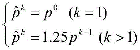
步骤S401、根据下式计算第k个时间节点水力裂缝内预估流体压力;Step S401, calculating the estimated fluid pressure in the hydraulic fracture at the kth time node according to the following formula;

式中:p0为初始时刻水力裂缝内流体压力,MPa;pk-1为第(k-1)时刻水力裂缝内的实际流体压力;
步骤S402、根据上述计算得到的预估流体压力和下式计算第k个时间节点水力裂缝各单元体的预估宽度;Step S402, calculating the estimated width of each unit body of the hydraulic fracture at the kth time node according to the estimated fluid pressure obtained by the above calculation and the following formula;

式中:

步骤S403、通过下式计算预估宽度的误差α;Step S403, calculate the error α of the estimated width by the following formula;

式中:

步骤S404、设定求解精度ε,将上述得到的误差α与求解精度ε进行比较;Step S404, set the solution accuracy ε, and compare the obtained error α with the solution accuracy ε;
若α≤ε,则步骤S402和步骤S403中计算得到的

式中:ε为求解精度;
进一步的技术方案是,所述步骤S50的计算公式为:A further technical solution is that the calculation formula of the step S50 is:
式中:


进一步的技术方案是,所述上侧、下侧天然裂缝入口单元体相对于水力裂缝单元体i的形状系数通过以下步骤得到;A further technical solution is that the shape coefficients of the upper and lower natural fracture inlet unit bodies relative to the hydraulic fracture unit body i are obtained through the following steps;
(4)以第1个水力裂缝单元体中心点为原点,以水力裂缝长度方向为X轴,以过原点且垂直于水力裂缝壁面方向为Y轴,建立全局坐标系;(4) Taking the center point of the first hydraulic fracture unit body as the origin, taking the length direction of the hydraulic fracture as the X axis, and taking the direction passing through the origin and perpendicular to the wall surface of the hydraulic fracture as the Y axis, establish a global coordinate system;
(5)上侧和下侧天然裂缝入口单元体中点在全局坐标系中的坐标可表示为:(5) The coordinates of the upper and lower natural fracture entrance unit midpoints in the global coordinate system can be expressed as:

式中:


(6)上侧和下侧天然裂缝入口单元体中点在以水力裂缝单元体i中点为基准的局部坐标系中的坐标可表示为:(6) The coordinates of the midpoints of the upper and lower natural fracture entrance unit bodies in the local coordinate system based on the midpoint of the hydraulic fracture unit body i can be expressed as:

式中:xui,yui为在局部坐标系中,上侧天然裂缝入口单元体中点坐标;xli,yli为在局部坐标系中,下侧天然裂缝入口单元体中点坐标;

(4)再将步骤(3)中的公式带入到下式中求解得到上侧、下侧天然裂缝入口单元体相对于水力裂缝单元体i的形状系数;(4) The formula in step (3) is then brought into the following formula to solve to obtain the shape coefficients of the upper and lower natural fracture inlet units relative to the hydraulic fracture unit i;
Cij=2G[-f1+yij(f2sin2γij-f3cos2γij)]C ij =2G[-f 1 +y ij (f 2 sin2γ ij -f 3 cos2γ ij )]

式中:

本发明具有以下优点:本发明原理可靠,计算精度高,能够精确计算出缝内暂堵转向压裂过程中天然裂缝的开启时机,进而为压裂方案设计提供有效指导。The invention has the following advantages: the invention has reliable principle and high calculation accuracy, and can accurately calculate the opening timing of natural fractures in the process of temporary plugging and diverting fracturing in fractures, thereby providing effective guidance for fracturing plan design.
附图说明Description of drawings
图1为本发明的流程框图。FIG. 1 is a flow chart of the present invention.
具体实施方式Detailed ways
下面结合实施例和附图对本发明做更进一步的说明。The present invention will be further described below with reference to the embodiments and accompanying drawings.
本发明的一种缝内暂堵条件下天然裂缝开启时机的获取方法,包括以下步骤:A method for obtaining the opening timing of natural fractures under the condition of temporary plugging in fractures of the present invention comprises the following steps:
步骤S10、根据现场地质资料得到地层物性参数,并测得水力裂缝的缝长L;Step S10, obtaining formation physical property parameters according to the on-site geological data, and measuring the fracture length L of the hydraulic fracture;
步骤S20、再将水力裂缝划分为长度相等的N个单元体并依次编号,即每个单元体的长度为L/N;同时以缝内暂堵时刻作为初始时刻t0,将总计算时间t划分为间隔相同的m个时间节点,相邻时间节点的间隔时间为t/m;Step S20, divide the hydraulic fracture into N units of equal length and number them in sequence, that is, the length of each unit is L/N; at the same time, the moment of temporary plugging in the fracture is taken as the initial time t 0 , and the total calculation time t is It is divided into m time nodes with the same interval, and the interval time between adjacent time nodes is t/m;
步骤S30、根据下式计算初始时刻水力裂缝内各个单元体的宽度;Step S30, calculating the width of each unit body in the hydraulic fracture at the initial moment according to the following formula;

式中:p0为初始时刻水力裂缝内流体压力,MPa;σh为地层最小水平主应力,MPa;G为地层岩石剪切模量,MPa;υ为地层岩石泊松比,无因次;L为水力裂缝总长度,m;N为水力裂缝所划分的单元体数量,个;dij为裂缝单元i与裂缝单元j中点之间的距离,m;H为水力裂缝高度,m;α,β分别为经验系数,取α=1,β=2.3;i,j为水力裂缝单元体编号;
步骤S40、计算第k个时间节点水力裂缝内流体压力,其具体为:Step S40, calculating the fluid pressure in the hydraulic fracture at the kth time node, which is specifically:
步骤S401、根据下式计算第k个时间节点水力裂缝内预估流体压力;Step S401, calculating the estimated fluid pressure in the hydraulic fracture at the kth time node according to the following formula;

式中:p0为初始时刻水力裂缝内流体压力,MPa;pk-1为第(k-1)时刻水力裂缝内的实际流体压力;
步骤S402、根据上述计算得到的预估流体压力和下式计算第k个时间节点水力裂缝各单元体的预估宽度;Step S402, calculating the estimated width of each unit body of the hydraulic fracture at the kth time node according to the estimated fluid pressure obtained by the above calculation and the following formula;

式中:

步骤S403、通过下式计算预估宽度的误差α;Step S403, calculate the error α of the estimated width by the following formula;

式中:

步骤S404、设定求解精度ε,将上述得到的误差α与求解精度ε进行比较;Step S404, set the solution accuracy ε, and compare the obtained error α with the solution accuracy ε;
求解精度一般取5%,这个求解精度主要是看求解过程中对于结果精度的要求,求解出的裂缝宽度越接近真实值,误差α就越小,如果没满足求解精度值就需要继续迭代;The solution accuracy is generally 5%. This solution accuracy mainly depends on the requirements for the accuracy of the results in the solution process. The closer the solved crack width is to the real value, the smaller the error α. If the solution accuracy value is not met, it is necessary to continue to iterate;
若α≤ε,则步骤S402和步骤S403中计算得到的

式中:ε为求解精度;
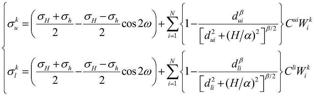
步骤S50、再通过以下公式计算第k个时间节点水力裂缝上、下两侧天然裂缝入口处所受闭合应力;Step S50: Calculate the closing stress at the entrance of the natural fracture on the upper and lower sides of the hydraulic fracture at the kth time node by the following formula;

式中:

σH为地层最大水平主应力,MPa;σh为地层最小水平主应力,MPa;ω为水力裂缝与天然裂缝之间的夹角,度;dui为上侧天然裂缝入口单元中点与水力裂缝单元i中点之间的距离,m;dli为下侧天然裂缝入口单元中点与水力裂缝单元i中点之间的距离,m;H为水力裂缝高度,m;α,β为经验系数,取α=1,β=2.3;
上述上侧、下侧天然裂缝入口单元体相对于水力裂缝单元体i的形状系数通过以下步骤得到;The shape coefficients of the above-mentioned upper and lower natural fracture inlet unit bodies relative to the hydraulic fracture unit body i are obtained through the following steps;
步骤S501、以第1个水力裂缝单元体中心点为原点,以水力裂缝长度方向为X轴,以过原点且垂直于水力裂缝壁面方向为Y轴,建立全局坐标系;Step S501, establishing a global coordinate system with the center point of the first hydraulic fracture unit body as the origin, the length direction of the hydraulic fracture as the X-axis, and the direction passing through the origin and perpendicular to the hydraulic fracture wall as the Y-axis;
步骤S502、上侧和下侧天然裂缝入口单元体中点在全局坐标系中的坐标可表示为:In step S502, the coordinates of the midpoints of the upper and lower natural fracture entrance unit bodies in the global coordinate system can be expressed as:

式中:


步骤S503、上侧和下侧天然裂缝入口单元体中点在以水力裂缝单元体i中点为基准的局部坐标系中的坐标可表示为:In step S503, the coordinates of the midpoints of the upper and lower natural fracture entrance unit bodies in the local coordinate system based on the midpoint of the hydraulic fracture unit body i can be expressed as:

式中:xui,yui为在局部坐标系中,上侧天然裂缝入口单元体中点坐标;xli,yli为在局部坐标系中,下侧天然裂缝入口单元体中点坐标;

步骤S504、再将步骤(3)中的公式带入到下式中求解得到上侧、下侧天然裂缝入口单元体相对于水力裂缝单元体i的形状系数;Step S504, then bring the formula in step (3) into the following formula to solve to obtain the shape coefficients of the upper and lower natural fracture inlet unit bodies relative to the hydraulic fracture unit body i;
Cij=2G[-f1+yij(f2sin2γij-f3cos2γij)]C ij =2G[-f 1 +y ij (f 2 sin2γ ij -f 3 cos2γ ij )]

式中:

步骤S60、基于上述步骤S40和S50的计算结果,通过以下判断准则进行判断天然裂缝是否开启;Step S60, based on the calculation results of the above-mentioned steps S40 and S50, determine whether the natural fractures are opened through the following judgment criteria;
若开启,则时间节点k所对应的时刻t0+kt/m就是天然裂缝的开启时刻;If it is opened, the time t 0 +kt/m corresponding to the time node k is the opening time of the natural fracture;
若未开启,则令k=k+1,重复步骤S40-S50,直至天然裂缝开启或暂堵段失效;If it is not opened, set k=k+1, and repeat steps S40-S50 until the natural fracture is opened or the temporary plugging section fails;
所述判断准则为:The judgment criteria are:

式中:Pk为第k个时间节点水力裂缝内流体压力,MPa;

本实施例中初始时刻水力裂缝内各个单元体宽度计算公式的根据以下步骤得到:In this embodiment, the calculation formula for the width of each unit in the hydraulic fracture at the initial moment is obtained according to the following steps:
1)初始时刻水力裂缝各单元体的宽度与其内部流体压力之间的关系式可表示为:1) The relationship between the width of each unit body of hydraulic fracture and its internal fluid pressure at the initial moment can be expressed as:

Cij=2G[-f1+yij(f2sin2γij-f3cos2γij)] (2)C ij =2G[-f 1 +y ij (f 2 sin2γ ij -f 3 cos2γ ij )] (2)

式中:

2)由于水力裂缝总是趋向于沿垂直于最小水平主应力方向延伸,裂缝单元j在外部将受最小水平主应力作用,在内部将受流体压力作用,因此其所受正应力可表示为:2) Since hydraulic fractures always tend to extend in the direction perpendicular to the minimum horizontal principal stress, the fracture unit j will be affected by the minimum horizontal principal stress externally, and will be affected by fluid pressure internally, so its normal stress can be expressed as:

式中:p0为初始时刻水力裂缝内流体压力,由暂堵剂实际泵注过程所决定,MPa;σh为地层最小水平主应力,MPa;In the formula: p 0 is the fluid pressure in the hydraulic fracture at the initial time, which is determined by the actual pumping process of the temporary plugging agent, MPa; σ h is the minimum horizontal principal stress of the formation, MPa;
2)以第1个水力裂缝单元中心点为原点,以水力裂缝长度方向为X轴,以过原点且垂直于水力裂缝壁面方向为Y轴,建立全局二维直角坐标系;基于此坐标系,第i个水力裂缝单元中点的坐标可表示为:2) With the center point of the first hydraulic fracture unit as the origin, the length direction of the hydraulic fracture as the X-axis, and the direction passing through the origin and perpendicular to the hydraulic fracture wall as the Y-axis, establish a global two-dimensional Cartesian coordinate system; based on this coordinate system, The coordinates of the midpoint of the i-th hydraulic fracture unit can be expressed as:

式中:
3)根据局部坐标与全局坐标之间的变换规律,裂缝单元j中点在以裂缝单元i中点为基准的局部坐标系中的坐标可表示为:3) According to the transformation law between local coordinates and global coordinates, the coordinates of the midpoint of fracture unit j in the local coordinate system based on the midpoint of fracture unit i can be expressed as:

式中:xij,yij为裂缝单元j中点在以裂缝单元i中点为基准的局部坐标系中的坐标值;i,j为水力裂缝单元体编号;L为水力裂缝总长度,m;N为水力裂缝所划分的单元体数量,个。In the formula: x ij , y ij are the coordinate values of the midpoint of fracture unit j in the local coordinate system based on the midpoint of fracture unit i; i, j are the unit numbers of hydraulic fractures; L is the total length of hydraulic fractures, m ; N is the number of units divided by hydraulic fractures.
4)将式(4)代入式(1),式(6)代入式(2)、式(3),即可得到初始时刻水力裂缝内各单元体的宽度

本实施例中第k个时间节点水力裂缝上、下两侧天然裂缝入口处所受闭合应力的计算公式由以下步骤得到:In this embodiment, the calculation formula of the closing stress at the entrance of the natural fracture on the upper and lower sides of the hydraulic fracture at the kth time node is obtained by the following steps:
首先,水力裂缝上侧和下侧天然裂缝是指同一条天然裂缝的两翼,水力裂缝一般从天然裂缝中间部位穿过,从而将原本连续的天然裂缝一分为二,天然裂缝的两翼分别位于水力裂缝两侧(此处用上侧和下侧加以区分)。当水力裂缝与天然裂缝正交时,根据对称性,两侧天然裂缝将同时开启;当水力裂缝与天然裂缝非正交时,两侧天然裂缝具有开启先后顺序,因此在确定暂堵后天然裂缝开启时机时,还需要同步判断是哪一侧天然裂缝优先发生开启,此过程对于天然裂缝开启时机的确定非常重要。First of all, the natural fractures on the upper side and the lower side of the hydraulic fracture refer to the two wings of the same natural fracture. The hydraulic fracture generally passes through the middle of the natural fracture, thereby dividing the originally continuous natural fracture into two. The two wings of the natural fracture are located in the hydraulic fracture. Both sides of the crack (here distinguished by the upper and lower sides). When the hydraulic fractures are orthogonal to the natural fractures, according to the symmetry, the natural fractures on both sides will open at the same time; when the hydraulic fractures are not orthogonal to the natural fractures, the natural fractures on both sides have the sequence of opening, so after the temporary plugging is determined, the natural fractures will be opened at the same time. When opening the timing, it is also necessary to simultaneously determine which side of the natural fractures will open first. This process is very important for determining the timing of opening natural fractures.
类似地,为保证计算统一性和适应数值求解的需要,两侧天然裂缝也将被视为由长度为L/N的多个单元体组成,但计算过程只针对两侧天然裂缝入口处的第一个单元体进行。另外,水力裂缝周围一般存在着大量天然裂缝,此处以仅存在一条天然裂缝情况为例来说明求解过程,当存在多条天然裂缝时整体计算方法类似。Similarly, in order to ensure the uniformity of calculation and meet the needs of numerical solution, the natural fractures on both sides will also be considered to be composed of multiple units of length L/N, but the calculation process is only for the first part at the entrance of the natural fractures on both sides. carried out in a single unit. In addition, there are generally a large number of natural fractures around hydraulic fractures. Here, the solution process is illustrated by taking the case of only one natural fracture as an example. When there are multiple natural fractures, the overall calculation method is similar.
其次,天然裂缝所受闭合应力是指迫使天然裂缝保持闭合状态的作用力,可分为地层正应力和水力裂缝诱导应力两个部分,其中地层正应力部分可表示为:Secondly, the closing stress of natural fractures refers to the force that forces natural fractures to remain closed, which can be divided into two parts: formation normal stress and hydraulic fracture-induced stress, of which the formation normal stress can be expressed as:

式中:
σH——地层最大水平主应力,MPa;σ H ——the maximum horizontal principal stress of the formation, MPa;
σh——地层最小水平主应力,MPa;σ h ——minimum horizontal principal stress of formation, MPa;
ω——水力裂缝与天然裂缝之间的夹角,度。ω——The angle between the hydraulic fracture and the natural fracture, degrees.
水力裂缝诱导应力部分仍然采用式(7)表示,将式(7)与式(8)相叠加,即可得到下式:The stress induced by hydraulic fractures is still represented by formula (7). By superimposing formula (7) and formula (8), the following formula can be obtained:

式中:


以上所述,并非对本发明作任何形式上的限制,虽然本发明已通过上述实施例揭示,然而并非用以限定本发明,任何熟悉本专业的技术人员,在不脱离本发明技术方案范围内,当可利用上述揭示的技术内容作出些变动或修饰为等同变化的等效实施例,但凡是未脱离本发明技术方案的内容,依据本发明的技术实质对以上实施例所作的任何简单修改、等同变化与修饰,均仍属于本发明技术方案的范围内。The above is not intended to limit the present invention in any form. Although the present invention has been disclosed through the above-mentioned embodiments, it is not intended to limit the present invention. Any person skilled in the art, within the scope of the technical solution of the present invention, When the technical contents disclosed above can be used to make some changes or modifications to equivalent embodiments with equivalent changes, any simple modifications or equivalents to the above embodiments according to the technical essence of the present invention do not depart from the content of the technical solution of the present invention. Changes and modifications still fall within the scope of the technical solutions of the present invention.
Claims (5)


Priority Applications (2)
| Application Number | Priority Date | Filing Date | Title |
|---|---|---|---|
| CN201910387470.0A CN110185427B (en) | 2019-05-10 | 2019-05-10 | Method for acquiring natural crack opening time under condition of temporary plugging in crack |
| US16/550,336 US10844710B1 (en) | 2019-05-10 | 2019-08-26 | Method for acquiring opening timing of natural fracture under in-slit temporary plugging condition |
Applications Claiming Priority (1)
| Application Number | Priority Date | Filing Date | Title |
|---|---|---|---|
| CN201910387470.0A CN110185427B (en) | 2019-05-10 | 2019-05-10 | Method for acquiring natural crack opening time under condition of temporary plugging in crack |
Publications (2)
| Publication Number | Publication Date |
|---|---|
| CN110185427A CN110185427A (en) | 2019-08-30 |
| CN110185427B true CN110185427B (en) | 2020-06-30 |
Family
ID=67714328
Family Applications (1)
| Application Number | Title | Priority Date | Filing Date |
|---|---|---|---|
| CN201910387470.0A Active CN110185427B (en) | 2019-05-10 | 2019-05-10 | Method for acquiring natural crack opening time under condition of temporary plugging in crack |
Country Status (2)
| Country | Link |
|---|---|
| US (1) | US10844710B1 (en) |
| CN (1) | CN110185427B (en) |
Families Citing this family (9)
| Publication number | Priority date | Publication date | Assignee | Title |
|---|---|---|---|---|
| CN111379537B (en) * | 2020-03-20 | 2021-04-13 | 西南石油大学 | A method for quantitatively evaluating the plugging strength of temporary plugging agents |
| CN112033812B (en) * | 2020-08-12 | 2022-11-08 | 成都北方石油勘探开发技术有限公司 | Method and system for testing shear-swelling flow conductivity of hydraulic shear fracturing |
| CN112065351B (en) * | 2020-08-25 | 2021-09-17 | 中国石油大学(北京) | Integrated determination method, device and equipment for temporary plugging body information in hydraulic fracture |
| CN114592840B (en) * | 2020-12-04 | 2023-10-27 | 中国石油天然气股份有限公司 | Temporary plugging fracturing method and its application |
| CN114592823B (en) * | 2020-12-04 | 2024-06-25 | 中国石油天然气股份有限公司 | Determination method and application of temporary plugging and diversion material dosage |
| CN114924332B (en) * | 2022-05-30 | 2025-02-07 | 中国矿业大学 | A dynamic evaluation method for the opening and closing of lamellae |
| CN115387755B (en) * | 2022-08-09 | 2023-06-30 | 中国石油大学(华东) | CO (carbon monoxide) 2 Temporary plugging method for leakage along fault during geological storage |
| CN115680559B (en) * | 2022-11-08 | 2023-08-08 | 西南石油大学 | A formula optimization and design method for leak plugging in fractured reservoirs based on pressure dispersion |
| CN116297626B (en) * | 2023-01-31 | 2025-07-11 | 南通大学 | A test method and analysis method for frost heave expansion of closed internal cracks in transparent rock mass |
Citations (5)
| Publication number | Priority date | Publication date | Assignee | Title |
|---|---|---|---|---|
| CN106777663A (en) * | 2016-12-12 | 2017-05-31 | 西南石油大学 | A kind of fracturing fluid leak speed calculation method for considering intrinsic fracture |
| CN107313773A (en) * | 2017-08-31 | 2017-11-03 | 中国石油化工股份有限公司 | It is a kind of to determine method of the interior temporarily stall of seam to required plugging strength |
| CN107609258A (en) * | 2017-09-07 | 2018-01-19 | 西南石油大学 | A kind of shale refracturing turns to the computational methods of fracture initiation pressure |
| CN108805365A (en) * | 2018-07-05 | 2018-11-13 | 西南石油大学 | A kind of heterogeneous shale reservoir crack-induced stress prediction method |
| CN109505576A (en) * | 2017-09-13 | 2019-03-22 | 中国石油化工股份有限公司 | Shale hydraulic fracturing Three-dimensional full coupling discrete fracture network analogy method and system |
Family Cites Families (4)
| Publication number | Priority date | Publication date | Assignee | Title |
|---|---|---|---|---|
| US4850431A (en) * | 1988-05-06 | 1989-07-25 | Halliburton Company | Method of forming a plurality of spaced substantially parallel fractures from a deviated well bore |
| US7066284B2 (en) * | 2001-11-14 | 2006-06-27 | Halliburton Energy Services, Inc. | Method and apparatus for a monodiameter wellbore, monodiameter casing, monobore, and/or monowell |
| WO2011081665A1 (en) * | 2009-12-28 | 2011-07-07 | Enis Ben M | Sequestering co2 and releasing natural gas from coal and gas shale formations |
| WO2017173329A1 (en) * | 2016-04-01 | 2017-10-05 | Board Of Regents Of The Nevada System Of Higher Education, On Behalf Of The University Of Nevada, Reno | Systems and methods for enhancing energy extraction from geothermal wells |
-
2019
- 2019-05-10 CN CN201910387470.0A patent/CN110185427B/en active Active
- 2019-08-26 US US16/550,336 patent/US10844710B1/en not_active Expired - Fee Related
Patent Citations (5)
| Publication number | Priority date | Publication date | Assignee | Title |
|---|---|---|---|---|
| CN106777663A (en) * | 2016-12-12 | 2017-05-31 | 西南石油大学 | A kind of fracturing fluid leak speed calculation method for considering intrinsic fracture |
| CN107313773A (en) * | 2017-08-31 | 2017-11-03 | 中国石油化工股份有限公司 | It is a kind of to determine method of the interior temporarily stall of seam to required plugging strength |
| CN107609258A (en) * | 2017-09-07 | 2018-01-19 | 西南石油大学 | A kind of shale refracturing turns to the computational methods of fracture initiation pressure |
| CN109505576A (en) * | 2017-09-13 | 2019-03-22 | 中国石油化工股份有限公司 | Shale hydraulic fracturing Three-dimensional full coupling discrete fracture network analogy method and system |
| CN108805365A (en) * | 2018-07-05 | 2018-11-13 | 西南石油大学 | A kind of heterogeneous shale reservoir crack-induced stress prediction method |
Non-Patent Citations (2)
| Title |
|---|
| How Natural Fractures Could Affect Hydraulic-Fracture Geometry;Arash Dahi-Taleghanl等;《SPE Journal》;20140228;第161-171页 * |
| Numerical Modeling of Multistranded-Hydraulic-Fracture Propagation:Accounting for the Interaction Between Induced and Natural Fractures;Arash Dahi-Taleghani等;《SPE Journal》;20110930;第575-581页 * |
Also Published As
| Publication number | Publication date |
|---|---|
| US20200355069A1 (en) | 2020-11-12 |
| US10844710B1 (en) | 2020-11-24 |
| CN110185427A (en) | 2019-08-30 |
Similar Documents
| Publication | Publication Date | Title |
|---|---|---|
| CN110185427B (en) | Method for acquiring natural crack opening time under condition of temporary plugging in crack | |
| CN113821953B (en) | Design method of temporary plugging and refracturing based on dynamic in-situ stress and residual oil characteristics | |
| Warpinski | Measurement of width and pressure in a propagating hydraulic fracture | |
| CN104040110B (en) | Hydraulic fracturing interaction modeling in complicated pressure break network | |
| CN106874544B (en) | A kind of geology characterizing method of shale reservoir transformation volume | |
| CN109033504B (en) | Oil-water well casing damage prediction method | |
| CN104747180B (en) | A kind of fracture-pore reservoir for waterflooding extraction analyzes method and application thereof | |
| CN109374867B (en) | A discrete element based hydraulic fracturing simulation method for glutenite | |
| CN106869896A (en) | A kind of Low permeable oil and gas reservoirs straight well volume fracturing reservoir reconstruction method for predicting volume | |
| CN108681635A (en) | A method for evaluating the fracability of tight reservoir volume fracturing | |
| CN105735960A (en) | Cluster interval optimizing method for segmental multi-cluster fracturing of horizontal well of low-permeability oil and gas reservoir | |
| CN111125905B (en) | Two-dimensional fracture network expansion model for coupling oil reservoir fluid flow and simulation method thereof | |
| CN112541287A (en) | Loose sandstone fracturing filling sand control production increase and profile control integrated design method | |
| CN110147561A (en) | A kind of oil and gas reservoir volume fracturing of densification containing intrinsic fracture seam net prediction technique | |
| CN107366530A (en) | A kind of deep layer shale gas reservoir method for increasing and its application | |
| CN106649963A (en) | Determining method of volume fracturing complex seaming net average fracture length and equivalent fracture numbers | |
| CN114810012B (en) | Simulation method for drainage and gas recovery measures of wellbore-formation integrated tight gas reservoirs | |
| CN111963164A (en) | Borehole wall collapse pressure evaluation method for multi-fracture development reservoir | |
| CN1511219A (en) | Method of Controlling the Propagation Direction of Injected Fractures in Permeable Formation | |
| Yu et al. | On how asymmetric stimulated rock volume in shales may impact casing integrity | |
| CN118068399B (en) | A method, equipment, medium, and product for quantitatively evaluating the lateral sealing capacity of faults. | |
| CN114592840B (en) | Temporary plugging fracturing method and its application | |
| CN106408208A (en) | Volume fracturing reforestation effect evaluation method | |
| CN106777663A (en) | A kind of fracturing fluid leak speed calculation method for considering intrinsic fracture | |
| CN114169204B (en) | A method for determining sand control timing for offshore oil and gas field development and production |
Legal Events
| Date | Code | Title | Description |
|---|---|---|---|
| PB01 | Publication | ||
| PB01 | Publication | ||
| SE01 | Entry into force of request for substantive examination | ||
| SE01 | Entry into force of request for substantive examination | ||
| GR01 | Patent grant | ||
| GR01 | Patent grant | ||
| EE01 | Entry into force of recordation of patent licensing contract |
Application publication date: 20190830 Assignee: CHENGDU LEARN-PRACTICES TECHNOLOGY Co.,Ltd. Assignor: SOUTHWEST PETROLEUM University Contract record no.: X2023980040276 Denomination of invention: A Method for Obtaining the Opening Time of Natural Cracks under Temporary Sealing Conditions Granted publication date: 20200630 License type: Common License Record date: 20230825 |
|
| EE01 | Entry into force of recordation of patent licensing contract | ||
| OL01 | Intention to license declared | ||
| OL01 | Intention to license declared |