Disclosure of Invention
It would be advantageous to implement a retrofit light emitting diode, LED, tube suitable for many types of ballasts that may be connected thereto and a lighting system including such a retrofit LED tube. There is also a need to implement a method of operating a retrofit LED tube so that the retrofit LED tube is suitable for a variety of different types of ballasts.
To better address one or more of these issues, in a first aspect of the present disclosure, a retrofit light emitting diode, LED, tube for replacing a fluorescent tube is presented. A retrofit LED tube is arranged to be connected to the ballast, wherein the retrofit LED tube comprises:
-an array of LEDs for emitting light;
-a configurable matching circuit for controlling, when connected, input power from a connected ballast towards said LED array;
-a power rectifier having an input connected to said matching circuit and an output connected to said LED array, wherein said power rectifier is arranged to: receiving an AC supply voltage at an input thereof, converting the AC supply voltage to a DC voltage, and providing the DC voltage to the LED array via an output thereof;
-a ballast determination unit arranged for identifying the type of ballast connected to the retrofit LED tube by:
-controlling the output voltage of said power rectifier to a first voltage and measuring a first current provided by said power rectifier;
-controlling said output voltage of said power rectifier to a second voltage and measuring a second current provided by said power rectifier, wherein said second voltage is different from said first voltage;
-determining the type of said ballast based on said first and second output voltages and said first and second measured currents;
wherein the ballast determination unit is further arranged to configure the configurable matching circuit based on the determined type of the ballast.
The inventors have realized that the ballast may have a detectable current change whenever the output voltage of the power rectifier changes. That is, the characteristics of the output voltage of the power rectifier to the current provided by the power rectifier are different for each type of ballast. This difference may be detected (i.e. measured) by the ballast determination unit and subsequently the configurable matching circuit may be fully configured based on the detection.
One aspect of the present disclosure is to better address the matching of the power input to the ballast to the power delivered to the retrofit LED tube. This improves the efficiency of the ballast and/or retrofit LED tube.
To this end, the inventors have found that the matching circuit should be configured based on the type of ballast to which it is connected. This can ensure that there is no power mismatch by, for example, reflecting power from the matching circuit back to the ballast.
The above-mentioned characteristics of the current and voltage delivered by the power rectifier can be detected using at least two measurement points. In a first measurement point, a first output voltage of the power rectifier is set and a corresponding current provided by the power rectifier is measured. In a second measurement point, a second output voltage of the power rectifier is set and the corresponding current provided by the power rectifier is measured. Based on these two measurement points, a sufficient estimate can be made of the type of ballast that is connected to the retrofit LED tube.
In this case, no communication is required between the ballast and the retrofit LED tube. This means that the ballast does not need to actively communicate with the retrofit LED tube. The ballast need not provide details about its characteristics. The retrofit LED tube is able to determine what type of ballast it is connected to and, therefore, is able to adjust the matching circuit afterwards.
It should be noted that there are different types of ballasts that can be connected to retrofit LED tubes, for example, electronic ballasts, high frequency electronic ballasts, self-oscillating HF ballasts, magnetic ballasts, digital ballasts, and integrated circuit IC controlled ballasts.
The electronic ballast can regulate the amount of current within the lamp through the electronic circuitry. Electronic ballasts, sometimes referred to as control mechanisms, are typically arranged to limit the current flowing in the circuit so that the current is substantially maintained at a level that prevents lamp burn-out. These types of ballasts can operate in either parallel or serial mode. Preferably, a serial mode is used, since in this case, failure of a single lamp does not interrupt the operation of all other lamps. Another type of ballast is a high frequency ballast. Such ballasts typically use frequencies above 20 kHz.
Another type of ballast is a magnetic ballast that employs a core transformer and a coil transformer to operate the lamp. These types of ballasts are arranged to control current and flow at the appropriate levels of the lamp. While these types of ballasts are the simplest, they are characterized by greater robustness.
The retrofit LED tube includes a power rectifier so that the LED tube is used as a replacement for a conventional fluorescent tube. The power rectifier is arranged to receive an AC mains voltage at its input, to convert the AC mains voltage to a DC voltage, and to provide the DC voltage to the LED array via its output. There are different types of rectifiers, each of which is suitable for use in a retrofit LED tube according to the present disclosure. For example, a half-wave rectifier only allows the negative part of the AC supply voltage to pass through, while the positive part of the AC supply voltage is blocked. This is typically done using a single diode. In another example, a full-wave rectifier converts the full AC mains voltage to one of a constant polarity at its output. The positive part of the AC supply voltage is allowed to pass and the negative part of the AC supply voltage is converted into a positive part. This can be done using a bridge rectifier or using two diodes in combination with a switch.
It should be noted that according to the present disclosure, the ballast determination unit may be implemented in a hardware-only method, in a hardware and software method, or in a software-only method. The use of analog and digital hardware components alone results in a hardware-only approach, which will be explained in more detail with respect to the figures. A combined hardware and software approach is preferred because microcontrollers and the like are typically already present in retrofit LED tubes.
It should be noted that the configurable matching circuit may be implemented in various ways in accordance with the present disclosure. For example, capacitors, resistors and/or inductors may be switched in or out so that the impedance of the matching circuit may be adjusted. Alternatively, or in addition, variable capacitors, resistors, or inductors may be used, wherein the variability of these components may be configured to match the impedance of the matching circuit to that type of ballast.
It should be noted that the ballast determination unit may sense the current in various ways in accordance with the present disclosure. For example, digital circuitry may be provided for actively sensing current from the ballast. Another option is to use a resistor in the current path to achieve a voltage drop indicative of the current from the ballast.
In an embodiment, the ballast determination unit is further arranged to bypass the configurable matching circuit during the identification of the type of ballast.
An advantage of this embodiment is that the type of ballast can be evaluated more accurately. The matching network may disturb the output voltage of the power rectifier and may disturb the current provided by the power rectifier. By bypassing the matching circuit, this disturbance no longer exists. This means that the type of ballast connected to the retrofit LED tube can be determined more reliably.
In another embodiment, the configurable matching circuit comprises two matching circuits:
-a first matching circuit matched to the self-oscillating ballast, and
-a second matching circuit matched to a ballast controlled by the integrated circuit IC,
wherein the ballast determination unit is arranged to select one of the two matching circuits based on the determined type of the ballast.
The inventors have found that ballasts can generally be classified into two main groups. The first group relates to self-oscillating ballasts and the second group relates to integrated circuit IC controlled ballasts.
The basic concept behind this is that self-oscillating ballasts have a relatively larger current variation to changes in load voltage compared to IC-controlled ballasts.
In another embodiment, the ballast determination unit comprises a predefined current threshold, wherein the ballast determination unit is arranged to:
-determining that said ballast type is a self-oscillating ballast, if a current difference between said first current and said second current exceeds said predefined current threshold, and
-determining that said type of ballast is an IC controlled ballast, in case the current difference between said first current and said second current is below said predefined current threshold.
As mentioned above, the type of ballast connected to the retrofit LED tube may be derived from the voltage-current characteristics provided by the ballast (and thus also by the power rectifier). To determine the voltage-current characteristic, at least two measurement points are carried out. The voltage-current characteristic may be based on a linear dependency, an exponential dependency or a logarithmic dependency.
In case the current difference between the first current and the second current exceeds a predefined current threshold, it is assumed that the current is not completely stationary within the voltage range. This means that we are dealing with self-oscillating ballasts because they are less able to correct for these variations in output voltage/load.
In another embodiment, the ballast determination unit is arranged to control said output voltage of said power rectifier by adapting a load at said output of said power rectifier.
This has the advantage that the load at the output of the power rectifier can be easily adjusted. For example, the load of the power rectifier may be shorted so that the load is momentarily near zero. This may be achieved by providing a switch on the output of the power rectifier to momentarily short out its output.
In a further embodiment, the ballast determination unit is arranged for identifying the type of said ballast connected to said retrofit LED tube by:
-short-circuiting said output of said power rectifier and measuring said first current provided by said power rectifier;
-enabling said LED array such that said LED array emits light and measuring said second current provided by said power rectifier;
-determining the type of said ballast based on said first and second output voltages and said first and second measured currents.
An advantage of the above described embodiment is that it provides a simple but efficient way of generating two measurement points. The first measurement point relates to a situation in which the output of the power rectifier is short-circuited (i.e., the voltage output of the power rectifier is close to zero). The second measurement point relates to the case where the LED is emitting light. The comparison of the currents delivered in the two measuring points is an indication of the type of the ballast connected to the retrofit LED tube.
In another embodiment, the ballast determination unit is further arranged for identifying the type of said ballast connected to said retrofit LED tube by:
-controlling the output voltage of said power rectifier to a third voltage and measuring a third current provided by said power rectifier;
-determining the type of said ballast based on said first, second and third output voltages and said measured first, second and third currents.
In case a third measurement is performed, the accuracy of determining the type of ballast may be further increased. That is, a third measurement point is created to better estimate the current difference provided at the multiple voltage reference points. In this case, a more accurate voltage-current characteristic can be evaluated, which results in an improvement in the detection of the type of the ballast.
In a second aspect of the present disclosure, a method of operating a retrofit LED tube according to any of the preceding claims is provided, wherein the above method comprises the steps of:
-controlling said output voltage of said power rectifier to said first voltage and measuring said first current provided by said power rectifier by said ballast determination unit;
-controlling, by said ballast determination unit, said output voltage of said power rectifier to said second voltage and measuring said second current provided by said power rectifier, wherein said second voltage is different from said first voltage;
-determining, by said ballast determination unit, a type of said ballast based on said first and second output voltages and said first and second measured currents;
-configuring, by the ballast determination unit, the configurable matching circuit based on the determined type of the ballast.
It should be noted that the advantages and definitions disclosed in relation to the embodiments of the first aspect of the invention (i.e. the modified LED tube) also correspond to the embodiments of the second aspect of the invention (i.e. the method of operating such a modified LED tube), respectively.
The proposed method may be performed each time the retrofit LED tube is switched on, or may be performed once for the retrofit LED tube.
In one embodiment, the method comprises the initial steps of:
-bypassing said configurable matching circuit by said ballast determination unit.
In another embodiment, the step of configuring comprises:
-selecting, by the ballast determination unit, one of the two matching circuits based on the determined type of the ballast.
In another embodiment, the step of determining comprises:
-determining by said ballast determination unit that said type of ballast is a self-oscillating ballast, if the current difference between said first current and said second current exceeds said predefined current threshold, and
-determining by said ballast determination unit that said type of ballast is an IC controlled ballast, if the current difference between said first current and said second current is below said predefined current threshold.
In one embodiment, the step of controlling comprises adapting a load at said output of said power rectifier.
In another embodiment, the above method comprises the steps of:
-short-circuiting, by said ballast determination unit, said output of said power rectifier and measuring said first current provided by said power rectifier;
-enabling, by said ballast determination unit, said LED array such that said LED array emits light and measuring said second current provided by said power rectifier;
-determining, by the ballast determination unit, the type of the ballast based on the first and second output voltages and the measured first and second currents.
In yet another embodiment, the method comprises the steps of:
-controlling, by said ballast determination unit, the output voltage of said power rectifier to a third voltage and measuring said third current provided by said power rectifier;
-determining, by the ballast determination unit, the type of the ballast based on the first, second and third output voltages and the measured first, second and third currents.
In a third aspect, the invention provides a computer program product comprising a readable storage medium comprising instructions which, when executed on at least one processor, cause the at least one processor to perform a method according to any one of the embodiments disclosed above.
It should be noted that the advantages and definitions disclosed with respect to the embodiments of the first and second aspect of the invention, respectively (i.e. the modified LED tube and the method), also correspond to the embodiments of the third aspect of the invention, respectively (i.e. the computer program product).
In a fourth aspect, the present invention provides a lighting system comprising:
-a retrofit LED tube according to any of the embodiments disclosed above, and
-a ballast, wherein said ballast is connected to said retrofit LED tube.
The method may be efficiently performed by a suitably programmed processor or programmable controller, such as a microprocessor or microcontroller provided with a solid state light source.
These and other aspects of the invention are apparent from and will be elucidated with reference to the embodiment(s) described hereinafter.
Detailed Description
Fig. 1 shows a voltage-current characteristic 1 of a self-oscillating ballast. Here, the vertical axis 2 represents the current in amperes provided by the ballast to the retrofit LED tube. The current depicted on the vertical axis is also a measure of the current output by the power rectifier. In a practical embodiment, the current provided by the power rectifier is easier to determine/measure than the current provided by the ballast.
The horizontal axis 3 represents the voltage of the LED array. Here, it is apparent that the current provided by the ballast decreases each time the voltage increases. This is a typical characteristic of self-oscillating ballasts that is commonly observed. The control loop of a self-oscillating ballast is typically not powerful and fast enough to quickly correct for voltage variations.
Fig. 2 shows the voltage-current characteristic 11 of an integrated circuit IC-controlled ballast. Here, the vertical axis 12 represents the current provided by the ballast to the retrofit LED tube in amperes. The current depicted on the vertical axis is also a measure of the current output by the power rectifier. In a practical embodiment, the current provided by the power rectifier is easier to determine/measure than the current provided by the ballast.
The horizontal axis 13 represents the voltage of the LED array. Here, it is apparent that the current provided by the ballast is approximately the same whenever the voltage increases. This is a typical characteristic of IC controlled ballasts that is commonly observed. The control loop of an IC controlled ballast is typically more powerful and/or faster than the control loop of a self-oscillating ballast.
It should be noted that the voltage-current characteristics marked with reference numerals 1 and 11 each consist of several measurement points. For example, the voltage-current characteristic shown in fig. 1 is composed of six measurement points, which are indicated by diamonds. The lines between the diamonds are connecting lines so that the measuring points are connected to each other. From the above, the connecting lines form interpolation points that can also be used according to the present disclosure. This will be described in detail later with respect to fig. 3. The voltage-current characteristic 11 of fig. 2 shows four measurement points, each indicated with a specific diamond. Likewise, the connecting lines connecting the four diamonds form interpolation points that may also be used in accordance with the present disclosure, as will be described in more detail with respect to FIG. 3.
Fig. 3 shows a simplified block diagram of a lighting system 21 according to the present disclosure.
The lighting system 21 comprises a high frequency ballast 22 and a retrofit LED tube. The retrofit LED tube comprises building blocks as indicated with reference numerals 23, 24, 25, 26, 27, 28, 29, 30, 31, 32 and 33. It should be noted that the high frequency ballast 22 may be of any type in accordance with the present disclosure. Preferably, the high frequency ballast 22 is a self-oscillating ballast or an IC controlled oscillator.
The retrofit LED tube is arranged in a single housing. The housing is arranged to accommodate each building frame as shown above. For example, the housing may be a light-transmissive housing or a partially light-transmissive housing configured as a retrofit light tube type.
The term "retrofit" also defines some mechanical aspects of the LED tube. That is, the LED tube is retrofit in case it is adapted to a conventional armature of a fluorescent tube (e.g., a fluorescent tube adapted to T5, T12, etc.). To accommodate these conventional armatures, the modified LED tube includes conductive pins for connecting and supporting the modified LED tube in the conventional armatures.
Therefore, retrofit LED tubes are used in place of fluorescent tubes. The retrofit LED tube is thus suitable for armatures that are commonly used for fluorescent tubes.
The retrofit LED tube comprises an LED array comprising a plurality of LEDs 28 for emitting light, wherein the plurality of LEDs may be divided into a plurality of parallel branches. The use of multiple branches makes it possible to drive each LED in a branch in a different way. For example, the LEDs in the first branch may be driven such that they emit light at their maximum capacity, while the LEDs in the second branch are driven such that they do not emit any light at all.
Further, those skilled in the art will recognize that in one practical embodiment, the LEDs are evenly distributed over the length of the tube and evenly spaced to provide as uniform illumination as possible through the LED tube throughout its length. The present disclosure is not limited to any particular type of LED nor to LEDs of any color. Generally, white LEDs are used.
The retrofit LED lamp tube further comprises a filament emulation circuit 23. Filament emulation circuits are commonly used to prevent ballasts from entering a protection mode. This fault detection mode of the ballast is active during the enablement of the retrofit LED tube (i.e., during the lamp identification phase). After the lamp identification phase (i.e., during the steady state phase), the filament is generally of little use. Thus, the filament emulation circuit 23 is typically only used to emulate the ballast 22 to which the fluorescent tube is connected.
Further, configurable matching circuits 24, 25 are provided for controlling the input power from the connected ballast 22 towards the LED array 28. Matching circuits are typically used to substantially match the input impedance of the electrical load to the output impedance of the ballast 22, thereby increasing power transfer between the ballast 22 to the retrofit LED tube and/or reducing signal reflections from the load.
In this case, the configurable matching circuits 24, 25 comprise two separate matching circuits. The first matching circuit is indicated with reference numeral 24 and relates to matching the output impedance of the self-oscillating ballast. The second matching circuit is indicated with reference numeral 25 and relates to matching the output impedance of the IC controlled ballast.
It should be noted that in this example, the configurable matching circuit comprises two separate matching circuits. However, it is also contemplated to provide a configurable matching circuit and additional components, such as capacitors and/or indications, based on the detected activation or deactivation of the type of ballast.
A power rectifier 27 is provided, which power rectifier 27 is depicted as an LED driver 27 in this example. A power rectifier 27 has an input connected to the configurable matching circuit and has an output connected to an LED array 28. The power rectifier 27 is arranged to convert the AC mains voltage to a DC voltage and to provide the DC voltage to the LED array 28.
Further, a ballast determination unit is provided, identified with reference numerals 29, 30, 31, 32 and 33. The ballast determination units 29, 30, 31, 32 and 33 comprise a load adapter 29, a current monitor 31, a voltage monitor 33 and a network selector 32.
The ballast determination unit is arranged for identifying the type of ballast 22 connected to the retrofit LED tube by:
-controlling the output voltage of said power rectifier to a first voltage and measuring a first current provided by said power rectifier;
-controlling said output voltage of said power rectifier to a second voltage and measuring a second current provided by said power rectifier, wherein said second voltage is different from said first voltage;
-determining the type of said ballast based on said first and second output voltages and said first and second measured currents;
wherein the above-mentioned ballast determination unit 29, 30, 31, 32, 33 is further arranged to configure the above-mentioned configurable matching circuit 24, 25 based on the determined type of the above-mentioned ballast.
It should be noted that the current monitor 31 monitors (i.e., measures) the current provided by the power rectifier 27. The current may be measured at a plurality of reference points in the retrofit LED tube. For example, the current may be measured directly at the output of the power rectifier. In some cases, the current may also be detected at the LED array, i.e., the current flowing through the LED array.
Further, the voltage monitor 33 monitors (i.e., measures) the output voltage of the power rectifier. The measured voltage and the measured current provide a measurement point. The measurement points may be compared to the characteristics disclosed with respect to fig. 1 and 2 to determine which type of ballast is connected to the retrofit LED tube.
In this case, the retrofit LED tube comprises a bypass switch 26 that bypasses the configurable matching circuit 24, 25 during the identification of the type of ballast.
The bypass switch is, for example, a metal oxide semiconductor MOS field effect transistor FET placed in parallel with the configurable matching circuit 24, 25.
This means that no matching circuit is present when identifying the type of ballast. This is advantageous because in this case the type of ballast can be determined more accurately. Once the type of ballast has been determined, the network selector 32 selects either the first matching circuit 24 or the second matching circuit 25. This means that either the first matching circuit 24 or the second matching circuit 25 is connected to the ballast 22.
As an alternative, the configurable matching circuit 24, 25 may be composed of several components, and depending on the type of ballast 22 selected, one or more of these components may be enabled to form a matching circuit specific to the detected type of ballast 22.
As mentioned above, the load adapter 29 may be arranged to control the output voltage of the above-mentioned power rectifier to a first voltage and to measure a first current provided by the above-mentioned power rectifier. For example, the load adapter 29 may modify the load at the output of the power rectifier 27, for example, to a short circuit or full load condition.
The block diagram depicted in fig. 3 may be implemented using a hardware-only approach or a combined hardware/software approach. Preferably, a hardware-software combination method is used, as this is advantageous for the accuracy of the measurement, and as this is advantageous for the size of each component.
For example, the network selector 32, the current monitor 31, and/or the voltage monitor 33 may each be any type of hardware (such as a microprocessor, microcontroller, field programmable gate array, FPGA, or the like). The components may be authorized via the AC mains voltage in combination with the power rectifier, or may be authorized using an auxiliary power supply such as a battery. A microprocessor may be provided that includes functionality for implementing each of these blocks.
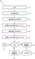
Fig. 4 shows a simplified flow diagram 51 of a method according to the present disclosure.
The method involves operating a retrofit LED tube according to any of the embodiments disclosed above.
In a first step, the retrofit LED tube may be reset so that the type of ballast is unknown. As such, if the retrofit LED tube has just been released from the manufacturing facility, the retrofit LED tube is constructed in this manner.
In the next step, the bypass switch is enabled, so that both matching circuits are bypassed 53. Then, the determination of the type of the ballast is performed during the bypassing of the matching circuit.
In a subsequent step, the load of the power rectifier is modified so that the power rectifier provides a low output voltage 54. For example, the output of the power rectifier is shorted.
In another step, the current and voltage are measured 55 to determine a first measurement point associated with the particular setting (i.e., associated with the setting specific to the load being set).
The load of the power rectifier is then adjusted 56 again so that the power rectifier provides a relatively high output voltage. This can be achieved by, for example, switching on the LEDs of the LED array. The current and output voltage are then measured 57 again to determine a second measurement point associated with that particular setting (i.e., associated with a setting specific to the load being set).
In this particular case, the ballast determination unit comprises a predefined current threshold 58.
If the current difference between the first measurement point and the second measurement point is less than the current threshold, the IC controlled ballast is determined 62. If the current difference between the first measurement point and the second measurement point is greater than the current threshold, a self-oscillating ballast is determined 60. Finally, bypass 61 is disabled so that the determined and selected matching circuits are enabled.
Other variations to the disclosed embodiments can be understood and effected by those skilled in the art in practicing the claimed invention, from a study of the drawings, the disclosure, and the appended claims. In the claims, the word "comprising" does not exclude other elements or steps, and the indefinite article "a" or "an" does not exclude a plurality. A single processor or other unit may fulfill the functions of several items recited in the claims. The mere fact that certain measures are recited in mutually different dependent claims does not indicate that a combination of these measures cannot be used to advantage. A computer program may be stored/distributed on a suitable medium, such as an optical storage medium or a solid-state medium supplied together with or as part of other hardware, but may also be distributed in other forms, such as via the internet or other wired or wireless telecommunication systems. Any reference signs in the claims should not be construed as limiting their scope.