Detailed Description
The technical solutions in the embodiments of the present invention will be clearly and completely described below with reference to the drawings in the embodiments of the present invention, and it is obvious that the described embodiments are only a part of the embodiments of the present invention, and not all of the embodiments. The components of embodiments of the present invention generally described and illustrated in the figures herein may be arranged and designed in a wide variety of different configurations. Thus, the following detailed description of the embodiments of the present invention, presented in the figures, is not intended to limit the scope of the invention, as claimed, but is merely representative of selected embodiments of the invention. All other embodiments, which can be derived by a person skilled in the art from the embodiments of the present invention without making any creative effort, shall fall within the protection scope of the present invention.
Some embodiments of the invention are described in detail below with reference to the accompanying drawings. The embodiments described below and the features of the embodiments can be combined with each other without conflict.
Example 1
With the continuous development of wireless communication technology, various communication systems have higher and higher requirements for broadband, and in order to expand the bandwidth of an antenna, at least one parasitic element is often arranged around the antenna, and the at least one parasitic element cannot exist independently, coexists with a corresponding antenna, and is electromagnetically coupled with the corresponding antenna to realize a parasitic function, i.e., the parasitic function is to reduce the operating frequency of the antenna, expand the bandwidth of the antenna, form multiple frequency bands, and the like.
The parasitic elements are arranged around the corresponding antenna at positions close to the corresponding antenna and can be arranged in a predetermined manner. The specific position of the parasitic element is set according to the radiation performance of the antenna, for example, based on the maximum impedance bandwidth that can be realized between the parasitic element and the corresponding antenna, the coupling distance corresponding to the maximum impedance bandwidth can be one of the bases for setting the parasitic element. The parasitic element can be a metal sheet, the metal sheet is electromagnetically coupled with the corresponding antenna, the influence generated after the electromagnetic coupling can be equivalent to capacitance and inductance connected in series or in parallel, the capacitance and the inductance are regarded as excitation except for the antenna corresponding to the parasitic element, so that secondary radiation is generated, the radiation effect of the antenna corresponding to the parasitic element and the secondary radiation effect are superposed on a magnetic field, the original electromagnetic field structure is changed, the electromagnetic field is strengthened in a certain direction, and the gain of the antenna corresponding to the parasitic element is increased.
Although the parasitic element has the function of expanding the bandwidth of the corresponding antenna, the parasitic element itself does not have an independent antenna function, and can only depend on the coexistence of the corresponding antennas and work in the working frequency band of the corresponding antennas. In a scene with a high requirement on the coverage rate of the antenna, the coverage rate is often improved by setting a plurality of antennas with different main lobe directions, however, although the coverage rate of the antenna is improved by this method, hardware devices corresponding to the antennas are relatively increased, the size of the antenna is correspondingly increased, and under the development trend that the terminal is increasingly lighter and thinner, the antenna design is challenged greatly.
Therefore, in view of the above situation, a solution for multiplexing a parasitic element corresponding to an antenna is proposed, in which, under the condition that the parasitic function of the parasitic element with respect to the corresponding antenna is not affected, the parasitic element is further provided with an independent antenna function, so as to form an independent antenna device coexisting with the corresponding antenna.
The compact antenna comprises at least one parasitic element corresponding to the predetermined antenna. And a feeding point is arranged in at least one parasitic element, and the corresponding parasitic element is fed through the feeding point so that the parasitic element has an independent antenna function.
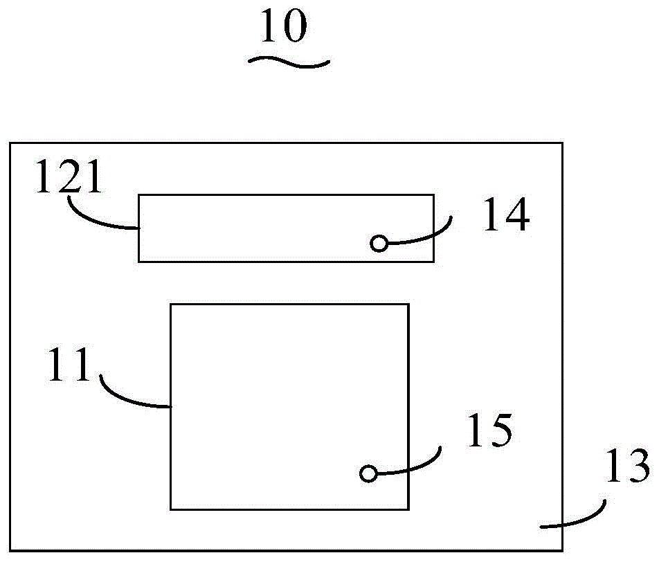
As an aspect of the compact antenna 10, as shown in fig. 1, the compact antenna 10 includes a predetermined antenna 11, and a first parasitic element 121 corresponding to the predetermined antenna 11.
The first parasitic element 121 is disposed close to the predetermined antenna 11, and the specific position may be determined according to the requirement. The first parasitic element 121 may be a metal sheet, and is electromagnetically coupled to the corresponding predetermined antenna 11, so as to widen the frequency band of the predetermined antenna 11.
The predetermined antenna 11 is provided with a first feeding point 15, and the radio frequency operating frequency of the predetermined antenna 11 is determined by tuning the predetermined antenna 11 by adjusting the position and feeding mode of the first feeding point 15.
The first parasitic element 121 is provided with a second feeding point 14, and the second feeding point 14 is fed through a feeding network, so that the first parasitic element 121 is fed, so that the first parasitic element 121 forms a first antenna with a radio frequency function, at this time, the first parasitic element 121 not only has a parasitic function, but also has an independent antenna function, and the first parasitic element 121 is reused as a first antenna to receive and transmit radio frequency signals. In other words, the predetermined antenna 11 and the first parasitic element 121 both have the function of independent antennas, improving the radiation performance of the compact antenna 10.
Specifically, after the rf operating frequency band of the predetermined antenna 11 is determined, the directional pattern of the first parasitic element 121 corresponding to the predetermined antenna 11 can be determined according to the coverage area of the compact antenna 10 and the directional pattern of the predetermined antenna 11.
After the rf operating band of the first parasitic element 121 is determined, the second feeding point 14 on the first parasitic element 121 is fed through the feeding network.
Further, after feeding the second feeding point 14, the first parasitic element 121 where the second feeding point 14 is located is made to have a function of an independent antenna.
Further, the coverage of the compact antenna 10 is improved by tuning structural parameters between the predetermined antenna 11 and the first parasitic element 121, such that the predetermined antenna 11 and the second feeding point 14 correspond to the first parasitic element 121 and operate in the same frequency band range, and a directional pattern of the predetermined antenna and a directional pattern of the first parasitic element 121 have complementarity, where the structural parameters include a distance between the predetermined antenna 11 and the second feeding point 14 corresponding to the first parasitic element 121, a position of the second feeding point 14, a feeding manner to the second feeding point 14, a shape of the first parasitic element 121, a size of the first parasitic element 121, and the like.
In particular, said second feeding point 14 is fed through a feeding network. The feed network may include devices such as a matching circuit, a power divider, and a phase shifter. The matching circuit may include a capacitance, inductance, or other tuning device.
The position of the second feeding point 14, the feeding mode to the second feeding point 14, the distance between the predetermined antenna 11 and the first parasitic element 121, the shape of the first parasitic element 121, the size of the first parasitic element 121, and other structural parameters are continuously adjusted, so that the value of a device such as a capacitor or an inductor in the matching circuit is continuously changed, the matching circuit, the power divider and the phase shifter are further used together to change the respective antenna impedances of the predetermined antenna 11 and the first parasitic element 121, and on the basis that the respective antenna impedances are matched with the impedance of the feeder line and the currents on the antenna are balanced, the respective directional patterns of the predetermined antenna 11 and the first parasitic element 121 have complementarity, and the best radiation performance is achieved.
The feeding manner may include a parallel feeding manner, a coaxial feeding manner, and the like.
Further, the predetermined antenna 11 is a patch antenna, and the antenna formed by the first parasitic element 121 provided with the feeding point is a monopole antenna.
In this embodiment, in order to make the compact antenna 10 better meet practical and radiation requirements, the first parasitic element 121 is rectangular. In some other embodiments, the first parasitic element 121 may also be a circle, a trapezoid, or a triangle, which is not limited herein, depending on the antenna layout structure, the practical requirements, and the antenna radiation performance.
In this embodiment, the compact antenna 10 is a millimeter wave antenna, and the millimeter wave refers to electromagnetic waves of 24250 MHz-52600 MHz specified by the 5G standard, and may be extended to a higher frequency band with the change of the 5G standard in the future.
Further, the compact antenna 10 further includes a substrate 13, and the substrate 13 provides a carrier for the compact antenna 10, that is, the predetermined antenna, all parasitic units corresponding to the predetermined antenna, and the feeding network are all disposed on the substrate 13.
Further, the substrate 13 may also be configured as a rectangle, a square, a circle, a trapezoid, a triangle, etc. according to the scene requirement and the radiation requirement, and the specific shape is determined as the case may be.
Furthermore, a ground of the antenna with the rf function formed by the predetermined antenna 11 and the first parasitic element 121 is disposed on one side of the substrate 13, and the antenna with the rf function formed by the predetermined antenna 11 and the first parasitic element 121 is grounded to prevent static electricity, lightning strike and interference.
As another alternative to the compact antenna 10, as shown in fig. 2, the compact antenna 10 includes a predetermined antenna 11 and a first parasitic element 121 corresponding to the predetermined antenna 11.
The second feeding point 14 is disposed on the first parasitic element 121, and the first parasitic element 121 is fed through the second feeding point 14, so that the first parasitic element 121 forms a first antenna with a radio frequency function, and at this time, the first parasitic element 121 not only has a parasitic function, but also has an independent antenna function.
The predetermined antenna 11 is provided with two feeding points, i.e., a first feeding point 15 and a sixth feeding point 151. The predetermined antenna 11 is fed through the two feeding points, so that the predetermined antenna realizes dual polarization, and the number of the antennas is saved.
In the present embodiment, only the first parasitic element 121 is multiplexed on the predetermined antenna 11, and the first parasitic element is fed to form a first antenna having an independent antenna function. And the predetermined antenna 11 and the first parasitic element 121 are tuned by adjusting the structural parameters, such as the positions of the first feeding point 15 and the sixth feeding point 151 of the predetermined antenna 11, the position of the second feeding point 14 in the first parasitic element 121, the feeding modes of the first feeding point 15 and the sixth feeding point 151, the feeding mode of the second feeding point 14 in the first parasitic element 121, the distance between the predetermined antenna 11 and the first parasitic element 121, the size of the first parasitic element 121, and the shape of the first parasitic element 121, so that the predetermined antenna 11 and the first parasitic element 121 operate in the same frequency band range, and the directional pattern of the predetermined antenna 11 and the directional pattern of the first parasitic element 121 have complementarity.
As another embodiment of the compact antenna 10, as shown in fig. 3, the compact antenna 10 includes a predetermined antenna 11 and a first parasitic element 121 and a second parasitic element 122 corresponding to the predetermined antenna 11.
The second feeding point 14 is disposed on the first parasitic element 121, and the first parasitic element 121 is fed through the second feeding point 14, so that the first parasitic element 121 forms a first antenna with a radio frequency function, and at this time, the first parasitic element 121 not only has a parasitic function, but also has an independent antenna function.
The third feeding point 16 is disposed on the second parasitic element 122, and the second parasitic element 122 is fed through the third feeding point 16, so that the second parasitic element 122 forms a second antenna with a radio frequency function, and at this time, the second parasitic element 122 not only has a parasitic function, but also has an independent antenna function.
In this embodiment, the first parasitic element 121 and the second parasitic element 122 are multiplexed at the same time, and are fed separately to form a first antenna and a second antenna with a radio frequency function. And the predetermined antenna 11, the first antenna and the second antenna are tuned by adjusting the position and the feeding mode of the first feeding point 15, the position and the feeding mode of the second feeding point 14, the position and the feeding mode of the third feeding point 16, the distance between the predetermined antenna 11 and the first parasitic element 121, the distance between the predetermined antenna 11 and the second parasitic element 122, the distance between the first parasitic element 121 and the second parasitic element 122, the shapes of the first parasitic element 121 and the second parasitic element 122, and the sizes of the first parasitic element 121 and the second parasitic element 122, so that the predetermined antenna 11, the first antenna and the second antenna operate in the same frequency band range, and the directional diagram of the predetermined antenna 11, the directional diagram of the first antenna and the directional diagram of the second antenna have complementarity.
Further, for convenience of antenna layout, the plurality of parasitic elements may be symmetrically disposed with respect to the predetermined antenna 11, such as the first parasitic element 121 and the second parasitic element 122 in fig. 3.
Further, all feeding points may be fed through the same feeding network. The feed network comprises a power divider, a phase shifter and the like.
In this embodiment, in order to reduce the antenna hardware cost, the first feeding point 15, the second feeding point 14, and the third feeding point 16 may be fed through the same feeding network. In some other embodiments, each feeding point may also be fed independently through a different feeding network.
In this embodiment, the shapes and sizes of the plurality of parasitic elements are the same. In some other embodiments, the shapes and sizes of the parasitic elements are different, depending on the hardware design requirements and the radiation performance of the compact antenna 10.
As another embodiment of the compact antenna 10, as shown in fig. 4, the compact antenna 10 includes a predetermined antenna 11 and a first parasitic element 121 and a second parasitic element 122 corresponding to the predetermined antenna 11.
In order to facilitate the hardware layout of the compact antenna 10, if the predetermined antenna 11 is a patch antenna, the patch antenna includes four side surfaces, and when the number of the parasitic elements is less than four, for example, three parasitic elements may be disposed on any three side surfaces of the patch antenna, or two of the parasitic elements are disposed symmetrically with respect to the patch antenna, and the other parasitic element is disposed on any one side surface of the other two side surfaces; for another example, the two parasitic elements may be symmetrically disposed with respect to the patch antenna, or may be disposed on any two sides of the patch antenna. When the number of the parasitic elements is equal to four, the four parasitic elements may be disposed two by two symmetrically with respect to the patch antenna.
In this embodiment, the first parasitic element 121 and the second parasitic element 122 are distributed on two adjacent sides of the predetermined antenna 11. In this scheme, the first parasitic element 121 and the second parasitic element 122 are multiplexed at the same time, and are fed separately to form a first antenna and a second antenna with a radio frequency function. And the predetermined antenna 11, the first antenna and the second antenna are tuned by adjusting the position and the feeding mode of the first feeding point 15, the position and the feeding mode of the second feeding point 14, the position and the feeding mode of the third feeding point 16, the distance between the predetermined antenna 11 and the first parasitic element 121, the distance between the predetermined antenna 11 and the second parasitic element 122, the distance between the first parasitic element 121 and the second parasitic element 122, the shapes of the first parasitic element 121 and the second parasitic element 122, and the sizes of the first parasitic element 121 and the second parasitic element 122, so that the predetermined antenna 11, the first antenna and the second antenna operate in the same frequency band range, and the directional diagram of the predetermined antenna 11, the directional diagram of the first antenna and the directional diagram of the second antenna have complementarity.
Further, if the predetermined antenna 11 corresponds to a plurality of parasitic elements, a predetermined number of feeding points are set in a predetermined number of parasitic elements of the plurality of parasitic elements, and the predetermined number of feeding points are fed, so that the predetermined number of parasitic elements form a corresponding predetermined number of antennas with independent antenna functions.
As another alternative to the compact antenna 10, as shown in fig. 5, the compact antenna 10 includes a predetermined antenna 11 and a first parasitic element 121, a second parasitic element 122, a third parasitic element 123 and a fourth parasitic element 124 corresponding to the predetermined antenna 11.
When the predetermined number is 2, a second feeding point 14 is provided at the first parasitic element 121, and the first parasitic element 121 is fed by the second feeding point 14, so that the first parasitic element 121 forms a first antenna with a radio frequency function, and at this time, the first parasitic element 121 not only has a parasitic function, but also has an independent antenna function.
The third feeding point 16 is disposed on the second parasitic element 122, and the second parasitic element 122 is fed through the third feeding point 16, so that the second parasitic element 122 forms a second antenna with an independent antenna function, and at this time, the second parasitic element 122 not only has a parasitic function, but also has an independent antenna function. The third parasitic element 123 and the fourth parasitic element 124 do not feed, and only have a parasitic function.
In this embodiment, the first parasitic element 121 and the second parasitic element 122 are multiplexed at the same time, and are fed separately to form a first antenna and a second antenna having independent antenna functions. Meanwhile, the first parasitic element 121, the second parasitic element 122, the third parasitic element 123 and the fourth parasitic element 124 also have parasitic effects, so that the bandwidth of the compact antenna is widened, and the coverage rate of the compact antenna 10 is improved.
The predetermined antenna 11, the first antenna and the second antenna are tuned by adjusting structural parameters such as the position and the feeding mode of the first feeding point 15, the position and the feeding mode of the second feeding point 14, the position and the feeding mode of the third feeding point 16, the distance between the predetermined antenna 11 and the first parasitic element 121, the distance between the predetermined antenna 11 and the second parasitic element 122, the distance between the predetermined antenna 11 and the third parasitic element 123, the distance between the predetermined antenna 11 and the fourth parasitic element 124, the size of each parasitic element, the shape of each parasitic element and the distance between each parasitic element, so that the predetermined antenna 11, the first antenna and the second antenna operate in the same frequency band range, and the directional diagram of the predetermined antenna 11, the directional diagram of the first antenna and the directional diagram of the second antenna have complementarity.
Meanwhile, the first parasitic element 121, the second parasitic element 122, the third parasitic element 123 and the fourth parasitic element 124 also have parasitic effects, so that the bandwidth of the compact antenna is widened, and the coverage rate of the compact antenna 10 is improved.
The predetermined antenna 11 is a patch antenna, and the first antenna and the second antenna are monopole antennas.
In this embodiment, the directional pattern of the compact antenna 10 will be described by taking fig. 6 as an example. As shown in fig. 6a, the pattern is the pattern when the parasitic element in fig. 5 is not changed to a monopole antenna, and the visible signal is perpendicular to the front of the patch antenna, and the coverage on both sides is poor. Fig. 6b and 6c are the directional diagrams of the first antenna and the second antenna, respectively, and it can be seen that the directional diagrams of the first antenna and the second antenna cover the directions of both sides, respectively, and have complementarity with the directional diagram of the patch antenna, so that the spatial coverage performance of the compact antenna is improved.
As shown in fig. 7, a comparison of the S-parameters of the compact antenna 10 and other antennas without the multiplexed parasitic elements is shown. As can be seen from the figure, a curve S1 represents the S parameter | S (1,1) | of the patch antenna without the parasitic element, a curve S2 represents the S parameter | S (1,1) | of the patch antenna with the parasitic element, a curve S3 represents the S parameter | S (1,1) | of the two monopole antennas, and a curve S4 represents the S parameter | S (1,1) | of the compact antenna (the patch antenna and the multiplexed parasitic element as the monopole antenna). The patch antenna in the curve S1 has no parasitic element, and the patch antenna is a single-frequency antenna and does not form multiple frequencies. The curve S2 with the parasitic elements forms multiple frequencies, and the first frequency band is significantly lower than the operating frequency of the curve S1, so that the parasitic elements have the functions of forming multiple frequencies and reducing the rf operating frequency. The two monopole antennas in curve S3 also form multiple frequencies, the first band being significantly higher than the operating frequency of curve S2. In the curve S4, multiple frequencies are formed between the patch antenna and the parasitic element as a monopole, the parasitic element still functions as a monopole, and has a radio frequency function to form multiple frequencies and reduce the radio frequency operating frequency, the frequency of the first frequency band is lower than the frequency of the three curves, and the frequencies of the multiple frequency bands are more stable.
When the predetermined number is 3, as shown in fig. 8, after the first parasitic element 121 is fed by the second feeding point 14 to form a first antenna having an independent antenna function and the second parasitic element 122 is fed by the third feeding point 16 to form a second antenna having an independent antenna function, the fourth feeding point 17 is provided at the third parasitic element 123 and the third parasitic element 123 is fed by the fourth feeding point 17, so that the third parasitic element 123 forms a third antenna having an independent antenna function. The fourth parasitic element 124 does not feed and has only a parasitic function.
In this embodiment, the first parasitic element 121, the second parasitic element 122, and the third parasitic element 123 are multiplexed at the same time, and are fed to form a first antenna, a second antenna, and a third antenna with a radio frequency function.
The predetermined antenna 11, the first antenna, the second antenna and the third antenna are tuned by adjusting structural parameters such as the position and the feeding mode of the first feeding point 15, the position and the feeding mode of the second feeding point 14, the position and the feeding mode of the third feeding point 16, the position and the feeding mode of the fourth feeding point 17, the distance between the predetermined antenna 11 and the first parasitic element 121, the distance between the predetermined antenna 11 and the second parasitic element 122, the distance between the predetermined antenna 11 and the third parasitic element 123, the distance between the predetermined antenna 11 and the fourth parasitic element 124, the size of each parasitic element, the shape of each parasitic element and the distance between each parasitic element, so that the predetermined antenna 11, the first antenna, the second antenna and the third antenna operate in the same frequency band range, and the directional pattern of the predetermined antenna 11, the directional pattern of the first antenna, The directional diagram of the second antenna and the directional diagram of the third antenna have complementarity.
Meanwhile, the first parasitic element 121, the second parasitic element 122, the third parasitic element 123 and the fourth parasitic element 124 also have parasitic effects, so that the bandwidth of the compact antenna is widened, and the coverage rate of the compact antenna 10 is improved.
When the predetermined number is 4, as shown in fig. 9, after the first parasitic element 121 is fed by the second feeding point 14 to form a first antenna having an independent antenna function, the second parasitic element 122 is fed by the third feeding point 16 to form a second antenna having an independent antenna function, and the third parasitic element 123 is fed by the fourth feeding point 17 to form a third antenna having an independent antenna function, the fifth feeding point 18 is provided in the fourth parasitic element 124, and the fourth parasitic element 124 is fed by the fifth feeding point 18, so that the fourth parasitic element 124 forms a fourth antenna having an independent antenna function, and at this time, the fourth parasitic element 124 has not only a parasitic function but also an independent antenna function at the same time.
In this embodiment, the first parasitic element 121, the second parasitic element 122, the third parasitic element 123 and the fourth parasitic element 124 are multiplexed at the same time, and are fed separately to form a first antenna, a second antenna, a third antenna and a fourth antenna with independent antenna functions.
The predetermined antenna 11, the first antenna, the second antenna, the third antenna and the fourth antenna are tuned by adjusting structural parameters such as the position and feeding manner of the first feeding point 15 of the predetermined antenna 11, the position and feeding manner of the second feeding point 14, the position and feeding manner of the third feeding point 16, the position and feeding manner of the fourth feeding point 17, the position and feeding manner of the fifth feeding point 18 of the predetermined antenna 11, the distance between the predetermined antenna 11 and the first parasitic element 121, the distance between the predetermined antenna 11 and the second parasitic element 122, the distance between the predetermined antenna 11 and the third parasitic element 123, the distance between the predetermined antenna 11 and the fourth parasitic element 124, the size of each parasitic element, the shape of each parasitic element and the distance between each parasitic element, so that the predetermined antenna 11, the first antenna, the second antenna, the third antenna and the fourth antenna operate in the same frequency band range, and the directional diagram of the predetermined antenna 11, the directional diagram of the first antenna, the directional diagram of the second antenna, the directional diagram of the third antenna and the directional diagram of the fourth antenna have complementarity.
Meanwhile, the first parasitic element 121, the second parasitic element 122, the third parasitic element 123 and the fourth parasitic element 124 also have parasitic effects, and the bandwidth of the compact antenna is widened. Therefore, the compact antenna 10 has the effects of reducing the hardware cost and size, reducing the operating frequency of a single antenna and the frequency of multiple frequencies, and improving the coverage rate of the compact antenna 10.
Further, in order to overcome the disadvantage of high propagation loss of the electromagnetic wave in the millimeter wave band, as shown in fig. 9, an antenna array 20 is shown, in which the antenna array 20 includes a plurality of compact antennas 10 as described above. The plurality of compact antennas 10 may have a beam scanning function to improve an EIRP (Effective Isotropic Radiated Power) and a spatial coverage of a beam, so as to meet a performance requirement of a millimeter wave band of a 3GPP standard.
It should be noted that the compact antenna 10 in fig. 10 is only schematically illustrated in one configuration, and the compact antenna 10 in the antenna array 20 may also be in any configuration described in the above embodiments.
Further, the compact antenna 10 may be integrated processes such as board level, LTCC (Low Temperature Co-fired Ceramic), semiconductor, etc., and may be in the form of a PCB antenna, a package antenna, an on-chip antenna, etc.
In other embodiments of the present invention, a mobile terminal is also provided, which includes the above-mentioned compact antenna 10 or the above-mentioned antenna array 20. The mobile terminal may further include a memory, an input unit, a display unit, a photographing unit, an audio circuit, a wireless fidelity (WiFi) module, and a power supply. The memory may mainly include a storage program area that may store an operating system, an application program required for at least one function, and a storage data area that may store data created according to use of the mobile terminal; the input unit may include a touch panel and may include other input devices; the display unit may include a display panel; the photographing unit is used for acquiring image information in an imaging range; the audio circuit may provide an audio interface between the user and the mobile terminal; the wireless fidelity module can help users to receive and send e-mails, browse webpages, access streaming media and the like, and provides wireless broadband internet access for users; the main processor is a control center of the mobile terminal, besides the functions, the main processor can also be connected with each part of the whole mobile terminal by various interfaces and lines, and executes various functions and processing data of the mobile terminal by running or executing software programs and/or modules stored in the memory and calling data stored in the memory, thereby integrally monitoring the mobile terminal; the power supply can be logically connected with the processor through the power management system, so that the functions of managing charging, discharging, power consumption management and the like are realized through the power management system. Those skilled in the art will appreciate that the various components described above do not constitute a limitation of mobile terminals that may include more or fewer components, or some components in combination, or a different arrangement of components.
In the embodiments provided in the present application, it should be understood that the disclosed apparatus and method can be implemented in other ways. The apparatus embodiments described above are merely illustrative and, for example, the flowchart and block diagrams in the figures illustrate the architecture, functionality, and operation of possible implementations of apparatus, methods and computer program products according to various embodiments of the present invention. In this regard, each block in the flowchart or block diagrams may represent a module, segment, or portion of code, which comprises one or more executable instructions for implementing the specified logical function(s). It should also be noted that, in alternative implementations, the functions noted in the block may occur out of the order noted in the figures. For example, two blocks shown in succession may, in fact, be executed substantially concurrently, or the blocks may sometimes be executed in the reverse order, depending upon the functionality involved. It will also be noted that each block of the block diagrams and/or flowchart illustration, and combinations of blocks in the block diagrams and/or flowchart illustration, can be implemented by special purpose hardware-based systems which perform the specified functions or acts, or combinations of special purpose hardware and computer instructions.
In addition, each functional module or unit in each embodiment of the present invention may be integrated together to form an independent part, or each module may exist separately, or two or more modules may be integrated to form an independent part.
The above description is only for the specific embodiments of the present invention, but the scope of the present invention is not limited thereto, and any person skilled in the art can easily conceive of the changes or substitutions within the technical scope of the present invention, and all the changes or substitutions should be covered within the scope of the present invention.