This application claims priority from U.S. patent application No. 61/428,299 entitled System Solution For Detection Of systematic on set Of Stroke And Alert, filed on 30.11.2017, the entire contents Of which are incorporated herein by reference.
Detailed Description
Various embodiments of a computer system and computer process for detecting the onset of symptoms of stroke are described herein. The computer system and process can thereby detect the onset of the stroke itself. The computer system may be embodied in a smart wearable device (e.g., a watch, wristband, ring, or glasses). The computer system may alternatively be embodied in a piece of furniture (e.g. a bedside lamp) or monitoring equipment. Other embodiments of the computer system include one or more distributed devices, such as an image capture and audio receiver system located on a bedside table for identifying arm movements, facial placement, and voice of the patient, and a wrist-mounted photoplethysmography (PPG) sensor for monitoring vital signs of the patient.
Computer systems and computer processes result in the monitoring and analysis of vital signs and physical symptoms in order to detect or ascertain whether a patient is likely to experience the onset of a stroke. The computer system and computer program also alerts emergency services if the onset of a stroke is detected or ascertained.
As used herein, the term "vital sign" generally refers to Heart Rate Variability (HRV), although other vital signs, such as pulse rate, respiratory rate, diastolic and/or systolic blood pressure, and temperature, may also be monitored. It will therefore be appreciated that suitable sensors or devices must be used to measure relevant vital signs, such as a heart rate monitor for monitoring heart rate variability and pulse rate, a motion sensor or other device for monitoring respiratory rate, a sphygmomanometer for measuring blood pressure, and a thermometer for measuring temperature.
As used herein, the term "physical symptoms" refers to physical symptoms of stroke onset, such as facial ptosis, speech ambiguity, and/or arm weakness.
As used herein, the term "emergency services" refers to a group that is expected to be able to give help in the event that a patient experiences a stroke. Thus, emergency services may include one or more of the following: ambulance services, a particular patient's caregiver, friend, colleague, close relative, or any other group that is expected to be able to give help in the event that the patient experiences a stroke.
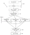
Fig. 1 illustrates a computer process 100 for alerting emergency services. The computer process 100 is implemented by: first monitoring the patient for one or more vital signs, second detecting physical symptoms indicative of the onset of a stroke, and third alerting emergency services if the monitoring and detecting steps indicate the onset of a stroke. Thus, process 100 broadly includes:
step 102: measuring one or more vital signs of a patient;
step 104: comparing the vital signs to a predetermined baseline;
step 106: assessing a physical symptom of the patient; and
step 108: contact for emergency services is initiated.
Calibration phase
In addition to steps 102-108, the illustrative process 100 also includes:
step 110: performing a baseline measurement; and
step 112: a baseline is formed from the measurements.
Steps 110 and 112 provide a calibration phase for calibrating the system 300 and the process 100 implemented by such a system 300. Thus, these steps enable a predetermined baseline to be formed based on previous measurements on the patient, and thus be patient specific. In this context, the term "baseline" includes normal or expected readings of vital signs during normal activity. As will be clear from the context in which the term is used, the term "baseline" also includes normal or expected physical symptoms or features of the patient (i.e., arm movement, facial disposition, and/or personalized speech). In one example, the baseline of the HRV may include expected changes in the HRV for normal activities (e.g., walking, jogging, dishwashing, etc.), which are typically very small changes. Similar baselines may be established for heart rate, physical fitness (which may correspond to changes in vital signs (e.g., heart rate, HRV, blood pressure, and body temperature)), and circadian rhythm.
During the calibration phase, the system 300 monitors or measures a vital sign of the patient, step 110. In one example, the system 300 includes a wearable device mounted to a wrist of a patient. The wearable device continuously measures all parameters necessary to establish a relevant baseline for each vital sign.
The measurements can be processed, calibrated, and fine-tuned against each other and other parameters to form one or more baselines for each vital sign, step 112. For example, when a patient is sleeping or shortly after the patient wakes up, their heart rate or pulse may be lower than the daily average for the particular patient. Over time, particularly during periods of physical activity, the heart rate may be expected to be higher. Typically, a patient will have a relatively consistent daily routine such that exercise, coffee or stimulant consumption, and laxative consumption occur at specific times of the day. Thus, lower and higher baselines may be expected at relatively consistent times of day.
Measuring or monitoring one or more vital signs according to step 110 and correlating these measurements with other parameters (e.g. time of day or relationship to other vital signs) (e.g. an increase in heart rate may be accompanied by an increase in body temperature as the patient performs physical activity), enables the baseline to be adaptive. In other words, the baseline may vary over the course of a day according to the average amount of variation the patient experienced over the course of a normal day. Optionally, different baselines may be established, which represent, for example, the HRV of the patient at different times of the day or during various activities (including inter-beat intervals (IBIs), HRV in the time domain, and/or HRV in the frequency domain).
A threshold value may then be determined for the patient. The threshold is the maximum deviation from the associated baseline that system 300 and process 100 will tolerate before starting to examine a process indicative of a physical symptom of stroke onset (e.g., face, arm, and speech (FAS) step 106 that triggers process 100). The threshold may be very low for some vital signs (e.g., HRV) but may be higher for other vital signs (e.g., pulse rate). For example, the HRV may have a threshold amount of ± 2%, the R-R interval (in the QRS complex) may have a threshold amount of ± 25% (e.g., standard deviation), the blood pressure may have a threshold amount of ± 10%, and the pulse rate may have a threshold amount of ± 15% (or ± 100% to account for the difference between resting heart rate and active heart rate) for each type of activity.
In other cases, the threshold amount may be specified as a particular maximum or minimum value. For example, a maximum heart rate of 180bpm may be set as a baseline, depending on patient characteristics such as age, smoker status, family history of stroke or other disease, and other relevant considerations. The 180bpm heart rate may be set as baseline and the threshold amount may be set to-100 bpm ≦ threshold amount ≦ 180bpm, such that step 106 is performed if the heart rate exceeds the maximum heart rate or falls below 80 bpm. Otherwise, step 106 will not be triggered.
In accordance with the present teachings, medical personnel will recognize the manner in which the baseline and threshold amounts may be set and which are appropriate for the physical symptoms of each vital sign and parameter, such as arm movement, facial placement, and voice.
These vital sign records are stored in a memory, which may be the memory 214 within the system 300, or may be another memory, such as a cloud storage or a remote storage, or a combination thereof.
Similar baselines (i.e., physical symptom baselines) may be established for arm movements, facial placement, and speech. For arm movements, a set of one or more arm movements may be specified. The set of arm movements may reflect a corresponding one or more arm movements that may be used to indicate whether the patient is experiencing the onset of a stroke, such as lifting the arm to a horizontal position when the patient is upright. One or more movements are then recorded (step 110), and the recording is used to form a baseline of physical symptoms for the arm movements (step 112).
For facial arrangements, one or more images of the patient's face may be captured and various measurements made, such as the relative positions of particular features of the patient's face when the patient's face is stationary, when the patient is smiling and/or in various other states (e.g., the distance between the corners of the mouth) along with any differences in the relative positions of the features when in these states (e.g., the distance between each corner of the mouth when stationary as compared to when smiling, or the distance between the left and right corners of the mouth and the left and right eyes, respectively, when stationary and when smiling). Facial measurements are then recorded (step 110), and the recording is used to form a physical symptom baseline for facial placement (step 112).
Similarly, the patient's voice may be recorded, step 110. This may involve specifying a series of words or a section from a book that the patient must read. Speech recognition techniques are well understood and documented. The voice recording can then be used to form a physical symptom baseline for the voice (step 112).
Analysis and calibration are further discussed with reference to fig. 5.
Importantly, steps 110 and 112 are shown in dashed lines because they are optional. Ideally, the baseline is patient-specific, and the previous measurements (from which the baseline was formed) can be made by the computer system 300 described with reference to fig. 3. However, in some instances, a baseline may be established for the group in which the patient is indicated. For example, the patient may be a 46 year old non-smoker with a low activity level and a family history of stroke. A group of individuals from which vital signs and physical measurements are taken, such as non-smokers between the ages of 45 and 50, with low to moderate activity levels, and a family history of stroke, can then be used as a baseline. Further, in some embodiments, baseline measurements (i.e., previous measurements used to formulate a baseline) may be made by an unrelated device and downloaded by the system 300 (e.g., from the internet, the cloud, a doctor's computer, etc.) for use in the process 100.
The measured vital signs-step 102 and step 104-are evaluated against a baseline
Once the baseline is established and the process 100 and system 300 are thereby calibrated, the remaining steps of the process 100 may be implemented. In these, the first step to be performed is step 102 — measuring one or more vital signs of the patient. The measurements made according to step 102 are then compared against a predetermined baseline, step 104.
The manner in which vital signs are measured according to step 102 may depend on the nature of the computer system 300. For example, the computer system 300 may be embodied in a wearable device that is mounted to the wrist of a patient. At the wrist, many of the vascular cavities are close to the skin. The blood vessel lumen of the wrist is readily available for making measurements of pulse and other parameters. The wearable device can continuously monitor and analyze these vascular cavities in order to derive vital signs, such as HRV and pulse rate. Similarly, the computer system 300 may include a ring that measures relevant parameters caused by the motion of the finger to which the ring is attached and caused by the vasodilation and vasoconstriction of blood vessels extending along the finger to which the ring is fitted.
In some embodiments, a PPG sensor is used in computer system 300. The PPG sensor is housed within the housing of the wearable device and is securely attached to the wrist of the patient. The contact face of the PPG sensor directly or indirectly abuts the skin of the patient. It is desirable to use an adhesive mechanism (i.e., an adhesive patch or adhesive patch, which may be a removable or replaceable adhesive patch) in this attachment, rather than a low-friction surface-to-surface contact mechanism, so that the patient's skin adheres at least slightly to the wearable device. The adhesive mechanism provides more consistent contact over the entire contact area between the wearable device and the patient's skin to reduce noise caused by variations in the amount of contact between the wearable device and the patient's skin.
Notably, some tests show that both horizontal and vertical movements of the wrist change vital signs, e.g. HRV, detected by PPG sensors. Similarly, bending of the wrist and rapid movement of the arm may also result in changes in vital sign measurements made using the PPG sensor and in changes in other parts of the patient. These changes may inadvertently cause the patient's vital signs to exceed the relevant baseline as predetermined by step 112-i.e., a false positive is identified-and thus unnecessarily trigger step 106.
Thus, during the calibration phase (steps 110 and 112), the PPG sensor may obtain measurements of the patient's vital signs while the patient performs various wrist movements. As discussed with reference to fig. 5, a series of analysis steps may then be used to compensate for or filter out data errors due to wrist movement. This may be accomplished by correlating wrist motion and motion as detected by the motion sensor (see reference numerals 320 and 322 in fig. 3) with changes in vital signs (e.g., HRV) where such changes are not expected. For example, the patient may be requested to sit or stand still, so that there should be little or no change in HRV or pulse rate. The wearable device then measures one or more vital signs of the patient. The patient then performs a series of arm and wrist movements that may be specified by medical personnel. The wearable device measures the motion of the wearable device and detects changes in one or more vital signs, such that any such detected changes can be attributed to the motion of the wrist. Then, when substantial motion is later detected, the baseline or measurements made at step 102 may be appropriately adjusted to ensure that the patient has not inadvertently failed to complete step 104, which would otherwise result in step 106 having to be performed.
Furthermore, the wearable device may include more than one PPG sensor or other types of sensors as used in other embodiments, such that multiple measurements of each parameter are taken and may be averaged or otherwise calibrated against each other to eliminate noise, such as noise resulting from the effects of gravity or capillary refilling. Additionally or alternatively, the sensors for vital sign measurement may be mounted on a gimbal or motorized component that itself is calibrated using data derived from the motion sensor (e.g., accelerometer) to counteract the effects of motion and keep the vital sign sensor continuously registered at the same location on the patient's skin.
The combination of motion compensation and motion counter balancing using a fixed manner of the array of sensors (e.g., adhesive) reduces noise and thus reduces the likelihood that step 106 is unnecessarily performed.
After filtering and removing noise and errors from the measurements made at step 102, one or more vital signs measured by the computer system 300 are compared to a corresponding baseline, step 104. To assess whether step 106 should be performed, computer system 300 determines whether a predetermined baseline, i.e., the baseline established by steps 110 and 112, has been exceeded. While this may be a one-to-one comparison of the measurements made according to step 102 to a baseline, this will allow the patient's disease to be unchanged from one day to another. Thus, preferably, step 104 involves determining whether the predetermined baseline is exceeded by a threshold amount for each vital sign measured according to step 102. For example, the predetermined baseline for heart rate may be 70 heart beats per minute (bpm), and the threshold amount may be 20%, resulting in a range of 56bpm to 84 bpm. The heart rate measured at step 102 is then compared to a baseline and a predetermined threshold to see if it falls within the range 56bmp to 84bmp (including 56bmp and 84bmp), or if it exceeds that range (i.e. falls outside of that range-either less than 56bmp or greater than 84 bmp).
Assessment of physical symptoms of a patient-step 106
After determining that the predetermined baseline has been exceeded according to step 104, the computer system 300 performs step 106 of assessing the physical condition of the patient. This involves at least one of the following steps:
step 106A: measuring movement of one or both arms of the patient;
step 106B: imaging a facial arrangement of a patient;
step 106C: listening to speech from the patient; and
step 106D: the measurements produced according to the associated ones of steps 106A, 106B, and 106C are compared to corresponding body symptom baselines (e.g., predetermined baseline movements, placements, and speech). For illustrative purposes, in the embodiments described below, all three of steps 106A, 106B, and 106C may be performed, but it is understood that in other embodiments of the present disclosure, only one of these steps may have to be performed.
To ensure that appropriate measurements are taken by which the computer system 300 can evaluate the patient, instructions are communicated to the patient. The instructions advise the patient to perform the necessary arm, facial and/or voice functions, which can be compared to the corresponding physical symptom baseline. In some examples, the computer system 300 includes a display (see, e.g., reference numeral 304 of fig. 3) that visually displays instructions to the patient. The computer system 300 may alternatively or additionally provide audio instructions through a speaker (see, e.g., reference numeral 316 of fig. 3). In some cases, the patient may not know that their vital sign measurements are found to exceed the corresponding baseline, and thus an audio response (e.g., an audible alarm) may be used to attract attention to the computer system 300, and then the computer system 300 presents visual instructions to the patient to facilitate performance of steps 106A, 106B, and/or 106C.
A common symptom of stroke is weakness of the arms. The weakness in the arm is evaluated according to step 106A. To detect weakness of the arm, the patient may be prompted to lift the arm to a predetermined position. In some embodiments (such as those discussed above), the computer system 300 includes a wearable device. The wearable device may be mounted to the arm of the patient, e.g. at the shoulder, upper arm, elbow, for the arm, wrist, finger (e.g. ring). Thus, the motion of the device may be measured and assumed to correspond to the motion of the arm (including the hand) to which the device is attached.
The movement of the arm can be detected in a number of ways. In some embodiments, the wearable device comprises an image capture device (e.g., a camera) that may also be used to detect facial arrangements according to step 106B. Measuring the movement of the arm may thus comprise comparing the position of the arm in successive images captured by the image capturing device. In these cases, the position of the arm may be derived by comparing images of objects other than the arm (e.g., the patient's body, the opposite arm, or any fixed furniture or object in close proximity to the patient) and determining the change in position of the arm from one image to the next by determining the change in position of the image capture device relative to the object. In other embodiments, an external device (e.g., a device that is placed on a table) may capture images of the patient and determine various positions of their arm between successive images.
It is often more accurate to use a motion sensor device housed within wearable computer system 300 than to use image capture to assess or measure arm motion. The motion sensor device may be an accelerometer or other acceleration or vibration sensor so that the movement of the arm may be made directly (i.e. derived from the movement itself rather than by inference, e.g. it may be necessary to derive the arm movement from an image).
Because paralysis resulting from a stroke may not affect the side of the body to which the wearable device is attached (i.e., may not affect the arm (the one arm) of the patient's two arms to which the device is attached), it is desirable for the patient to perform arm elevation with both arms. In some cases, the arms will move together. In other cases, the arms will move one after the other. Thus, the wearable device may include a button (e.g., button 710 as shown in fig. 7) such that the user must first lift one arm, then lift their second arm to the same position, and press the button on the wearable device.
A motion sensor device (e.g., an accelerometer) may measure acceleration, velocity, displacement, offset (e.g., lateral offset), and position of an arm to which a wearable device including a motion sensor is attached. Instead, a motion sensor comprising an image capture device (e.g., side camera 602 in fig. 6) may measure these parameters of both arms. For the arm (the peer arm) to which the computer system 300 is attached, the image capture device may determine its position by referencing other objects, as discussed above. For the other arm (the opposite arm), the image capture device may capture an image of the arm and determine the change in position of the opposite arm between successive images. Thus, an accelerometer or image capture device may be used to determine the movement of the co-lateral arm (including an offset, such as a lateral offset), and the image capture device may also detect the position of the counter-lateral arm. As a result, in some embodiments, an accelerometer and an image capture device are provided. In other embodiments, only an image capture device is provided. In either of these cases, the relative positions of the two arms can be detected. Further, movement of only one arm, or movement of both arms, may be detected, as appropriate in any particular application (e.g., some patients may have only one arm).
Where an image capture device (e.g., camera 320 in fig. 3) is provided, the relative position of one or both arms may be determined from analyzing images of one arm acquired from a computing system 300 attached to the other arm. To accomplish this, the image capture device 320 may be mounted under an angle (from which it can see the contralateral arm and face) so that it can be used for steps 106A and 106B. The image capture device may alternatively be mounted on a pivot to effect rotation about an axis. This allows the camera to be rotated between a position where it faces the opposing arms and a position where it is directed towards the patient's face. The computing device 300 may alternatively include two image capture devices, one mounted to face the opposing arm and the other mounted to capture the patient's face.
The camera may comprise a visible light detection device, such as a standard camera, or may comprise an ultrasonic or infrared sensor, a laser (e.g. laser spot) projector and receiver, etc. -similar comments apply to any camera described with reference to the current figures and defined in the claims. Furthermore, the device may comprise a separate device mounted on each arm, such that image capture may be avoided for arm movement measurement or monitoring.
The computing system 300 may thus be designed to capture the movement of each arm, confirming that both arms have moved to substantially the same position (e.g., by a button press) and relative position between the two arms.
Although there is no fixed order in which steps 106A, 106B, and/or 106C must be performed, in some embodiments in which both steps 106A and 106B are performed, step 106A will be performed before step 106B to ensure that the image capture device (see reference numeral 320 in fig. 3) is positioned laterally outward from the shoulder in order to capture an image of the patient's face.
To image the patient's facial arrangement according to step 106B, the system 300 may provide audio and/or visual commands to the patient (using the speaker 316 and/or display 304 of the computing system 300). These commands may instruct the patient to provide prescribed facial expressions to the computing system 300, the expressions being selected to make facial droop evident or otherwise highlight differences between motions on one side of the face when compared to the other side of the face. For example, the patient may be requested to smile or blink.
As further discussed with reference to fig. 2, the computer process 100 then images the patient's facial arrangement-i.e., it evaluates the relative positions of various facial features. This may include the position of one feature (e.g., the left corner of the mouth) relative to another feature (e.g., the right corner of the mouth) or the relative position of the same feature at the beginning and end of a facial gesture (e.g., the position of the left corner of the mouth when the patient's mouth is in a relaxed state and when the patient's mouth is in a smiling gesture, or the position of the eyelids during a blinking/blinking gesture). These features may include the position of the lips, the corners of the mouth, the nasolabial sulcus, the degree of ptosis or splaying of the eyelids (particularly the upper eyelid), the asymmetry of the frontal muscles, and/or the movement or asymmetry of the zygomatic muscle, the orbicularis oris, the buccinator muscle, the levator labei superior lip in the nose, and/or movement or asymmetry in other features as defined by medical personnel as being likely to be relevant to the assessment of the onset of stroke. Image analysis techniques are well understood in view of the present teachings, and their application will be recognized by the skilled artisan.
With respect to steps 106A and 106B, recitation of a line of speech need not occur at any particular time. If these steps are performed in the relevant embodiment. The voice may be transmitted by the patient before, during, or after these steps, but performing the voice during step 106B may result in the placement of features relating to the position of the mouth failing to conform to the predetermined physical symptom baseline of the facial placement. In any case, to detect the patient's voice, the computing system 300 includes an audio receiver, such as a microphone or audio receiver device 318 (see fig. 3).
The patient can be instructed to recite the predetermined phrase, for example, using audio commands issued from the speaker 316 and/or visual commands issued on the display 304. The predetermined phrases may be designed to emphasize particular sounds, such as sharp "K" and "T" sounds, which are clear indications or ambiguous speech when they are incorrectly pronounced. Phrases may be adapted according to the patient's native language, e.g., "without, and/or but" for an english speaking patient.
The recited passage and/or any other speech captured by the audio receiver may be the same as the passage or speech recorded during calibration steps 110 and 112. During calibration, when step 106C is performed, recordings may be received multiple times and averaged to obtain a total expected sound for future recitations of the same passage. In addition, the change in each recorded deviation from the mean may define a threshold value from the baseline for the intended physical symptom of speech (i.e., the mean of all recitations of the same line of speech).
Step 106C may involve the detection of duration, tone, pitch, and other factors evaluated against the same factors recorded in step 110 and used in constructing a baseline of the predetermined physical symptoms of speech under step 112.
Once the relevant motion in the arm motion is measured, the patient's facial arrangement is imaged and speech is received, the computer system 300 performs step 106D-comparing the data accumulated in the relevant steps in steps 106A, 106B and 106C with the corresponding physical symptom baselines established for these physical parameters, which are predetermined according to steps 110 and 112. Alternatively, step 106D may be performed after each of steps 106A, 106B, and/or 106C, respectively. For example, once the movement of the arms is measured, the movement may be compared to a baseline of arm movement (which may include a baseline of relative arm positions during and after movement of both arms). Similarly, the face arrangement imaged at step 106B may be compared to the relevant face arrangement baseline at step 106D, either before receiving speech according to step 106C or performing arm movements as per step 106A, or simultaneously with the receipt of speech or arm movement measurements.
In either case, for arm movements that exceed a predetermined physical symptom baseline, the movement may take too long to complete, the deviation from the position when complete may be too large when compared to the baseline, the lateral shift during performance of the predetermined movement may be too large, and so on. For facial arrangements that exceed a predetermined physical symptom baseline, the particular relationship between the features (i.e., the relative positions of those features), the time it takes to complete a gesture (e.g., smiling), or the relative starting positions of the features (e.g., eyelid droop when the eyes are open, when compared to the eyelid position when the eyes are open during calibration) may be too far from the physical symptom baseline. Similarly, where the tone, duration, pitch, sound sharpness, and other factors deviate too much from those same amounts measured during calibration, the predetermined physical symptom baseline may be exceeded. In each of these cases, a threshold amount is applied that specifies what is a "too large" deviation of the corresponding measurement from its predetermined physical symptom baseline.
Thus, steps 106A, 106B and/or 106C, and 106D are only performed after the patient fails to complete the vital signs comparison step 104. The same process may be repeated one or more times, for example two additional repetitions-up to three repetitions of the total-to increase the confidence that the patient is indeed experiencing an episode of stroke.
After failing to successfully complete step 104 and/or step 106, computer system 300 assumes that the patient is experiencing an episode of stroke and initiates contact for emergency services (step 108), for example by sending a notification to an emergency services server (which may include the GPS coordinates of computer system 300 and thus the patient to which computer system 300 is attached). In the case where the emergency service provider is a person reachable via a mobile telephone, the server may comprise a mobile telephone telecommunications service provider server and the server routes the notification to the relevant mobile telephone.
Emergency services may be contacted after the first failure of step 106D and further contacted if future executions of steps 104 and 106D show that the first execution is a false alarm, if additional iterations are performed. In other words, emergency services may initially notify of a potential onset of a stroke. This initial notification may then be followed by a cancellation notification if the patient exhibits the appropriate vital signs and motor skills (i.e., arm movement, facial placement, and voice not exceeding a predetermined baseline) in subsequent iterations of steps 104 and 106D. In the event that the patient fails to repeat steps 104 and/or 106D, the initial notification may instead be followed up with confirmation.
The computer system 300 may provide the location of the patient. This may be accomplished by providing GPS coordinates from a GPS device housed within computer system 300. GPS technology is well understood and need not be described in detail. GPS and other geographic location information may help the first responder locate the patient in the event that the patient becomes incapacitated (e.g., the patient loses consciousness). The image capture device in computer system 300 may also be activated to capture visual information of a stroke event.
In some embodiments discussed below, emergency services may also be contacted in the event of a serious adverse event (e.g., a fall or a false action by the patient). Alternatively, as shown in fig. 3, the patient may actively contact emergency services through the device by pressing button 328.
The steps broadly described with reference to fig. 1 are schematically illustrated in fig. 2. At step 202, the process initiates. Initiation may simply include switching the computer system 300 on so that it can monitor vital signs. Generally, any baseline will be predetermined according to steps 110 and 112 before step 202 is performed.
Block 204 provides for a continuous monitoring phase. During the monitoring phase, one or more vital signs are monitored, step 206. Monitoring vital signs is discussed with reference to step 102 of fig. 1. The measurement of vital signs may be performed at regular time intervals. For example, under normal monitoring conditions, pulse readings may be collected at 15 minute intervals.
The measurements are then compared to the respective baseline for each vital sign to determine if there are any abnormalities, i.e., the measurements indicate that the patient's vital sign has exceeded the predetermined baseline, step 208. This comparison step is discussed with reference to step 104 of FIG. 1.
If the measurements of one or more vital signs do not exceed the relevant baseline, the computer system 300 does nothing except to continue monitoring the patient according to step 206. If the measurement of at least one of the one or more vital signs does exceed the relevant baseline, the computer system 300 checks whether emergency services have been alerted (step 210). If the answer to decision step 210 is that emergency services have been alerted, meaning that at least one vital sign has recently exceeded its baseline, the patient has failed to complete steps 214 and 222 (discussed below) one or two times, and the current monitoring step is simply to record the patient's improvement or worsening of the disease.
If the emergency service has not been alerted, this means that the current vital sign measurement is the first or second measurement that exceeds its baseline. Thus, the user is alerted to a problem if the current failure is a first failure or to a repeated problem if the current failure is a second failure (step 212). Alerting the user may include using speaker 316 to provide audible output, informing the user of vital signs (for which abnormal measurements were made), and/or may involve displaying information about the problem on display 304. In other embodiments, step 210 is performed instead after the patient has performed one or more repetitions of the action indicated in accordance with step 106. Further, by simply instructing the patient to perform the action required under step 106, the patient will be reminded that their vital sign or signs exceed the relevant baseline.
Upon determining that the vital signs have exceeded the relevant baseline, the computer system 300 prompts the patient to perform the physical actions necessary to assess the appropriate motor function to assess the physical symptoms-i.e., arm movement, facial placement, and/or voice. This action is initiated under step 214 corresponding to step 106, step 214 comprising:
an arm movement measurement step 216;
a facial arrangement recognition step 218; and/or
A speech detection step 220.
The results of steps 216, 218, and/or 220 are evaluated against their respective body symptom baselines in step 222, which corresponds to step 106D of fig. 1. Step 222 now includes:
arm movement versus baseline comparison step 224;
a facial placement versus baseline comparison step 226; and/or
A speech to baseline comparison step 228; and
decision step 229.
Steps 216, 218 and 220 correspond to comparison steps 222, 224 and 226, respectively. The outputs of steps 222, 224 and 226 are used by decision step 229. computer system 300 uses decision step 229 to evaluate whether the patient has successfully performed the appropriate arm movements (step 216 and comparison step 222), has not experienced facial droop (step 218 and comparison step 224), and has clearly documented the prescribed voice line (step 220 and comparison step 226). If the patient passes all three tests or one or more tests as used in any particular situation, the computer system 300 returns to monitoring only vital signs.
While only a single failure identified at decision step 229 may be required in order for emergency services to be alerted and assisted, in the embodiment shown in fig. 2, computer system 300 requires the patient to repeat the motor skill detection test at step 214 and evaluation step 222. In particular, computer system 300 queries whether the current failure is a first failure, step 230. If so, a timer is set, step 232, and another iteration of steps 214 and 222 is performed after the timer expires (e.g., after 3 minutes). In other embodiments, the timer set at step 232 provides a limited period of time during which the patient has an opportunity to prevent the system from contacting emergency services by successfully completing steps 214 and 222.
If the current failure is not the first failure, computer system 300 queries whether it is a second failure-step 236. If so, the computer system 300 alerts the caregiver, step 238, to restart or continue the timer, step 232. Another iteration of steps 214 and 222 is performed during the countdown of the timer or after expiration of the timer. The subject or patient may also choose to cancel the reminder at any time, for example, by pressing a button (e.g., button 710 or another similar button tasked with canceling the reminder) and/or by performing a combination of one or more physical symptom tests (e.g., tap, gesture, recite voice line).
If the current failure is not a first or second failure, but instead is a third or additional failure, the computer system 300 immediately contacts emergency services, step 240. Emergency services may include any of the aforementioned parties, including a patient's caregiver, emergency ambulance services, and/or a central server for recording and/or managing such reminders. Then, at step 214, the computer system 300 may continue to monitor the patient's vital signs and/or instruct the patient to perform a specified action.
In addition to the foregoing, in the event that the patient's vital signs are normal (i.e., do not exceed the associated predetermined baseline) as determined at step 208, the computer system 300 can incorporate the measured vital signs (i.e., vital sign measurements) into the predetermined baseline, step 242. This allows the computer system 300 to update the baseline so that it does not reflect only the user's status at the time the predetermined baseline was initially defined under steps 110 and 112. This may be useful, for example, where the patient experiences a stroke event or condition that develops a blood clot, begins using the computer system 300, but stops exercising for medical or mental reasons. In this case, the resting heart rate and some other measurements may change during the following months from the beginning of use of the computer system 300. The baseline may thus be adapted to the current state of the patient.
At step 242, the same baseline update may be made for the body symptom baseline for arm movement, facial placement, and/or voice. This will occur if the patient successfully performs the physical test as specified in step 214. To correctly incorporate the new data into the baseline data, the data is flagged, step 244. The marking data is further discussed with reference to fig. 5.
The computer system 300 may also record vital sign measurements and/or data indicative of physical symptoms of the subject, such as arm movement, facial placement, and/or voice, and provide this information to medical personnel for examination. This information may be sent as a file in an email or may be downloaded directly from the computer system 300 by medical personnel.
Fig. 3 shows a schematic diagram of an embodiment of a computer system 300. Computer system 300 broadly includes the following components in electronic communication over a bus 302:
(a) a display 304;
(b) a non-volatile (non-transitory) memory 306;
(c) a random access memory ("RAM") 308;
(d) n processing components or processors 310;
(e) a transmitter (presently embodied by a transceiver component 312 comprising N transceivers);
(f) user controls 314;
(g) a speaker 316;
(h) an audio receiver 318;
(I) one or more image capture devices 320;
(j) a motion sensor 322; and
(k) at least one monitoring device 326.
The measurements of vital signs and physical symptoms may be uploaded to a remote storage or stored in the cloud 324.
Although the components depicted in FIG. 3 represent physical components, FIG. 3 is not intended to be a hardware diagram. Thus, many of the components depicted in FIG. 3 may be implemented by a common structure or distributed among additional physical components. Furthermore, it is of course contemplated that the functional components described with reference to the processes of fig. 1 and 2 may be implemented with other existing and yet to be developed physical components and architectures.
The display 304 generally operates to provide a presentation of content to a user and may be implemented by any of a variety of displays (e.g., CRT, LCD, pico projector, and OLED displays).
Generally, the non-volatile data storage 306 (also referred to as non-volatile memory) functions to store (e.g., persistently store) data and executable code. Although shown as a single block, the memory 306 may be distributed among multiple components, such as the audio receiver 318, the image capture device 320, and the motion sensor 322.
For example, in some embodiments, the non-volatile memory 306 includes boot loader code, modem software, operating system code, file system code, and code to facilitate implementation of the components that are well known to those of ordinary skill in the art and that are not depicted or described for simplicity.
In many implementations, the non-volatile memory 306 is implemented by flash memory (e.g., NAND or NOR memory), although it is of course contemplated that other memory types may also be utilized. Although execution of code from the non-volatile memory 306 may be possible, executable code in the non-volatile memory 306 is typically loaded into RAM 308 and executed by one or more of the N processing components 310.
The N processing elements 310 associated with the RAM 308 are generally operative to execute instructions stored in the non-volatile memory 306. As one of ordinary skill in the art will recognize, the N processing elements 310 may include a video processor, a modem processor, a DSP, a Graphics Processing Unit (GPU), and other processing elements. The N processing components 310 may comprise a single component or may comprise multiple components, such as one or more components provided in the audio receiver 318 that facilitate analysis of audio input (i.e., speech from a patient), one or more processing components provided in the image capture device 320 for analyzing images (i.e., imaging a facial arrangement of a patient), and one or more processing components provided in the motion sensor device 322 that analyze images (where the motion sensor comprises an image capture device, which may be an image capture device incorporated into the component 320) or analyze motion (e.g., where an accelerometer is used).
The transceiver component 312 includes N transceiver chains that may be used to communicate with external devices over a wireless network. Each of the N transceiver chains may represent a transceiver associated with a particular communication scheme. For example, each transceiver may correspond to a protocol specific to a local area network, a cellular network (e.g., a CDMA network, a GPRS network, a UMTS network), and other types of communication networks.
The transceiver component 312 may operate in a standard manner to send and receive information over the network 324. The component 312 may also be used to receive firmware updates and the like.
The computer system 300 is used to alert emergency services. Referring to the processes illustrated in fig. 1 and 2, the memories 306, 308 store predetermined baselines of one or more vital signs of a patient, a physical symptom baseline (e.g., a predetermined baseline movement (i.e., movement of one or both arms of the patient)), a predetermined baseline arrangement of facial features of the patient, and/or a predetermined baseline voice. These baselines are set according to steps 110 and 112. The memories 306, 308 also store instructions that, when executed by the processor 310, cause the at least one monitoring device 326 to measure one or more vital signs of the patient, as discussed with reference to step 102. The instructions also cause the processor 310 to compare the vital signs to respective predetermined baselines of one or more vital signs. If the measured vital signs exceed the predetermined baseline as determined under step 104, the processor causes the motion sensor device 322 to measure the motion of the patient's arm (or both arms), the image capture device 320 to image the facial arrangement of the patient's face, and/or the audio receiver device 318 to listen to the patient's voice. The processor 310 then compares the measured movement, facial placement, and/or voice to a corresponding predetermined physical symptom baseline (e.g., baseline movement, placement, and/or voice). In the event that one or more of the measured movement, facial placement and voice deviates from the corresponding predetermined baseline movement, placement and voice (i.e., exceeds the relevant predetermined baseline for movement, facial placement and voice, respectively), the processor 310 initiates contact for emergency services using the transmitter currently embodied by the transceiver component 312.
It should be appreciated that fig. 3 is merely exemplary, and that in one or more exemplary embodiments, the functions described herein may be implemented in hardware, software, firmware, or any combination thereof. If implemented in software, the functions may be transmitted over or stored as one or more instructions or code encoded on a non-transitory computer-readable medium 306. Non-transitory computer-readable media 306 includes computer storage media and communication media including any medium that facilitates transfer of a computer program from one place to another. A storage media may be any available media that can be accessed by a computer.
In addition to vital sign monitoring as described with reference to fig. 1 and 2, severe injuries are common in the case of falls for elderly and disabled patients. Thus, the computer system 300 shown in fig. 2 includes a fall detection process 246.
An accelerometer or other motion sensor device is typically used to detect falls. Because a motion sensor device (e.g., device 322 of fig. 3) may be incorporated into the computer system 300, the sensor device may perform the function of detecting arm motion according to step 106A, and may also detect sudden changes in the position or motion of the arm that may indicate a fall.
Fig. 4 shows a process 400 of caring for a patient in the event of a fall. In the event that a fall is detected, the computer system 300 alerts the caregiver (step 402) and starts a timer (step 422) upon expiration of which the emergency service may be contacted. At the end of the timer period (i.e., countdown period), the computer system 300 evaluates whether the patient is moving, step 406. If the patient is not mobile, emergency services are alerted, step 408. If the patient is moving, the computer system 300 determines if the alarm should be cancelled, step 410. The computer system 300 may evaluate the motion to determine whether it indicates a person who is moving normally, or may combine any motion with the vital sign measurements made at step 206 to determine whether there are any abnormal detectable conditions. If the patient is not moving normally or vital signs indicate that the patient is injured, emergency services are alerted 408. Otherwise, the reminder is cancelled.
Fig. 5 shows a flow chart for analyzing measurements taken in forming a baseline and monitoring. These processes will be described broadly as there are various suitable algorithms and process methods that may be used as needed to extract the nature of the data from the measurements made by the monitoring device 328, the audio receiver device 318, the image capture device (which may include one or more image capture devices 320) and the motion sensor device 322.
The following will be discussed with reference to HRV, but other vital signs may be measured and analyzed in a similar manner or as needed depending on the nature of the vital sign, e.g. blood pressure may need to be analyzed differently depending on heart rate.
At step 502, relevant readings (i.e., measurements of one or more vital signs) are taken. Readings may be taken at intervals, such as 15 minutes. This may involve taking one pulse reading every 15 minutes, or taking a pulse reading over a 15 minute period and sending a full 15 minute worth of readings to the system 300.
Step 504 involves preprocessing such as noise/error removal, band filtering, analog-to-digital conversion, and other steps to facilitate accurate data analysis in subsequent steps. In particular, noise reduction is performed at step 506. This may involve modifying the readings based on accelerometer or motion sensor device data indicating that the arm or wrist has moved, thus affecting the measurements as discussed above. After noise reduction, the measurement is digitized at step 508. For HRV measurements, digitization may involve identifying the peak-to-peak interval and labeling it as an inter-cardiac beat interval (IBI — per step 244). Each IBI is tagged chronologically (step 510), and artifacts, such as changes in peak height, are then identified and flagged (step 512). Artifacts in pulse readings are well understood in the art.
In case the baseline is predetermined (e.g. using the steps defined in fig. 5) and the computer system 300 is thus used to monitor the patient's disease, another step will be performed to determine if the relevant baseline is exceeded for a particular vital sign, step 514.
Analysis is then performed at step 516. The analysis occurs using noise-reduced, digitized, labeled measurements, with artifacts identified according to step 504. Various forms of analysis are used, such as time domain analysis (step 518) and frequency analysis (step 520). For temporal analysis of the IBI labeled at step 510, the computer system 300 may identify the standard deviation (SD-step 522), the root mean square of successive differences (RMSSD-step 524), and/or the proportion of successive IBIs that exceed a particular threshold relative to the average IBI measured over a 15 minute or other time interval (e.g., 50 milliseconds) (pIBI 50-step 526). For frequency domain analysis of the IBI, labeled at step 510, the computer system 300 may generate an IBI time series (step 528), perform a fast Fourier transform of the IBI time series from which a distribution of power spectra may be derived for the IBI (step 530). From the power spectrum, the high frequency (HF-step 532), low frequency (LF-step 534) and very low frequency (VLF-step 536) characteristics of the IBI can be identified.
As discussed above, there may be a single baseline for each vital sign. Optionally, there may be multiple baselines for each vital sign. The baseline may vary depending on the time of day and other factors. To this end, the process 500 provides a labeling step 538 for labeling the results of the analysis step 516. The results or data may be labeled according to time of day, activity level (which may be derived from a combination of accelerometer data, overall steps as inferred by an accelerometer or pedometer, Global Positioning System (GPS) location data indicating location changes made by means other than the car (i.e., at walking or riding speed), distance traveled, etc.), gender, age, family history of pre-existing or specific diseases (which may include stroke), drugs, mood, type of activity, etc. This enables the computer system 300 to match a particular subsequent reading to an appropriate baseline. For example, where the computer system 300 identifies that the patient is jogging, the computer system 300 will evaluate the vital sign measurements against a baseline of moderate exercise or jogging. The same applies to the baseline of physical symptoms.
The tagging step 538 may also assign tags to the power spectrum and time domain analysis data, which may then be used as a baseline against which additional data from the monitoring device 328 and/or devices 318, 320, and 322 may be evaluated.
The range of data resulting from the analyzing step 516 and the labeling step 538 can then be used to define a baseline, step 540, as discussed above.
The device calibrates itself using the baseline, step 542. Calibration may occur once during which all relevant baselines become available to the computer system 300. Optionally, the computer system 300 may decide whether it needs to calibrate itself in order to facilitate a fast processing of future vital sign measurements or arm movements, facial placement and/or voice measurements. This may occur by the computer system 300 identifying which baselines correlate to the patient's current condition (e.g., time of day and activity level) and extracting those identified baselines from memory (e.g., memory 306) as a basis for the comparing step 106D and the comparing step 222. If computer system 300 determines that it is loaded with the correct baseline and associated threshold amount as determined by the machine learning algorithm (step 544), then computer system 300 continues to monitor (step 546).
The baseline and any relevant data (e.g., data obtained during steps 518 and 520) are then processed using a machine learning algorithm to determine a threshold amount, step 544, as previously discussed. The computer system 300 is now calibrated and can monitor vital signs — step 546.
Fig. 6-9 illustrate how computer system 300 may now physically appear in the form of a watch or ring. Fig. 6 shows a side view of a computer system 600 (again, schematically reflected in fig. 3) in which a side camera 602 and a flash 604 are provided. As discussed above, the side camera 602 enables identification of the position of the side arm relative to the position of the same side arm to which the system 600 is attached. As discussed above, where the face 606 of the system 600 may pivot about an axis relative to the band 608, the camera 602 may also detect the face arrangement. The flash 604 provides any necessary illumination when the patient is in an area that is not well illuminated. The term "camera 602" and "camera" as used elsewhere in the specification are employed to generally describe an imaging or image capture device. Thus, a "camera" may be a visible light detection device, such as a standard camera, or may include an ultrasonic or infrared sensor, a laser (e.g., laser spot) projector, and a receiver, etc.
Fig. 7 is a front or top view of a system or device 600 showing a camera 702, a display or screen 704, a microphone or audio receiver device 706, a speaker 708, and buttons 710.
Fig. 8 shows a rear view of a system or device 600 comprising a PPG sensor. For performing PPG measurements, a light source and a light detection device are required. To this end, the system or device 600 comprises a PPG light emitting device 802 and a PPG light detecting device 804, the functions of which will be understood in the art.
Fig. 9 provides a very high-level view of a potential arrangement of internal components within a system or device 600. The components include a Printed Circuit Board (PCB) and processor 902, a battery 905, and another PCB associated with a GPS module, a motion sensor (e.g., gyroscope or accelerometer), and a bluetooth module for sending and receiving data using a bluetooth communication protocol (which enables recorded monitor, motion, image, and voice data to be uploaded to a server or otherwise retrieved by medical personnel) -906.
Fig. 10 shows an example of the assembly of the fixation mechanism of a device 1000 (e.g. the devices shown in fig. 6 to 9) (e.g. how a PPG sensor may be fixed to the skin by adhesive attachment). Sensor 1002 (e.g., a PPG sensor having contacts 1012) is fitted into housing 1004 using forceps 1006 (e.g., using a pressure, friction, or interference fit) by being inserted into groove 1010. The housing 1004 (e.g., a retaining ring) provides an adhesive surface 1008 by which the housing 1004 can be secured to the skin of a subject, thereby positioning the sensor 1002 at a consistent location on the skin. The device 1000 may be embodied in a watch, ring, armband, wristband, bracelet, or any other configuration that works at a suitable location on the subject's body.
Throughout this specification, unless the context requires otherwise, the word "comprise", and variations such as "comprises" and "comprising", will be understood to imply the inclusion of a stated integer or step or group of integers or steps but not the exclusion of any other integer or step or group of integers or steps.
The reference to any prior art in this specification is not, and should not be taken as, an acknowledgment or any form of suggestion that prior art forms part of the common general knowledge.