CN109980246B - Fuel cell vehicle thermal management system - Google Patents
Fuel cell vehicle thermal management system Download PDFInfo
- Publication number
- CN109980246B CN109980246B CN201810393606.4A CN201810393606A CN109980246B CN 109980246 B CN109980246 B CN 109980246B CN 201810393606 A CN201810393606 A CN 201810393606A CN 109980246 B CN109980246 B CN 109980246B
- Authority
- CN
- China
- Prior art keywords
- fuel cell
- subsystem
- valve
- power battery
- pipeline
- Prior art date
- Legal status (The legal status is an assumption and is not a legal conclusion. Google has not performed a legal analysis and makes no representation as to the accuracy of the status listed.)
- Active
Links
Images


Classifications
-
- H—ELECTRICITY
- H01—ELECTRIC ELEMENTS
- H01M—PROCESSES OR MEANS, e.g. BATTERIES, FOR THE DIRECT CONVERSION OF CHEMICAL ENERGY INTO ELECTRICAL ENERGY
- H01M8/00—Fuel cells; Manufacture thereof
- H01M8/04—Auxiliary arrangements, e.g. for control of pressure or for circulation of fluids
-
- H—ELECTRICITY
- H01—ELECTRIC ELEMENTS
- H01M—PROCESSES OR MEANS, e.g. BATTERIES, FOR THE DIRECT CONVERSION OF CHEMICAL ENERGY INTO ELECTRICAL ENERGY
- H01M8/00—Fuel cells; Manufacture thereof
- H01M8/04—Auxiliary arrangements, e.g. for control of pressure or for circulation of fluids
- H01M8/04007—Auxiliary arrangements, e.g. for control of pressure or for circulation of fluids related to heat exchange
- H01M8/04029—Heat exchange using liquids
-
- Y—GENERAL TAGGING OF NEW TECHNOLOGICAL DEVELOPMENTS; GENERAL TAGGING OF CROSS-SECTIONAL TECHNOLOGIES SPANNING OVER SEVERAL SECTIONS OF THE IPC; TECHNICAL SUBJECTS COVERED BY FORMER USPC CROSS-REFERENCE ART COLLECTIONS [XRACs] AND DIGESTS
- Y02—TECHNOLOGIES OR APPLICATIONS FOR MITIGATION OR ADAPTATION AGAINST CLIMATE CHANGE
- Y02E—REDUCTION OF GREENHOUSE GAS [GHG] EMISSIONS, RELATED TO ENERGY GENERATION, TRANSMISSION OR DISTRIBUTION
- Y02E60/00—Enabling technologies; Technologies with a potential or indirect contribution to GHG emissions mitigation
- Y02E60/30—Hydrogen technology
- Y02E60/50—Fuel cells
Landscapes
- Life Sciences & Earth Sciences (AREA)
- Engineering & Computer Science (AREA)
- Manufacturing & Machinery (AREA)
- Sustainable Development (AREA)
- Sustainable Energy (AREA)
- Chemical & Material Sciences (AREA)
- Chemical Kinetics & Catalysis (AREA)
- Electrochemistry (AREA)
- General Chemical & Material Sciences (AREA)
- Fuel Cell (AREA)
- Electric Propulsion And Braking For Vehicles (AREA)
Abstract
本申请涉及一种燃料电池汽车热管理系统。本申请提供的所述燃料电池汽车热管理系统包括:燃料电池子系统、动力电池子系统和热交换控制子系统。所述热交换控制子系统能够方便、快捷的实现所述燃料电池子系统和所述动力电池子系统之间的热交换。从而实现燃料电池的快速启动更有利于缩短燃料电池汽车的启动时间。所述燃料电池汽车热管理系统通过设置所述热交换子系统将所述燃料电池子系统和所述动力电池子系统结合在一起,从结构上实现了一体化设计,同时也解决了动力电池保温的问题。所述燃料电池汽车热管理系统可以充分利用燃料电池子系统和动力电池子系统工作过程中产生的余热。
The present application relates to a thermal management system for a fuel cell vehicle. The fuel cell vehicle thermal management system provided in this application includes: a fuel cell subsystem, a power battery subsystem and a heat exchange control subsystem. The heat exchange control subsystem can conveniently and quickly realize the heat exchange between the fuel cell subsystem and the power battery subsystem. Therefore, the quick start of the fuel cell is more conducive to shortening the start-up time of the fuel cell vehicle. The fuel cell vehicle thermal management system combines the fuel cell subsystem and the power battery subsystem by arranging the heat exchange subsystem, thereby realizing an integrated design in structure and solving the problem of thermal insulation of the power battery. The problem. The fuel cell vehicle thermal management system can make full use of the waste heat generated during the operation of the fuel cell subsystem and the power battery subsystem.
Description
技术领域technical field
本申请涉及新能源汽车技术领域,特别是涉及一种燃料电池汽车热管理系统。The present application relates to the technical field of new energy vehicles, in particular to a thermal management system for fuel cell vehicles.
背景技术Background technique
燃料电池汽车为代表的新能源汽车具有节能、环保等优点,在近年来迅速发展,具有很好的应用前景。尤其在商用车领域,燃料电池汽车和纯电动汽车相比具有更长的续驶里程。但与传统内燃机汽车相比,燃料电池汽车在热管理方面面临较大的挑战。New energy vehicles represented by fuel cell vehicles have the advantages of energy saving and environmental protection. They have developed rapidly in recent years and have good application prospects. Especially in the field of commercial vehicles, fuel cell vehicles have a longer driving range than pure electric vehicles. However, compared with traditional internal combustion engine vehicles, fuel cell vehicles face greater challenges in thermal management.
为解决燃料电池汽车在低温下,燃料电池快速启动和动力电池保温的问题,现有技术中,一些专利仅考虑燃料电池的冷却,并未充分利用燃料电池工作时产生的余热。另一些专利仅利用燃料电池余热为整车进行供暖,但并没有考虑动力电池保温等问题。如果能够将燃料电池快速启动的问题和动力电池保温问题共同解决,对于燃料电池汽车的电池的性能具有非常重要的意义,更有利于缩短燃料电池汽车的启动时间。In order to solve the problems of fast start of fuel cell and power cell heat preservation at low temperature of fuel cell vehicle, in the prior art, some patents only consider the cooling of fuel cell, and do not make full use of the waste heat generated when fuel cell works. Other patents only use the residual heat of the fuel cell to heat the vehicle, but do not consider issues such as power battery insulation. If the problem of quick start of fuel cells and the problem of thermal insulation of power cells can be solved together, it is of great significance to the performance of the battery of fuel cell vehicles, and is more conducive to shortening the start-up time of fuel cell vehicles.
发明内容SUMMARY OF THE INVENTION
基于此,本申请针对如何解决燃料电池快速启动和动力电池保温的问题提出一种燃料电池汽车热管理系统。Based on this, the present application proposes a thermal management system for fuel cell vehicles in order to solve the problems of quick start of fuel cells and thermal insulation of power cells.
一种燃料电池汽车热管理系统,包括:A fuel cell vehicle thermal management system, comprising:
燃料电池子系统包括:The fuel cell subsystem includes:
燃料电池本体,具有燃料电池冷媒入口和燃料电池冷媒出口;The fuel cell body has a fuel cell refrigerant inlet and a fuel cell refrigerant outlet;
加热器,所述加热器的输出端与所述燃料电池冷媒入口通过管路连接,所述加热器的输入端与所述燃料电池冷媒出口通过管路连接;a heater, the output end of the heater is connected with the fuel cell refrigerant inlet through a pipeline, and the input end of the heater is connected with the fuel cell refrigerant outlet through a pipeline;
第三阀门,所述第三阀门具有第一端、第二端和第三端,所述第二端与所述加热器的输出端通过管路连接,所述第三端与所述燃料电池冷媒入口通过管路连接;A third valve, the third valve has a first end, a second end and a third end, the second end is connected to the output end of the heater through a pipeline, and the third end is connected to the fuel cell The refrigerant inlet is connected by pipeline;
散热器,所述散热器的输入端与所述燃料电池冷媒出口通过管路连接,所述散热器的输出端与所述第一端通过管路连接;以及,a radiator, the input end of the radiator is connected with the fuel cell refrigerant outlet through a pipeline, and the output end of the radiator is connected with the first end through a pipeline; and,
第一阀门,设置于所述散热器的输入端与所述燃料电池冷媒出口之间;a first valve, disposed between the input end of the radiator and the fuel cell refrigerant outlet;
动力电池子系统包括:The power battery subsystem includes:
动力电池本体,具有动力电池冷媒入口和动力电池冷媒出口;The power battery body has a power battery refrigerant inlet and a power battery refrigerant outlet;
加热器,所述加热器的输入端与所述动力电池冷媒出口通过管路连接,所述加热器的输出端与所述动力电池冷媒入口通过管路连接;a heater, the input end of the heater is connected with the refrigerant outlet of the power battery through a pipeline, and the output end of the heater is connected with the refrigerant inlet of the power battery through a pipeline;
第四阀门,所述第四阀门具有第一端、第二端和第三端,所述第二端与所述加热器的输出端通过管路连接,所述第一端与所述动力电池冷媒入口通过管路连接;a fourth valve, the fourth valve has a first end, a second end and a third end, the second end is connected to the output end of the heater through a pipeline, and the first end is connected to the power battery The refrigerant inlet is connected by pipeline;
散热器,所述散热器的输入端与所述动力电池冷媒出口通过管路连接,所述散热器的输出端与所述第三端通过管路连接;以及,a radiator, the input end of the radiator is connected with the refrigerant outlet of the power battery through a pipeline, and the output end of the radiator is connected with the third end through a pipeline; and,
第五阀门,设置于所述散热器与所述第三端之间;a fifth valve, arranged between the radiator and the third end;
热交换控制子系统包括:The heat exchange control subsystem includes:
换热器,具有第一入口、第一出口、第二入口和第二出口,所述第一入口与所述燃料电池冷媒出口通过管路连接,所述第一出口与所述散热器通过管路连接,所述第二入口与所述散热器的输入端通过管路连接,所述第二出口与所述第三端通过管路连接;A heat exchanger has a first inlet, a first outlet, a second inlet and a second outlet, the first inlet is connected to the fuel cell refrigerant outlet through a pipeline, and the first outlet and the radiator are connected through a pipeline The second inlet is connected with the input end of the radiator through a pipeline, and the second outlet is connected with the third end through a pipeline;
第二阀门,设置于所述第一入口与所述加热器的输入端之间;以及,a second valve disposed between the first inlet and the input end of the heater; and,
第七阀门,设置于所述动力电池冷媒出口与所述第二入口之间。The seventh valve is arranged between the power battery refrigerant outlet and the second inlet.
在一个实施例中,所述燃料电池汽车热管理系统还包括:In one embodiment, the fuel cell vehicle thermal management system further includes:
乘客舱供暖子系统包括:The passenger compartment heating subsystem includes:
加热器,加热器的输入端与所述第二出口通过管路连接;a heater, the input end of the heater is connected with the second outlet through a pipeline;
除霜器,所述除霜器的输入端与所述加热器的输出端通过管路连接;Defroster, the input end of the defroster is connected with the output end of the heater through a pipeline;
司机取暖器,所述司机取暖器的输入端与所述除霜器的输出端通过管路连接;a driver's heater, the input end of the driver's heater is connected with the output end of the defroster through a pipeline;
散热器,所述散热器的输入端与所述司机取暖器的输出端通过管路连接,所述散热器的输出端与所述第二入口通过管路连接。A radiator, the input end of the radiator is connected with the output end of the driver's heater through a pipeline, and the output end of the radiator is connected with the second inlet through a pipeline.
在一个实施例中,所述热交换控制子系统还包括:In one embodiment, the heat exchange control subsystem further includes:
第六阀门,设置于所述第二入口与所述散热器的输出端之间。The sixth valve is arranged between the second inlet and the output end of the radiator.
在一个实施例中,所述燃料电池子系统还包括:In one embodiment, the fuel cell subsystem further includes:
水泵,通过管路设置于所述燃料电池冷媒出口和所述第三端之间;以及,a water pump, arranged between the fuel cell refrigerant outlet and the third end through a pipeline; and,
水箱,通过管路与所述燃料电池冷媒入口连接。The water tank is connected to the fuel cell refrigerant inlet through a pipeline.
在一个实施例中,所述第一阀门导通、所述第二阀门截止,所述第一端与所述第三端导通,所述燃料电池子系统实现大循环工作模式。In one embodiment, the first valve is turned on, the second valve is turned off, the first end is connected to the third end, and the fuel cell subsystem implements a large-cycle working mode.
在一个实施例中,所述第一阀门截止、所述第二阀门截止,所述第二端与所述第三端导通,所述加热器工作,所述燃料电池子系统实现小循环工作模式。In one embodiment, the first valve is turned off, the second valve is turned off, the second end is connected to the third end, the heater works, and the fuel cell subsystem works in a small cycle model.
在一个实施例中,所述第一阀门导通,所述第二阀门截止,所述第三阀门用于调节所述加热器回路和所述散热器回路的流量比例;In one embodiment, the first valve is turned on, the second valve is turned off, and the third valve is used to adjust the flow ratio of the heater circuit and the radiator circuit;
流出所述燃料电池本体的冷却液经过所述水泵的一个支路进入所述加热器完成小循环回路;The cooling liquid flowing out of the fuel cell body enters the heater through a branch of the water pump to complete a small circulation loop;
流出所述燃料电池本体的冷却液经过所述水泵另一个支路进入所述第一阀门和所述散热器进行降温,两个支路的冷却液通过所述第三阀门混合后进入所述燃料电池本体,所述燃料电池子系统实现大小循环协作工作模式。The cooling liquid flowing out of the fuel cell body passes through another branch of the water pump and enters the first valve and the radiator for cooling, and the cooling liquid of the two branches is mixed through the third valve and then enters the fuel The battery body, the fuel cell subsystem realizes the large and small cycle cooperative working mode.
在一个实施例中,所述动力电池子系统还包括:In one embodiment, the power battery subsystem further includes:
水泵,通过管路设置于所述动力电池冷媒入口和所述第一端之间;以及,a water pump, arranged between the power battery refrigerant inlet and the first end through a pipeline; and,
水箱,通过管路与所述第二入口连接。The water tank is connected to the second inlet through a pipeline.
在一个实施例中,所述第四阀门的所述第一端与所述第二端导通,所述加热器工作,所述动力电池子系统实现小循环工作模式。In one embodiment, the first end of the fourth valve is connected to the second end, the heater works, and the power battery subsystem implements a small-cycle working mode.
在一个实施例中,所述第五阀门导通,所述第四阀门的所述第一端与所述第三端导通时,所述动力电池子系统实现大循环工作模式。In one embodiment, when the fifth valve is turned on, and the first end and the third end of the fourth valve are turned on, the power battery subsystem implements a large-cycle working mode.
本申请提供的所述燃料电池汽车热管理系统包括:燃料电池子系统、动力电池子系统和热交换控制子系统。所述热交换控制子系统能够方便、快捷的实现所述燃料电池子系统和所述动力电池子系统之间的热交换。从而实现燃料电池的快速启动更有利于缩短燃料电池汽车的启动时间。所述燃料电池汽车热管理系统通过设置所述热交换子系统将所述燃料电池子系统和所述动力电池子系统结合在一起,从结构上实现了一体化设计,同时也解决了动力电池保温的问题。所述燃料电池汽车热管理系统可以充分利用燃料电池子系统和动力电池子系统工作过程中产生的余热。The fuel cell vehicle thermal management system provided in this application includes: a fuel cell subsystem, a power battery subsystem and a heat exchange control subsystem. The heat exchange control subsystem can conveniently and quickly realize the heat exchange between the fuel cell subsystem and the power battery subsystem. Thereby, the quick start of the fuel cell is more conducive to shortening the start-up time of the fuel cell vehicle. The fuel cell vehicle thermal management system combines the fuel cell subsystem and the power battery subsystem by arranging the heat exchange subsystem, thereby realizing an integrated design in structure and solving the problem of thermal insulation of the power battery. The problem. The fuel cell vehicle thermal management system can make full use of the waste heat generated during the operation of the fuel cell subsystem and the power battery subsystem.
附图说明Description of drawings
图1为本申请一个实施例中,所述燃料电池汽车热管理系统的原理图;FIG. 1 is a schematic diagram of the thermal management system of the fuel cell vehicle according to an embodiment of the application;
图2为本申请一个实施例中,所述燃料电池汽车热管理系统的原理图;FIG. 2 is a schematic diagram of the thermal management system of the fuel cell vehicle in an embodiment of the application;
图3为本申请一个实施例中,所述燃料电池汽车热管理系统的原理图;FIG. 3 is a schematic diagram of the thermal management system of the fuel cell vehicle in an embodiment of the application;
图4为本申请一个实施例中,所述燃料电池汽车热管理系统的原理图;FIG. 4 is a schematic diagram of the thermal management system of the fuel cell vehicle in an embodiment of the application;
图5为本申请一个实施例中,所述燃料电池汽车热管理方法的流程图;FIG. 5 is a flowchart of the thermal management method for a fuel cell vehicle in an embodiment of the present application;
图6为本申请一个实施例中,所述燃料电池汽车热管理方法的流程图;FIG. 6 is a flowchart of the thermal management method for a fuel cell vehicle in an embodiment of the present application;
图7为本申请一个实施例中,低温启动第一阶段所述燃料电池汽车热管理系统的工作原理图;FIG. 7 is a working principle diagram of the thermal management system of the fuel cell vehicle in the first stage of low temperature startup according to an embodiment of the present application;
图8为本申请一个实施例中,低温启动第二阶段所述燃料电池汽车热管理系统的工作原理图;FIG. 8 is a working principle diagram of the thermal management system of the fuel cell vehicle in the second stage of low temperature startup according to an embodiment of the present application;
图9为本申请一个实施例中,低温启动第三阶段所述燃料电池汽车热管理系统的工作原理图;FIG. 9 is a working principle diagram of the fuel cell vehicle thermal management system described in the third stage of low temperature startup according to an embodiment of the present application;
图10为本申请一个实施例中,低温启动第四阶段所述燃料电池汽车热管理系统的工作原理图;10 is a working principle diagram of the fuel cell vehicle thermal management system described in the fourth stage of low temperature startup in an embodiment of the present application;
图11为本申请一个实施例中,低温环境中所述燃料电池子系统的余热给所述乘客舱供暖子系统供暖和所述动力电池子系统保温的工作原理图。FIG. 11 is a working principle diagram of the heating of the passenger compartment heating subsystem and the heat preservation of the power battery subsystem by the waste heat of the fuel cell subsystem in a low temperature environment, according to an embodiment of the application.
附图标号说明:Description of reference numbers:
燃料电池子系统100
水箱1
散热器2
第一阀门3
加热器6
第三阀门7第一端71第二端72第三端73
水泵8water pump 8
燃料电池本体9燃料电池冷媒入口901燃料电池冷媒出口902
动力电池子系统200
水箱10
动力电池本体11动力电池冷媒入口111动力电池冷媒出口112加热器12
水泵13
第四阀门14第一端141第二端142第三端143The
散热器15
第五阀门16
乘客舱供暖子系统300Passenger
水泵19
加热器20
除霜器21
乘客舱散热器22
司机取暖器23
热交换控制子系统400Heat
换热器4第一入口41第一出口42第二入口43第二出口44第二阀门5Heat Exchanger 4
第六阀门17
第七阀门18
具体实施方式Detailed ways
为了使本申请的目的、技术方案及优点更加清楚明白,以下结合附图及实施例对本申请的燃料电池汽车热管理系统进一步详细说明。应当理解,此处所描述的具体实施例仅用以解释本申请,并不用于限定本申请。In order to make the objectives, technical solutions and advantages of the present application clearer, the following describes the fuel cell vehicle thermal management system of the present application in further detail with reference to the accompanying drawings and embodiments. It should be understood that the specific embodiments described herein are only used to explain the present application, but not to limit the present application.
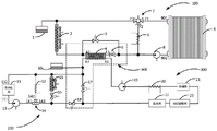
请参阅图1,提供一种燃料电池汽车热管理系统。所述燃料电池汽车热管理系统包括:燃料电池子系统100、动力电池子系统200和热交换控制子系统400。Referring to Figure 1, a fuel cell vehicle thermal management system is provided. The fuel cell vehicle thermal management system includes: a
所述燃料电池子系统100包括:燃料电池本体9、加热器6、第三阀门7、散热器2以及第一阀门3。所述燃料电池子系统100用于实现对燃料电池汽车提供动力。The
所述燃料电池本体9具有燃料电池冷媒入口901和燃料电池冷媒出口902。所述加热器6的输出端与所述燃料电池冷媒入口901通过管路连接。所述加热器6的输入端与所述燃料电池冷媒出口902通过管路连接。所述第三阀门7具有第一端71、第二端72和第三端73。具体的,所述第三阀门7的具体形式可以是电子节温器或三通阀。所述第二端72与所述加热器6的输出端通过管路连接,所述第三端73与所述燃料电池冷媒入口901通过管路连接。所述散热器2的输入端与所述燃料电池冷媒出口902通过管路连接。所述散热器2的输出端与所述第一端71通过管路连接。所述第一阀门3,设置于所述散热器2的输入端与所述燃料电池冷媒出口902之间。The
所述动力电池子系统200包括:动力电池本体11、加热器12、第四阀门14、散热器15以及第五阀门16。所述动力电池子系统200也用于实现对所述燃料电池汽车提供动力。具体的,所述燃料电池汽车由所述燃料电池子系统100来提供动力,或者由所述动力电池子系统200来提供动力需要根据具体的情况进行确定,或者可以由两个子系统共同提供。The
所述动力电池本体11,具有动力电池冷媒入口111和动力电池冷媒出口112。所述加热器12的输入端与所述动力电池冷媒出口112通过管路连接。所述加热器12的输出端与所述动力电池冷媒入口111通过管路连接。所述第四阀门14具有第一端141、第二端142和第三端143。具体的,所述第四阀门14为电子节温器或电子三通阀。所述第二端142与所述加热器12通过管路连接。所述第一端141与所述动力电池冷媒入口111通过管路连接。所述散热器15的输入端与所述动力电池冷媒出口112通过管路连接。所述散热器15的输出端与所述第三端143通过管路连接。所述第五阀门16设置于所述散热器15与所述第三端143之间。The
热交换控制子系统400包括:换热器4、第二阀门5和第七阀门18。The heat
具体的,所述换热器4具有第一入口41、第一出口42、第二入口43和第二出口44。所述第一入口41与所述燃料电池冷媒出口902通过管路连接。所述第一出口42与所述散热器2通过管路连接。所述第二入口43与所述散热器15的输入端通过管路连接。所述第二出口44与所述第三端143通过管路连接。所述第二阀门5设置于所述第一入口41与所述燃料电池冷媒出口902之间。Specifically, the heat exchanger 4 has a
所述燃料电池子系统100与所述动力电池子系统200之间设置所述热交换控制子系统400。所述热交换控制子系统400包括:换热器4、第二阀门5和第七阀门18。当所述第一阀门3关闭,所述第二阀门5导通,所述第七阀门18导通时,可以实现所述燃料电池子系统100与所述动力电池子系统200之间的热交换。本实施例中,所述燃料电池子系统100和所述动力电池子系统200组成的燃料电池汽车,在使用时可以由所述燃料电池本体9和所述燃料电池本体11共同提供车辆所需要的能量,其中在减速、低速、制动回收的时候所述动力电池本体会工作在充电模式回收能量。在常温环境下,燃料电池汽车可以由所述燃料电池子系统100和所述动力电池子系统200共同提供动力,由燃料电池汽车的动力系统或控制系统根据车辆运行需求确定并控制具体由哪个子系统提供动力。The heat
所述燃料电池子系统100和所述动力电池子系统200之间通过热交换控制子系统400实现热交换。所述热交换控制子系统400包括:所述换热器4、所述第二阀门5和所述第七阀门18。在实现热交换的过程中:关闭所述第一阀门3,导通所述第二阀门5,并且导通所述第七阀门18,所述燃料电池子系统100和所述动力电池子系统200之间的热量可以通过所述换热器4实现热交换。Heat exchange is realized between the
请参阅图2,在一个实施例中,所述燃料电池汽车热管理系统还包括:乘客舱供暖子系统300。所述乘客舱供暖子系统300包括:加热器20、除霜器21、司机取暖器23以及散热器22。所述乘客舱供暖子系统300用于给所述燃料电池汽车的车舱内提供热量。Referring to FIG. 2 , in one embodiment, the fuel cell vehicle thermal management system further includes: a passenger
所述加热器20的输入端与所述第二出口44通过管路连接。所述除霜器21的输入端与所述加热器20的输出端通过管路连接。所述司机取暖器23的输入端与所述除霜器21的输出端通过管路连接。所述散热器22的输入端与所述司机取暖器23的输出端通过管路连接,所述散热器22的输出端与所述第二入口43通过管路连接。The input end of the
在一个实施例中,所述乘客舱供暖子系统300可以包括:水泵19、加热器20、除霜器21、多个乘客舱散热器22、司机取暖器23、换热器4。其中,所述多个乘客舱散热器22可以进行并联、串联或者串并联结合等多种方式进行连接。其中,所述乘客舱供暖子系统300和所述动力电池子系统200通过冷却液回路相连接。所述乘客舱供暖子系统300和所述燃料电池子系统100通过换热器4相连接,可以进行热量交换。In one embodiment, the passenger
本实施例中,所述燃料电池汽车热管理系统基于所述燃料电池汽车的电加热液体介质供暖系统、现有单独的动力电池热管理和燃料电池子系统,仅需做少量改装即可实现高效一体化热管理。本实施例保留了直接电加热供暖和电池保温的模式,在燃料电池不工作时仍然可以实现供暖和电池保温的功能。In this embodiment, the fuel cell vehicle thermal management system is based on the electric heating liquid medium heating system of the fuel cell vehicle, the existing separate power battery thermal management and fuel cell subsystems, and only a small amount of modification can be made to achieve high efficiency Integrated thermal management. This embodiment retains the mode of direct electric heating for heating and battery heat preservation, and the functions of heating and battery heat preservation can still be realized when the fuel cell is not working.
请参阅图3,在一个实施例中,所述热交换控制子系统400还包括:第六阀门17。所述第六阀门17设置于所述第二入口43与所述散热器22的输出端之间。Referring to FIG. 3 , in one embodiment, the heat
所述燃料电池子系统100与所述乘客舱供暖子系统300之间设置串联的第二阀门5和换热器4。当所述第二阀门5和所述第六阀门17同时导通时,实现所述燃料电池子系统100与所述乘客舱供暖子系统300之间的热交换。A
所述燃料电池子系统100与所述动力电池子系统200之间通过所述第七阀门18的导通和关闭实现热交换。具体的,当所述第二阀门5、所述第六阀门17和所述第七阀门18同时导通时,可以实现所述燃料电池子系统100、所述动力电池子系统200和所述乘客舱供暖子系统300之间的热交换。而当所述第二阀门5和所述第六阀门17导通,而所述第七阀门18关闭时,只实现所述燃料电池子系统100与所述乘客舱供暖子系统300之间的热交换。Heat exchange is realized between the
本实施例中所述第二阀门5、所述第六阀门17和所述第七阀门18可以是电子阀门。以上的电子阀门方便实现对管路中冷却液的控制。可以理解,所述阀门的具体形式并不做具体的限定,也可以是现有技术中常常采用的其他阀门。设置所述第二阀门5、所述第六阀门17、所述第七阀门18以及换热器4是为了实现所述燃料电池汽车热管理系统中的热交换,避免能源的浪费。In this embodiment, the
本实施例中,所述燃料电池汽车热管理系统包括四个子系统。所述四个子系统分别为所述燃料电池子系统100、所述动力电池子系统200、所述乘客舱供暖子系统300和所述热交换控制子系统400。所述四个子系统能够方便、快捷的实现热交换。所述燃料电池子系统100、所述动力电池子系统200和所述乘客舱供暖子系统300中任意两者之间均可以实现热交换。所述燃料电池汽车热管理系统将所述四个子系统结合在一起,从结构上实现了一体化设计。所述燃料电池汽车热管理系统可以充分利用燃料电池子系统100和动力电池子系统200工作过程中产生的余热。In this embodiment, the fuel cell vehicle thermal management system includes four subsystems. The four subsystems are respectively the
在一个实施例中,所述燃料电池子系统100还包括:水泵8和水箱1。In one embodiment, the
所述水泵8通过管路设置于所述燃料电池冷媒出口902和所述第三端73之间。所述水箱1,通过管路与所述燃料电池冷媒入口901连接。所述水箱1用于提供冷媒,所述冷媒可以是冷却水或者其他的介质。所述水箱1可以和传统的燃料电池汽车的水箱一样,存储一定的冷却水,以实现燃料电池内部的水循环。所述水泵8可以根据控制方法的不同实现冷却水流量的控制。The water pump 8 is disposed between the fuel cell
在一个实施例中,所述燃料电池子系统100具体包括:水箱1、散热器2、第一阀门3、换热器4、第二阀门5、加热器6、第三阀门7、水泵8以及燃料电池本体9。所述第一阀门3和所述第二阀门5可以是任意形式的电磁阀。所述燃料电池子系统100可以实现大循环和小循环两种工作循环。In one embodiment, the
当所述第三阀门7导通所述加热器6的管路时,所述燃料电池子系统100实现小循环工作模式:冷却液经过所述加热器6加热后进入所述燃料电池本体9对电堆进行加热。When the
当所述第一阀门3导通、所述第二阀门5截止并且所述第一端71与所述第三端73导通时,所述燃料电池子系统100实现大循环工作模式。所述燃料电池子系统100在大循环工作模式中,从所述燃料电池本体9中流出的冷却液经所述水泵8、所述第三阀门7、所述第一阀门3达到所述散热器2。所述散热器2控制冷却液和空气的换热量,经过所述散热器2降温后的冷却液返回所述燃料电池本体9中。When the
本实施例中,所述燃料电池子系统100可以实现大循环工作模式或者实现小循环工作模式。同样的可以理解,所述燃料电池子系统100在必要的时候可以实现大小循环同时进行的工作模式。所述燃料电池子系统100可以实现不同的工作模式有利于所述燃料电池汽车热管理系统实现整体的功能。In this embodiment, the
在一个实施例中,所述动力电池子系统200还包括:水泵13和水箱10。In one embodiment, the
所述水泵13通过管路设置于所述动力电池冷媒入口111和所述第一端141之间。所述水箱10,通过管路与所述第二入口43连接。本实施例中的所述水泵13和所述水箱10可以与传统的燃料电池的水泵和水箱一样的设置和功能。The
具体的,所述动力电池子系统200可以包括:水箱10、动力电池本体11、加热器12、水泵13、第四阀门14、散热器15以及第五阀门16。其中,所述第四阀门14为电子节温器或电子三通阀。第五阀门16可以是任意形式的电磁阀。所述动力电池子系统200可以实现大循环和小循环两种循环。Specifically, the
具体的,当所述第四阀门14导通所述加热器12的管路时,所述动力电池子系统200实现小循环工作模式。所述动力电池子系统200在小循环工作模式中冷却液经过所述加热器12加热后经所述水泵13进入所述动力电池本体11对电池包进行加热。Specifically, when the
当所述第五阀门16导通所述第一端141与所述第三端143导通时,所述动力电池子系统200实现大循环工作模式。所述动力电池子系统200在大循环工作模式时:从所述动力电池本体11中流出的冷却液经过所述散热器15进行降温,所述散热器15中控制散热量,冷却液再经过所述第五阀门16、所述第四阀门14,再经过所述水泵13进入所述动力电池本体11中。When the
本实施例中,所述动力电池子系统200可以实现大循环工作模式、小循环工作模式。当然在必要的时候同样可以实现大小循环协同工作的模式。所述动力电池子系统200具有多种工作模式可以提高燃料电池汽车热管理系统的能源利用率。In this embodiment, the
请参阅图4,所述燃料电池汽车热管理系统中,所述乘客舱供暖子系统300可以设置多个所述乘客舱散热器22,所述乘客舱散热器22可以进行并联、串联或者串并联结合等多种方式进行连接。所述乘客舱散热器22可以设置在所述燃料电池汽车的乘客舱中。比如所述乘客舱散热器22可以设置在每一个乘客舱座位的上方、侧方或者下方。所述乘客舱散热器22设置的具体位置不作限定。整体上,所述乘客舱供暖子系统300和所述动力电池子系统200通过冷却液回路相连接。Referring to FIG. 4 , in the fuel cell vehicle thermal management system, the passenger
在一个实施例中,所述燃料电池汽车热管理系统中可以包括不同的工作模式。比如:常温环境所述燃料电池子系统100独立工作、常温环境所述动力电池子系统200独立工作、低温环境所述燃料电池汽车热管理系统的启动控制、低温环境所述燃料电池子系统100中燃料电池的余热给所述乘客舱供暖子系统300中的乘客舱和司机取暖室供暖,以及低温环境所述燃料电池子系统100中燃料电池的余热给所述动力电池子系统200中动力电池保温。In one embodiment, different operating modes may be included in the fuel cell vehicle thermal management system. For example: the
在一个实施例中,提供所述燃料电池子系统100独立工作的原理图。当所述当前环境温度T在正常工作范围内,所述燃料电池子系统100可以独立工作。此时所述第一阀门3导通,所述第二阀门5关闭。冷却水不流经所述换热器4。从所述燃料电池本体9流出的冷却水经过所述水泵8、所述第三阀门7、所述第一阀门3后达到所述散热器2。由所述散热器2中的风扇控制冷却液和空气的换热量,经过所述散热器2降温后的冷却液返回所述燃料电池本体9。通过所述水泵8控制流经所述燃料电池本体9的总流量。通过所述散热器2风扇控制散热量,两者结合控制燃料电池冷却液进出口温度处于合适的范围,保证燃料电池较好的工作条件。In one embodiment, a schematic diagram of the independent operation of the
在一个实施例中,提供所述动力电池子系统200独立工作的原理图。当所述当前环境温度T在正常工作范围内,所述动力电池子系统200可以独立工作。此时所述第六阀门17和所述第七阀门18均关闭,所述第五阀门16导通。从所述动力电池本体11中流出的冷却液经过所述散热器15进行降温。所述散热器15中的风扇通过转速调节控制散热量。经过散热后的冷却液再经过所述第五阀门16、所述第四阀门14以及所述水泵13进入所述动力电池本体11。通过所述水泵13控制流经所述动力电池本体11的总流量。通过所述散热器15风扇控制散热量,两者结合控制动力电池本体冷却液进出口温度处于合适的范围,保证动力电池较好的工作条件。In one embodiment, a schematic diagram of the independent working of the
图5和图6提供了所述燃料电池汽车热管理方法的流程图。具体的,所述燃料电池汽车包括:燃料电池子系统100、动力电池子系统200、乘客舱供暖子系统300和热交换控制子系统400。5 and 6 provide flowcharts of the fuel cell vehicle thermal management method. Specifically, the fuel cell vehicle includes: a
请参阅图5,所述燃料电池汽车热管理方法包括:S100,检测当前环境温度T。这里可以通过燃料电池汽车原有的温度检测装置进行检测,也可以重新设置温度传感器对当前环境温度T进行实时的检测。Referring to FIG. 5 , the fuel cell vehicle thermal management method includes: S100 , detecting the current ambient temperature T. Here, the original temperature detection device of the fuel cell vehicle can be used for detection, or the temperature sensor can be reset to detect the current ambient temperature T in real time.
S200,当所述当前环境温度T≥所述动力电池子系统200中动力电池需要保温和所述乘客舱供暖子系统300需要供暖的环境温度阈值T1时,所述燃料电池汽车进入正常环境启动模式,否则,所述燃料电池汽车进入低温环境启动模式。S200, when the current ambient temperature T ≥ the ambient temperature threshold T1 at which the power battery needs to be kept warm and the passenger
本实施例中,所述燃料电池汽车热管理方法可以先检测当前环境温度,通过不同的环境温度确定需要设置所述燃料电池汽车处于的工作模式。当所述当前环境温度T较低时,设置所述燃料电池汽车进入冷启动模式。当所述当前环境温度T≥所述动力电池子系统200中动力电池需要保温和所述乘客舱供暖子系统300需要供暖的环境温度阈值T1时,所述燃料电池汽车进入正常启动模式。否则,所述燃料电池汽车进入低温环境启动模式。具体的,所述燃料电池汽车控制机制可以通过检测装置和计算机控制系统来实现。本实施例中,合理的设置所述燃料电池的工作状态有利于实现稳定可靠的热管理,减少热能的浪费。同时解决了燃料电池快速启动的问题和动力电池保温的问题。In this embodiment, the fuel cell vehicle thermal management method may first detect the current ambient temperature, and determine the working mode that the fuel cell vehicle needs to be set to according to different ambient temperatures. When the current ambient temperature T is low, the fuel cell vehicle is set to enter a cold start mode. When the current ambient temperature T ≥ the ambient temperature threshold T1 at which the power battery in the
请参阅图6,在一个实施例中,所述低温环境启动模式包括以下步骤:Referring to FIG. 6, in one embodiment, the low temperature environment startup mode includes the following steps:
S201,当所述当前环境温度T>所述燃料电池子系统100中燃料电池最低自启动温度T2时,所述燃料电池汽车进入第二步骤。当所述当前环境温度T≤所述燃料电池子系统100中燃料电池最低自启动温度T2时,所述燃料电池汽车进入第一步骤,直至所述当前环境温度T>所述燃料电池子系统100中燃料电池最低自启动温度T2时,所述燃料电池汽车再进入第二步骤。S201 , when the current ambient temperature T > the lowest self-starting temperature T2 of the fuel cell in the
请参阅图7,所述第一步骤为控制所述燃料电池子系统100实现小循环工作模式,控制所述动力电池子系统200实现小循环工作模式,所述燃料电池子系统100和所述动力电池子系统200中使用的电能由所述动力电池子系统200中的动力电池提供。Referring to FIG. 7 , the first step is to control the
在所述第一步骤时环境温度较低,所述燃料电池子系统100无法实现自启动。如图7所示,所述动力电池子系统200采用小循环工作模式,所述第五阀门16、所述第六阀门17和所述第七阀门18均关闭。所述第四阀门14仅导通所述加热器12的回路,此时冷却液经过所述加热器12加热后经所述水泵13进入所述动力电池本体11对动力电池进行加热。所述燃料电池子系统100采用小循环工作模式,所述第三阀门7仅导通所述加热器6回路。冷却液经过所述加热器6加热后进入所述燃料电池本体9对电堆进行加热。此时所述动力电池子系统200中的加热器12和所述燃料电池子系统100中的加热器6的电能来自动力电池。During the first step, the ambient temperature is low, and the
请参阅图8提供了所述第二步骤的工作原理图。所述第二步骤为控制所述燃料电池子系统100实现小循环工作模式,控制所述动力电池子系统200实现小循环工作模式,所述燃料电池子系统100和所述动力电池子系统200中使用的电能由所述燃料电池子系统100中的燃料电池和所述动力电池子系统200中的动力电池共同提供。Please refer to FIG. 8 for a working schematic diagram of the second step. The second step is to control the
图8中,所述动力电池子系统200采用小循环工作模式,所述第五阀门16、所述第六阀门17和所述第七阀门18均关闭。所述第四阀门14仅导通所述加热器12的回路。此时冷却液经过所述加热器12加热后经所述水泵13进入所述动力电池本体11对动力电池进行加热。所述燃料电池子系统100采用小循环工作模式,所述第三阀门仅导通所述加热器6回路,冷却液经过所述加热器6加热后进入所述燃料电池本体9对电堆进行加热。此时所述燃料电池子系统100启动并工作在低温启动模式,利用自身产热加快温度上升。所述动力电池子系统200中所述加热器12和所述燃料电池子系统100中的所述加热器6的电能来自燃料电池和动力电池,如果车辆运行有功率需求,燃料电池和动力电池输出能力足够情况下可以提供电能驱动车辆。In FIG. 8 , the
请再次参阅图6,在一个实施例中,所述低温环境启动模式还包括以下步骤:Referring to FIG. 6 again, in one embodiment, the low-temperature environment startup mode further includes the following steps:
S202,检测燃料电池小循环冷却液温度。S202 , the temperature of the small circulating cooling liquid of the fuel cell is detected.
S203,当所述燃料电池小循环冷却液温度达到燃料电池工作温度T3时,所述燃料电池汽车进入第三步骤。S203, when the temperature of the fuel cell small circulating coolant reaches the fuel cell operating temperature T3, the fuel cell vehicle enters the third step.
请参阅图9,提供了所述第三步骤的工作原理图。所述第三步骤为:控制所述动力电池子系统200实现小循环工作模式,控制所述燃料电池子系统100实现大小循环协作工作模式,所述燃料电池子系统100和所述动力电池子系统200中使用的电能由所述燃料电池子系统100中的燃料电池和所述动力电池子系统200中的动力电池共同提供。Referring to Figure 9, a schematic diagram of the operation of the third step is provided. The third step is: controlling the
如图9所示,控制所述动力电池子系统200采用小循环工作模式,所述第五阀门16、所述第六阀门17和所述第七阀门18均关闭。所述第四阀门14仅导通所述加热器12的回路,此时冷却液经过加热器12后经所述水泵13进入所述动力电池本体11,此时调节所述加热器12和所述水泵13流量控制动力电池温度处于合适范围。所述燃料电池子系统100采用大小循环协作模式,所述第一阀门3导通,所述第二阀门5关闭。由所述第三阀门7调节所述加热器6回路和所述散热器2回路的流量比例,调节进入所述燃料电池本体9的温度在合适范围。流出所述燃料电池本体9的冷却液经过所述水泵8之后一部分流经小循环回路,一部分流经所述第一阀门3、所述散热器2进行降温,两部分混合后进入所述燃料电池本体9进行电堆冷却。在所述第三步骤中大循环中的冷却水温度逐渐升高。所述动力电池子系统200中所述加热器12消耗的电能来自燃料电池和动力电池。如果车辆运行有功率需求,燃料电池和动力电池可以提供电能驱动车辆。As shown in FIG. 9 , the
具体的,所述动力电池子系统200中:实时检测所述动力电池本体11的温度,计算出所述动力电池冷媒入口111的冷却水流量和温度。通过所述水泵13控制进入所述动力电池冷媒入口111总流量。通过所述第四阀门14控制流经所述加热器12、所述散热器15和所述第五阀门16的流量比例,控制所述散热器15风扇转速,两者结合调节进入所述动力电池冷媒入口111的水温。Specifically, in the
请再次参阅图6,在一个实施例中,所述低温环境启动模式还包括以下步骤:Referring to FIG. 6 again, in one embodiment, the low-temperature environment startup mode further includes the following steps:
S204,检测燃料电池大循环冷却液温度。S204, the temperature of the large circulating cooling liquid of the fuel cell is detected.
S205,当所述燃料电池大循环冷却液温度达到低温环境工作阈值T4时,所述燃料电池汽车进入第四步骤。S205 , when the temperature of the fuel cell large circulating coolant reaches the low temperature environment operating threshold T4, the fuel cell vehicle enters the fourth step.
请参阅图10,提供所述第四步骤的工作原理图。所述第四步骤为控制所述动力电池子系统200实现小循环工作模式,控制所述燃料电池子系统100实现大小循环协作工作模式,所述热交换控制子系统400控制所述燃料电池子系统100与所述乘客舱供暖子系统300进行换热,所述乘客舱供暖子系统300中的冷却液温度逐渐上升,所述燃料电池子系统100和所述动力电池子系统200中使用的电能由所述燃料电池子系统100中的燃料电池和所述动力电池子系统200中的动力电池共同提供。Referring to FIG. 10, a working schematic diagram of the fourth step is provided. The fourth step is to control the
具体的,当所述燃料电池子系统大循环冷却液温度达到一定阈值之后,所述燃料电池汽车热管理系统的工作原理如图10所示。所述动力电池子系统200采用小循环工作模式,所述第五阀门16、所述第六阀门17和所述第七阀门18均关闭,所述第四阀门14仅导通所述加热器12的回路。此时冷却液经过所述加热器12后经所述水泵13进入所述动力电池本体11,此时调节所述加热器12和所述水泵13流量控制动力电池温度处于合适范围。所述燃料电池子系统100采用大小循环协作模式,所述第一阀门3关闭,第二阀门5导通,由所述第三阀门7调节所述加热器6回路和所述散热器2回路的流量比例,调节进入所述燃料电池本体9的温度在合适范围。流出所述燃料电池本体9的冷却液经过所述水泵8后一部分流经小循环回路,一部分流经所述第二阀门5、所述换热器4。在所述换热器4中与所述乘客舱供暖子系统300的冷却液进行换热,再经过所述散热器2进行散热降温。两部分混合后进入所述燃料电池本体9进行电堆冷却。所述乘客舱供暖子系统300中的冷却液温度逐渐上升。所述动力电池子系统200中所述加热器6消耗的电能来自燃料电池和动力电池,如果车辆运行有功率需求,燃料电池和动力电池可以提供电能驱动车辆。Specifically, when the temperature of the large circulating coolant of the fuel cell subsystem reaches a certain threshold, the working principle of the thermal management system of the fuel cell vehicle is shown in FIG. 10 . The
请再次参阅图5,在一个实施例中,所述燃料电池汽车热管理方法还包括:Referring to FIG. 5 again, in one embodiment, the fuel cell vehicle thermal management method further includes:
S300,检测乘客舱供暖系统供暖介质温度。S300, the temperature of the heating medium of the passenger compartment heating system is detected.
S301,当乘客舱供暖系统供暖介质温度达到动力电池保温温度阈值T5时,所述燃料电池汽车由低温环境启动模式进入到低温环境工作模式。S301 , when the temperature of the heating medium of the passenger compartment heating system reaches the power battery insulation temperature threshold T5, the fuel cell vehicle enters the low temperature environment working mode from the low temperature environment startup mode.
所述低温环境工作模式为控制所述动力电池子系统200实现大循环工作模式。控制所述燃料电池子系统100实现大小循环协作工作模式。所述热交换控制子系统400控制所述燃料电池子系统100分别与所述动力电池子系统200和所述乘客舱供暖子系统300进行换热。所述动力电池子系统200中的动力电池保温,所述乘客舱供暖子系统300中的冷却液温度逐渐上升。所述燃料电池子系统100和所述动力电池子系统200中使用的电能由所述燃料电池子系统100中的燃料电池和所述动力电池子系统200中的动力电池共同提供。The low-temperature environment working mode is to control the
请参阅图11,提供了所述燃料电池汽车热管理方法中的一个工作状态的工作原理图。检测乘客舱供暖子系统300中冷却液温度。当乘客舱供暖系统供暖介质温度达到动力电池保温温度阈值T5时,所述燃料电池汽车由低温环境启动模式进入到低温环境工作模式。所述燃料电池子系统100、所述动力电池子系统200和所述乘客舱供暖子系统300联合工作。所述燃料电池子系统100采用大小循环协作模式,所述第一阀门3关闭,所述第二阀门5导通,由所述第三阀门7调节所述加热器6回路和所述散热器2回路的流量比例,调节进入所述燃料电池本体9的温度在合适范围。流出所述燃料电池本体9的冷却液经过水泵后一部分流经小循环回路,一部分流经所述第二阀门5、所述换热器4。在所述换热器4中与所述乘客舱供暖子系统300的冷却液进行换热,再经过所述散热器2进行散热降温。两部分混合后进入所述燃料电池本体9进行电堆冷却。所述动力电池子系统200和所述乘客舱供暖子系统300形成一个回路,此时所述第六阀门17关闭,所述第七阀门18导通,所述第五阀门16关闭,第三阀门(电子节温器或三通阀)7关闭所述加热器6回路。冷却液再经过换热器4之后被加热到一定温度,再经过所述水泵19、所述加热器20,首先经过所述除霜器21提供除霜需要的热量,再经过所述司机加热器23和所述乘客舱散热器22,对乘客舱进行供暖。然后冷却液再通过所述第七阀门18、所述第四阀门(电子节温器或三通阀)14、所述水泵13,进入所述动力电池本体11对电池进行保温,最后冷却液返回所述换热器4再进行换热升温。其中所述加热器20可以在燃料电池余热不足以满足整车供暖和动力电池保温需求时提供额外加热,保证乘客舱供暖和动力电池保温的效果。Please refer to FIG. 11 , which provides a working principle diagram of one working state of the fuel cell vehicle thermal management method. The coolant temperature in the passenger
在一个实施例中,请再次参阅图5,所述燃料电池汽车热管理方法还包括:In one embodiment, please refer to FIG. 5 again, the fuel cell vehicle thermal management method further includes:
S400,检测燃料电池冷却液温度。S400, the temperature of the fuel cell coolant is detected.
S401,当燃料电池冷却液温度达到燃料电池工作温度T6时,所述燃料电池汽车由常温环境启动模式进入到常温环境工作模式。S401, when the fuel cell coolant temperature reaches the fuel cell operating temperature T6, the fuel cell vehicle enters a normal temperature environment operating mode from a normal temperature environment startup mode.
所述常温环境工作模式为控制所述动力电池子系统200实现大循环工作模式,控制所述燃料电池子系统100实现大小循环协作工作模式,所述燃料电池子系统100和所述动力电池子系统200分别进行换热和散热,所述燃料电池子系统100和所述动力电池子系统200中使用的电能由所述燃料电池子系统100中的燃料电池和所述动力电池子系统200中的动力电池共同提供。The normal temperature environment working mode is to control the
在一个实施例中,正常环境启动模式包括:控制所述第一阀门3导通,所述第二阀门5关闭,所述第六阀门17关闭,所述第七阀门18关闭,所述燃料电池子系统100和所述动力电池子系统200分别独立工作。所述正常环境启动模式是根据当前环境温度进行选择和设置的。所述正常环境启动模式中电加热器无需启动。水泵等需要消耗电能的。具体的,所述动力电池子系统200中,监测所述动力电池11的温度,计算出需要进入所述动力电池冷媒入口111的冷却水流量和温度。通过所述水泵13控制总流量。通过所述第四阀门14控制流经所述加热器12、所述散热器15和所述第五阀门16的流量比例。控制所述散热器15的风扇转速,两种方案结合调节进入所述动力电池冷媒入口111的水温。所述燃料电池子系统100中,监测所述燃料电池本体9的温度和发热功率,通过所述水泵8控制流量,通过所述第三阀门7和所述散热器2控制所述燃料电池冷媒入口901的水温。In one embodiment, the normal environment startup mode includes: controlling the
本申请提供了燃料电池汽车热管理系统。所述燃料电池汽车热管理系统包括:燃料电池子系统100、动力电池子系统200和乘客舱供暖子系统300。所述燃料电池子系统100、所述动力电池子系统200和所述乘客舱热管理系统30通过换热器和冷却液回路连接为一个整体。在不同条件下可以实现独立工作和协同工作。所述燃料电池子系统100中燃料电池采用水冷方式控制燃料电池工作在合适温度,利用燃料电池工作时产生热量以及辅助加热器产生的热量,通过冷却液回路对所述动力电池子系统200中的动力电池和所述乘客舱供暖子系统300中的乘客舱进行供暖,保证了冬季寒冷环境中乘客舱保暖满足需求,保持动力电池温度在合理,实现整车能耗的改善。The present application provides a fuel cell vehicle thermal management system. The fuel cell vehicle thermal management system includes: a
本申请提出的所述燃料电池汽车热管理系统可以控制燃料电池工作在合适温度,有利于提高性能和延长寿命。本申请提出的所述燃料电池汽车热管理系统充分利用了燃料电池余热用于乘客舱供暖和电池保温,系统效率明显提高,提高了车辆在冬季的续驶里程。本申请提出的所述燃料电池汽车热管理系统可以实现低温环境动力电池和燃料电池协同工作快速升温启动。The fuel cell vehicle thermal management system proposed in the present application can control the fuel cell to work at a suitable temperature, which is beneficial to improve performance and prolong life. The fuel cell vehicle thermal management system proposed in the present application makes full use of the fuel cell waste heat for passenger compartment heating and battery insulation, the system efficiency is significantly improved, and the cruising range of the vehicle in winter is improved. The fuel cell vehicle thermal management system proposed in the present application can realize a low temperature environment power battery and a fuel cell working together to quickly warm up and start.
本申请提出了一种燃料电池汽车热管理系统。所述燃料电池汽车热管理系统可以利用所述燃料电池子系统100的余热给乘客舱供暖,以及对所述动力电池子系统200进行保温。所述燃料电池汽车热管理系统提供了燃料电池汽车中燃料电池子系统100、动力电池子系统200和整车的高效一体化热管理。所述燃料电池汽车热管理系统的具体实施方式在上述应用实例中进行了具体描述,但不局限于上述的具体实施方式以上所述实施例的各技术特征可以进行任意的组合,为使描述简洁,未对上述实施例中的各个技术特征所有可能的组合都进行描述,然而,只要这些技术特征的组合不存在矛盾,都应当认为是本说明书记载的范围。The present application proposes a thermal management system for a fuel cell vehicle. The fuel cell vehicle thermal management system can utilize the waste heat of the
以上所述实施例仅表达了本申请的几种实施方式,其描述较为具体和详细,但并不能因此而理解为对申请专利范围的限制。应当指出的是,对于本领域的普通技术人员来说,在不脱离本申请构思的前提下,还可以做出若干变形和改进,这些都属于本申请的保护范围。因此,本申请专利的保护范围应以所附权利要求为准。The above-mentioned embodiments only represent several embodiments of the present application, and the descriptions thereof are relatively specific and detailed, but should not be construed as a limitation on the scope of the patent application. It should be pointed out that for those skilled in the art, without departing from the concept of the present application, several modifications and improvements can be made, which all belong to the protection scope of the present application. Therefore, the scope of protection of the patent of the present application shall be subject to the appended claims.
Claims (9)
Priority Applications (1)
| Application Number | Priority Date | Filing Date | Title |
|---|---|---|---|
| CN201810393606.4A CN109980246B (en) | 2018-04-27 | 2018-04-27 | Fuel cell vehicle thermal management system |
Applications Claiming Priority (1)
| Application Number | Priority Date | Filing Date | Title |
|---|---|---|---|
| CN201810393606.4A CN109980246B (en) | 2018-04-27 | 2018-04-27 | Fuel cell vehicle thermal management system |
Publications (2)
| Publication Number | Publication Date |
|---|---|
| CN109980246A CN109980246A (en) | 2019-07-05 |
| CN109980246B true CN109980246B (en) | 2020-01-21 |
Family
ID=67075929
Family Applications (1)
| Application Number | Title | Priority Date | Filing Date |
|---|---|---|---|
| CN201810393606.4A Active CN109980246B (en) | 2018-04-27 | 2018-04-27 | Fuel cell vehicle thermal management system |
Country Status (1)
| Country | Link |
|---|---|
| CN (1) | CN109980246B (en) |
Cited By (1)
| Publication number | Priority date | Publication date | Assignee | Title |
|---|---|---|---|---|
| DE102021120744A1 (en) | 2021-08-10 | 2023-02-16 | Man Truck & Bus Se | Vehicle with coupled cooling circuits for cooling an electrochemical cell |
Families Citing this family (17)
| Publication number | Priority date | Publication date | Assignee | Title |
|---|---|---|---|---|
| DK180361B1 (en) * | 2019-10-17 | 2021-02-04 | Blue World Technologies Holding ApS | Fuel cell system with a multi-stream heat exchanger, its use and method of its operation |
| CN112952139B (en) * | 2019-12-10 | 2022-08-19 | 中车时代电动汽车股份有限公司 | Fuel cell heat dissipation system |
| CN110993987B (en) * | 2019-12-20 | 2021-01-12 | 东风汽车集团有限公司 | Fuel cell vehicle cooling system and control method thereof |
| CN111152689A (en) * | 2019-12-26 | 2020-05-15 | 北汽福田汽车股份有限公司 | Vehicle control system, method and vehicle |
| CN111361455B (en) * | 2020-03-23 | 2021-10-26 | 中铁轨道交通装备有限公司 | Hydrogen powered vehicle |
| CN111619306B (en) * | 2020-04-21 | 2021-05-14 | 清华大学 | Energy Comprehensive Utilization System |
| CN113725458A (en) * | 2020-05-25 | 2021-11-30 | 北京亿华通科技股份有限公司 | Thermal management control method and system and fuel cell vehicle |
| CN111725536A (en) * | 2020-06-30 | 2020-09-29 | 上海捷氢科技有限公司 | System and method for rapid pre-cooling and auxiliary heating of fuel cell |
| CN112002925A (en) * | 2020-07-14 | 2020-11-27 | 清华大学 | Fuel cell automobile management system and control method thereof |
| CN114435076B (en) * | 2020-10-30 | 2024-05-28 | 北京亿华通科技股份有限公司 | A control method for a fuel cell waste heat utilization system |
| CN112599815B (en) * | 2020-12-14 | 2022-04-15 | 清华大学 | Cold energy utilization device and cold energy utilization system |
| CN112582639B (en) * | 2020-12-20 | 2024-07-23 | 武汉格罗夫氢能汽车有限公司 | A thermal management heat exchange system and control method for a fuel cell hydrogen energy vehicle |
| CN113246801B (en) * | 2021-05-12 | 2022-05-03 | 中国第一汽车股份有限公司 | A vehicle thermal management system for a fuel cell vehicle |
| CN113733855B (en) * | 2021-10-26 | 2023-12-22 | 厦门金龙联合汽车工业有限公司 | A low-temperature quick start system and control method for electric vehicles |
| CN113910866B (en) * | 2021-10-26 | 2024-01-30 | 厦门金龙联合汽车工业有限公司 | Low-temperature reserved starting system and control method for electric automobile battery |
| CN114132224B (en) * | 2021-12-30 | 2025-08-05 | 海南海马汽车有限公司 | Thermal Management Systems and Automobiles |
| CN115275444B (en) * | 2022-09-30 | 2023-01-10 | 中国第一汽车股份有限公司 | Method and device for adjusting battery temperature of vehicle and vehicle |
Citations (2)
| Publication number | Priority date | Publication date | Assignee | Title |
|---|---|---|---|---|
| CN106848350A (en) * | 2015-12-07 | 2017-06-13 | 北京亿华通科技股份有限公司 | The fuel cell cogeneration system and motor vehicle driven by mixed power of motor vehicle driven by mixed power |
| CN106945537A (en) * | 2017-01-23 | 2017-07-14 | 清华大学 | Fuel cell car heat management system |
-
2018
- 2018-04-27 CN CN201810393606.4A patent/CN109980246B/en active Active
Patent Citations (2)
| Publication number | Priority date | Publication date | Assignee | Title |
|---|---|---|---|---|
| CN106848350A (en) * | 2015-12-07 | 2017-06-13 | 北京亿华通科技股份有限公司 | The fuel cell cogeneration system and motor vehicle driven by mixed power of motor vehicle driven by mixed power |
| CN106945537A (en) * | 2017-01-23 | 2017-07-14 | 清华大学 | Fuel cell car heat management system |
Cited By (1)
| Publication number | Priority date | Publication date | Assignee | Title |
|---|---|---|---|---|
| DE102021120744A1 (en) | 2021-08-10 | 2023-02-16 | Man Truck & Bus Se | Vehicle with coupled cooling circuits for cooling an electrochemical cell |
Also Published As
| Publication number | Publication date |
|---|---|
| CN109980246A (en) | 2019-07-05 |
Similar Documents
| Publication | Publication Date | Title |
|---|---|---|
| CN109980246B (en) | Fuel cell vehicle thermal management system | |
| CN109962268A (en) | Fuel cell car thermal management algorithm | |
| US11545677B2 (en) | Fuel cell vehicle thermal management system with cold start function and control method thereof | |
| CN111029616B (en) | Port transport vehicle fuel cell thermal management system considering service life of galvanic pile | |
| CN113547890B (en) | Thermal management system, thermal management system control method and automobile | |
| CN106004338B (en) | Automotive Thermal Management System and Automotive | |
| CN101000972B (en) | Thermal control device for battery of mixed power vehicle | |
| CN114335595A (en) | A fuel cell vehicle thermal management system and its control method | |
| CN108281735B (en) | An electric vehicle battery thermal insulation system and method thereof | |
| CN107994290B (en) | A composite thermal management system for electric vehicle batteries | |
| WO2018113750A1 (en) | Fuel cell system and fuel cell vehicle | |
| CN109795312B (en) | Whole vehicle thermal management system of plug-in hybrid electric vehicle | |
| WO2013139104A1 (en) | Thermal management system for fuel cell, and fuel cell system and vehicle having same | |
| CN107839433A (en) | The thermal management system of whole of plug-in hybrid-power automobile | |
| CN103660916A (en) | Heat control system for hybrid power or range-extending type electric automobile | |
| CN108232238B (en) | A fuel cell system, control method and fuel cell vehicle | |
| CN112428766B (en) | Hybrid vehicle heat management system and management method | |
| CN112635788B (en) | Thermal management system and thermal management method for fuel cell vehicle | |
| CN110767957A (en) | Composite heating system and heating method of hybrid powertrain power battery | |
| CN208336386U (en) | A kind of heat treatment system for fuel cell pack | |
| CN115610184A (en) | Thermal management system for commercial heavy truck with hydrogen hybrid power | |
| CN204243158U (en) | A liquid-cooled battery system for new energy vehicles | |
| CN115107502B (en) | Hybrid electric vehicle thermal management system and method based on thermoelectric and phase-change materials | |
| CN210634381U (en) | A composite heating system for a hybrid powertrain power battery | |
| CN116722268A (en) | A vehicle and its power battery temperature management method and system |
Legal Events
| Date | Code | Title | Description |
|---|---|---|---|
| PB01 | Publication | ||
| PB01 | Publication | ||
| SE01 | Entry into force of request for substantive examination | ||
| SE01 | Entry into force of request for substantive examination | ||
| GR01 | Patent grant | ||
| GR01 | Patent grant | ||
| TR01 | Transfer of patent right |
Effective date of registration: 20221221 Address after: No. 160, Floor 2, Building 2, Yard 9, Fengyuan Street, Daxing District, Beijing 102600 Patentee after: Beijing Yikong Hydrogen Energy Technology Co.,Ltd. Address before: 100084 No. 1 Tsinghua Yuan, Beijing, Haidian District Patentee before: TSINGHUA University |
|
| TR01 | Transfer of patent right |