CN109898866B - Two-end tensioning structure with bonded post-tensioning prestressed beam for sectional construction - Google Patents
Two-end tensioning structure with bonded post-tensioning prestressed beam for sectional construction Download PDFInfo
- Publication number
- CN109898866B CN109898866B CN201910210846.0A CN201910210846A CN109898866B CN 109898866 B CN109898866 B CN 109898866B CN 201910210846 A CN201910210846 A CN 201910210846A CN 109898866 B CN109898866 B CN 109898866B
- Authority
- CN
- China
- Prior art keywords
- plate
- mounting
- fixedly provided
- installation
- mounting plate
- Prior art date
- Legal status (The legal status is an assumption and is not a legal conclusion. Google has not performed a legal analysis and makes no representation as to the accuracy of the status listed.)
- Active
Links
- 238000010276 construction Methods 0.000 title claims abstract description 17
- 238000009434 installation Methods 0.000 claims abstract description 43
- 210000001503 joint Anatomy 0.000 claims abstract description 10
- 230000003014 reinforcing effect Effects 0.000 claims description 16
- 239000004567 concrete Substances 0.000 claims description 9
- 238000001125 extrusion Methods 0.000 claims description 8
- 238000003032 molecular docking Methods 0.000 claims description 5
- 230000011218 segmentation Effects 0.000 claims 1
- 238000003466 welding Methods 0.000 description 5
- 229910001294 Reinforcing steel Inorganic materials 0.000 description 4
- 238000004873 anchoring Methods 0.000 description 3
- 210000003205 muscle Anatomy 0.000 description 3
- 238000005516 engineering process Methods 0.000 description 2
- FGRBYDKOBBBPOI-UHFFFAOYSA-N 10,10-dioxo-2-[4-(N-phenylanilino)phenyl]thioxanthen-9-one Chemical compound O=C1c2ccccc2S(=O)(=O)c2ccc(cc12)-c1ccc(cc1)N(c1ccccc1)c1ccccc1 FGRBYDKOBBBPOI-UHFFFAOYSA-N 0.000 description 1
- 229910000831 Steel Inorganic materials 0.000 description 1
- 230000009286 beneficial effect Effects 0.000 description 1
- 238000009435 building construction Methods 0.000 description 1
- 230000008878 coupling Effects 0.000 description 1
- 238000010168 coupling process Methods 0.000 description 1
- 238000005859 coupling reaction Methods 0.000 description 1
- 238000010586 diagram Methods 0.000 description 1
- 238000000034 method Methods 0.000 description 1
- 239000011513 prestressed concrete Substances 0.000 description 1
- 238000007711 solidification Methods 0.000 description 1
- 230000008023 solidification Effects 0.000 description 1
- 239000010959 steel Substances 0.000 description 1
Images



Landscapes
- Joining Of Building Structures In Genera (AREA)
- Bridges Or Land Bridges (AREA)
Abstract
The invention discloses a tensioning structure for two ends of a bonded post-tensioning prestressed beam in sectional construction, which comprises an anchor plate and an installation cavity, wherein a threaded sleeve is fixedly installed on one side of the anchor plate through a bolt column, a fixed plate is fixedly installed on the threaded sleeve through a second threaded butt joint sleeve, an installation frame is fixedly installed on one side of the fixed plate, a first installation plate is fixedly installed on the installation frame through a threaded column, an installation backing plate is fixedly installed on the other side of the anchor plate, a spiral rib is fixedly installed on one side of the installation backing plate through a butt joint seat, and the end part of the spiral rib is fixedly installed with the installation cavity through a second installation seat. The tensioning device is provided with the mounting frame and the threaded column to realize tensioning fine adjustment, so that the situation that pulling and loosening are required again after engineering construction is finished is avoided or reduced, the arranged reset spring can realize the function of tensioning two ends through self reset performance, and the tensioning device is worthy of popularization and use.
Description
Technical Field
The invention relates to the technical field of building construction, in particular to a tensioning structure for two ends of a bonded post-tensioning prestressed beam in sectional construction.
Background
At present, along with the diversification of building forms, the building is required to have large space and large span, higher requirements are provided for the structure, the prestressed beam is widely applied to a large-span concrete structure, meanwhile, along with the increase of more and more track construction projects, the sectional installation and pouring of the prestressed beam caused by pit-dividing construction are provided, the improvement is provided for the construction of the bonded post-tensioned prestressed beam aiming at the condition, the anchoring section of the bonded post-tensioned prestressed concrete beam with the length of the conventional prestressed bar not exceeding 20m adopts the form, the extrusion anchor and the backing plate of the anchoring section are directly poured in the concrete of the beam column node, aiming at the prestressed beam of the sectional construction, because one side beam of the tensioning end is not installed, the prestressed bar at one side of the tensioning end belongs to a free state, the stress of the spiral bar is not uniform in the concrete pouring process by adopting the conventional anchoring form, and therefore, the improvement on the existing technology is necessary, to solve the above problems.
Disclosure of Invention
The invention aims to provide a tension structure for two ends of a bonded post-tension prestressed beam in sectional construction, so as to solve the problems in the background technology.
In order to achieve the purpose, the invention provides the following technical scheme: a stretching structure with two ends stretching prestressed beams after bonding for segmental construction comprises an anchor plate and an installation cavity, wherein one side of the anchor plate is fixedly provided with a thread bush through a bolt column, the thread bush is fixedly provided with a fixed plate through a second thread butt joint bush, one side of the fixed plate is fixedly provided with an installation frame, the installation frame is fixedly provided with a first installation plate through a thread column, the other side of the anchor plate is fixedly provided with an installation backing plate, one side of the installation backing plate is fixedly provided with a spiral rib through a butt joint seat, the end part of the spiral rib is fixedly provided with an installation cavity through a second installation seat, the installation cavity is fixedly provided with a second installation plate through a limiting cylinder body, a reset spring is fixedly arranged between the butt joint seat outside the limiting cylinder body and the second installation plate, three groups of reinforcing bars extending out of the second installation plate are fixedly arranged, and the end part of the reinforcing bar is fixedly provided with an extrusion anchor through a finished product base plate, a reinforcing bar beam is sleeved on the reinforcing bar outside the second mounting plate, and a reinforcing rib is fixedly arranged on the reinforcing bar beam.
Preferably, the finished backing plate and the extrusion anchor are wrapped with concrete modules.
Preferably, two sets of sliding grooves are formed in the limiting cylinder body and fixedly connected with the mounting cavity through sliding blocks.
Preferably, the outer side wall of the first mounting plate is fixedly provided with a first rubber pad, and the first mounting plate is fixedly provided with a first fastening bolt matched with the first mounting plate for use.
Preferably, a second rubber pad is fixedly mounted on the outer side wall of the second mounting plate, and a second fastening bolt matched with the second mounting plate is fixedly mounted on the second mounting plate.
Preferably, the first mounting plate is fixedly connected with the threaded column through a first thread butting sleeve, and an adjusting bolt is fixedly mounted on the threaded column.
Preferably, the fixing plate is fixedly connected with the second thread butting sleeve through a fixing column.
Preferably, the installation base plate and the butt joint seat are fixedly installed through an installation sleeve, and a screw is fixedly installed on the installation sleeve.
Compared with the prior art, the invention has the beneficial effects that: compared with the traditional stretching prestressed beam stretching structure, the stretching structure with the two ends of the stretching prestressed beam after bonding in the segmented construction is provided with the mounting frame and the threaded columns to realize the stretching fine adjustment function, thereby avoiding or reducing the situation that the stretching and loosening are required to be carried out again after the engineering construction is finished, reducing the inconvenience of workers during the operation, improving the practicability of the stretching structure, not only protecting the devices on the stretching structure, but also improving the stability of the stretching structure during the stretching, avoiding the shaking situation during the operation, achieving good limiting function, improving the overall strength by the arranged spiral ribs, being better suitable for different operation environments, ensuring the operation quality, simultaneously improving the firmness with the installation parts and ensuring the self-resetting performance of the arranged reset spring, the function of stretching the two ends is realized, so that the working personnel can better work, the stability during stretching is ensured, the application range is expanded, and the device is worthy of popularization and application.
Drawings
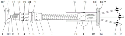
FIG. 1 is a first internal schematic view of the present invention;
FIG. 2 is a second internal schematic view of the present invention;
FIG. 3 is a schematic view of the overall structure of the present invention;
FIG. 4 is a first partial schematic of the present invention;
fig. 5 is a second partial structural diagram of the present invention.
In the figure: 1. a first mounting plate; 101. a first fastening bolt; 102. a first rubber pad; 2. adjusting the bolt; 3. a threaded post; 4. fixing a column; 5. a threaded sleeve; 6. an anchor plate; 7. installing a sleeve; 8. a docking station; 9. a spiral rib; 10. a second mounting seat; 11. installing a cavity; 12. reinforcing bars; 13. a second mounting plate; 1301. a second rubber pad; 1302. a second fastening bolt; 14. a finished base plate; 15. extruding the anchor; 16. a first threaded docking sleeve; 17. a mounting frame; 18. a fixing plate; 19. a second thread coupling sleeve; 20. a bolt column; 21. installing a base plate; 22. a slider; 23. a limiting cylinder body; 2301. a chute; 24. a return spring; 25. a steel bar beam; 26. reinforcing ribs; 27. a concrete module.
Detailed Description
The technical solutions in the embodiments of the present invention will be clearly and completely described below with reference to the drawings in the embodiments of the present invention, and it is obvious that the described embodiments are only a part of the embodiments of the present invention, and not all of the embodiments. All other embodiments, which can be derived by a person skilled in the art from the embodiments given herein without making any creative effort, shall fall within the protection scope of the present invention.
In the description of the present invention, it should be noted that the terms "upper", "lower", "inner", "outer", "front", "rear", "both ends", "one end", "the other end", and the like indicate orientations or positional relationships based on those shown in the drawings, and are only for convenience of description and simplicity of description, but do not indicate or imply that the referred device or element must have a specific orientation, be constructed in a specific orientation, and be operated, and thus, should not be construed as limiting the present invention. Furthermore, the terms "first" and "second" are used for descriptive purposes only and are not to be construed as indicating or implying relative importance.
In the description of the present invention, it is to be noted that, unless otherwise explicitly specified or limited, the terms "mounted," "disposed," "connected," and the like are to be construed broadly, such as "connected," which may be fixedly connected, detachably connected, or integrally connected; can be mechanically or electrically connected; they may be connected directly or indirectly through intervening media, or they may be interconnected between two elements. The specific meanings of the above terms in the present invention can be understood in specific cases to those skilled in the art.
Referring to fig. 1-5, an embodiment of the present invention is shown: a stretch-draw structure with two ends of a bonded stretch-draw prestressed beam for sectional construction comprises an anchor plate 6 and an installation cavity 11, wherein a limiting cylinder 23 is fixed with a second installation plate 13 through welding, the limiting cylinder 23 can not only protect devices on the stretch-draw structure, but also improve the stability during stretch-draw, avoid the situation of shaking during operation and achieve a good limiting function, a reset spring 24 is fixedly installed between a butt-joint seat 8 at the outer side of the limiting cylinder 23 and the second installation plate 13 and is fixedly installed through a thread structure, the reset spring 24 can realize the function of stretching at two ends through the self resetting performance, thereby facilitating better operation of workers, ensuring the stability during stretch-draw and expanding the application range, three groups of force bars 12 extending out of the second installation plate 13 are fixedly installed in the installation cavity 11, and the end parts of the force bars 12 are fixedly provided with extrusion anchors 15 through a finished product backing plate 14, the three are fixed by welding, the reinforcing steel bar beam 25 is sleeved on the reinforcing steel bar 12 outside the second mounting plate 13, the reinforcing steel bar beam 25 is fixedly provided with the reinforcing rib 26, the stability and the firmness in operation are improved by the reinforcing steel bar beam 25 and the reinforcing rib 26, the two groups are fixed by welding, one side of the anchor plate 6 is fixedly provided with the thread bush 5 through the bolt column 20, the thread bush 5 is fixedly provided with the fixing plate 18 through the second thread butt joint bush 19 and is fixedly connected through the thread structure, one side of the fixing plate 18 is fixedly provided with the mounting frame 17, the two groups are fixed by welding, the mounting frame 17 is fixedly provided with the first mounting plate 1 through the thread column 3, the mounting frame 17 and the thread column 3 enable the tensioning structure to realize the fine adjustment function, the situation that the pulling and the loosening are required again after the engineering construction is finished is avoided or reduced, and the inconvenience of a worker, the practicality of tension structure has been improved, anchor plate 6's opposite side fixed mounting has installation backing plate 21, it is fixed through bolt construction between the two, there is spiral muscle 9 one side of installation backing plate 21 through 8 fixed mounting on butt joint seat, spiral muscle 9 has improved tension structure's bulk strength, make its can be better be applicable to different operation environment, the operation quality has been guaranteed, simultaneously improved and the installed part between the fastness again, there is installation cavity 11 spiral muscle 9's tip through 10 fixed mounting on the second mount pad, through welded fastening between the three, installation cavity 11 has second mounting panel 13 through 23 fixed mounting of spacing barrel.
Further, the finished backing plate 14 and the extrusion anchor 15 are wrapped with concrete modules 27. In the embodiment, the concrete module 27 enables the extrusion anchor 15 to be quickly connected with poured concrete in a solidification manner, so that tensioning operation can be quickly performed, and the practicability is improved.
Further, the inside of spacing barrel 23 is equipped with two sets of spouts 2301, and spout 2301 passes through slider 22 and installation cavity 11 fixed connection. In the embodiment, the sliding groove 2301 and the sliding block 22 are used in a matched manner, so that the stability of the limiting cylinder 23 during operation is ensured, and the firmness of the tension structure is improved.
Further, a first rubber pad 102 is fixedly mounted on an outer side wall of the first mounting plate 1, and a first fastening bolt 101 used in cooperation is fixedly mounted on the first mounting plate 1. In the embodiment, the first rubber pad 102 increases the friction force between the first mounting plate 1 and the mounting surface, and the worker can fix the first mounting plate by the first fastening bolt 101.
Further, a second rubber pad 1301 is fixedly mounted on the outer side wall of the second mounting plate 13, and a second fastening bolt 1302 used in cooperation is fixedly mounted on the second mounting plate 13. In an embodiment, the second rubber pad 1301 increases the friction between the second mounting plate 13 and the mounting surface, and the worker can fix the second mounting plate by the second fastening bolt 1302.
Further, the first mounting plate 1 is fixedly connected with the threaded column 3 through a first thread butting sleeve 16, and the threaded column 3 is fixedly provided with an adjusting bolt 2. In the embodiment, the matching operation between the first thread butting sleeve 16 and the threaded column 3 realizes the rotation operation of the threaded column 3, and the adjusting bolt 2 can adjust the threaded column 3.
Further, the fixing plate 18 is fixedly connected with the second thread butting sleeve 19 through the fixing column 4. In the embodiment, the fixing column 4 is fixed to the fixing plate 18 and the second thread butting sleeve 19 by welding, so that the stability of the second thread butting sleeve 19 during operation is improved.
Further, the installation base plate 21 and the butt joint seat 8 are fixedly installed through an installation sleeve 7, and a screw is fixedly installed on the installation sleeve 7. In the embodiment, the mounting sleeve 7 plays a role in supporting the mounting base plate 21 and the docking seat 8, and the screws fix the docking seat 8 in the mounting sleeve 7.
It will be evident to those skilled in the art that the invention is not limited to the details of the foregoing illustrative embodiments, and that the present invention may be embodied in other specific forms without departing from the spirit or essential attributes thereof. The present embodiments are therefore to be considered in all respects as illustrative and not restrictive, the scope of the invention being indicated by the appended claims rather than by the foregoing description, and all changes which come within the meaning and range of equivalency of the claims are therefore intended to be embraced therein. Any reference sign in a claim should not be construed as limiting the claim concerned.
Claims (7)
1. The utility model provides a segmentation construction has stretch-draw prestressed beam both ends stretch-draw structure after bonding, includes anchor slab (6) and installation cavity, its characterized in that: one side of anchor plate (6) is fixedly provided with a thread bush (5) through a bolt column (20), the thread bush (5) is fixedly provided with a fixing plate (18) through a second thread butting sleeve (19), one side of the fixing plate (18) is fixedly provided with a mounting frame (17), the mounting frame (17) is fixedly provided with a first mounting plate (1) through a thread column (3), the other side of the anchor plate (6) is fixedly provided with a mounting base plate (21), one side of the mounting base plate (21) is fixedly provided with a spiral rib (9) through a butting seat (8), the end part of the spiral rib (9) is fixedly provided with a mounting cavity (11) through a second mounting seat (10), the mounting cavity (11) is fixedly provided with a second mounting plate (13) through a limiting cylinder body (23), and a reset spring (24) is fixedly arranged between the butting seat (8) outside the limiting cylinder body (23) and the second mounting plate (13), three groups of reinforcing bars (12) extending out of the second mounting plate (13) are fixedly mounted in the mounting cavity (11), the end parts of the reinforcing bars (12) are fixedly provided with extrusion anchors (15) through finished backing plates (14), reinforcing bars (25) are sleeved on the reinforcing bars (12) on the outer side of the second mounting plate (13), and reinforcing ribs (26) are fixedly mounted on the reinforcing bars (25); the inside of spacing barrel (23) is equipped with two sets of spouts (2301), and spout (2301) pass through slider (22) and installation cavity (11) fixed connection.
2. The tension structure for two ends of the bonded post-tension prestressed beam constructed in a segmental manner according to claim 1, wherein: concrete modules (27) are wrapped on the finished backing plate (14) and the extrusion anchor (15).
3. The tension structure for two ends of the bonded post-tension prestressed beam constructed in a segmental manner according to claim 1, wherein: the outer side wall of the first mounting plate (1) is fixedly provided with a first rubber pad (102), and the first mounting plate (1) is fixedly provided with a first fastening bolt (101) which is matched with the first mounting plate for use.
4. The tension structure for two ends of the bonded post-tension prestressed beam constructed in a segmental manner according to claim 1, wherein: and a second rubber pad (1301) is fixedly mounted on the outer side wall of the second mounting plate (13), and a second fastening bolt (1302) matched with the second mounting plate for use is fixedly mounted on the second mounting plate (13).
5. The tension structure for two ends of the bonded post-tension prestressed beam constructed in a segmental manner according to claim 1, wherein: first mounting panel (1) and screw thread post (3) between through first screw thread docking sleeve (16) fixed connection, and fixed mounting has adjusting bolt (2) on screw thread post (3).
6. The tension structure for two ends of the bonded post-tension prestressed beam constructed in a segmental manner according to claim 1, wherein: the fixed plate (18) is fixedly connected with the second thread butting sleeve (19) through a fixed column (4).
7. The tension structure for two ends of the bonded post-tension prestressed beam constructed in a segmental manner according to claim 1, wherein: the installation base plate (21) and the butt joint seat (8) are fixedly installed through an installation sleeve (7), and a screw is fixedly installed on the installation sleeve (7).
Priority Applications (1)
| Application Number | Priority Date | Filing Date | Title |
|---|---|---|---|
| CN201910210846.0A CN109898866B (en) | 2019-03-20 | 2019-03-20 | Two-end tensioning structure with bonded post-tensioning prestressed beam for sectional construction |
Applications Claiming Priority (1)
| Application Number | Priority Date | Filing Date | Title |
|---|---|---|---|
| CN201910210846.0A CN109898866B (en) | 2019-03-20 | 2019-03-20 | Two-end tensioning structure with bonded post-tensioning prestressed beam for sectional construction |
Publications (2)
| Publication Number | Publication Date |
|---|---|
| CN109898866A CN109898866A (en) | 2019-06-18 |
| CN109898866B true CN109898866B (en) | 2020-11-06 |
Family
ID=66952717
Family Applications (1)
| Application Number | Title | Priority Date | Filing Date |
|---|---|---|---|
| CN201910210846.0A Active CN109898866B (en) | 2019-03-20 | 2019-03-20 | Two-end tensioning structure with bonded post-tensioning prestressed beam for sectional construction |
Country Status (1)
| Country | Link |
|---|---|
| CN (1) | CN109898866B (en) |
Families Citing this family (1)
| Publication number | Priority date | Publication date | Assignee | Title |
|---|---|---|---|---|
| CN112223529A (en) * | 2020-11-04 | 2021-01-15 | 姜伟涛 | Tensioning stress linkage stretching device for beam body machining |
Citations (8)
| Publication number | Priority date | Publication date | Assignee | Title |
|---|---|---|---|---|
| US3610581A (en) * | 1968-05-28 | 1971-10-05 | Odilo Paul | Apparatus for prestressing rods in concrete |
| CN101215822A (en) * | 2008-01-08 | 2008-07-09 | 中交第二公路勘察设计研究院有限公司 | Method and device for anchoring changeable prestressing force of suspension bridge |
| KR100954613B1 (en) * | 2008-08-20 | 2010-04-28 | 이인귀 | Expandable ground anchor |
| CN203755338U (en) * | 2014-02-25 | 2014-08-06 | 中交第一航务工程勘察设计院有限公司 | Post-tensioning prestress underground continuous wall |
| KR20140121945A (en) * | 2013-04-08 | 2014-10-17 | 재단법인 포항산업과학연구원 | Prestressed girder |
| CN204826676U (en) * | 2015-07-20 | 2015-12-02 | 中国建筑第八工程局有限公司 | Tension structure that has bonding prestressing tendons |
| CN206052548U (en) * | 2016-08-29 | 2017-03-29 | 赵雪松 | A kind of highway bridge construction prestressed anchor |
| CN108360821A (en) * | 2018-02-07 | 2018-08-03 | 上海建工二建集团有限公司 | A kind of construction method of beam |
-
2019
- 2019-03-20 CN CN201910210846.0A patent/CN109898866B/en active Active
Patent Citations (8)
| Publication number | Priority date | Publication date | Assignee | Title |
|---|---|---|---|---|
| US3610581A (en) * | 1968-05-28 | 1971-10-05 | Odilo Paul | Apparatus for prestressing rods in concrete |
| CN101215822A (en) * | 2008-01-08 | 2008-07-09 | 中交第二公路勘察设计研究院有限公司 | Method and device for anchoring changeable prestressing force of suspension bridge |
| KR100954613B1 (en) * | 2008-08-20 | 2010-04-28 | 이인귀 | Expandable ground anchor |
| KR20140121945A (en) * | 2013-04-08 | 2014-10-17 | 재단법인 포항산업과학연구원 | Prestressed girder |
| CN203755338U (en) * | 2014-02-25 | 2014-08-06 | 中交第一航务工程勘察设计院有限公司 | Post-tensioning prestress underground continuous wall |
| CN204826676U (en) * | 2015-07-20 | 2015-12-02 | 中国建筑第八工程局有限公司 | Tension structure that has bonding prestressing tendons |
| CN206052548U (en) * | 2016-08-29 | 2017-03-29 | 赵雪松 | A kind of highway bridge construction prestressed anchor |
| CN108360821A (en) * | 2018-02-07 | 2018-08-03 | 上海建工二建集团有限公司 | A kind of construction method of beam |
Also Published As
| Publication number | Publication date |
|---|---|
| CN109898866A (en) | 2019-06-18 |
Similar Documents
| Publication | Publication Date | Title |
|---|---|---|
| CN214739929U (en) | An adjustable diagonal brace for aluminum formwork | |
| CN217949771U (en) | Aluminum alloy template K board reinforcing apparatus | |
| CN109898866B (en) | Two-end tensioning structure with bonded post-tensioning prestressed beam for sectional construction | |
| CN207794600U (en) | A kind of oblique bracing means of building form | |
| CN212224623U (en) | Building construction template anchor clamps | |
| CN211973855U (en) | Pipe gallery embedded part | |
| CN110984614B (en) | An adjustable angle CFRP sheet clamping anchor | |
| CN211848986U (en) | Reinforcing structure for fixing end template of cantilever section of continuous beam | |
| CN110735389A (en) | Assembled concrete pier and assembling method thereof | |
| CN201125534Y (en) | Prestress beam pull plate-type bending machine | |
| CN222990964U (en) | Assembled reinforced concrete frame shear wall | |
| CN214246616U (en) | Connecting frame for civil engineering | |
| CN210127040U (en) | A windproof fixing mechanism of a tower crane for construction | |
| CN209308231U (en) | A kind of prestressed cable structure on GRC landscape curtain wall | |
| CN221321774U (en) | Template for constructional engineering | |
| CN213115493U (en) | Assembled expansion joint template of adjustable pulling force size | |
| CN222822827U (en) | A frame column formwork reinforcement device for building construction projects | |
| CN219864237U (en) | Concrete floor reinforcing equipment | |
| CN121295630B (en) | A concrete composite box girder installation component used in highway construction | |
| CN220100775U (en) | Door type rigid frame structure reinforced by prestressed carbon fiber ribs | |
| CN215405660U (en) | Pier column reinforcing apparatus is used in road and bridge construction | |
| CN222962861U (en) | A connecting device for steel bars and glass fiber bars | |
| CN220539219U (en) | Multifunctional full-concrete cantilever template | |
| CN215760426U (en) | Aluminum alloy template anchor | |
| CN213773871U (en) | Expansion joint waterproof construction for civil engineering |
Legal Events
| Date | Code | Title | Description |
|---|---|---|---|
| PB01 | Publication | ||
| PB01 | Publication | ||
| SE01 | Entry into force of request for substantive examination | ||
| SE01 | Entry into force of request for substantive examination | ||
| GR01 | Patent grant | ||
| GR01 | Patent grant |