CN109895098B - Unified calibration model for robot structural parameters and hand-eye relationship - Google Patents
Unified calibration model for robot structural parameters and hand-eye relationship Download PDFInfo
- Publication number
- CN109895098B CN109895098B CN201910225741.2A CN201910225741A CN109895098B CN 109895098 B CN109895098 B CN 109895098B CN 201910225741 A CN201910225741 A CN 201910225741A CN 109895098 B CN109895098 B CN 109895098B
- Authority
- CN
- China
- Prior art keywords
- coordinate system
- robot
- dimensional sensor
- new
- new robot
- Prior art date
- Legal status (The legal status is an assumption and is not a legal conclusion. Google has not performed a legal analysis and makes no representation as to the accuracy of the status listed.)
- Active
Links
Images


Landscapes
- Manipulator (AREA)
- Length Measuring Devices By Optical Means (AREA)
- Numerical Control (AREA)
Abstract
本发明提出了一种机器人结构参数和手眼关系的统一标定模型,用三维传感器取代机器人参数标定中必须使用的光学跟踪设备,将机器人‑三维传感器系统视作新的机器人系统,将三维传感器坐标系视作新机器人末端坐标系,在标定新机器人D‑H参数的过程中同时标定了原机器人‑三维传感器系统中的手眼关系,即一次标定完成了现有方法中机器人结构参数和手眼关系的标定工作,提高标定精度;传统方法的坐标系转换关系为:激光跟踪仪坐标系l‑机器人基座坐标系w‑机器人末端坐标系n‑三维传感器坐标系s,而本发明的坐标系的转换关系为:标靶坐标系m‑机器人基座坐标系w‑三维传感器坐标系s,本发明简化了标定工作,减少了计算工作,提高了标定精度。

The present invention proposes a unified calibration model of robot structural parameters and hand-eye relationship. The three-dimensional sensor replaces the optical tracking device that must be used in the robot parameter calibration. The robot-three-dimensional sensor system is regarded as a new robot system, and the three-dimensional sensor coordinate system As a new robot end coordinate system, in the process of calibrating the D-H parameters of the new robot, the hand-eye relationship in the original robot-3D sensor system is calibrated at the same time, that is, the calibration of the robot structure parameters and the hand-eye relationship in the existing method is completed in one calibration. work to improve the calibration accuracy; the coordinate system conversion relationship of the traditional method is: laser tracker coordinate system l-robot base coordinate system w-robot end coordinate system n-three-dimensional sensor coordinate system s, and the conversion relationship of the coordinate system of the present invention For: target coordinate system m-robot base coordinate system w-three-dimensional sensor coordinate system s, the invention simplifies the calibration work, reduces the calculation work, and improves the calibration accuracy.
Description
技术领域technical field
本发明涉及机器人视觉标定领域,尤其涉及一种机器人结构参数和手眼关系的统一标定模型。The invention relates to the field of robot vision calibration, in particular to a unified calibration model of robot structural parameters and hand-eye relationship.
背景技术Background technique
随着我国制造业的不断发展,工业机器人已经成为先进制造业中不可或缺的重要装备,机器视觉系统与工业机器人的结合,相当于给机器人装上了眼睛,从此机器人不再只能运动到事先示教好的位置。具体地,机器人运动是基于自身的坐标系的,而激光线扫描传感器获取图片的位姿信息是基于激光线扫描传感器坐标系(简称传感器坐标系)的,要想机器人准确识别激光线扫描传感器发送来的位姿信息,那么就需要将传感器坐标系向机器人坐标系转化,因此,为了保证机器人准确无误地移动到激光线扫描传感器识别到的工件位姿,需要求出传感器坐标系与机器人坐标系之间的转换关系。现有的标定方法中,坐标系之间的转换关系复杂,并且转换次数多,容易造成标定精度不高,因此,为解决上述问题,本发明提供一种可以减少标定次数、简化坐标系之间转换关系以及提高标定精度的机器人统一标定方法。With the continuous development of my country's manufacturing industry, industrial robots have become an indispensable and important equipment in advanced manufacturing. The combination of machine vision systems and industrial robots is equivalent to putting eyes on robots. From then on, robots can no longer only move to The position taught in advance. Specifically, the movement of the robot is based on its own coordinate system, and the pose information of the image obtained by the laser line scan sensor is based on the laser line scan sensor coordinate system (referred to as the sensor coordinate system). Therefore, in order to ensure that the robot moves to the workpiece pose recognized by the laser line scanning sensor accurately, it is necessary to obtain the sensor coordinate system and the robot coordinate system. conversion relationship between. In the existing calibration method, the conversion relationship between coordinate systems is complex, and the number of conversions is large, which easily leads to low calibration accuracy. Therefore, in order to solve the above problems, the present invention provides a method that can reduce the number of calibrations and simplify the calibration between coordinate systems. Transformation relationship and a unified calibration method for robots to improve calibration accuracy.
发明内容SUMMARY OF THE INVENTION
有鉴于此,本发明提出了一种可以减少标定次数、简化坐标系之间转换关系以及提高标定精度的机器人统一标定方法。In view of this, the present invention proposes a unified robot calibration method that can reduce the number of calibrations, simplify the conversion relationship between coordinate systems, and improve the calibration accuracy.
本发明的技术方案是这样实现的:本发明提供了一种机器人结构参数和手眼关系的统一标定模型,包括以下步骤:The technical solution of the present invention is realized as follows: the present invention provides a unified calibration model of the robot structural parameters and the hand-eye relationship, which includes the following steps:
S1、将串联型工业机器人和三维传感器组成的系统视作一个新机器人系统,在新机器人末端安装三维传感器,结合D-H参数模型,将三维传感器坐标系s作为新机器人末端坐标系;S1. Consider the system composed of the serial industrial robot and the three-dimensional sensor as a new robot system, install the three-dimensional sensor at the end of the new robot, and combine the D-H parameter model to take the three-dimensional sensor coordinate system s as the new robot end coordinate system;
S2、用三维传感器拍摄固定标靶,获取标靶坐标系m在三维传感器坐标系s下的位姿,从而获取三维传感器坐标系s在标靶坐标系m下的位姿,根据标靶坐标系m到机器人基座坐标系w的固定转换关系获取三维传感器s在机器人基座坐标系下w的位姿;S2. Use the three-dimensional sensor to shoot the fixed target, and obtain the pose of the target coordinate system m under the three-dimensional sensor coordinate system s, so as to obtain the pose of the three-dimensional sensor coordinate system s under the target coordinate system m. According to the target coordinate system The fixed transformation relationship between m and the robot base coordinate system w obtains the pose of the three-dimensional sensor s in the robot base coordinate system w;
S3、多次移动新机器人末端,获取多组的新机器人轴转角(θ1,...,θi)-新机器人末端位姿(x,y,z,α,β,γ)之间的一一对应数据;S3. Move the end of the new robot multiple times to obtain multiple sets of axis rotation angles of the new robot ( θ 1 , . One-to-one correspondence data;
S4、根据新机器人结构参数与新机器人末端位姿关系,求解多次移动新机器人末端时,新机器人末端位姿变化量,通过最小二乘法优化新机器人结构参数。S4. According to the relationship between the structural parameters of the new robot and the end pose of the new robot, when the end of the new robot is moved multiple times, the amount of change in the end pose of the new robot is solved, and the structural parameters of the new robot are optimized by the least square method.
在以上技术方案的基础上,S1中D-H参数模型包括用于描述串联型工业机器人的每个关节的四个参数ai-1、αi-1、di和θi,其中,参数ai-1代表关节偏移量,αi-1代表关节扭转,di代表连杆长度,θi代表绕Z轴的旋转角。On the basis of the above technical solutions, the DH parameter model in S1 includes four parameters a i-1 , α i-1 , d i and θ i for describing each joint of the tandem industrial robot, wherein the parameter a i -1 represents the joint offset, α i-1 represents the joint torsion, d i represents the link length, and θ i represents the rotation angle around the Z axis.
更进一步优选的,新机器人的第i-1个关节与第i个关节之间的变换通式为:
更进一步优选的,S1中新机器人第n-1个关节到三维传感器坐标系s的变换关系为:
其中,
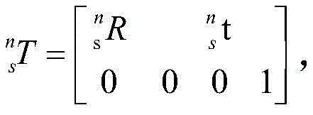


在以上技术方案的基础上,S2中标靶坐标系m到新机器人基座坐标系w的固定转换关系为:


更进一步优选的,S2中三维传感器坐标系s在新机器人基座坐标系w下的位姿态
在以上技术方案的基础上,S4中新机器人结构参数与新机器人末端位姿关系为:f(a1,...,ai,d1,...,di,α1,...,αi,θ1,...,θi)=(x,y,z,α,β,γ)。On the basis of the above technical solutions, the relationship between the structural parameters of the new robot in S4 and the end pose of the new robot is: f(a 1 ,...,a i ,d 1 ,...,d i ,α 1 ,.. .,α i ,θ 1 ,...,θ i )=(x,y,z,α,β,γ).
更进一步优选的,S4中多次移动新机器人末端,新机器人末端位姿变化量为:Further preferably, the end of the new robot is moved multiple times in S4, and the change in the pose of the end of the new robot is:

更进一步优选的,S4中通过最小二乘法优化新机器人结构参数的方法为:通过最小二乘法求出使Δf最小的18个新机器人结构参数的微小增量(Δa1,...,Δai,Δd1,...,Δdi,Δα1,...,Δαi),得到优化后的新机器人结构参数(a1,...,ai,d1,...,di,α1,...,αi)。Further preferably, the method of optimizing the structural parameters of the new robot by the least squares method in S4 is: by the least squares method, the small increments (Δa 1 ,...,Δa i of the 18 new robot structural parameters that make Δf the smallest) are obtained. ,Δd 1 ,...,Δd i ,Δα 1 ,...,Δα i ), the optimized new robot structure parameters (a 1 ,...,a i ,d 1 ,...,d i ,α 1 ,...,α i ).
本发明的一种机器人结构参数和手眼关系的统一标定模型相对于现有技术具有以下有益效果:Compared with the prior art, the unified calibration model of the robot structural parameters and the hand-eye relationship of the present invention has the following beneficial effects:
(1)本发明用三维传感器取代机器人参数标定中必须使用的光学跟踪设备,将机器人-三维传感器系统视作新的机器人系统,将三维传感器坐标系视作新机器人末端坐标系,在标定新机器人D-H参数的过程中同时标定了原机器人-三维传感器系统中的手眼关系,即一次标定完成了现有方法中机器人结构参数和手眼关系的标定工作,提高标定的精度;(1) The present invention replaces the optical tracking equipment that must be used in the robot parameter calibration with a three-dimensional sensor, regards the robot-three-dimensional sensor system as a new robot system, regards the three-dimensional sensor coordinate system as a new robot end coordinate system, and calibrates the new robot. In the process of D-H parameters, the hand-eye relationship in the original robot-3D sensor system is calibrated at the same time, that is, the calibration of the robot structure parameters and the hand-eye relationship in the existing method is completed in one calibration, and the calibration accuracy is improved;
(2)传统方法的坐标系的转换关系为:激光跟踪仪坐标系l-机器人基座坐标系w-机器人末端坐标系n-三维传感器坐标系s,而本发明的坐标系的转换关系为:标靶坐标系m-机器人基座坐标系w-三维传感器坐标系s,相比传统方法,本发明简化了标定工作,减少了计算工作,进而提高标定精度。(2) the transformation relation of the coordinate system of the traditional method is: laser tracker coordinate system l-robot base coordinate system w-robot end coordinate system n-three-dimensional sensor coordinate system s, and the transformation relation of the coordinate system of the present invention is: Target coordinate system m-robot base coordinate system w-three-dimensional sensor coordinate system s, compared with the traditional method, the invention simplifies the calibration work, reduces the calculation work, and improves the calibration accuracy.
附图说明Description of drawings
为了更清楚地说明本发明实施例或现有技术中的技术方案,下面将对实施例或现有技术描述中所需要使用的附图作简单地介绍,显而易见地,下面描述中的附图仅仅是本发明的一些实施例,对于本领域普通技术人员来讲,在不付出创造性劳动的前提下,还可以根据这些附图获得其他的附图。In order to illustrate the embodiments of the present invention or the technical solutions in the prior art more clearly, the following briefly introduces the accompanying drawings that are used in the description of the embodiments or the prior art. Obviously, the drawings in the following description are only These are some embodiments of the present invention. For those of ordinary skill in the art, other drawings can also be obtained from these drawings without creative efforts.
图1为本发明一种机器人结构参数和手眼关系的统一标定模型的流程图;Fig. 1 is the flow chart of the unified calibration model of a kind of robot structure parameter and hand-eye relationship of the present invention;
图2为本发明一种机器人结构参数和手眼关系的统一标定模型中三维传感器坐标系s作为新机器人末端坐标系的方法的流程图;Fig. 2 is a flow chart of a method for using a three-dimensional sensor coordinate system s as a new robot end coordinate system in a unified calibration model of robot structural parameters and hand-eye relationship of the present invention;
图3为本发明一种机器人结构参数和手眼关系的统一标定模型中获取三维传感器s在机器人基座坐标系w下的位姿的流程图;3 is a flow chart of obtaining the pose of the three-dimensional sensor s in the robot base coordinate system w in a unified calibration model of the robot structure parameters and the hand-eye relationship of the present invention;
图4为本发明一种机器人结构参数和手眼关系的统一标定模型中最小二乘法优化新机器人结构参数的流程图;Fig. 4 is a flow chart of the least squares method for optimizing the structural parameters of the new robot in the unified calibration model of the structural parameters of the robot and the hand-eye relationship of the present invention;
图5为传统标定方法流程图;Fig. 5 is the flow chart of traditional calibration method;
图6为传统标定方法中获取机器人末端在机器人基座坐标系w下的位姿的流程图;6 is a flowchart of obtaining the pose of the robot end in the robot base coordinate system w in the traditional calibration method;
图7为传统标定方法中求解机器人末端坐标系到三维传感器坐标系之间的转换关系的流程图。FIG. 7 is a flow chart of solving the conversion relationship between the coordinate system of the robot end and the coordinate system of the three-dimensional sensor in the traditional calibration method.
具体实施方式Detailed ways
下面将结合本发明实施方式,对本发明实施方式中的技术方案进行清楚、完整地描述,显然,所描述的实施方式仅仅是本发明一部分实施方式,而不是全部的实施方式。基于本发明中的实施方式,本领域普通技术人员在没有做出创造性劳动前提下所获得的所有其他实施方式,都属于本发明保护的范围。The technical solutions in the embodiments of the present invention will be clearly and completely described below with reference to the embodiments of the present invention. Obviously, the described embodiments are only a part of the embodiments of the present invention, but not all of the embodiments. Based on the embodiments of the present invention, all other embodiments obtained by persons of ordinary skill in the art without creative efforts shall fall within the protection scope of the present invention.
以6自由度工业机器人为例,在理论上有f(a1,...,a6,d1,...,d6,α1,...,α6,θ1,...,θ6)=(x,y,z,α,β,γ),但机器人厂商给出的机器人结构参数在实际工作中并不准确,因此需要我们对其进行标定,传统的标定方法包括以下步骤:Taking a 6-DOF industrial robot as an example, theoretically f(a 1 ,...,a 6 ,d 1 ,...,d 6 ,α 1 ,...,α 6 ,θ 1 ,.. .,θ 6 )=(x,y,z,α,β,γ), but the robot structure parameters given by the robot manufacturer are not accurate in actual work, so we need to calibrate them. The traditional calibration methods include The following steps:
S5、在机器人末端安装激光跟踪仪,获取机器人末端在机器人基座坐标系w下的位姿,如图6所示,具体包括以下步骤:S5. Install a laser tracker at the end of the robot to obtain the pose of the end of the robot in the coordinate system w of the robot base, as shown in Figure 6, which specifically includes the following steps:
S501、根据D-H方法使用四个参数ai-1、αi-1、di、θi描述串联型工业机器人的每个关节,其中参数ai-1代表关节偏移量,αi-1代表关节扭转,di代表连杆长度,θi代表绕Z轴的旋转角;S501. Use four parameters a i-1 , α i-1 , d i , θ i to describe each joint of the serial industrial robot according to the DH method, wherein the parameter a i-1 represents the joint offset, and α i-1 represents the torsion of the joint, d i represents the length of the connecting rod, and θ i represents the rotation angle around the Z axis;
S502、设机器人的第i-1个关节与第i个关节之间的变换通式为:S502, the general transformation formula between the i-1th joint and the ith joint of the robot is set as:

S503、激光跟踪仪坐标系l与机器人的基座坐标系w之间的转换关系为:


S504、机器人末端在机器人基座坐标系w下的位置和姿态为
S6、多次移动机器人末端,获取不少于18组的机器人轴转角(θ1,...,θ6)-机器人末端位姿(x,y,z,α,β,γ)之间的一一对应数据;S6. Move the end of the robot multiple times to obtain not less than 18 sets of robot axis rotation angles (θ 1 ,...,θ 6 ) - robot end poses (x, y, z, α, β, γ) between One-to-one correspondence data;
S7、多次移动机器人末端,机器人末端的位姿变化量为:S7. Move the robot end multiple times, and the pose change of the robot end is:

S8、将三维传感器安装在机器人末端,多次移动机器人末端拍摄固定标靶,根据机器人基座坐标系下标靶位置不变的约束构建方程,求解机器人末端坐标系到三维传感器坐标系之间的转换关系,如图7所示,具体包括以下步骤:S8. Install the 3D sensor on the end of the robot, move the end of the robot several times to shoot the fixed target, and construct an equation according to the constraint that the target position in the coordinate system of the robot base does not change, and solve the relationship between the coordinate system of the robot end and the coordinate system of the 3D sensor. The conversion relationship, as shown in Figure 7, specifically includes the following steps:
S801、根据连续两次运动时机器人末端坐标系在前后两次位置的变换关系A和传感器坐标系在前后两次位置的变换关系B,得到手眼关系方程AX=BX,其中,X是机器人末端坐标系与传感器坐标系的转换关系,矩阵A和矩阵B属于现有技术,在此不再累述;S801. Obtain the hand-eye relationship equation AX=BX according to the transformation relationship A of the robot end coordinate system at the front and rear positions and the sensor coordinate system transformation relationship B at the front and rear positions during two consecutive motions, where X is the robot end coordinate The conversion relationship between the system and the sensor coordinate system, the matrix A and the matrix B belong to the prior art, and will not be repeated here;
S802、设A、B分别是m×n,p×q的矩阵,采用矩阵直积算法对X进行求解,其中,矩阵A和矩阵B的直积为:
S803、由矩阵直积和线性算子vec的性质可知:

而本实施例中,将串联型工业机器人和三维传感器组成的系统(手眼系统)视作一个新机器人。本发明提供的一种机器人结构参数和手眼关系的统一标定模型,如图1所示,包括以下步骤:In this embodiment, a system (hand-eye system) composed of a serial industrial robot and a three-dimensional sensor is regarded as a new robot. A unified calibration model of robot structural parameters and hand-eye relationship provided by the present invention, as shown in FIG. 1 , includes the following steps:
S1、将串联型工业机器人和三维传感器组成的系统视作一个新机器人系统,在新机器人末端安装三维传感器,结合D-H参数模型,将三维传感器坐标系s作为新机器人末端坐标系;S1. Consider the system composed of the serial industrial robot and the three-dimensional sensor as a new robot system, install the three-dimensional sensor at the end of the new robot, and combine the D-H parameter model to take the three-dimensional sensor coordinate system s as the new robot end coordinate system;
如图2所示,将三维传感器坐标系s作为新机器人末端坐标系的方法包括以下步骤:As shown in Figure 2, the method for using the three-dimensional sensor coordinate system s as the new robot end coordinate system includes the following steps:
S101、设置D-H参数模型包括四个用于描述串联型工业机器人的每个关节参数的ai-1、αi-1、di、θi,其中参数ai-1代表关节偏移量,αi-1代表关节扭转,di代表连杆长度,θi代表绕Z轴的旋转角;S101. The DH parameter model is set to include four a i-1 , α i-1 , d i , and θ i used to describe the parameters of each joint of the tandem industrial robot, wherein the parameter a i-1 represents the joint offset, α i-1 represents the torsion of the joint, d i represents the length of the connecting rod, and θ i represents the rotation angle around the Z axis;
S102、设新机器人的第i-1个关节与第i个关节之间的变换通式为:S102, set the general transformation formula between the i-1th joint and the ith joint of the new robot as:

S103、新机器人第n-1个关节到三维传感器坐标系s的变换关系为S103. The transformation relationship from the n-1th joint of the new robot to the three-dimensional sensor coordinate system s is:


S2、用三维传感器拍摄固定标靶,获取标靶坐标系m在三维传感器坐标系s下的位姿,从而获取三维传感器坐标系s在标靶坐标系m下的位姿,根据标靶坐标系m到机器人基座坐标系w的固定转换关系获取三维传感器s在机器人基座坐标系下w的位姿,如图3所示,具体包括以下步骤:S2. Use the three-dimensional sensor to shoot the fixed target, and obtain the pose of the target coordinate system m under the three-dimensional sensor coordinate system s, so as to obtain the pose of the three-dimensional sensor coordinate system s under the target coordinate system m. According to the target coordinate system The fixed transformation relationship between m and the robot base coordinate system w obtains the pose of the three-dimensional sensor s in the robot base coordinate system w, as shown in Figure 3, which includes the following steps:
S201、设标靶坐标系m到新机器人基座坐标系w的转换关系为:


S202、三维传感器坐标系s在新机器人基座坐标系w下的位姿为
S203、由S301和S302得到(a1,...,a6,d1,...,d6,α1,...,α6,θ1,...,θ6)到(x,y,z,α,β,γ)的映射关系,通过三维模型测量得到(a1,...,a6,d1,...,d6,α1,...,α6),从而得到(θ1,...,θ6)到(x,y,z,α,β,γ)的函数关系。S203. Obtain (a 1 ,...,a 6 ,d 1 ,...,d 6 ,α 1 ,...,α 6 ,θ 1 ,...,θ 6 ) from S301 and S302 to ( The mapping relationship of x, y, z, α, β, γ) is obtained by measuring the three-dimensional model (a 1 ,...,a 6 ,d 1 ,...,d 6 ,α 1 ,...,α 6 ), thereby obtaining the functional relationship from (θ 1 ,...,θ 6 ) to (x,y,z,α,β,γ).
S3、多次移动新机器人末端,获取不少于18组的新机器人轴转角(θ1,...,θ6)-新机器人末端位姿(x,y,z,α,β,γ)之间的一一对应数据;S3. Move the end of the new robot multiple times to obtain no less than 18 sets of new robot axis rotation angles (θ 1 ,...,θ 6 )-new robot end pose (x,y,z,α,β,γ) One-to-one correspondence between data;
S4、根据新机器人结构参数与位姿关系,求解多次移动新机器人末端时,新机器人末端位姿变化量,通过最小二乘法优化新机器人结构参数,如图4所示,具体包括以下步骤:S4. According to the relationship between the structural parameters of the new robot and the pose, solve the change in the pose of the new robot when the end of the new robot is moved multiple times, and optimize the structural parameters of the new robot through the least squares method, as shown in Figure 4, which specifically includes the following steps:
S401、由现有技术知新机器人结构参数与新机器人末端位姿关系为:f(a1,...,a6,d1,...,d6,α1,...,α6,θ1,...,θ6)=(x,y,z,α,β,γ);S401 , the relationship between the structural parameters of the new robot and the terminal pose of the new robot is known from the prior art: f(a 1 ,...,a 6 ,d 1 ,...,d 6 ,α 1 ,...,α 6 ,θ 1 ,...,θ 6 )=(x,y,z,α,β,γ);
S402、多次移动新机器人末端,新机器人末端位姿变化量为:S402. Move the end of the new robot multiple times, and the change in the pose of the end of the new robot is:

S403、通过最小二乘法等数学方法求出使Δf最小的18个新机器人结构参数的微小增量(Δa1,...,Δa6,Δd1,...,Δd6,Δα1,...,Δα6),从而得到优化后的新机器人结构参数(a1,...,a6,d1,...,d6,α1,...,α6)。S403. Calculate the small increments (Δa 1 ,...,Δa 6 ,Δd 1 ,...,Δd 6 ,Δα 1 ,. ..,Δα 6 ), so as to obtain the optimized new robot structure parameters (a 1 ,...,a 6 ,d 1 ,...,d 6 ,α 1 ,...,α 6 ).
本发明的有益效果:用传感器取代机器人参数标定中必须使用的光学跟踪设备,将机器人-三维传感器系统视作新的机器人系统,将三维传感器坐标系s视作新机器人末端坐标系n,在标定新机器人D-H参数的过程中同时标定了原机器人-三维传感器系统中的手眼关系,即一次标定完成了现有方法中机器人结构参数和手眼关系的标定工作,传统方法的坐标系的转换关系为:激光跟踪仪坐标系l-机器人基座坐标系w-机器人末端坐标系n-三维传感器坐标系s,而本发明的坐标系的转换关系为:标靶坐标系m-机器人基座坐标系w-三维传感器坐标系s,相比传统方法,本发明简化了标定工作,减少了计算工作,进而提高标定精度。The beneficial effects of the invention are as follows: the optical tracking device that must be used in the robot parameter calibration is replaced by the sensor, the robot-three-dimensional sensor system is regarded as a new robot system, and the three-dimensional sensor coordinate system s is regarded as the new robot end coordinate system n. In the process of D-H parameters of the new robot, the hand-eye relationship in the original robot-3D sensor system is calibrated at the same time, that is, the calibration of the robot structure parameters and the hand-eye relationship in the existing method is completed in one calibration. The transformation relationship of the coordinate system of the traditional method is: Laser tracker coordinate system l- robot base coordinate system w- robot end coordinate system n- three-dimensional sensor coordinate system s, and the transformation relationship of the coordinate system of the present invention is: target coordinate system m- robot base coordinate system w- For the three-dimensional sensor coordinate system s, compared with the traditional method, the present invention simplifies the calibration work, reduces the calculation work, and further improves the calibration accuracy.
以上所述仅为本发明的较佳实施方式而已,并不用以限制本发明,凡在本发明的精神和原则之内,所作的任何修改、等同替换、改进等,均应包含在本发明的保护范围之内。The above description is only a preferred embodiment of the present invention, and is not intended to limit the present invention. Any modification, equivalent replacement, improvement, etc. made within the spirit and principle of the present invention shall be included in the present invention. within the scope of protection.
Claims (2)


Priority Applications (1)
| Application Number | Priority Date | Filing Date | Title |
|---|---|---|---|
| CN201910225741.2A CN109895098B (en) | 2019-03-25 | 2019-03-25 | Unified calibration model for robot structural parameters and hand-eye relationship |
Applications Claiming Priority (1)
| Application Number | Priority Date | Filing Date | Title |
|---|---|---|---|
| CN201910225741.2A CN109895098B (en) | 2019-03-25 | 2019-03-25 | Unified calibration model for robot structural parameters and hand-eye relationship |
Publications (2)
| Publication Number | Publication Date |
|---|---|
| CN109895098A CN109895098A (en) | 2019-06-18 |
| CN109895098B true CN109895098B (en) | 2020-09-29 |
Family
ID=66952503
Family Applications (1)
| Application Number | Title | Priority Date | Filing Date |
|---|---|---|---|
| CN201910225741.2A Active CN109895098B (en) | 2019-03-25 | 2019-03-25 | Unified calibration model for robot structural parameters and hand-eye relationship |
Country Status (1)
| Country | Link |
|---|---|
| CN (1) | CN109895098B (en) |
Families Citing this family (2)
| Publication number | Priority date | Publication date | Assignee | Title |
|---|---|---|---|---|
| CN110640747B (en) * | 2019-11-07 | 2023-03-24 | 上海电气集团股份有限公司 | Hand-eye calibration method and system for robot, electronic equipment and storage medium |
| CN112792814B (en) * | 2021-01-21 | 2022-06-10 | 珞石(北京)科技有限公司 | A method of zero point calibration of robotic arm based on visual signs |
Citations (2)
| Publication number | Priority date | Publication date | Assignee | Title |
|---|---|---|---|---|
| US4954762A (en) * | 1989-02-01 | 1990-09-04 | Hitachi, Ltd | Method and apparatus for controlling tracking path of working point of industrial robot |
| DE69637413T2 (en) * | 1995-12-27 | 2009-01-22 | Fanuc Ltd. | COMPOSITE DETECTION SYSTEM FOR ROBOTS |
Family Cites Families (5)
| Publication number | Priority date | Publication date | Assignee | Title |
|---|---|---|---|---|
| JP3859574B2 (en) * | 2002-10-23 | 2006-12-20 | ファナック株式会社 | 3D visual sensor |
| CN101660904A (en) * | 2009-09-22 | 2010-03-03 | 大连海事大学 | Kinematics calibration method of measurement robot |
| CN104827480A (en) * | 2014-02-11 | 2015-08-12 | 泰科电子(上海)有限公司 | Automatic calibration method of robot system |
| CN105014679A (en) * | 2015-08-03 | 2015-11-04 | 华中科技大学无锡研究院 | Robot hand and eye calibrating method based on scanner |
| CN108346165B (en) * | 2018-01-30 | 2020-10-30 | 深圳市易尚展示股份有限公司 | Method and device for joint calibration of robot and three-dimensional sensing component |
-
2019
- 2019-03-25 CN CN201910225741.2A patent/CN109895098B/en active Active
Patent Citations (2)
| Publication number | Priority date | Publication date | Assignee | Title |
|---|---|---|---|---|
| US4954762A (en) * | 1989-02-01 | 1990-09-04 | Hitachi, Ltd | Method and apparatus for controlling tracking path of working point of industrial robot |
| DE69637413T2 (en) * | 1995-12-27 | 2009-01-22 | Fanuc Ltd. | COMPOSITE DETECTION SYSTEM FOR ROBOTS |
Also Published As
| Publication number | Publication date |
|---|---|
| CN109895098A (en) | 2019-06-18 |
Similar Documents
| Publication | Publication Date | Title |
|---|---|---|
| CN108489395B (en) | Vision measurement system structural parameters calibration and affine coordinate system construction method and system | |
| CN107738254B (en) | A method and system for converting and calibrating a manipulator coordinate system | |
| CN110253574B (en) | Multi-task mechanical arm pose detection and error compensation method | |
| CN107175660B (en) | A kind of six-freedom degree robot kinematics scaling method based on monocular vision | |
| CN107972071B (en) | A kind of industrial robot link parameters scaling method based on distal point plane restriction | |
| CN105773609A (en) | Robot kinematics calibration method based on vision measurement and distance error model | |
| CN107817682B (en) | Space manipulator on-orbit calibration method and system based on hand-eye camera | |
| CN117506918B (en) | Industrial robot tail end pose calibration method | |
| CN114001653B (en) | A method for calibrating the center point of robot tool | |
| CN112971984B (en) | Coordinate registration method based on integrated surgical robot | |
| CN108297100A (en) | Mechanical arm parameter calibration method, device and system and mechanical arm | |
| JP7097722B2 (en) | How to restore the location information of the robot | |
| CN113781558B (en) | A robot vision positioning method that decouples attitude and position | |
| CN115187672B (en) | Geometric error calibration methods, devices, multi-axis motion systems, and storage media | |
| CN109623822B (en) | Robot hand-eye calibration method | |
| CN117381800B (en) | A hand-eye calibration method and system | |
| TWI793044B (en) | Eye-hand calibration method and eye-hand calibration device for robot arm | |
| CN116061196B (en) | A method and system for calibrating kinematic parameters of a multi-axis motion platform | |
| CN116117797B (en) | A pose graph-based method for correcting pose errors and calibration errors of hand-eye systems | |
| CN116038721B (en) | A hand-eye calibration method and system without kinematics participation | |
| CN113211445A (en) | Robot parameter calibration method, device, equipment and storage medium | |
| CN109895098B (en) | Unified calibration model for robot structural parameters and hand-eye relationship | |
| CN116394254A (en) | Robot zero point calibration method, device, and computer storage medium | |
| CN111390914A (en) | Robot zero position and tool coordinate calibration method | |
| CN113459084A (en) | Robot parameter calibration method, device, equipment and storage medium |
Legal Events
| Date | Code | Title | Description |
|---|---|---|---|
| PB01 | Publication | ||
| PB01 | Publication | ||
| SE01 | Entry into force of request for substantive examination | ||
| SE01 | Entry into force of request for substantive examination | ||
| GR01 | Patent grant | ||
| GR01 | Patent grant |