CN109844475B - Device for determining the quality of assembly of threaded tubular joints - Google Patents
Device for determining the quality of assembly of threaded tubular joints Download PDFInfo
- Publication number
- CN109844475B CN109844475B CN201780060907.9A CN201780060907A CN109844475B CN 109844475 B CN109844475 B CN 109844475B CN 201780060907 A CN201780060907 A CN 201780060907A CN 109844475 B CN109844475 B CN 109844475B
- Authority
- CN
- China
- Prior art keywords
- assembly
- temperature
- tubular
- electronics
- measuring
- Prior art date
- Legal status (The legal status is an assumption and is not a legal conclusion. Google has not performed a legal analysis and makes no representation as to the accuracy of the status listed.)
- Expired - Fee Related
Links
Images


Classifications
-
- E—FIXED CONSTRUCTIONS
- E21—EARTH OR ROCK DRILLING; MINING
- E21B—EARTH OR ROCK DRILLING; OBTAINING OIL, GAS, WATER, SOLUBLE OR MELTABLE MATERIALS OR A SLURRY OF MINERALS FROM WELLS
- E21B19/00—Handling rods, casings, tubes or the like outside the borehole, e.g. in the derrick; Apparatus for feeding the rods or cables
- E21B19/16—Connecting or disconnecting pipe couplings or joints
- E21B19/165—Control or monitoring arrangements therefor
-
- G—PHYSICS
- G01—MEASURING; TESTING
- G01J—MEASUREMENT OF INTENSITY, VELOCITY, SPECTRAL CONTENT, POLARISATION, PHASE OR PULSE CHARACTERISTICS OF INFRARED, VISIBLE OR ULTRAVIOLET LIGHT; COLORIMETRY; RADIATION PYROMETRY
- G01J5/00—Radiation pyrometry, e.g. infrared or optical thermometry
- G01J5/02—Constructional details
- G01J5/0205—Mechanical elements; Supports for optical elements
-
- G—PHYSICS
- G01—MEASURING; TESTING
- G01J—MEASUREMENT OF INTENSITY, VELOCITY, SPECTRAL CONTENT, POLARISATION, PHASE OR PULSE CHARACTERISTICS OF INFRARED, VISIBLE OR ULTRAVIOLET LIGHT; COLORIMETRY; RADIATION PYROMETRY
- G01J5/00—Radiation pyrometry, e.g. infrared or optical thermometry
- G01J5/02—Constructional details
- G01J5/025—Interfacing a pyrometer to an external device or network; User interface
-
- G—PHYSICS
- G01—MEASURING; TESTING
- G01J—MEASUREMENT OF INTENSITY, VELOCITY, SPECTRAL CONTENT, POLARISATION, PHASE OR PULSE CHARACTERISTICS OF INFRARED, VISIBLE OR ULTRAVIOLET LIGHT; COLORIMETRY; RADIATION PYROMETRY
- G01J5/00—Radiation pyrometry, e.g. infrared or optical thermometry
- G01J5/02—Constructional details
- G01J5/04—Casings
- G01J5/041—Mountings in enclosures or in a particular environment
- G01J5/044—Environment with strong vibrations or shocks
-
- G—PHYSICS
- G01—MEASURING; TESTING
- G01J—MEASUREMENT OF INTENSITY, VELOCITY, SPECTRAL CONTENT, POLARISATION, PHASE OR PULSE CHARACTERISTICS OF INFRARED, VISIBLE OR ULTRAVIOLET LIGHT; COLORIMETRY; RADIATION PYROMETRY
- G01J5/00—Radiation pyrometry, e.g. infrared or optical thermometry
- G01J5/02—Constructional details
- G01J5/04—Casings
- G01J5/048—Protective parts
-
- G—PHYSICS
- G01—MEASURING; TESTING
- G01J—MEASUREMENT OF INTENSITY, VELOCITY, SPECTRAL CONTENT, POLARISATION, PHASE OR PULSE CHARACTERISTICS OF INFRARED, VISIBLE OR ULTRAVIOLET LIGHT; COLORIMETRY; RADIATION PYROMETRY
- G01J5/00—Radiation pyrometry, e.g. infrared or optical thermometry
- G01J5/02—Constructional details
- G01J5/08—Optical arrangements
- G01J5/0881—Compact construction
-
- G—PHYSICS
- G01—MEASURING; TESTING
- G01J—MEASUREMENT OF INTENSITY, VELOCITY, SPECTRAL CONTENT, POLARISATION, PHASE OR PULSE CHARACTERISTICS OF INFRARED, VISIBLE OR ULTRAVIOLET LIGHT; COLORIMETRY; RADIATION PYROMETRY
- G01J5/00—Radiation pyrometry, e.g. infrared or optical thermometry
- G01J5/10—Radiation pyrometry, e.g. infrared or optical thermometry using electric radiation detectors
- G01J5/20—Radiation pyrometry, e.g. infrared or optical thermometry using electric radiation detectors using resistors, thermistors or semiconductors sensitive to radiation, e.g. photoconductive devices
-
- G—PHYSICS
- G01—MEASURING; TESTING
- G01K—MEASURING TEMPERATURE; MEASURING QUANTITY OF HEAT; THERMALLY-SENSITIVE ELEMENTS NOT OTHERWISE PROVIDED FOR
- G01K1/00—Details of thermometers not specially adapted for particular types of thermometer
- G01K1/02—Means for indicating or recording specially adapted for thermometers
- G01K1/026—Means for indicating or recording specially adapted for thermometers arrangements for monitoring a plurality of temperatures, e.g. by multiplexing
-
- G—PHYSICS
- G01—MEASURING; TESTING
- G01K—MEASURING TEMPERATURE; MEASURING QUANTITY OF HEAT; THERMALLY-SENSITIVE ELEMENTS NOT OTHERWISE PROVIDED FOR
- G01K1/00—Details of thermometers not specially adapted for particular types of thermometer
- G01K1/14—Supports; Fastening devices; Arrangements for mounting thermometers in particular locations
- G01K1/143—Supports; Fastening devices; Arrangements for mounting thermometers in particular locations for measuring surface temperatures
-
- G—PHYSICS
- G01—MEASURING; TESTING
- G01K—MEASURING TEMPERATURE; MEASURING QUANTITY OF HEAT; THERMALLY-SENSITIVE ELEMENTS NOT OTHERWISE PROVIDED FOR
- G01K7/00—Measuring temperature based on the use of electric or magnetic elements directly sensitive to heat ; Power supply therefor, e.g. using thermoelectric elements
- G01K7/02—Measuring temperature based on the use of electric or magnetic elements directly sensitive to heat ; Power supply therefor, e.g. using thermoelectric elements using thermoelectric elements, e.g. thermocouples
-
- G—PHYSICS
- G01—MEASURING; TESTING
- G01K—MEASURING TEMPERATURE; MEASURING QUANTITY OF HEAT; THERMALLY-SENSITIVE ELEMENTS NOT OTHERWISE PROVIDED FOR
- G01K7/00—Measuring temperature based on the use of electric or magnetic elements directly sensitive to heat ; Power supply therefor, e.g. using thermoelectric elements
- G01K7/16—Measuring temperature based on the use of electric or magnetic elements directly sensitive to heat ; Power supply therefor, e.g. using thermoelectric elements using resistive elements
Landscapes
- Physics & Mathematics (AREA)
- General Physics & Mathematics (AREA)
- Spectroscopy & Molecular Physics (AREA)
- Engineering & Computer Science (AREA)
- Mining & Mineral Resources (AREA)
- Geology (AREA)
- Life Sciences & Earth Sciences (AREA)
- Fluid Mechanics (AREA)
- Environmental & Geological Engineering (AREA)
- Mechanical Engineering (AREA)
- General Life Sciences & Earth Sciences (AREA)
- Geochemistry & Mineralogy (AREA)
- Human Computer Interaction (AREA)
- Testing Of Devices, Machine Parts, Or Other Structures Thereof (AREA)
- Non-Disconnectible Joints And Screw-Threaded Joints (AREA)
- Lining Or Joining Of Plastics Or The Like (AREA)
- Testing Or Calibration Of Command Recording Devices (AREA)
- Measuring Temperature Or Quantity Of Heat (AREA)
Abstract
An apparatus for determining the quality of the make-up of a threaded tubular component comprises a frame (2) arranged to be mounted on a portion of the outer surface of the threaded tubular component; at least one measuring member (3) comprising a contact layer (4) comprising a plurality of temperature sensors (5) arranged for measuring magnitudes representative of the temperature at a plurality of points E (i, j) of the outer surface of the end portion of the tubular assembly.
Description
Technical Field
The present invention relates to the field of threaded tubular joints, and more particularly to an attachment for determining the quality of make-up of a threaded tubular joint.
Background
"threaded tubular joint" refers to the assembly of two tubular components assembled together by a thread, the "components" being any element or accessory used for drilling or producing oil and/or gas wells and comprising at least one connection or connection, or threaded end.
The assembly may be a relatively long tubular element (in particular about ten metres long), such as a tube, or a tubular sleeve of several tens of centimetres long, or an attachment of these tubular elements (suspension means, section-changing parts, safety valves, connections for drill pipes, subassemblies, etc.). These components are typically made of steel. The device is particularly suitable for elements made of stainless steel, elements with high chromium content such as 13Cr or CRA steel; these steels are particularly sensitive to seizure.
The components are typically assembled with each other for lowering into a hydrocarbon or similar well and constituting a drill string, casing string or liner or tubing string.
The specification API 5CT issued by the American Petroleum Institute (API), corresponding to the standard ISO 11960:2004 issued by the international organization for standardization (ISO), manages pipes used as casing or tubing strings, and the specification API 5B defines standard threads for these pipes.
The specification API 7 defines a threaded connection with a shoulder for rotating a drill rod.
Manufacturers of assemblies of threaded tubular joints have also developed so-called premium threaded joints with specific thread geometries, and specific parts that give them better service properties, in particular of materials that are mechanically resistant to wear and sealing, and resistant to corrosion, in particular to sulphide corrosion.
The aforementioned components may include a pin end for tightening onto a box end of another drilling or production component to form an assembled joint that must have high mechanical and sealing integrity under very high mechanical impacts, as well as corrosion resistance. It is therefore of critical importance that their male and female ends are damaged, contaminated or destroyed as little as possible between the moment they leave their production line and the moment they are used, and also between two successive uses. The use of a protection makes it possible to protect not only the threads but also any bearing surfaces and stops each having the specific and complementary functions of these elements from corrosion, dust and shocks (or impacts), in particular in order to guarantee sealing during the use phase. However, it may happen that an end portion is damaged and it is not detected before assembly. It is also possible that at the moment of assembly, the elements to be assembled are positioned incorrectly. There is therefore a risk of seizure during makeup, causing local material stripping, possibly undesirable plastic deformation, at a portion of the thread, even at other functional surfaces such as the stop or the sealing bearing surface. Such seizing may result in a degradation of the mechanical quality or the sealing quality of the joint.
Therefore, there is a need to detect the occurrence of seizing between functional surfaces during the assembly of the two ends of a tubular assembly.
A method for controlling the tightening state of threaded tubular joints is known in the prior art, in particular from document JP 6-221475, in which the torque amplitude is analyzed during the tightening operation as a function of the number of tightening turns carried out. The torque change is used to detect the occurrence of seizure. However, this method may lead to erroneous interpretations, in particular because the tightening torque variations depend on the actual dimensions in their machining tolerances. Furthermore, this method is generally based on reaching a torque threshold according to the screwing forward state, and the fixing of this value comes from a compromise between the possibility of detecting the occurrence of all the seizure brakes during makeup, and the frequency of false-positive resulting detections, the expression meaning that implementing this method leads to a seizure brake diagnosis, while in fact there are no seizure brakes during makeup. It is also possible that the snap brake suddenly appears during assembly producing tightening torque variations similar to the desired result, while functional surfaces such as stops or bearing surfaces are not the source of the generated torque: no seizure was detected by the method of JP 6-221475 and the resulting joint was not sealed.
The present invention aims to improve the detection of the brake seizure phenomenon while minimizing the detection of false alarms.
The applicant has noted that the plastic deformation and peeling of the material that occurs during the brake-biting generates heating. Furthermore, the assembly operation itself generates heat, in particular due to the surfaces rubbing against each other. This is the case for example of thread bottoms, sealing back-up faces or other functional surfaces of the thread ends. These heats are local, but because of heat conduction within the material of the threaded end, they cause the temperature within the end to change to the outer surface of the end.
Therefore, there is the possibility of detecting the seizure by a method and a device which measure the temperature variations during the makeup of the two threaded ends and which are able to detect from these measurements whether the temperature variations are caused by the occurrence of seizure.
The applicant has developed a device capable of measuring the temperature variation of a plurality of points of the outer surface of one end portion, so that it can be used by an operator on an oil platform.
Disclosure of Invention
1. The object of the present invention is a device for determining the quality of the makeup of a threaded tubular component, comprising:
-a housing (2) comprising a cylindrical inner space (20) having an axis (21) and arranged to be mounted on a portion of the outer surface of the threaded tubular assembly;
-at least one measuring member (3) located between the frame (2) and the inner space (20), the measuring member comprising a contact layer (4) comprising a plurality of temperature sensors (5) arranged for measuring magnitudes representative of the temperature at a plurality of locations E (i, j) of the outer surface of the end of the tubular assembly;
-first acquisition electronics (33) connected to the plurality of temperature sensors (5) and able to process at least part of the signals generated by the temperature sensors (5).
In one embodiment, the device may include a plurality of measurement bands (31) distributed about an axis (21) of the device.
In one embodiment, the device may be a screw down guide for an oil production tubular assembly.
The temperature sensor (5) may be selected from a thermocouple, a thermistor, a microbolometer.
The temperature sensors (5) are distributed on the flexible substrate to form a temperature sensor (5) matrix (51).
In one embodiment, the temperature sensor (5) may be a thermistor and the flexible substrate is made of polyimide.
The contact layer (4) may comprise a thermally conductive and electrically insulating layer arranged at least partially between the temperature sensor (5) and the inner space (20).
The contact layer (4) may comprise a protective layer (41) arranged to protect the temperature sensor (5).
The protective layer (41) may be a steel sheet shaped to have a circular profile.
In one embodiment, the device may include a buffer layer (9) between the frame (2) and the contact layer (4).
The cushioning layer (9) may comprise resilient members selected from the group consisting of garter springs, Clover dome spring washers, wave washers, dome springs, elastomeric materials, silicone or neoprene foam.
The cushioning layer (9) may include a rigid profiled element (92).
The frame (2) may comprise a positioning stop (7).
In one embodiment, the first acquisition electronics (33) may comprise a plurality of acquisition electronics units (34) connected to collection electronics (35) of the FPGA programmable electronic circuit type.
In one embodiment, the apparatus includes second processing electronics (36) capable of determining, based on at least one time detection law, the occurrence of seizure or the destruction of at least a portion of a component of the tubular joint during the assembly of two threaded tubular assemblies.
The first acquisition electronics (33) and the second processing electronics (36) can be connected by a wireless link of the WiFi type or bluetooth type or by a wired link of the ethernet type.
The second processing electronics may comprise software for processing and storing the measured values.
The invention is also a method of using a device according to the invention, comprising the steps of:
-determining a set of values T0(i, j) representing the temperature at a plurality of points E (i, j) of the outer surface of one end (11) of the tubular assembly at the start of assembly of this tubular assembly with another corresponding tubular assembly;
-determining a further set of values T (i, j) representative of the temperature at a plurality of points E (i, j) of the outer surface of one end portion (11) during assembly;
-calculating the temperature during assembly T (i, j) and the temperature at the start of assembly T (i, j) for each site E (i, j)0(i, j) difference between;
when the difference T is0(i,j)-T0(i, j) exceeds a predetermined threshold value DeltaT for at least one location E (i, j)seuil(i, j) issuing a brake seizure diagnosis.
In one embodiment variant, the method further comprises the following steps:
-calculating the speed of temperature change V for at least one group of locations E (i, j)T(i,j);
Speed V when temperature changesT(i, j) exceeds a predetermined variation threshold Δ VT(i, j) issuing a brake seizure diagnosis.
Drawings
The features and advantages of the present invention will become apparent upon a study of the following detailed description and the accompanying drawings, in which:
figure 1 shows a schematic view of a threaded tubular component and a portion of one of its ends;
figure 2 shows a schematic partial perspective view of one embodiment of the device according to the invention placed around the female end of a threaded tubular component, in the open position;
FIG. 3 is a perspective view of an embodiment of the invention, in the closed position;
FIG. 4 is a perspective view of a plurality of measuring members according to an embodiment of the invention;
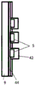
FIG. 5 is a truncated perspective view of a measuring tape according to an embodiment of the invention;
figures 6a and 6b are cross-sectional views of embodiments of a measuring tape according to the invention;
figure 7 is a perspective view of the acquisition electronics and the measurement tape not mounted on the rack according to one embodiment of the invention.
Detailed Description
The drawings may not only serve to supplement the invention but also to contribute to its definition, if necessary. The drawings do not limit the scope of the invention.
The aim of the invention is to determine the quality of the assembly of two threaded components by detecting the occurrence of damage to the threaded portions, and/or to the sealing bearing surfaces and/or to the stop during the assembly of the two threaded ends of a tubular component into a threaded joint.
"female end" refers to the portion of the assembly provided with a machined and/or corrected surface intended to form, together with the corresponding male portion, a joint, and "body" refers to the portion of the assembly located outside this portion and provided with a surface usually coming from rolling. The box end typically has one or more threads on the inner sidewall and is configured to be assembled to a corresponding box end having one or more corresponding threads on the outer sidewall of the assembly.
Fig. 1 shows a tubular assembly (10) and a female end or connection (11). The end is provided with a thread (12) and may further comprise a sealing surface (17), a stop (18). Some connections may include threads or sealing bearing surfaces or stops. The tubular assembly shown is of the "threaded coupling" type. In practice, it comprises a tubular body (10) provided with a first external thread (14a) and a sleeve (15) provided with a second internal thread (14b) which can be screwed onto the first external thread (14a) of the tubular body (10).
The sleeve (15) comprises a thread (12) for screwing on one end of another tubular assembly. In fig. 1, the sleeve comprises the female end of a tubular assembly (10) and is intended to be screwed onto the male end of another tubular assembly. The thread (12) may be different from the second internal thread (14b), in other words, the sleeve does not have to be symmetrical. The sleeve (15) further comprises a field end face (16).
Alternatively, there are so-called "integrated" tubular assemblies which do not comprise a sleeve and in which the male and/or female ends are formed directly.
The thread (12) may comprise at least one so-called portion with a complete thread, and the thread may also comprise one or more so-called portions with an incomplete or vanishing thread. The incomplete thread allows to reduce the bulk of the threaded joint and/or to allow a better flow of possible lubricating oil deposited on the connection before makeup.
The seizure phenomenon has several aspects. First, it may affect different functional parts of the connection: threads, sealing surfaces or sealing bearing surfaces, stops at complete or incomplete threads. Second, the bite brake may be characterized by its extent: it may involve the surface of a portion of the thread portion, for example, having a few centimeters of material stripping at the flanks of the junction of a single full thread; in more severe cases it may also involve damage to a plurality of successive spirals on the angular sector of the threading, for example the seizure may be the destruction of 5 successive spirals on an angular sector of 15 °.
The bite brake may also be characterized by its strength. A very slight snap brake allows an attempt to assemble the assembly directly; slight bite brakes allow for possible manual repair of damaged surfaces and a second assembly attempt in the field; moderate seizure with material stripping can result in rejection of the associated tubular member; a severe seizure with a damaged material peel-off with a geometry with a functional surface may result in rejection of the relevant tubular component.
The components brought uphole are subject to transport, handling, storage in aggressive environments, which means that assembly of the components does not proceed under conditions as ideal and controlled as the factory environment. Prior to assembly of the components, the components may be incorrectly positioned relative to one another. These external factors may cause assembly defects with low probability, but the consequences are very severe for the integrity of the drill string and the gas or oil well.
In a well or oil well, the assemblies are assembled one after the other on the last assembly of a string of tubulars which is gradually lowered into the well. Typically, the components are placed in a vertical position for assembly, so that they have a high end and a low end for assembly at the high end of the last component introduced in the drill string. During this operation, the assembly is typically carried and suspended by its high end. The assembly is guided by an operator who operates its lower end.
In order to limit the oscillation of the assembly and to avoid impacts, in particular on the functional parts of the ends to be assembled to each other, screwing guides are generally used.
A tightening guide (commonly known in the technical field of tubular assemblies for oil and gas wells as "stabbing shoes") generally comprises a tapered guide portion for bringing the male end into position for assembly on the corresponding female end. The device also functions to protect the threads of the male end from impacts during the approach phase. Patent US 4599778 describes such a screw-down guide.
The applicant has found that it is particularly useful to integrate the device of the invention into a screwing guide, since this allows to reduce the number of fittings and operations to be carried out during the assembly of the tubular assembly, and since this has the risk of reducing the improper positioning of the device according to the invention.
The assembly device (1) of the invention of fig. 2 comprises a frame (2) able to be positioned and mounted on the end of a tubular assembly (11). The housing has an axis (21) and a substantially cylindrical interior space (20) capable of receiving a portion of the cylindrical tubular element. The frame (2) is generally made in two parts to facilitate its handling around the tubular element. The two parts may be mounted to pivot relative to each other.
The chassis (2) may comprise positioning stops (7) allowing a proper placement, in particular an axial placement, of the chassis (2). When the device is used on a screw-coupling type connection, the positioning stop (7) is arranged to be able to bear on the field end face (16). The positioning stop (7) allows repeatable axial positioning of the device and therefore more precise knowledge of the axial positioning of the temperature sensor (5) (not visible in fig. 2) with respect to the functional surface of the joint.
The assembly device (1) further comprises a measuring member (3). The measuring member (3) has a substantially cylindrical internal shape so as to approximate the shape of the external surface of the end of the tubular assembly (11) or so as to be able to conform to the external surface of the end of the tubular assembly (11). The measuring member (3) is thus positioned between the chassis (2) and the inner space (20).
The measuring member (3) comprises at least one measuring band (31). Fig. 2 shows a plurality of measuring strips (31). The measuring tape (31) is generally distributed to cover a large part of the outer side surface of one end. Each measuring band (31) comprises a contact layer (4) comprising a plurality of temperature sensors (5) for measuring a quantity representative of the temperature of a plurality of points of the outer surface of the end of the tubular assembly (11). The contact layer (4) integrated on the chassis (2) has the advantage of providing a compact solution and of not taking up platform space compared to thermal camera systems. This has several advantages: a system using thermal cameras would require 3 thermal cameras to make 360 ° measurements around the tubular assembly, would be difficult to use in the field, and the cameras could be obscured by the tool or operator. In addition, the contact layer (4) is protected by the frame (2) from external heat radiation from operators, the sun, equipment surrounding the well.
The measuring strips (31) of the embodiment of fig. 2 are arranged vertically and distributed radially. Alternatively, the measuring strips are arranged horizontally and distributed axially. The advantage of a vertical arrangement is that it allows to implement measurement bands identical to each other for devices adapted to different outer diameters of the pipe or end.
Fig. 5 is a cut-away perspective view of the measuring tape (31). The measuring belt (31) comprises a plurality of temperature sensors (5) distributed over a substrate (44). The base body (44) facilitates the assembly of the contact layer (5) and improves the positioning accuracy of the sensor (5). Advantageously, the substrate (44) is a flexible substrate. The flexibility of the support (44) allows for ease of positioning of the sensor on the outer surface of one end (11) of the tubular assembly. The mounting may be by gluing or welding. The flexible substrate (44) may be, for example, a sheet made of polyimide such as Kapton sold by DuPont.
In a first embodiment variant, the contact layer (4) comprises a temperature sensor (5) of the thermistor type.
In a second variant of embodiment, the contact layer (4) comprises a temperature sensor (5) of the thermocouple type, for example a thermocouple of the type TC2741 sold by Minco Products inc. In this embodiment variant, the contact layer (4) may comprise a thermocouple film.
In a third variant of embodiment, the contact layer (4) comprises a temperature sensor of the microbolometer type, for example the model sold by the INO company. Bolometers allow temperature measurement from radiant energy. The principle of bolometers is to convert the radiant energy reaching an absorbing material, usually connected to a thermistor, into an electrical characteristic representative of the radiation. In this latter variant of embodiment, the contact layer (4) may not be in contact with the outer surface of the end of the tubular assembly and may maintain acceptable measurement performance, the bolometer not necessarily being in contact with the surface of the object being measured, the bolometer taking the measurement of the infrared emission. The use of bolometers thus allows solving the measurement quality problems related to possible geometrical defects of the outer surface of the end of the tubular assembly (11). When using a bolometer, it is not possible to use a protective layer in close proximity to the measurement surface of the bolometer. If a protective layer is used, the protective layer must be drilled so as not to cover the bolometer. But sensors of the microbolometer type have disadvantages compared to thermocouples and thermistors because they are very sensitive to dirt.
In another embodiment variant, the contact layer (4) may comprise a combination of different types of sensors selected from thermocouples, thermistors and bolometers.
The contact layer (4) shown in fig. 5 also comprises a protective layer (41) that protects the sensor from wear. The protective layer (41) can be embodied in the form of a metal foil, which allows good protection against impacts, friction and wear. A metal type material is preferred because it is the same as the material of the tubular assembly and therefore behaves similarly in terms of thermal conductivity. The foil may be thin in order to have a certain flexibility. The foil (41b) may be formed such that it has a substantially circular profile in order to better follow the circular profile of the surface of the tubular assembly.
The contact layer (4) may also comprise a thermally and electrically conductive insulating layer (42) covering the receptor surface of the sensor (5) in order to be positioned between the sensor and the outer surface of the end of the component (11) and in order to better transfer heat towards the sensor. Examples of suitable materials from which the thermally and electrically insulating layer (42) may be flexible to improve the ability of the measurement member (3) to conform to the outer surface of the tubular assembly and to ensure optimal coupling between the sensor (5) and the surface to be measured are PC94 and PC93, products from t-Global Technology, inc, or TPCM FSF-52 of Laird Technology.
When the protective layer (41) is present, the thermally conductive and electrically insulating layer (42) is located between the protective layer (41) and the substrate (44).
As can be seen on fig. 6b, the contact layer (4) may further comprise an insulating layer (44) allowing thermal insulation of the temperature sensor (5). This insulating layer is arranged to thermally insulate the sensor in addition to the functional measuring surface and to define a measuring direction which is generally directed towards the surface whose temperature is to be measured. The insulating layer allows for improved measurement goals.
In one embodiment, as shown in fig. 5, the device according to the invention may further comprise a buffer layer (9) between the frame (2) and the contact layer (4). This buffer layer has ductile properties and has a certain elasticity, in fact the role of said buffer layer (9) being to maintain contact between the contact layer (4) and the outer surface of the end of the tubular component (11) by compensating for dimensional variations of said end, such as variations related to diameter tolerances, cylindricity defects.
In one embodiment variant, the damping layer (9) comprises an elastic material, such as silicone or neoprene foam.
In other embodiment variants, the cushioning layer (9) may comprise a spring selected from the group consisting of a Clover dome spring washer, a wave washer, a dome spring, a garter spring.
The damping layer (9) can also comprise, by combination with one of the above-mentioned embodiment variants, a rigid support (92) between the elastic support with the elastic structure described above and the contact layer (4). The rigid support (92) is thus located between the elastic support (91) of the cushioning layer (9) and the contact layer (4). The rigid support may have a concave shaped inner surface (93) which abuts the contact layer (4) so as to impart a concave shape to the contact layer (4), the concave shape of the contact layer allowing the contact layer to better conform to the convex outer surface of the tubular assembly.
In the embodiment of the device whose measuring band is shown in fig. 4 and 5, the device according to the invention comprises a plurality of measuring members in the form of measuring bands (31) distributed over the circumference surrounding the inner space (20).
As shown on fig. 7, each measuring band (31) of the measuring member (3) comprises a contact layer (4) comprising a plurality of sensors (5) mounted on a supporting layer (44) for measuring a quantity representative of the temperature of a plurality of points of the outer surface of the end of the tubular assembly (11). The plurality of sensors is organized in a matrix inside each measuring band (31) of the measuring member (3). For example, each matrix may include 8 columns of 32 sensors. In each measuring strip (31), a matrix (51) of temperature sensors (5) is connected to an acquisition electronics unit (34) by a flexible connecting strip (52). The flexible connection strip facilitates compact packaging of the electronics into the measuring device.
Each acquisition electronics unit (34) of the device forms part of the first acquisition electronics (33). Each acquisition electronics unit (34) is connected to collection electronics. The first acquisition electronics therefore comprise one or more acquisition electronics units and collection electronics (35) visible on fig. (3).
Each measuring strip (31) comprises a contact layer (4). This allows an improved coupling of the matrix of sensors (5) to the outer surface of the tubular assembly. This also allows thermally decoupling the sensor matrices from each other, which may be advantageous when the resolution is low.
Each measuring strip (31) comprises a damping layer (9). This allows the sensor (5) matrices to be partially mechanically separated for better coupling between each sensor matrix and the surface of the tubular assembly despite geometrical imperfections in the tubular assembly.
In the embodiment of fig. 5, the cushioning layer (9) comprises neoprene foam. The cushioning layer (9) further comprises a rigid support (92) in the form of a shaped metal sheet.
In the embodiment shown in fig. 4 and 5, the measuring bands (31) are arranged distributed over the circumference. Alternatively, the measuring bands (31) may be arranged in an axial distribution. The embodiment shown is industrially advantageous, since it allows the implementation of standardized measuring means. The device according to the invention is then adapted to the diameter of the tubular assembly measured by the number of segments (31) installed: the larger the diameter, the more integrally identical measuring strips (31) can be installed.
Advantageously, the device according to the invention is a screwing guide (or stabbing shoe) and comprises an upper portion (6) comprising guide means for guiding the end of the male component. For example, the portion includes a tapered inner surface (6b) defining a tapered interior space. The part is the so-called upper part, since this part is the part that is arranged upwards in normal use on site of the tightening guide, a component is usually brought from above to tighten a tubular component to the drill string.
The frame (2) and the at least one measuring member (3) are thus comprised in the lower part of the tightening guide and the conical inner space (6b) provided as the upper part is open in the continuation of the cylindrical inner space (20). The device according to the invention is therefore integrated into a tool, the use of which is familiar to the operator in the field. This therefore allows to simplify the field use of the device according to the invention.
Advantageously, the assembly device according to the invention comprises positioning means which position the device so that the measuring portion is correctly positioned on the outer surface of the female end of the assembly at least at a portion of the threading. "at. Repeatable correct positioning allows the impact of this positioning on the performed measurements representative of the temperature to be minimized. This positioning means may be a positioning stop (7). For use of the device on a threaded coupling type joint, this positioning stop (7) may be arranged to bear on the field end face (or field end) of the sleeve. It will be appreciated that this stop may be arranged differently depending on the geometry of the engagement member. If it is an integrated joint provided with a thickened portion, the stop can have a shape complementary to the outer surface of said thickened portion or the change in the outer diameter of the joint. Alternatively, the stop may be replaced by a visual marker that can be used by the operator to axially align the device, for example by placing the visual marker at the level of the end of the female connection.
The device according to the invention may be provided with a closure member enabling the tightening guide to be closed and held closed around the tubular assembly or to be opened in order to detach the device from the tubular assembly after use. The closing means may be arranged to provide sufficient locking force to the device to allow the device to be held on the tubular assembly without external assistance and to ensure that the contact layer (4) is brought into contact with the tubular assembly, in particular by compressing the cushioning layer. The closure member of the device is typically that of a screw down guide already in use on site. The closure member may be a lever type fastener (22) of figure 3. Alternatively, the fastening element may also be a fastening element of the type described in patent US 4599778.
According to one aspect shown in fig. 7, the assembly device according to the invention comprises, on each measuring strip (31), a first acquisition electronics (33) connected to a plurality of sensors (5) arranged in the contact layer (4). Preferably, the sensors (5) are arranged in a sensor matrix (33).
First acquisition electronics (33) connected to the sensors (5) of the measuring tape (31) collect the signals from said sensors (33). The first acquisition electronics (33) can comprise, on each measuring strip (31), an acquisition electronics unit (34) which collects signals representative of the temperature of the sensors (5) of the measuring strip (31) on which the unit (34) is arranged; and the first acquisition electronics (33) may therefore also comprise a collection electronics unit (35) which collects all data from the different acquisition electronics units (34). Thus, each acquisition electronics unit (34) is able to convert the signal representative of the temperature from the sensor (33) into a data stream, which is then transmitted by an asynchronous link to the collection electronics unit (35). For example, the asynchronous link is of the RS232 type and the collection electronic unit (35) is an electronic card of the FPGA type. The first acquisition electronics (33) comprise power supply means for powering the sensor, an analog/digital signal conversion module, processing means and communication means.
The first acquisition electronics (33) are able to associate each signal with a position corresponding to a sensor, so as to establish a position-temperature matrix whose values T (i, j) represent the measured temperatures, where i and j are indices of the positions of the different sensors of the contact layer (4). A location is also designated by location E (i, j).
The first acquisition electronics (33) are connected to the second processing electronics (35) in a communication manner. This communication means may be wired, such as an ethernet link. In this case it is possible to power the sensor via the ethernet link according to the PoE principle. Alternatively, this communication means may be wireless. For example, Wifi or bluetooth protocols may be used. The assembly device may thus be provided with a battery to power the sensor (5) and the first acquisition electronics (33).
Thus, in practice, the acquisition is performed simultaneously at a predetermined rate on a set of measurement bands (31) of the device. For example, the rate may be from 3 frames per second to 5 frames per second. Each acquisition electronics unit (33) constitutes a single frame. Each single frame is collected by a collection electronics unit (35) that reconstructs the overall frame. Each frame is made up of an overall matrix that aggregates the set of values T (i, j) provided by each sensor of each segment. Each whole frame is stamped and also contains an indication of an error (acquisition error, sensor failure, segment failure, etc.). The whole frame can then be used to determine the quality of the assembly of the tubular assembly.
This first acquisition electronics may be connected to allow displaying images representative of the temperature at the different sites E (i, j), for example to enable the operator to visualize the heating during assembly.
Alternatively or additionally, the first acquisition electronics may be connected to the second processing electronics.
The main role of the second processing electronics is to execute the law for determining the occurrence of seizure. This second processing electronics may be dispensed with to allow the use of more powerful computing components than the auto-loading electronics on the rack (2). A related further advantage is the ability to use a larger memory which may contain a database of locations for multiple models and threshold values for thread connection diameters. These critical values are determined mainly by experiments for a series of tightening for different models or connection diameters, for which tightening irregularities are artificially generated in order to cause different degrees of seizure. These critical values may be threshold values which are related to the time law of motion for the temperature change of the different sites E (i, j) or groups of sites E (i, j).
These critical values vary according to the materials used and the geometry of each connection, which impose conditions on the friction, such as the coefficient of friction, the surface conditions, the contact pressure, and therefore have an effect on the heating generated. For this reason, a database for different heating thresholds must be built from the connection model to make the detection of assembly faults more reliable.
According to one aspect of the invention, the second processing electronics (36) may be provided with a time law for measuring the change in temperature T (i, j) which determines a possible seizure warning as a function of the change in temperature T (i, j). A number of time laws are described in detail below.
The detection law can also be used not only at each location E (i, j) but also at the group of adjacent locations Σ E (i, j), in order to apply the law over the area of the connection and not at the exact location. This allows for a non-limiting threshold law to detect seizure during assembly, but also to characterize seizure severity by determining the size of the area with abnormal heating.
For this purpose, in practice, the surface to be measured is divided into SkA sector area. Each sector SkA group of sensors C (i, j) including a portion E (i, j) corresponding to the group Σ E (i, j). Intermediate temperature T at each sectorkBased on a database of values T (i, j) SkAnd (4) calculating.
It is also possible to cut the surface to be measured into sectors S a number of timeskIn order to perform the cutting with different sector sizes.
The first cut may be performed as a rectangular sector SkThe rectangular sector has a length corresponding to the length of one thread and a length corresponding to the length of the measuring band. The second cut may be implemented as a rectangular sector S'kThe rectangular sector has a length corresponding to the length of the 5 threads and a length corresponding to the length of the measuring band. These examples are exemplary, but the sectors may be defined by any shape of the module suitable for carrying out measurements thereon.
In a first variant of embodiment, the second processing electronics (36) are provided with a threshold law. An initial temperature T (i, j) [ T ] at the start of assembly of the temperature measured at a location E (i, j) on the surface by the measuring member (3)0]And at time t during tightening]Temperature T of(i,j)[t]To change between. When the temperature T (i, j) [ T ]]Reaches or exceeds T (i, j) [ T ]0]+ΔTseuil(i, j), the device sends information to the user that seizure has occurred.
In a simple way, by applying this threshold Δ TseuilSatisfactory results have been obtained with a 10 c setting at the thread. Satisfactory results have been obtained by fixing this threshold at 3 ℃ or 6 ℃ at the sealing range.
For example, with an initial temperature of 30 ℃ for the location E (i, j) before screwing on the portion of the outer surface facing the threaded component, reaching a value greater than or equal to 40 ℃ at the same location E (i, j) can be interpreted as the occurrence of seizing at a spiral.
It will also be understood that the threshold value is related to the relevant site E (i, j) in that the threshold value corresponds to the surface facing the complete spiral, to the surface facing the incomplete spiral, to the bearing surface or to the stop.
In a further embodiment variant, the temperature change rate V is calculatedT(i, j) and when the temperature change speed exceeds the minimum magnitude value V for the region E (i, j)T(i, j) predetermined threshold value Δ VT(i, j), giving a brake biting alarm. The threshold value DeltaV is defined as a function of the connection, and, if necessary, as a function of the tightening speedT(i, j). It is understood that for example a small diameter tube can be tightened faster than a large diameter tube.
In another embodiment variant, the threshold law with temperature change and the speed of temperature change as described above can be used in parallel or in combination to detect the occurrence of seizure.
In another embodiment variant, the detection algorithm is combined with the detection of the torque per revolution, in order to further improve the detection accuracy.
Claims (19)
Applications Claiming Priority (3)
| Application Number | Priority Date | Filing Date | Title |
|---|---|---|---|
| FR1660122 | 2016-10-19 | ||
| FR1660122A FR3057664B1 (en) | 2016-10-19 | 2016-10-19 | DEVICE FOR DETERMINING THE ASSEMBLY QUALITY OF THREADED TUBULAR COMPONENTS |
| PCT/EP2017/076393 WO2018073197A1 (en) | 2016-10-19 | 2017-10-17 | Device for determining the assembly quality of a tubular threaded joint |
Publications (2)
| Publication Number | Publication Date |
|---|---|
| CN109844475A CN109844475A (en) | 2019-06-04 |
| CN109844475B true CN109844475B (en) | 2021-01-22 |
Family
ID=58162721
Family Applications (1)
| Application Number | Title | Priority Date | Filing Date |
|---|---|---|---|
| CN201780060907.9A Expired - Fee Related CN109844475B (en) | 2016-10-19 | 2017-10-17 | Device for determining the quality of assembly of threaded tubular joints |
Country Status (10)
| Country | Link |
|---|---|
| US (1) | US10760360B2 (en) |
| EP (1) | EP3529574B1 (en) |
| JP (1) | JP6992060B2 (en) |
| CN (1) | CN109844475B (en) |
| AR (1) | AR109834A1 (en) |
| CA (1) | CA3040013A1 (en) |
| FR (1) | FR3057664B1 (en) |
| MX (1) | MX384320B (en) |
| RU (1) | RU2741901C2 (en) |
| WO (1) | WO2018073197A1 (en) |
Families Citing this family (9)
| Publication number | Priority date | Publication date | Assignee | Title |
|---|---|---|---|---|
| GB201911386D0 (en) * | 2019-08-09 | 2019-09-25 | Stratec Se | Calibration tool for planar chip applications |
| WO2021071859A1 (en) * | 2019-10-06 | 2021-04-15 | Ofms, Llc | External-mounted strain sensor for non-invasive measurement of internal static and dynamic pressures in elastic bodies |
| EP3819459B1 (en) * | 2019-11-07 | 2023-12-27 | Vallourec Oil And Gas France | Device for a steel tube for use in a tubular hydrocarbon column |
| CN111351022B (en) * | 2020-03-16 | 2020-11-06 | 四川华川基业建设集团有限公司 | Temperature measuring structure for boiler barrel |
| US11747213B2 (en) * | 2020-08-27 | 2023-09-05 | Unison Industries, Llc | Temperature sensor |
| JP7812370B2 (en) * | 2020-09-18 | 2026-02-09 | ワットロー・エレクトリック・マニュファクチャリング・カンパニー | Device for detecting material deposits in a fluid flow conduit - Patent application |
| CN112145115B (en) * | 2020-11-10 | 2022-10-25 | 延安大学 | A wellhead connection device for an oil production well |
| EP4206436B1 (en) * | 2022-01-04 | 2024-10-02 | Vallourec Oil And Gas France | Stabbing guide device for a steel tube for use in a tubular hydrocarbon column |
| FR3137966B1 (en) | 2022-07-18 | 2024-10-18 | Vallourec Oil & Gas France | Device and Method for Determining the Assembly Condition of a Threaded End |
Citations (3)
| Publication number | Priority date | Publication date | Assignee | Title |
|---|---|---|---|---|
| US4573359A (en) * | 1980-07-02 | 1986-03-04 | Carstensen Kenneth J | System and method for assuring integrity of tubular sections |
| JPH06129571A (en) * | 1992-10-20 | 1994-05-10 | Nippon Steel Corp | Threaded joint for oil country tubular goods with detection element |
| CN202092791U (en) * | 2011-06-08 | 2011-12-28 | 胡学军 | Installing utensil used for drill hole inner wall multiple spot temperature sensor positioning installation |
Family Cites Families (16)
| Publication number | Priority date | Publication date | Assignee | Title |
|---|---|---|---|---|
| WO1982000705A1 (en) * | 1980-08-22 | 1982-03-04 | A Hampe | Device for driving in the ground heat exchange elements |
| EP0124117A3 (en) | 1983-04-30 | 1985-07-03 | Wilfried Dreyfuss | Guiding and centering device for screw-connected tubes |
| JPS60225045A (en) * | 1984-04-23 | 1985-11-09 | Sumitomo Metal Ind Ltd | Detection of galling of screw joint part |
| JPH0217422A (en) * | 1988-07-05 | 1990-01-22 | Terumo Corp | Temperature measuring probe and manufacture thereof |
| DE4101549A1 (en) * | 1991-01-21 | 1992-07-23 | Klaus Fischer Mess Und Regelte | Device for measuring temp. in pipes carrying food pharmaceuticals etc. - temp. sensor is sealed into pipe stub by plug made of suitable inert material such as poly:tetra:fluoro-ethylene] |
| JPH06221475A (en) * | 1993-01-28 | 1994-08-09 | Kawasaki Steel Corp | How to tighten the oil well pipe threaded joint |
| US6764110B2 (en) * | 2001-05-04 | 2004-07-20 | Russell Larry R | Remotely pretensioned threaded tubular connections |
| US7001065B2 (en) * | 2003-05-05 | 2006-02-21 | Ray Dishaw | Oilfield thread makeup and breakout verification system and method |
| AU2003903593A0 (en) * | 2003-07-11 | 2003-07-24 | Premium Casing Services Pty Ltd | Monitoring means |
| AR071076A1 (en) * | 2008-03-27 | 2010-05-26 | Sumitomo Metal Ind | APPARATUS, PROVISION AND METHOD TO MEASURE CHARACTERISTICS OF A THREAD IN AN EXTREME OF CANO OR PIPING |
| CN201731201U (en) * | 2010-05-17 | 2011-02-02 | 李兆源 | Thermal indicating water pipe joint |
| CN201724700U (en) * | 2010-07-29 | 2011-01-26 | 唐山汇中仪表股份有限公司 | Measurement pipe section for ultrasonic flowmeter/calorimeter converter with beam function |
| EP2859317A1 (en) * | 2012-06-06 | 2015-04-15 | National Oilwell Varco Inc. | Method for detecting at least one variable associated with the formation of at least one joint and/or a machine during assembly of a pipeline system |
| US9733130B2 (en) * | 2013-05-10 | 2017-08-15 | Illinois Tool Works Inc. | Temperature sensor belt |
| US20150354297A1 (en) * | 2014-06-05 | 2015-12-10 | Quality Rental Tools, Inc. | Method and apparatus for extended arm stabbing of pipe and other tubular goods |
| US20170321502A1 (en) * | 2016-05-06 | 2017-11-09 | Baker Hughes Incorporated | Use of acoustic emission technology in oilfield tubular make ups |
-
2016
- 2016-10-19 FR FR1660122A patent/FR3057664B1/en not_active Expired - Fee Related
-
2017
- 2017-10-17 CA CA3040013A patent/CA3040013A1/en active Pending
- 2017-10-17 US US16/339,604 patent/US10760360B2/en not_active Expired - Fee Related
- 2017-10-17 EP EP17788185.1A patent/EP3529574B1/en active Active
- 2017-10-17 RU RU2019106578A patent/RU2741901C2/en active
- 2017-10-17 JP JP2019520816A patent/JP6992060B2/en not_active Expired - Fee Related
- 2017-10-17 WO PCT/EP2017/076393 patent/WO2018073197A1/en not_active Ceased
- 2017-10-17 CN CN201780060907.9A patent/CN109844475B/en not_active Expired - Fee Related
- 2017-10-17 MX MX2019004600A patent/MX384320B/en unknown
- 2017-10-19 AR ARP170102904A patent/AR109834A1/en active IP Right Grant
Patent Citations (3)
| Publication number | Priority date | Publication date | Assignee | Title |
|---|---|---|---|---|
| US4573359A (en) * | 1980-07-02 | 1986-03-04 | Carstensen Kenneth J | System and method for assuring integrity of tubular sections |
| JPH06129571A (en) * | 1992-10-20 | 1994-05-10 | Nippon Steel Corp | Threaded joint for oil country tubular goods with detection element |
| CN202092791U (en) * | 2011-06-08 | 2011-12-28 | 胡学军 | Installing utensil used for drill hole inner wall multiple spot temperature sensor positioning installation |
Also Published As
| Publication number | Publication date |
|---|---|
| CA3040013A1 (en) | 2018-04-26 |
| RU2019106578A3 (en) | 2020-11-16 |
| US20190242201A1 (en) | 2019-08-08 |
| WO2018073197A1 (en) | 2018-04-26 |
| FR3057664A1 (en) | 2018-04-20 |
| FR3057664B1 (en) | 2018-10-19 |
| US10760360B2 (en) | 2020-09-01 |
| CN109844475A (en) | 2019-06-04 |
| RU2019106578A (en) | 2020-09-07 |
| EP3529574B1 (en) | 2020-08-05 |
| MX2019004600A (en) | 2019-06-17 |
| EP3529574A1 (en) | 2019-08-28 |
| JP6992060B2 (en) | 2022-02-03 |
| RU2741901C2 (en) | 2021-01-29 |
| BR112019007148A2 (en) | 2019-06-25 |
| AR109834A1 (en) | 2019-01-30 |
| JP2020504288A (en) | 2020-02-06 |
| MX384320B (en) | 2025-03-14 |
Similar Documents
| Publication | Publication Date | Title |
|---|---|---|
| CN109844475B (en) | Device for determining the quality of assembly of threaded tubular joints | |
| CN108138997B (en) | Pipe fitting with sensor | |
| CA2635725C (en) | Pipeline leak detection system | |
| US7001065B2 (en) | Oilfield thread makeup and breakout verification system and method | |
| US20140305524A1 (en) | Thermal Insulation Having An RFID Device | |
| US20170016782A1 (en) | Insulation jacket and insulation jacket system | |
| CN115127702B (en) | A capacitive self-sensing bolt and detection method thereof | |
| US20210372874A1 (en) | Sensing using nanoparticle based strain sensors | |
| JP2002106800A (en) | Fluid leak detection system | |
| CN108917975A (en) | A kind of overtemperature warning nut | |
| BR112019007148B1 (en) | DEVICE FOR DETERMINING THE QUALITY OF JOINING THREADED TUBULAR COMPONENTS AND METHOD USING THE DEVICE | |
| CN211504426U (en) | A new type of device for measuring the wall temperature of internal parts of equipment | |
| HK1256340B (en) | Pipe fitting with sensor |
Legal Events
| Date | Code | Title | Description |
|---|---|---|---|
| PB01 | Publication | ||
| PB01 | Publication | ||
| SE01 | Entry into force of request for substantive examination | ||
| SE01 | Entry into force of request for substantive examination | ||
| GR01 | Patent grant | ||
| GR01 | Patent grant | ||
| CF01 | Termination of patent right due to non-payment of annual fee | ||
| CF01 | Termination of patent right due to non-payment of annual fee |
Granted publication date: 20210122 |