The application is a divisional application of a chinese application with application number 201380047034.X, filed 3/10/2015, and invented as a system and method for unified system access centered on user equipment in a virtual radio access network, wherein the chinese application with application number 201380047034.X is an application of PCT application with application number PCT/CN2013/081825 in the country phase, and the PCT application with application number PCT/CN2014/076554 requires a prior application priority of an american non-provisional application with application number 13/608,653, filed 9/10/2012, filed 3/10/2012, and the content of the prior application is incorporated in the text by introduction.
Detailed Description
Reference will now be made in detail to various embodiments of the invention, examples of which are illustrated in the accompanying drawings. While the invention will be described in conjunction with these embodiments, it will be understood that they are not intended to limit the invention to these embodiments. On the contrary, the disclosure is intended to cover alternatives, modifications and equivalents, which may be included within the spirit and scope of the invention as defined by the appended claims. Furthermore, in the following detailed description of the present invention, numerous specific details are set forth in order to provide a thorough understanding of the present invention. It will be understood, however, that these specific details of the invention may not be included in an actual application. In other instances, well-known methods, procedures, components, and circuits have not been described in detail as not to unnecessarily obscure aspects of the present invention.
Accordingly, embodiments of the present invention illustrate embodiments of a UE-centric system access scheme that may be used to support wireless virtual networks. Other embodiments of the present invention also provide contention-free fast access at any time through the radio wave network in a manner that is independent of the transmission/reception point.
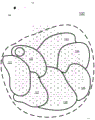
Fig. 1 is an illustration of a radio wave network 100 for implementing a UE-centric system access scheme in accordance with an embodiment of the present invention. In particular, the network 100 is used to implement DCS association of UEs to enable contention-free fast access and fast connection establishment of access events. For the access activities described below, these access events were previously achieved through a contention-based initial access setup procedure. In another aspect, embodiments of the present invention provide contention-free fast access and fast connection setup that may avoid initial entry into the setup procedure under various access activity scenarios, including but not limited to transitions from idle mode to active/connected mode, link failures and retries, bandwidth requests (e.g., for short packet transmissions), uplink resynchronization while the UE is in idle mode, and UE location updates while the UE is in idle mode.
As shown in fig. 1, wireless network 100 includes an area 110, wherein the area includes a plurality of transmission/reception points. At least one transmission/reception point (e.g., transmission/reception point 150) supports access of one or more UEs to radio wave network 100. For example, a representative transmit/receive point includes a base station that may be used to provide access to radio wave network 100 for one or more UEs that are within a signal range of the base station (e.g., station 155). By convention, representative transmit/receive points 150 are drawn as a hexagon, but other embodiments support other shapes of transmit/receive points. These UEs include both mobile and stationary devices that transmit and receive information (e.g., voice, data, etc.) with other devices via the communication network 100.
For example, a transmit/receive point in the radio wave network 100 may support one or more types of systems, such as systems that provide voice services, data services, messaging, or any other type of service. For example, wireless systems providing circuit-switched voice services include second generation wireless telephony (2G) systems, such as Code Division Multiple Access (CDMA) and GSM, and third generation telephony (3G), such as CDMA2000 and UMTS. In addition, systems that may provide data services include 2G, 3G, fourth generation telephony (4G), also known as Long Term Evolution (LTE), evolution-data optimized (EVDO), Wi-Fi, and so on. Other types of wireless systems are also contemplated, including UE-centric virtualized Radio Access Networks (RANs).
In some embodiments, wireless network 100 is a virtual RAN for implementing transmission point virtualization to increase wireless access capabilities. Through transmission point virtualization, the network may dynamically select one or more optimal transmission/reception points to serve a particular UE, where transmission point selection is transparent to the UE. For example, a transmitting/receiving point supports wireless access to a communication network. Embodiments of the present invention provide active, contention-free and fast access for UEs to a communication network by using dedicated connection signatures. In particular, embodiments provide active, contention-free and fast access to an access zone containing one or more transmission/reception points in order to access a communication network.
The area 110 is configured as one or more access zones. For example, as shown in fig. 1, the area 110 includes access zones 121 to 127. The at least one access area includes one or more transmission/reception points that provide access to the radio wave network 100 for one or more UEs located within the signal range. For purposes of illustration, the access area 121 includes a set of transmission/reception points. The other transmission/reception points may also include multiple sets of transmission/reception points. In this way, UEs moving throughout the area 110 can access the radio wave network 100 through any supported transmission/reception point in the area 110. For example, in a virtual RAN, a UE may be served by one or more transmit/receive points. Furthermore, the number of transmit/receive points serving the UE may vary over time, and the configuration of these transmit/receive points is transparent to the UE. In an embodiment of the present invention, a UE-centric DCS-based access scheme provides access to a communication network, in particular, to transmission/reception points in a corresponding access area (e.g., one of access areas 121-127), through one or more transmission/reception points in area 110.
The radio wave network 100 is configured to include a plurality of DCS that provide active access to one or more UEs within the area 110. By employing a large number of structurally sophisticated random DCS access sequences (e.g., Zadoff-Chu coding sequences, etc.) and intelligent coding and access management strategies, DCS assignments enable decoupling of UEs from transmit/receive points and fast connection establishment through virtual radio access networks. In particular, the UE is served by multiple transmission/reception points without separate cell identifiers.
In particular, the network 100 is configured to assign a first DCS to a first UE. The first DCS, as implemented by the first UE, provides the first UE with active access to one or more transmission/reception points within a first access zone (e.g., access zone 121). That is, the first UE is able to communicate with any transmission/reception point in the first access zone during an active connection using the first DCS. Thus, the first DCS provides the first UE with active access to the radio wave network through the first access zone.
Fig. 2A is an illustration of a control structure and/or hierarchy 200A for implementing a UE-centric system access scheme to a communication network in accordance with one embodiment of the present invention. For example, according to one embodiment of the invention, the control structure 200A may be used to control the distribution and management of DCS sequences that can provide UE-centric system access to the radio wave network of fig. 1.
As shown in fig. 2A, one or more transmit/receive points 210 provide wireless access to a wireless network, such as communication network 100 of fig. 1. For example, a transmit/receive point includes a base station that may be used to provide initial and active access to a radio wave network for one or more UEs. These transmit/receive points support signature sequence detection for initial access and unified/active access. In addition, each transmit/receive point maintains an active sequence set for the UEs it is serving and is likely to be serving. In addition, the transmitting/receiving point is used to support signal strength measurement on the uplink channel and report the measurement result to the higher layer control.
In one embodiment, the transmission/reception points are grouped in one or more access zones. The access zones are associated with one or more access zone control nodes 220. For example, at least one access zone is associated with a corresponding access zone control node. An access area control node enables and/or provides distribution and management of DCS used by UEs served by transmission/reception points in the access area. That is, the access zone control node 220 serves to manage all transmission/reception points in the access zone to ensure cooperation between the transmission/reception points. In particular, the access zone control node 220 implements contention free management of the DCS within its corresponding access zone. In addition, two or more access zone control nodes 220 cooperatively provide contention-free management of DCS between adjacent access zones. In addition, the access area control node provides assignment of serving transmit/receive points and optimization thereof for each UE based on uplink measurements associated with the UE. The access area control node 220 also maintains access profile for the UEs served by the transmit/receive points within the access area and informs each transmit/receive point of the profile of the UEs served within the access area to include a unified DCS sequence. Also, the access area control node 220 is able to monitor the mobility and positioning of UEs within the access area. The information is forwarded to the higher level nodes. Also, the access area control node 220 is used to assign DCS sequences to UEs during the initial access procedure, to assign active DCS sequences to UEs as directed by the network/regional control node, and to manage soft handover of DCS sequences between two access areas.
The network/regional control node 230 provides contention-free management of DCS used within a region. In particular, the network/area control node 230 manages the underlying access area control node 220. For example, the network/area control node 230 manages DCS sequence distribution to UEs using transmission/reception points throughout the area, as implemented by the middle control layer of the corresponding access area control node and the lower control layers of the respective transmission/reception points. For example, the network/area control node 230 may be used to assign DCS and UE pairs for use within the corresponding area. Additionally, the network/area control node 230 may be used to move at least one DCS between two access areas in an area to meet the increasing demand for DCS within the access area. That is, the network/area control node 230 is configured to dynamically coordinate DCS sequence allocations between two or more access zones based on DCS sequence allocations and reuse policies. In addition, the network/area control node 230 is used to monitor the mobility of the UEs in cooperation with the access zone control node 220 and to share the access profile of various UEs among various virtual access zones.
Fig. 2B is an illustration of a control node 200B of the control structure of fig. 2A, according to an embodiment of the present invention. In one embodiment, the control node is representative of the access area control node 220 in fig. 2A. In one embodiment, the control node is representative of the network/area control node 230 of fig. 2A.
In particular, the controlling node 200B comprises a DCS manager 210 for assigning and managing embodiments of intra-area DCS/UE pairs. For example, at the network/regional control node level, the control node 200B is configured to assign DCS groups to the access zone in a reuse pattern to maximize the use of multiple DCS. In addition, the control node 200B is configured to assign a DCS to a corresponding UE of the DCS/UE pair for use in the access zone. The implementation of the assignment is done at the access area control node level.
The controlling node 200B includes a UE manager 220 for tracking UEs served by transmission/reception points within a corresponding access area and/or region. For example, the UE manager 220 can obtain and store location information and other identification information (e.g., DCS assignments, device identifiers, etc.) for the corresponding UE. In one embodiment, the location information is obtained by triangulation of received signal strength at one or more transmit/receive points within the signal range of the corresponding UE. In one embodiment, the control and management of UE-related information is performed at a network/regional control node to implement contention-free management of DCS/UE pairs throughout the region. In another embodiment, UE-related information control and management is performed at an access area control node, in one case to implement contention-free management of DCS/UE pairs at an area layer managed by an overlay network/area control node, and in another case to implement contention-free management of DCS UE pairs at an access area layer managed by a corresponding access area control node.
The controlling node 200B also includes a soft handover manager 230 for coordinating DCS assigned handovers as the UE moves from one access area to another. There is a soft handoff manager 230 at both the access area control node and the network/area control node. Thus, the soft handover manager 230 at both layers is able to communicate and cooperate to provide DCS sequence handovers for a particular UE to seamlessly access a transmission/reception point in the area between the two access areas.
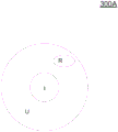
Fig. 3A is a diagram 300A of distribution of a Dedicated Connection Signature (DCS) throughout an area including a plurality of transmission/reception points providing access to a radio wave network, in accordance with one embodiment of the present invention. The multiple DCS sequences are divided into three non-overlapping sets: a set { I } for performing initial access; a set { U } for performing active connection access, and a set { R } as a reservation sequence. In one embodiment, after authorization is completed through the initial access procedure, each UE/device is assigned a unique DCS sequence in the set { U }.
As previously described, once assigned in a DCS/UE pair, the DCS provides UE-centric active access to the radio wave communication network. In particular, DCS provides connectivity to transmission/reception points within an access area that is always connected or active even when the UE is in idle mode. That is, the DCS is always active and always associated with the UE until further reassignment. This further reduces signaling overhead because the air link does not need to perform an initial access connection when performing the previously described access event (e.g., uplink resynchronization, transition from idle mode to active mode, etc.).
Fig. 3B is an illustration of DCS distribution in which the DCS provides active access to the radio wave network to mobile and static UEs in accordance with one embodiment of the invention. As shown in fig. 3B, the set { U-mobile } includes DCS sequences assigned to the mobile UE. Further, the set { U-static } includes DCS sequences assigned to static UEs (e.g., smart meters, etc.).
Turning now to fig. 3C, a table 300 illustrates an increase in available DCS as the available geographic area of transmit/receive points decreases, which is a current and future deployment trend for wireless cellular networks, in accordance with one embodiment of the present invention. In particular, table 300C illustrates the use of a large number of DCS sequences throughout an area, particularly as the size of the service area of a transmission/reception point decreases, where the area includes one or more access zones comprised of one or more transmission/reception points.
Specifically, assuming a sequence length of 839 bits, service areas (in terms of radius) of two sizes of transmission/reception points are given. The first service area size is approximately 13 kilometers (km) consistent with the service area size used in current cellular network deployments, while the second service area size is approximately 5km, simulating current and future cellular network deployments. That is, the first service area size supports a distance of up to 13km between the UE and the base station supporting the transmission/reception point, while the second service area size is smaller because it is used to support a distance of up to 5km between the UE and the corresponding base station.
For example, as shown in table 300C, when implementing the Zadoff-Chu sequence pattern to determine a set of random DCS access sequences, the service areas of the two sizes of transmission/reception points provide zero cross-correlation between two DCS sequences of the same root node at the receiver and the best cross-correlation (e.g., 0.0345) between any two DCS sequences of different root nodes. Both scenarios provide contention-free DCS access to the radio wave network. However, by reducing the serving cell size of the transmit/receive point, the number of available sequences will increase. For example, in a service area size of 13km, performing cyclic shift in one sequence of 13 yields approximately 53000 DCS sequences. By reducing the service area size to 5km, a cyclic shift of 5 can be implemented, which results in about 140000 DCS sequences available in the area. There is also an increase in this set of DCS sequences, with sequence lengths 421 or 211.
In an embodiment, multiple DCS are divided into DCS for static UEs/devices and for mobile UEs/devices to implement differentiated policies for implementing intelligent coding and access management. For example, in one embodiment, for a set of static UEs { U-static }, a code reuse strategy is implemented over the entire area of the access region to maximize code reuse efficiency. For static UEs, the code reuse policy is not access specific. In this way, this minimizes the set of DCS sequences for static devices { U-static }. This, in turn, makes more DCS sequences available for the mobile UE in the set U-mobile.
In one embodiment, fig. 4 is a DCS distribution 400 illustrating static UEs throughout an area including a plurality of transmission/reception points providing access to a radio wave communication network. The distribution 400 maximizes the code reuse efficiency to minimize the number of DCS sequences in the set U-static. In particular, the distribution 400 depends on the spacing of the minimum distance (D-min) of the DCS sequence used by the static UE. That is, two UEs may be assigned the same DCS sequence as long as one UE is D-min away from the other UE.
In the example provided above, the two UEs may be identified by their respective locations. That is, the UE is identified by a unique identifier that contains the DCS and the geographical location of the UE. For example, the location of the UE is determined by triangulation of two or more signals, including measuring the strength of the uplink channel strength signal to determine the distance from the measuring transmission/reception point. That is, by triangulation, the geographical location of the UE is determined based on uplink channel strength measurements of at least two base stations corresponding to two transmit/receive points.
In fig. 4, UEs W, X, Y, and Z are located in an area containing a plurality of transmission/reception points providing radio wave access to a communication network. The DCS sequence is assigned based on the D-min strategy outlined above. For example, UE W is assigned a DCS sequence S-12 to form a UE/DCS pair that is uniquely identifiable by its DCS sequence and UE location. Other UE/DCS pairs include X/S-13, Y/S-11, and Z/S-13. All UE/DCS pairs co-exist because there is no overlap between geographical areas (e.g., as defined by D-min) between UEs. In this way, UE X and Z are assigned the same DCS (S-13) because they are at least a distance of D-min apart.
On the other hand, for the set of mobile UEs { U-mobile }, different strategies are implemented to maximize the geographic footprint of the access area used throughout the area. In addition, the number of available DCS sequences is maximized, while the number of reuse factors is minimized. These are all used to reduce the need for soft handover of DCS sequences near the border of the two access zones.
For example, fig. 5 is a diagram illustrating a reuse pattern of DCS sequences throughout an area, which is implemented in an efficient UE-centric unified system access scheme based on reducing DCS handover of a UE between two access areas, according to one embodiment of the invention. The core of this code reuse strategy is to maximize the size of the access zones in the area, as implemented for mobile UEs in reuse pattern 500, where area 500 includes multiple access zones. In addition, the DCS sequence pool is increased as much as possible (e.g., supporting a reduced service area size of transmission/reception points, increasing access sequence length, etc.), and the reuse factor is reduced to as small as possible by optimizing access partitioning. This strategy provides reliable soft handoff of the DCS sequence by using a mobile grace zone as will be further described in fig. 6. In addition, the strategy is further enhanced by dynamic sequence modulation between two or more access zones.
By way of example, fig. 5 shows an area 500 containing six access zones 510, 520, 530, 540, 550, and 560. Region 500 is associated with a plurality of DCS sequences divided by a reuse factor. For example, the reuse factor shown in fig. 5 is 3, which results in one possible distribution pattern 500. Thus, the multiple DCS sequences are divided into three groups: s-1, S-2 and S-3. This mode is used to provide contention free access for DCS/UE pairs that may operate between two adjacent access zones. As an example, group S-1 is assigned to access zones 530 and 560. Since the transmission/reception points in the two access zones 530 and 560, or more specifically the service areas in these transmission/reception points, do not overlap in the same geographical area, two UEs (e.g., one in the access zone 530 and one in the access zone 560) using DCS sequences associated with group S-1 but served by different transmission/reception points may be contention free to access the radio wave communication network. In addition, group S-2 is assigned to access zones 510 and 550 that have no overlapping zones. In addition, group S-3 is assigned to access zones 520 and 540 that have no overlapping zones. Furthermore, the size of the access zone is determined by the number of DCS sequences available for the area, the reuse factor, and the UE density within the entire area.
Fig. 6 is a diagram 600 illustrating a mobility grace region 630 for implementing DCS soft handover when a UE moves from one access region to another access region, according to one embodiment of the present invention. The distribution and configuration of access zones shown in diagram 600 maximizes the geographic footprint of each access zone used throughout the area to reduce instances of DCS sequence soft handoff of the boundary of two access zones.
Specifically, the diagram 600 includes two access zones 610 and 620, where the size of the access zones is maximized to reduce soft handoff scenarios, according to various factors listed above. Access zone 610 is assigned to a first set of DCS sequences, S-1; the access region 620 is assigned to a second set of DCS sequences, S-2, where the DCS sequences in sets S-1 and S-2 do not overlap to provide contention free access to the communication network for the DCS/UE pair. Further, access zone 610 is adjacent to access zone 620 and shares boundary 615.
A mobility grace region 630 is included to provide reliable soft handover of the DCS sequence as the UE moves between the two access regions 610 and 620. Specifically, the mobility grace region 630 is located at the boundary 615 between the two access regions 610 and 620 and provides generic access to DCS sequences in the access regions 610 and 620. That is, the transmission/reception point within the mobility grace region 630 is able to provide active access to the underlying radio wave communication network for any DCS/UE pair associated with one of the access regions 610 and 620. In this way, the mobility grace region 630 acts as a neutral region, where the DCS/UE pair can operate without switching DCS sequences. This greatly reduces the "ping-pong" hysteresis effect that occurs each time the UE switches over a boundary from one DCS associated with one access area to another DCS associated with another access area.
In addition, the mobility grace region 630 facilitates reliable soft handoff when a corresponding UE is determined to be already within the boundary of a new access region and has left the old access region. In this case, upon determination, a handover to a new DCS associated with the new access area is assigned to the corresponding UE, and the UE continues to communicate with the radio wave network using the new DCS. For example, FIG. 6 illustrates movement of a UE device along a path 650 from a first location at a point 651 associated with time t-1 to a second location at a point 659 associated with time t-2. As the UE device moves within mobility grace region 630, the UE device maintains its old DCS sequence assigned by the access region control node associated with access 610, even after crossing access region boundary 615 and accessing the network using the transmit/receive points in access region 620. When it is determined that the UE has completely left the access zone 610 (e.g., at point 655 on path 650), a new DCS from the set of DCS sequences for the access zone 620 is assigned to the UE.
In one embodiment, management of DCS sequences between different access zones allows for dynamic sequence adjustment between two or more access zones. For example, one or more control nodes (e.g., access zone control nodes and/or network/area control points) can determine when a large number of UEs will move to or be present in a given access zone. To accommodate the increased number of UEs, DCS sequences in underutilized access areas may be temporarily dynamically transferred for use within the overutilized access area. For example, a first set of DCS sequences is assigned to a first access zone and a second set of DCS sequences is assigned to a second access zone. Dynamic code sharing allows DCS sequences originally assigned to a first group serving a first access zone to be reassigned to a second group for use within a second access zone.
Fig. 7 is a flow diagram 700 illustrating a method for configuring a network, in particular, for providing system access for a plurality of UEs to a radio wave communication network, in accordance with one embodiment of the present invention. In one embodiment, the method outlined in diagram 700 may be implemented in the network 100 shown in fig. 1 to provide system access using a DCS sequence.
In step 710, the method includes configuring a plurality of transmission/reception points providing radio wave access in at least one access area. Providing the plurality of transmission/reception points in an area, wherein the area comprises one or more access zones, and wherein at least one access zone comprises one or more transmission/reception points. On a basic level, at least one transmitting/receiving point comprises a base station supporting radio wave access to a communication network.
In step 720, the method includes providing a plurality of DCS sequences for use in providing active access to a communication network for a plurality of UEs. After the UE authorizes the network through the initial access procedure, the DCS sequence is assigned in the DCS/UE pair. Upon authorization, the UE is assigned a DCS to actively access the communication network in any of a series of access events, including, in part, uplink resynchronization, transitions from idle mode to active mode (e.g., for reconnecting the UE to the wireless network through supported transmit/receive points in the access area when the UE comes out of idle mode), virtual handoffs (e.g., between different radio access technologies), link failures and retries, UE location updates (e.g., during idle mode), and for sending communications (e.g., bandwidth requests for short packet transmissions) between transmit/receive points in the access area and the UE.
In step 730, the method includes configuring a first set of DCS sequences, including one or more DCS sequences of the plurality of DCS. The DCS sequences in the first group provide active access to the transmission/reception points in the first access zone. In particular, the DCS sequence is associated with one or more of the plurality of UEs. That is, the DCS/UE pair provides a UE-centric model, where the corresponding DCS allows active access by the UE to the transmit/receive points within the first access zone.
In another embodiment, the DCS sequences are configured in one or more sets of DCS. The groups are formed according to a reuse factor, wherein a set of DCS sequences may be assigned to one or more access zones. In particular, the set of DCS sequences is assigned to an access area in a mode that facilitates contention-free access to a radio wave communication network between transmission/reception points of two adjacent access areas. For example, the reuse pattern 500 of DCS sequences described above in relation to fig. 5 is formed according to a reuse factor of 3 to reduce the instances of soft handover of DCS sequences between two access zones.
Fig. 8 is a flow chart 800 illustrating a method of providing a UE with system access to a radio wave communication network in accordance with one embodiment of the present invention. In another embodiment, the flowchart 800 is implemented in a computer system including a processor and a memory coupled to the processor, the computer system having stored therein instructions that, if executed by the computer, cause the system to perform a method of program execution capable of providing a UE with system access to a radio wave communication network. In another embodiment, instructions to perform a method are stored on a non-transitory computer-readable storage medium having computer-executable instructions to cause a computer system to perform a method for program execution that is capable of providing a UE with system access to a radio wave communication network. The method outlined in flowchart 800 may be implemented by one or more components of the system as well as device 200B and computer system 1000 in FIG. 2B and FIG. 10.
In step 810, the method includes authenticating the UE with the corresponding transmission/reception point upon initial entry into the communication network. The communication network comprises a plurality of transmission/reception points, one of which comprises a base station supporting radio wave access for one or more UEs to said communication network.
In step 820, the method includes assigning a DCS to the UE as a DCS/UE pair. In particular, the DCS provides the UE with active access to a transmission/reception point that provides radio wave access to a communication network. At least one of the transmission/reception points comprises a base station providing radio wave access.
In one embodiment, the DCS provides the UE with active access to the transmission/reception points of packets into the access zone. For example, the method includes configuring a plurality of DCS sequences in one or more groups based on a reuse factor. A set of DCS sequences may be assigned to one or more access zones, wherein one or more transmission/reception points in at least one access zone provide radio wave access to a communication network. The groups are assigned to the access areas in a mode that facilitates contention-free access to DCS/UE pairs between at least two transmission/reception points in adjacent access areas.
Fig. 9A is a diagram illustrating a dynamic distance sensing scheme for assigning DCS/UE pairs within the area of a transmission/reception point 910 that provides wireless access to a communication network, in accordance with one embodiment of the present invention. A unified system access scheme centered on UEs provides a mobile UE with DCS allocation and DCS code reuse strategies, which assigns DCS sequences to the UE according to a distance interval (D-min). The maximized reuse distance (e.g., D-min) is based on the available number of DCS sequences and the UE density. Specifically, after a check determines that no other UE has been assigned the same DCS sequence within a minimum distance (D-min), the DCS sequence S-13 is assigned to the UE ("Z"). Accordingly, the DCS sequence S-13 is also assigned to another UE labeled "X" because the separation between the positions of these two UEs ("X" and "Z") is at least greater than D-min.
In an embodiment, a central node is used to monitor location and DCS/UE pair assignments. That is, the UE identifier includes the DCS sequence and location information of the corresponding UE. That is, only one level of operating system control is required at the network/regional control node level. Therefore, the access zone is not used in the dynamic distance sensing scheme.
In addition, the mobile UEs may be further classified based on different mobility levels. Different mobility levels are associated with different reuse distance thresholds (D-min). For example, mobile UEs may be classified into slow or fast categories. The D-min for those UEs classified as slow may be less than the D-min for UEs classified as fast. Other categories for distinguishing between UEs are considered and supported in other embodiments.
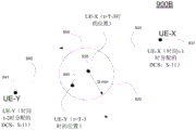
Fig. 9B is a diagram 900B illustrating the movement of two UE devices assigned the same DCS and various schemes for implementing contention free access to a radio wave network, in accordance with one embodiment of the present invention. Fig. 9B shows an embodiment of the dynamic distance sensing scheme first shown in fig. 9A, so in one embodiment only one control node is needed for DCS/UE pair management.
For example, diagram 900B shows movement of UE-X along path 930 and movement of UE-Y along path 940. At point 931, at time t-1, a control node (not shown) assigns a DCS sequence (DCS S-11) to UE-X for use in accessing the wireless communication network. Further, at point 941, at time t-2, the control node also assigns DCS S-11 to UE-Y for use in accessing the wireless communication network. The two UEs are separated by a distance (e.g., by at least D-min) such that there is contention free access to the communication network.
However, at time t-3, UE-X is located at point 935 on path 930 and UE-Y is located at point 945 on path 940. Further, the distance between the two UEs is less than D-min. That is, UE-Y is located in area 950 defined by the location of UE-X at point 935 and D-min. The control node is capable of monitoring the movement of either or both of the two UEs to provide contention-free access to the wireless communication network.
In an embodiment, the control node is able to reassign the DCS that UE-Y used at or before point 945 on path 940. That is, when it is determined that any two UEs are within a certain range (e.g., the range may be greater than, less than, or equal to D-min) and are close to each other, the control node provides a soft handover of the DCS sequence. Thus, since UE-Y is now assigned to the new DCS, the DCS sequence S-11 used by UE-X at point 935 is able to provide contention-free access to the communication network because there are no other UEs within the D-min region 950 that use the same DCS.
In another embodiment, a zero switching scheme is provided. In particular, when the control node determines that any two UEs are within a certain range (e.g., the range may be greater than, less than, or equal to D-min) and are close to each other, multiplexing of DCS sequences is implemented to provide contention-free access to the radio wave communication network. For example, frequency or time multiplexing (using different subframes) may be implemented to provide contention-free access to the communication network.
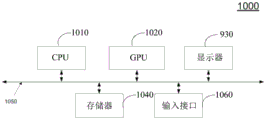
FIG. 10 is a block diagram of an example of a computing system 1000 capable of implementing embodiments of the present invention. Computing system 1000 broadly represents any single or multi-processor computing device or system capable of executing computer-readable instructions. Examples of computing system 1000 include, but are not limited to, workstations, laptops, client-side terminals, servers, distributed computing systems, handheld devices, or any other computing system or device. In its most basic configuration, computing system 1000 may include at least one processor 1010 and a system memory 1040.
Both Central Processing Unit (CPU)1010 and Graphics Processing Unit (GPU)1020 are coupled to memory 1040. System memory 1040 generally represents any type or form of volatile or non-volatile storage device or medium capable of storing data and/or other computer-readable instructions. Examples of system memory 1040 include, but are not limited to, RAM, ROM, flash memory, or any other suitable memory device. In the example of fig. 10, the memory 1040 is a shared memory, and thus the memory stores instructions and data for both the CPU1010 and the GPU 1020. Alternatively, there may be separate memories dedicated to the CPU1010 and GPU1020, respectively. The memory may include a frame buffer for storing pixel data that drives the display screen 1030.
Computing system 1000 includes a user interface 1060 that, in one embodiment, includes a screen cursor control device. The user interface may include a keyboard, a mouse, and/or a touch screen device (touchpad).
CPU1010 and/or GPU1020 generally represent any type or form of processing unit capable of processing data or parsing and executing instructions. In certain embodiments, the processors 1010 and/or 1020 may receive instructions from a software application or a hardware module. These instructions may cause processors 1010 and/or 1020 to perform the functions of one or more of the example embodiments described and/or illustrated herein. For example, the processors 1010 and/or 1020, alone or in combination with other elements, may perform and/or be a means for performing one or more of the monitoring, determining, controlling, detecting, etc., described herein. Processors 1010 and/or 1020 may also perform and/or be a means for performing any other steps, methods, or procedures described and/or illustrated herein.
In some embodiments, a computer readable medium containing a computer program may be loaded into computing system 1000. All or a portion of the computer program stored on the computer-readable medium may then be stored in the system memory 1040 and/or various portions of the storage device. When executed by the processors 1010 and/or 1020, a computer program loaded into the wireless communication device 1000 may cause the processors 1010 and/or 1020 to perform and/or be a means for performing the functions of the example embodiments described and/or illustrated herein. Additionally or alternatively, the example embodiments described and/or illustrated herein may be implemented in firmware and/or hardware.
Embodiments of the present invention may be implemented using hardware only or using software and an essentially general-purpose hardware platform. Based on this understanding, the technical solution of the present invention can be embodied in the form of a software product. The software product comprises a plurality of instructions for causing a computer device (personal computer, server or network device) to perform the method provided in an embodiment of the invention.
The embodiments described herein are discussed in the general context of computer-executable instructions, which may be located in some form of computer-readable medium, such as program modules, and executed by one or more computers or other devices. By way of example, and not limitation, the software product may be stored in non-volatile or non-transitory computer-readable storage media, which may include non-transitory computer storage media and communication media. Generally, program modules include routines, programs, objects, components, data structures, etc. that perform particular tasks or implement particular abstract data types. The functionality of the program modules may be combined or separated as desired in various embodiments.
Computer storage media includes volatile and nonvolatile, removable and non-removable media implemented in any method or technology for storage of information such as computer readable instructions, data structures, program modules or other data. Computer storage media includes, but is not limited to, Random Access Memory (RAM), Read Only Memory (ROM), electrically erasable programmable ROM (eeprom), flash memory or other memory technology, compact disc read only memory (CD-ROM), USB flash disk, Digital Versatile Disk (DVD) or other optical storage, magnetic cassettes, magnetic tape, removable hard disks, magnetic disk storage or other magnetic storage devices, or any other medium which can be used to store the desired information and which can be accessed to retrieve the information.
Communication media may embody computer-executable instructions, data structures, and program modules and include any information delivery media. By way of example, and not limitation, communication media includes wired media such as a wired network or direct-wired connection, and wireless media such as acoustic, radio, infrared and other wireless media. Combinations of any of the above should also be included within the scope of computer readable media.
Thus, the apparatus and methods described by embodiments of the present disclosure illustrate the implementation of a UE-centric approach for accessing a virtual wireless access network. Embodiments of the present invention provide DCS/UE pair assignments that allow for fast connection establishment towards a UE in an always connected manner throughout an area that includes one or more transmission/reception points for wireless access to a communication network. In other embodiments, the UE-centric approach can reduce signaling overhead because no control signaling is required to move from one transmit/receive point to another because both transmit/receive points consider the DCS/UE pair to provide active access to the radio wave communications network.
Although the foregoing disclosure sets forth various embodiments using specific block diagrams, flowcharts, and examples, each block diagram component, flowchart step, operation, and/or component described and/or illustrated herein may be implemented, individually and/or collectively, by a variety of hardware, software, or firmware (or any combination thereof) configurations. In addition, the disclosure of any component included among other components should be taken as an example, as many other architectures can be implemented to achieve the same functionality.
The process parameters and the order of the steps described and/or illustrated herein are for example only and may be altered as desired. For example, while the steps illustrated and/or described herein may be shown or discussed in a particular order, these steps need not be performed in the order illustrated or discussed. Various example methods described and/or illustrated herein may also omit one or more steps described and/or illustrated herein or may also include additional steps in addition to those disclosed.
Although various embodiments have been described and/or illustrated herein in the context of fully functional computing systems, one or more of these exemplary embodiments may be distributed as a program product in a variety of ways, regardless of the particular form of computer-readable media used to actually carry out the distribution. Embodiments disclosed herein may also be implemented using software modules that perform some specific tasks. These software modules may include scripts, batches or other executable files, which may be stored on a computer readable medium or in a computer system. The software modules may configure a computer system for performing one or more of the example embodiments disclosed herein. One or more software modules disclosed herein may be implemented in a cloud computing environment. Cloud computing environments may provide different services and applications over the internet. These cloud-based services (e.g., software as a service, platform as a service, infrastructure as a service, etc.) may be accessed through a web browser or other remote interface. The various functions described herein may be provided through a remote desktop environment or any other cloud-based computing environment.
Although the present invention and its advantages have been described in detail, it should be understood that various changes, substitutions and alterations can be made herein without departing from the spirit and scope of the invention as defined by the appended claims. Many modifications and variations are possible in light of the above teaching. The embodiments were chosen and described in order to best explain the principles of the invention and its practical applications, to thereby enable others skilled in the art to best utilize the invention and various embodiments with various modifications as are suited to the particular use contemplated.
Moreover, the scope of the present disclosure is not intended to be limited to the particular embodiments of the process, machine, manufacture, composition of matter, means, methods and steps described in the specification. As one of ordinary skill in the art will readily appreciate from the disclosure, processes, machines, manufacture, compositions of matter, means, methods, or steps, presently existing or later to be developed that perform substantially the same function or achieve substantially the same result as the corresponding embodiments described herein may be utilized according to the present disclosure. Accordingly, the appended claims are intended to include within their scope such processes, machines, manufacture, compositions of matter, means, methods, or steps.
Embodiments in accordance with the invention are described herein. While the present invention has been described in particular embodiments, it should be appreciated that the present invention should not be construed as limited by such embodiments, but rather construed according to the below claims.