CN109693757B - Bicycle stepless automatic transmission - Google Patents
Bicycle stepless automatic transmission Download PDFInfo
- Publication number
- CN109693757B CN109693757B CN201710992885.1A CN201710992885A CN109693757B CN 109693757 B CN109693757 B CN 109693757B CN 201710992885 A CN201710992885 A CN 201710992885A CN 109693757 B CN109693757 B CN 109693757B
- Authority
- CN
- China
- Prior art keywords
- disc
- power output
- rotors
- displacement plate
- power input
- Prior art date
- Legal status (The legal status is an assumption and is not a legal conclusion. Google has not performed a legal analysis and makes no representation as to the accuracy of the status listed.)
- Expired - Fee Related
Links
- 230000005540 biological transmission Effects 0.000 title claims abstract description 49
- 230000009467 reduction Effects 0.000 claims abstract description 16
- 238000006073 displacement reaction Methods 0.000 claims description 64
- 230000006835 compression Effects 0.000 claims description 3
- 238000007906 compression Methods 0.000 claims description 3
- 230000002093 peripheral effect Effects 0.000 claims description 3
- 230000008859 change Effects 0.000 abstract description 10
- 230000009471 action Effects 0.000 abstract description 2
- 230000000694 effects Effects 0.000 description 3
- 238000012986 modification Methods 0.000 description 3
- 230000004048 modification Effects 0.000 description 3
- 230000007423 decrease Effects 0.000 description 2
- 238000010586 diagram Methods 0.000 description 2
- 230000001133 acceleration Effects 0.000 description 1
- 230000008901 benefit Effects 0.000 description 1
- 238000006243 chemical reaction Methods 0.000 description 1
- 230000007812 deficiency Effects 0.000 description 1
- 238000000034 method Methods 0.000 description 1
Images


Classifications
-
- B—PERFORMING OPERATIONS; TRANSPORTING
- B62—LAND VEHICLES FOR TRAVELLING OTHERWISE THAN ON RAILS
- B62M—RIDER PROPULSION OF WHEELED VEHICLES OR SLEDGES; POWERED PROPULSION OF SLEDGES OR SINGLE-TRACK CYCLES; TRANSMISSIONS SPECIALLY ADAPTED FOR SUCH VEHICLES
- B62M11/00—Transmissions characterised by the use of interengaging toothed wheels or frictionally-engaging wheels
- B62M11/04—Transmissions characterised by the use of interengaging toothed wheels or frictionally-engaging wheels of changeable ratio
- B62M11/14—Transmissions characterised by the use of interengaging toothed wheels or frictionally-engaging wheels of changeable ratio with planetary gears
Landscapes
- Engineering & Computer Science (AREA)
- Chemical & Material Sciences (AREA)
- Combustion & Propulsion (AREA)
- Transportation (AREA)
- Mechanical Engineering (AREA)
- Transmission Devices (AREA)
- Friction Gearing (AREA)
Abstract
本发明是自行车无段自动变速装置,其包含一壳体、一中心轴、一动力输入碟、一动力输出碟、两转子、两传动碟、一离心组件、一弹性元件及一逆转组件,离心组件连接及带动两转子,当自行车车轮转速越高时,离心组件的转速也会越高,而离心组件在离心力的作用下会自动转动两转子来逐渐降低动力输入碟及动力输出碟的减速比;而当车轮转速降低时,弹性元件会推动离心组件以反向转动该两转子,以提升动力输入碟及动力输出碟的减速比;本发明借此通过车轮转动时产生的离心力来自动控制转子的转动并进而自动调整减速比,以达到自动无段变速的发明目的。

The present invention is a stepless automatic speed change device for a bicycle, which comprises a housing, a central axis, a power input disc, a power output disc, two rotors, two transmission discs, a centrifugal assembly, an elastic element and a reversing assembly. The centrifugal assembly connects and drives the two rotors. When the rotation speed of the bicycle wheel is higher, the rotation speed of the centrifugal assembly will also be higher. Under the action of centrifugal force, the centrifugal assembly will automatically rotate the two rotors to gradually reduce the reduction ratio of the power input disc and the power output disc. When the wheel rotation speed is reduced, the elastic element will push the centrifugal assembly to reversely rotate the two rotors to increase the reduction ratio of the power input disc and the power output disc. The present invention automatically controls the rotation of the rotor and then automatically adjusts the reduction ratio through the centrifugal force generated when the wheel rotates, so as to achieve the invention purpose of automatic stepless speed change.
Description
技术领域technical field
本发明涉及一种自行车的变速装置,尤指一种利用EXTROID CVT的自动无段变速装置。The invention relates to a speed change device of a bicycle, in particular to an automatic stepless speed change device using EXTROID CVT.
背景技术Background technique
EXTROID变速器(EXTROID CVT)是一种常见于汽车或自行车等交通工具的无段变速装置,其包含有一动力输入碟、一动力输出碟、两转子及两传动碟;动力输入碟及动力输出碟相互间隔且同轴心地设置,动力输入碟及动力输出碟朝向彼此分别突出有一圆锥部,两转子位于动力输入碟及动力输出碟之间,两传动碟分别可转动地设于两该转子上,各传动碟的相对两侧分别贴靠于动力输入碟及动力输出碟的圆锥面,借此当动力输入碟转动时,动力输入碟带动传动碟转动,而传动碟再带动动力输出碟转动;而通过让传动碟的两侧贴靠于动力输入碟及动力输出碟的圆锥面的不同位置处,便可达到加速或减速的功效角度;而欲改变转速比时,仅要转动转子便可改变传动碟的角度,进而改变传动碟的两侧贴靠于动力输入碟及动力输出碟的圆锥面的位置,如此便可改变转速比。EXTROID CVT (EXTROID CVT) is a stepless speed change device commonly used in vehicles such as automobiles or bicycles. It includes a power input disc, a power output disc, two rotors and two transmission discs; the power input disc and the power output disc are mutually Spaced and coaxially arranged, the power input disc and the power output disc respectively protrude toward each other with a conical portion, the two rotors are located between the power input disc and the power output disc, the two transmission discs are respectively rotatably arranged on the two rotors, each The opposite sides of the drive disc are respectively abutted on the conical surfaces of the power input disc and the power output disc, whereby when the power input disc rotates, the power input disc drives the drive disc to rotate, and the drive disc drives the power output disc to rotate; By making the two sides of the transmission disc abut against the different positions of the conical surfaces of the power input disc and the power output disc, the effect angle of acceleration or deceleration can be achieved; and when the speed ratio is to be changed, the transmission disc can be changed only by rotating the rotor. , and then change the position of the two sides of the transmission disc against the conical surfaces of the power input disc and the power output disc, so that the speed ratio can be changed.
然而,现有技术的EXTROID CVT欲改变转子来调整转速比时,通过手动操作的方式来转动该两转子,而无法达到自动变换的功效,如此在操作上有所不便,因此仍有待加以改进。However, when the prior art EXTROID CVT wants to change the rotors to adjust the speed ratio, the two rotors are manually operated to rotate the two rotors, and the effect of automatic conversion cannot be achieved, which is inconvenient in operation, and therefore still needs to be improved.
发明内容SUMMARY OF THE INVENTION
有鉴于前述的现有技术的缺点及不足,本发明提供一种自行车无段自动变速装置,以可在EXTROID CVT的架构上达到自动变速的目的。In view of the above-mentioned shortcomings and deficiencies of the prior art, the present invention provides a stepless automatic transmission device for bicycles, so as to achieve the purpose of automatic transmission in the framework of the EXTROID CVT.
为达到上述的发明目的,本发明所采用的技术手段为设计一种自行车无段自动变速装置,其中包含:In order to achieve the above-mentioned purpose of the invention, the technical means adopted in the present invention is to design a bicycle stepless automatic transmission device, which includes:
一壳体;a shell;
一中心轴,其贯穿该壳体;a central axis that penetrates the housing;
一动力输入碟,其能转动地设于该壳体内,且能转动地套设于该中心轴外,该动力输入碟的一侧面突出有一圆锥部;a power input disc, which is rotatably arranged in the casing and rotatably sleeved outside the central shaft, and a conical portion protrudes from one side of the power input disc;
一动力输出碟,其能转动地设于该壳体内,且能转动地套设于该中心轴外,该动力输出碟的一侧面突出有一圆锥部,该动力输入碟的圆锥部及该动力输出碟的圆锥部相向设置;A power output disc is rotatably installed in the casing and rotatably sleeved outside the central shaft. A conical portion protrudes from one side of the power output disc. The conical portion of the power input disc and the power output disc The conical parts of the dish are arranged opposite to each other;
两转子,其能转动地设于该壳体内,且各该转子与该壳体之间的枢转轴与该中心轴相互垂直;two rotors, which are rotatably arranged in the casing, and the pivot axis between each rotor and the casing is perpendicular to the central axis;
两传动碟,其分别能转动地设于两该转子上,且各该传动碟与该转子之间的枢转轴与该转子与该壳体之间的该枢转轴相互垂直;各该传动碟的相对两侧分别贴靠于该动力输入碟的圆锥部及该动力输出碟的圆锥部;当该动力输入碟转动时,该动力输入碟通过该传动碟转动该动力输出碟;Two transmission discs, which are respectively rotatably arranged on the two rotors, and the pivot shaft between the transmission disc and the rotor and the pivot shaft between the rotor and the housing are perpendicular to each other; The opposite sides are respectively abutted against the conical portion of the power input disc and the conical portion of the power output disc; when the power input disc rotates, the power input disc rotates the power output disc through the transmission disc;
一离心组件,其套设于该中心轴外,且连接及带动该两转子,当该离心组件相对该中心轴转动时,该离心组件会带动两该转子转动以降低该动力输入碟及该动力输出碟的减速比;A centrifugal assembly is sleeved outside the central shaft and connects and drives the two rotors. When the centrifugal assembly rotates relative to the central shaft, the centrifugal assembly drives the two rotors to rotate to reduce the power input disc and the power The reduction ratio of the output disc;
一弹性元件,其连接及推动该离心组件,并使该离心组件带动两该转子转动以提升该动力输入碟及该动力输出碟的减速比;an elastic element, which connects and pushes the centrifugal assembly, and makes the centrifugal assembly drive the two rotors to rotate to increase the reduction ratio of the power input disc and the power output disc;
一逆转组件,其连接于该动力输入碟或该动力输出碟,该逆转组件能将输入于该逆转组件的转动转换成相反方向的转动后再输出。A reversing component is connected to the power input disc or the power output disc, and the reversing component can convert the rotation input to the reversing component into the rotation in the opposite direction before outputting.
本发明的优点在于,通过进一步设置一离心组件来连接两该转子,借此当自行车的车轮转速越高时,离心组件相对中心轴的转速也会越高,而离心组件会自动转动两该转子来逐渐降低减速比,如此一来使用者踩踏踏板所需的力逐渐增加,而车轮转速也会逐渐增快;而当车轮转速降低时,弹性元件会推动离心组件以反向转动两该转子,使两该转子逆向转动以提升动力输入碟及动力输出碟的减速比,如此一来在车轮转速低甚至刚起步时,使用者仅需轻松地踩踏踏板便可带动车轮转动;本发明借此通过车轮转动时产生的离心力来自动控制转子的转动并进而自动调整减速比,借此达到自动无段变速的发明目的。The advantage of the present invention is that by further disposing a centrifugal assembly to connect the two rotors, when the speed of the wheel of the bicycle is higher, the rotation speed of the centrifugal assembly relative to the central shaft will also be higher, and the centrifugal assembly will automatically rotate the two rotors to gradually reduce the reduction ratio, so that the force required by the user to step on the pedal gradually increases, and the wheel speed gradually increases; and when the wheel speed decreases, the elastic element will push the centrifugal assembly to rotate the two rotors in the opposite direction. The two rotors are rotated in the opposite direction to increase the reduction ratio of the power input disc and the power output disc, so that when the wheel speed is low or even just starting, the user only needs to easily step on the pedal to drive the wheel to rotate; The centrifugal force generated when the wheel rotates automatically controls the rotation of the rotor and then automatically adjusts the reduction ratio, thereby achieving the invention purpose of automatic stepless speed change.
进一步而言,所述的自行车无段自动变速装置,其中该离心组件包含有一位移盘、多个滚柱及一连动臂;该位移盘能转动地套设于该中心轴外,且能沿该中心轴移动,该位移盘被该动力输入碟或该动力输出碟带动而转动,该位移盘的一侧面凹设成形有一圆锥状的容置空间,圆锥状的该容置空间以该中心轴的位置为中心;圆锥状的该容置空间的内壁面上设有多条径向轨道,多条所述径向轨道于该圆锥状的该内壁面上以该中心轴的位置为中心成放射状地延伸;所述滚柱位于该圆锥状的该容置空间中,且能沿着所述径向轨道滑动地贴靠于所述径向轨道中,该位移盘通过所述径向轨道带动所述滚柱跟着该位移盘转动;该弹性元件朝向所述滚柱地推抵于该位移盘,使所述滚柱沿着所述径向轨道朝向该中心轴移动;该连动臂连接该位移盘及两该转子,当该位移盘相对该中心轴移动时,该位移盘带动该连动臂跟着移动,而该连动臂则连带转动两该转子。Further, in the described bicycle stepless automatic transmission device, wherein the centrifugal assembly includes a displacement plate, a plurality of rollers and a link arm; the displacement plate is rotatably sleeved outside the central shaft, and can be rotated along the The central shaft moves, the displacement plate is driven to rotate by the power input plate or the power output plate, a conical accommodating space is concavely formed on one side of the displacement plate, and the conical accommodating space is connected to the central axis The position of the conical inner wall of the accommodating space is provided with a plurality of radial tracks, and the plurality of radial tracks are radially centered on the position of the central axis on the inner wall of the conical shape. The roller is located in the conical accommodating space, and can slide against the radial track along the radial track, and the displacement plate drives the radial track through the radial track. The roller rotates with the displacement plate; the elastic element pushes against the displacement plate toward the roller, so that the roller moves toward the central axis along the radial track; the linkage arm connects the displacement When the displacement plate moves relative to the central axis, the displacement plate drives the linkage arm to move accordingly, and the linkage arm rotates the two rotors together.
进一步而言,所述的自行车无段自动变速装置,其中该位移盘相邻于该壳体,且所述滚柱的相对两侧分别贴靠于该位移盘及该壳体的外壁面。Further, in the stepless automatic transmission device for bicycles, the displacement plate is adjacent to the casing, and opposite sides of the roller are respectively abutted against the displacement plate and the outer wall surface of the casing.
进一步而言,所述的自行车无段自动变速装置,其中该连动臂上设有一缺口,该位移盘径向上的周缘能转动地设于该缺口中。Further, in the stepless automatic transmission device for bicycles, a notch is formed on the link arm, and the radially circumferential edge of the displacement plate is rotatably arranged in the notch.
进一步而言,所述的自行车无段自动变速装置,其中各该转子的外壁面上环绕设有一环齿部;该连动臂上设有两齿条部,两该齿条部延伸的方向与该中心轴平行,两该齿条部分别啮合于两该转子的该环齿部。Further, in the stepless automatic transmission device for bicycles, a ring tooth portion is arranged around the outer wall surface of each rotor; two rack portions are arranged on the link arm, and the extending directions of the two rack portions are the same as those of the two rack portions. The central axes are parallel, and the two rack portions are respectively engaged with the ring tooth portions of the two rotors.
进一步而言,所述的自行车无段自动变速装置,其中该连动臂上设有一导引孔,该导引孔为一长孔,且其延伸方向与该中心轴平行;该壳体上设有一导引柱,该导引柱穿设于该连动臂的该导引孔中。Further, in the stepless automatic transmission device for bicycles, a guide hole is provided on the link arm, the guide hole is a long hole, and its extending direction is parallel to the central axis; the casing is provided with a guide hole. There is a guide post, and the guide post is inserted into the guide hole of the linkage arm.
进一步而言,所述的自行车无段自动变速装置,其中该逆转组件为一行星齿轮组,其包含有一太阳齿轮、至少一行星齿轮、一行星支架及一内齿轮;该行星支架固设于该壳体上;该至少一行星齿轮能自转地设于该行星支架上;该内齿轮及该太阳齿轮的其中之一用以输入该逆转组件的转动,该内齿轮及该太阳齿轮的另一用以输出该逆转组件的转动。Further, in the stepless automatic transmission device for bicycles, the reversing component is a planetary gear set, which includes a sun gear, at least one planetary gear, a planetary carrier and an internal gear; the planetary carrier is fixed on the on the housing; the at least one planetary gear is rotatably arranged on the planet carrier; one of the internal gear and the sun gear is used to input the rotation of the reversing component, and the other of the internal gear and the sun gear is used for to output the rotation of the reversing assembly.
进一步而言,所述的自行车无段自动变速装置,其中进一步包含有一轮毂,其包覆于该壳体、该动力输入碟、该动力输出碟、两该转子、两该传动碟、该离心组件、该弹性元件及该逆转组件外,该中心轴贯穿该轮毂;该轮毂连接该动力输出碟,且能被该动力输出碟带动而转动。Further, the described bicycle stepless automatic transmission device further comprises a hub, which is covered with the casing, the power input disc, the power output disc, the two rotors, the two transmission discs, the centrifugal assembly , the elastic element and the reversing assembly, the central shaft penetrates the wheel hub; the wheel hub is connected with the power output disc and can be driven by the power output disc to rotate.
进一步而言,所述的自行车无段自动变速装置,其中该弹性元件为一压缩弹簧,其两端分别推抵于该轮毂的内壁面及该离心组件。Further, in the stepless automatic transmission device for bicycles, the elastic element is a compression spring, the two ends of which push against the inner wall surface of the wheel hub and the centrifugal component respectively.
进一步而言,所述的自行车无段自动变速装置,其中该离心组件与该动力输出碟相连接,且被该动力输出碟带动而转动。Further, in the stepless automatic transmission device for bicycles, the centrifugal component is connected with the power take-off disc, and is driven by the power take-off disc to rotate.
附图说明Description of drawings
以下附图仅旨在于对本发明做示意性说明和解释,并不限定本发明的范围。其中:The following drawings are only intended to illustrate and explain the present invention schematically, and do not limit the scope of the present invention. in:
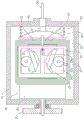
图1是本发明的俯视剖面图。FIG. 1 is a top sectional view of the present invention.
图2是本发明使用时的俯视剖面图。Figure 2 is a top sectional view of the present invention in use.
图3是本发明的连动臂处的俯视剖面图。3 is a top sectional view of the link arm of the present invention.
图4是本发明使用时的连动臂处的俯视剖面图。Fig. 4 is a top sectional view of the link arm when the present invention is in use.
图5是本发明的转子、连动臂及位移盘的立体外观示意图。FIG. 5 is a schematic three-dimensional appearance diagram of the rotor, the linkage arm and the displacement disk of the present invention.
图6是本发明的连动臂及位移盘的侧视连接示意图。6 is a schematic side view of the connection between the linkage arm and the displacement plate of the present invention.
图7是本发明的位移盘的径向轨道示意图。FIG. 7 is a schematic diagram of the radial track of the displacement disk of the present invention.
图8是本发明装设于自行车上的侧视示意图。FIG. 8 is a schematic side view of the present invention installed on a bicycle.
具体实施方式Detailed ways
以下配合附图及本发明的较佳实施例,进一步阐述本发明为达成预定发明目的所采取的技术手段。The technical means adopted by the present invention to achieve the predetermined purpose of the invention are further described below with reference to the accompanying drawings and the preferred embodiments of the present invention.
请参阅图1及图3所示,本发明的自行车无段自动变速装置包含一壳体10、一中心轴20、一动力输入碟31、一动力输出碟32、两转子41、两传动碟42、一离心组件50、一弹性元件60、一输入齿盘71、一轮毂72及一逆转组件80。Please refer to FIG. 1 and FIG. 3 , the stepless automatic transmission device for bicycles of the present invention includes a
前述的壳体10在本实施例中为矩形,但其形状不以此为限;壳体10相对于整台自行车是一固定的组件而不随其他组件转动。The
前述的中心轴20贯穿壳体10,中心轴20即为自行车后轮的轮轴,因此中心轴20同样相对于整台自行车是一固定的组件而不随其他组件转动。The aforementioned
前述的动力输入碟31可转动地设于壳体10内,且可转动地套设于中心轴20外,在本实施例中,动力输入碟31的外侧面贯穿壳体10的壁面,且与壳体10壁面之间设有一轴承33;动力输入碟31的内侧面朝向壳体10的内部突出有一圆锥部311。The aforementioned
前述的动力输出碟32可转动地设于壳体10内,且可转动地套设于中心轴20外,在本实施例中,动力输出碟32的外侧面贯穿壳体10的壁面,且与壳体10壁面之间设有一轴承34;动力输出碟32的内侧面朝向壳体10的内部突出有一圆锥部321;因此,动力输入碟31的圆锥部311及动力输出碟32的圆锥部321相向设置;The aforementioned
在本实施例中,动力输入碟31的圆锥部311的圆锥面的剖面及动力输出碟32的圆锥部321的圆锥面的剖面,均为一内凹的圆弧线(如图1所示),但不以此为限,亦可视情形而改为直线或外凸的圆弧线。In this embodiment, the cross-section of the conical surface of the
前述的两转子41可转动地设于壳体10内,且各转子41与壳体10之间的枢转轴与中心轴20相互垂直。The aforementioned two
前述的两传动碟42分别可转动地设于两转子41上,且各传动碟42与转子41之间的枢转轴与转子41与壳体10之间的枢转轴相互垂直;各传动碟42的相对两侧分别贴靠于动力输入碟31的圆锥部311及动力输出碟32的圆锥部321;当动力输入碟31转动时,该动力输入碟31通过该两传动碟42转动动力输出碟32。The aforementioned two
前述的离心组件50套设于中心轴20外,且连接及带动该两转子41,自行车的车轮转速会带动离心组件50相对中心轴20转动,而离心组件50相对中心轴20转动时,离心组件50会通过离心力的作用进而带动两转子41转动以降低动力输入碟31及动力输出碟32的减速比。The aforementioned
前述的弹性元件60连接及推动离心组件50,并使离心组件50抵抗离心力而带动两转子41逆向转动以提升动力输入碟31及动力输出碟32的减速比。The aforementioned
在本实施例中,离心组件50与动力输出碟32相连接,且被动力输出碟32带动而转动,但不以此为限,离心组件50亦可与动力输入碟31相连接,且被动力输入碟31带动而转动;接下来以离心组件50与动力输出碟32相连接为例进行说明。In this embodiment, the
请参阅图3及图5至图7所示,在本实施例中,离心组件50包含有一套筒51、一位移盘52、多个滚柱53及一连动臂54;Please refer to FIG. 3 and FIG. 5 to FIG. 7 , in this embodiment, the
套筒51可转动地套设于中心轴20外,动力输出碟32的外侧突出于壳体10外,且穿设固定于套筒51中以带动套筒51转动。The
位移盘52可转动地套设于中心轴20外,且可沿中心轴20移动;具体来说,位移盘52可移动地嵌合于套筒51外,即位移盘52会被套筒51带动而转动,但位移盘52仍可相对套筒51移动;具体来说,可使套筒51的外壁面及位移盘52的内壁面为多边形来达成前述功能,但不以此结构为限;借此,位移盘52可通过套筒51而被动力输出碟32带动而转动;The
在本实施例中,位移盘52相邻于壳体10,且位移盘52朝向壳体10的一侧面凹设成形有一圆锥状的容置空间,该圆锥状的容置空间以中心轴20的位置为圆锥的中心;该圆锥状的容置空间的内壁面上设有多条径向轨道521(如图7所示),该等径向轨道521于圆锥状的内壁面上以中心轴20的位置为中心成放射状地延伸。In this embodiment, the
该等滚柱53位于该圆锥状的容置空间中,且该等滚柱53的相对两侧分别贴靠于位移盘52及壳体10的外壁面;各滚柱53具体来说贴靠于位移盘52的径向轨道521中,且可沿着径向轨道521滑动,而位移盘52则通过该等径向轨道521带动该等滚柱53跟着位移盘52转动;请参阅图2及图4所示,当位移盘52转速越快时,跟着转动的滚柱53会因为离心力而逐渐远离中心轴20,并因此沿着圆锥状的内壁面而朝远离壳体10方向地推动该位移盘52;The
请参阅图1、图3、图5及图6所示,弹性元件60朝向该等滚柱53推抵于位移盘52,以使该等滚柱53沿着圆锥状的内壁面朝向中心轴20移动;在其他实施例中,滚柱53亦可改为球体,仅要可以被位移盘52转动,并可通过离心力延沿着圆锥状的内壁面远离中心轴20或朝向中心轴20地移动即可;在本实施例中,弹性元件60为一压缩弹簧,但弹性元件60的位置及形式不以此为限,仅要能朝向滚柱53推动位移盘52即可。Please refer to FIG. 1 , FIG. 3 , FIG. 5 and FIG. 6 , the
连动臂54连接位移盘52及两转子41,当位移盘52相对中心轴20移动时,位移盘52带动连动臂54跟着移动,而连动臂54则连带转动两转子41;在本实施例中,连动臂54上设有一缺口541,位移盘52径向上的周缘可转动地设于缺口541中,并且缺口541的内壁面及位移盘52的径向周缘之间进一步设有多个滚珠542,如此以作为轴承使用,因此不论位移盘52如何转动,都能让其径向周缘保持位于该缺口541内,而当位移盘52移动时,位移盘52仍可带动连动臂54跟着移动;但位移盘52带动连动臂54的结构不以此为限,仅要能无视位移盘52的转动而能直线带动连动臂54即可。The
各转子41的一端的外壁面上环绕设有一环齿部411,该环齿部411的齿可环绕延伸至360度,或只环绕延伸至特定角度亦可,例如在本实施例中,环齿部411的齿仅环绕延伸至180度(如图3所示),但如此已足够进行减速比的调整;The outer wall of one end of each
连动臂54上设有两齿条部543,两齿条部543延伸的方向与中心轴20平行,两齿条部543分别啮合于两转子41的环齿部411,借此当位移盘52带动连动臂54移动时,连动臂54会带动两转子41转动,进而改变两传动碟42的角度,以改变传动碟42抵靠于动力输入碟31的圆锥部311及动力输出碟32的圆锥部321的位置来改变减速比。The
连动臂54带动转子41转动的方式不以前述的齿条部543及环齿部411的啮合为限,仅要能将连动臂54的直线移动转换成转子41的转动即可。The way that the interlocking
连动臂54上设有一导引孔544,导引孔544为一长孔,且其延伸方向与中心轴20平行;壳体10上设有一导引柱11,导引柱11穿设于连动臂54的导引孔544中,借以确保连动臂54仅能沿着中心轴20直线移动。The
离心组件50及弹性元件60的细节结构及位置不以上述为限,例如离心组件50亦可位于壳体10设置动力输入碟31的一侧,并被动力输入碟31转动,这时位移盘52可改相邻于轮毂72,而该等滚柱53改位于轮毂72的内壁面及位移盘52之间等等;或者是离心组件50亦可改为其他结构,仅要可通过离心力来带动两转子41转动即可,或进一步来说,仅要可将离心力转换成直线运动,再通过该直线运动转换成转子41的转动即可;The detailed structures and positions of the
至于弹性元件60,其也可以不连接位移盘52,而改为连接连动臂54来直接拉动连动臂54;或者是,弹性元件60也可以不是压缩弹簧或拉伸弹簧,而改为扭力弹簧并直接连接该两转子41等等,弹性元件60仅要最终能转动两转子41来提升动力输入碟31及动力输出碟32的减速比即可。As for the
请参阅图1及图3所示,前述的输入齿盘71在本实施例中作为最初输入的元件,输入齿盘71连接动力输入碟31,且可带动动力输入碟31转动;在本实施例中,输入齿盘71可转动地套设于中心轴20外,且沿着中心轴20突出有一连接套管711,连接套管711与动力输入碟31相连接。Please refer to FIG. 1 and FIG. 3 , the
前述的轮毂72包覆于壳体10、动力输入碟31、动力输出碟32、两转子41、两传动碟42、离心组件50、弹性元件60及逆转组件80外,中心轴20贯穿轮毂72,输入齿盘71的连接套管711穿设于轮毂72内;轮毂72在本实施例中作为最终输出的元件,轮毂72连接动力输出碟32,且具体来说套设固定于离心组件50的套筒51外,借此动力输出碟32可通过套筒51带动轮毂72转动;在本实施例中,轮毂72与连接套管711之间设有一轴承721;此外,在本实施例中,弹性元件60相对于离心组件50的另一端推抵于轮毂72的内壁面。The
本发明的变速装置的输入及输出不以输入齿盘71及轮毂72为限,亦可依需求而更改。The input and output of the speed change device of the present invention are not limited to the
前述的逆转组件80连接于动力输入碟31或动力输出碟32,逆转组件80可将输入于逆转组件80的转动转换成相反方向的转动后再输出;具体来说,由于动力输入碟31带动传动碟42转动,而传动碟42再带动动力输出碟32转动后,动力输入碟31及动力输出碟32的转动方向会相反,因此逆转组件80可再将转动逆转一次,以使本发明的最初输入及最终输出的转动方向相同;The aforementioned reversing
因此逆转组件80可设于任意位置处,例如可设于最初输入(输入齿盘71)与动力输入碟31之间,或是设于动力输出碟32与最终输出(轮毂72)之间皆可,在本实施例中,逆转组件80及离心组件50分别设于壳体10的相对两侧以缩小整体体积,因此在本实施例中,逆转组件80设于输入齿盘71与动力输入碟31之间。Therefore, the reversing
此外,逆转组件80可为任意结构,仅要能转换转动方向即可,在本实施例中,逆转组件80为一行星齿轮组,且包含有一太阳齿轮81、至少一行星齿轮82、一行星支架83及一内齿轮84;行星支架83固设于壳体10上,输入齿盘71的连接套管711可转动地贯穿行星支架83,在本实施例中,行星支架83与连接套管711之间设有一轴承85;至少一行星齿轮82可自转地设于行星支架83上;内齿轮84及太阳齿轮81的其中之一用以输入逆转组件80的转动(即连接输入齿盘71),内齿轮84及太阳齿轮81的另一用以输出逆转组件80的转动(即连接动力输入碟31);在本实施例中,太阳齿轮81套设固定于输入齿盘71的连接套管711外,内齿轮84套设固定于动力输入碟31突出于壳体10外的部分,但亦可相反,即太阳齿轮81连接动力输入碟31,内齿轮84连接输入齿盘71。In addition, the reversing
请参阅图请参阅图1、图3及图8所示,本发明使用时,设置于自行车的后轮91处,链条92嵌合于套设于输入齿盘71外并带动输入齿盘71转动,输入齿盘71通过逆转组件80带动动力输入碟31转动,动力输入碟31通过传动碟42带动动力输出碟32转动并同时提升转速或降低转速,最后动力输出碟32带动轮毂72转动,轮毂72则带动自行车的后轮91转动。Please refer to the drawings as shown in FIGS. 1 , 3 and 8 , when the present invention is used, it is arranged at the
请参阅图1及图3所示,于刚起步或低转速时,弹性元件60推抵离心组件50使得传动碟42的角度让动力输入碟31及动力输出碟32的减速比较低,因此使用者仅需轻松地踩踏踏板93便可带动后轮91转动;请参阅图2及图4所示,而当踏板轴94转速越来越高后,输入齿盘71转速越来越高,进而使位移盘52转速越来越高,而跟着转动的滚柱53也因离心力而逐渐远离中心轴20而推动位移盘52,位移盘52则通过连动臂54逐渐转动两转子41,转子41便逐渐改变传动碟42的角度来提高动力输入碟31及动力输出碟32的减速比,因此在踏板轴94转速不变的情形下,使用者踩踏踏板93所需的力逐渐增加,但后轮91转速也会逐渐增快,本发明借此无须手动进行任何操作,便可达到自动变速的功效。Please refer to FIG. 1 and FIG. 3 , at the beginning or at low speed, the
本发明除可设置于一般自行车上,亦可设置于电动自行车等等。The present invention can be installed not only on general bicycles, but also on electric bicycles and the like.
以上所述仅是本发明的较佳实施例而已,并非对本发明做任何形式上的限制,虽然本发明已以较佳实施例揭露如上,然而并非用以限定本发明,任何本领域技术人员,在不脱离本发明技术方案的范围内,当可利用上述揭示的技术内容作出些许更动或修饰为等同变化的等效实施例,但凡是未脱离本发明技术方案的内容,依据本发明的技术实质对以上实施例所作的任何简单修改、等同变化与修饰,均仍属于本发明技术方案的范围内。The above descriptions are only preferred embodiments of the present invention, and are not intended to limit the present invention in any form. Although the present invention has been disclosed above with preferred embodiments, it is not intended to limit the present invention. Any person skilled in the art, Within the scope of not departing from the technical solution of the present invention, when the technical content disclosed above can be used to make some changes or modifications to equivalent embodiments with equivalent changes, but any content that does not depart from the technical solution of the present invention, according to the technical solution of the present invention Substantially any simple modifications, equivalent changes and modifications made to the above embodiments still fall within the scope of the technical solutions of the present invention.
Claims (10)
Priority Applications (1)
| Application Number | Priority Date | Filing Date | Title |
|---|---|---|---|
| CN201710992885.1A CN109693757B (en) | 2017-10-23 | 2017-10-23 | Bicycle stepless automatic transmission |
Applications Claiming Priority (1)
| Application Number | Priority Date | Filing Date | Title |
|---|---|---|---|
| CN201710992885.1A CN109693757B (en) | 2017-10-23 | 2017-10-23 | Bicycle stepless automatic transmission |
Publications (2)
| Publication Number | Publication Date |
|---|---|
| CN109693757A CN109693757A (en) | 2019-04-30 |
| CN109693757B true CN109693757B (en) | 2020-06-12 |
Family
ID=66226779
Family Applications (1)
| Application Number | Title | Priority Date | Filing Date |
|---|---|---|---|
| CN201710992885.1A Expired - Fee Related CN109693757B (en) | 2017-10-23 | 2017-10-23 | Bicycle stepless automatic transmission |
Country Status (1)
| Country | Link |
|---|---|
| CN (1) | CN109693757B (en) |
Families Citing this family (2)
| Publication number | Priority date | Publication date | Assignee | Title |
|---|---|---|---|---|
| CN111657802B (en) * | 2020-07-08 | 2025-08-26 | 河北洁仕宝日用塑料制品有限公司 | Self-lifting mop cleaning tool |
| CN212853373U (en) * | 2020-07-08 | 2021-04-02 | 河北洁仕宝日用塑料制品有限公司 | Self-lifting rotary mop |
Citations (4)
| Publication number | Priority date | Publication date | Assignee | Title |
|---|---|---|---|---|
| CN1664411A (en) * | 2004-03-01 | 2005-09-07 | 邱宏勇 | Continuously variable transmission for vehicles |
| WO2006131778A1 (en) * | 2005-06-10 | 2006-12-14 | International Innovations Limited | Continuously variable transmission system |
| CN103879508A (en) * | 2012-12-21 | 2014-06-25 | 株式会社岛野 | Continuously variable bicycle transmission mechanism and bicycle hub |
| CN205013620U (en) * | 2015-09-18 | 2016-02-03 | 湖南农业大学 | Double sphere disk buncher |
Family Cites Families (1)
| Publication number | Priority date | Publication date | Assignee | Title |
|---|---|---|---|---|
| DE102013206710A1 (en) * | 2013-04-15 | 2014-10-16 | Robert Bosch Gmbh | Motor and powered by muscle power vehicle |
-
2017
- 2017-10-23 CN CN201710992885.1A patent/CN109693757B/en not_active Expired - Fee Related
Patent Citations (4)
| Publication number | Priority date | Publication date | Assignee | Title |
|---|---|---|---|---|
| CN1664411A (en) * | 2004-03-01 | 2005-09-07 | 邱宏勇 | Continuously variable transmission for vehicles |
| WO2006131778A1 (en) * | 2005-06-10 | 2006-12-14 | International Innovations Limited | Continuously variable transmission system |
| CN103879508A (en) * | 2012-12-21 | 2014-06-25 | 株式会社岛野 | Continuously variable bicycle transmission mechanism and bicycle hub |
| CN205013620U (en) * | 2015-09-18 | 2016-02-03 | 湖南农业大学 | Double sphere disk buncher |
Also Published As
| Publication number | Publication date |
|---|---|
| CN109693757A (en) | 2019-04-30 |
Similar Documents
| Publication | Publication Date | Title |
|---|---|---|
| CN104100680B (en) | Cycloidal planetary gear speed reducer structure | |
| CN101290041A (en) | Eccentric gear mechanism and method for transmitting rotating force thereby | |
| US9162662B2 (en) | Vehicle brake transmission | |
| CN109693757B (en) | Bicycle stepless automatic transmission | |
| JPH01266089A (en) | Strong drive for bicycle | |
| JP2011007242A (en) | Power transmission mechanism, wheelchair, chain block device, and rotation driving unit | |
| KR101749896B1 (en) | Acceleration and retardation gearing systems | |
| JP4160628B1 (en) | Transmission | |
| JP7178732B2 (en) | Transmission structure | |
| TW201907098A (en) | Planetary gear transmission wherein changes of the gear ratio of the planetary gear transmission can be automatically, smoothly and reliably realized | |
| CN219406786U (en) | Two-stage variable speed output device and hub group of electric vehicle using same | |
| KR101537002B1 (en) | Reducer have trochoid gear | |
| CN201118351Y (en) | Speed-changing bearing speed-reducing hub motor special for electric vehicle | |
| KR101251765B1 (en) | Apparatus of power transmission | |
| US20190359288A1 (en) | Multi-stage transmission bicycle | |
| TWI656061B (en) | Bicycle automatic automatic transmission | |
| CN217994710U (en) | bicycle crank gear | |
| JP7365714B2 (en) | Rotary transmission mechanism | |
| CN218258573U (en) | front derailleur for bicycle | |
| KR101357714B1 (en) | Planetary gear transmission using latch gear | |
| CN202966574U (en) | Central shaft continuously variable speed output mechanism | |
| CN207955892U (en) | The vehicle wheel component and perambulator of perambulator | |
| CN221251631U (en) | Bicycle gear crank device | |
| CA1067723A (en) | Infinitely variable speed drive mechanism | |
| CN223662508U (en) | Miniaturized reduction gear |
Legal Events
| Date | Code | Title | Description |
|---|---|---|---|
| PB01 | Publication | ||
| PB01 | Publication | ||
| SE01 | Entry into force of request for substantive examination | ||
| SE01 | Entry into force of request for substantive examination | ||
| GR01 | Patent grant | ||
| GR01 | Patent grant | ||
| CF01 | Termination of patent right due to non-payment of annual fee |
Granted publication date: 20200612 |
|
| CF01 | Termination of patent right due to non-payment of annual fee |