CN109607451B - An ampoule bottle opener - Google Patents
An ampoule bottle opener Download PDFInfo
- Publication number
- CN109607451B CN109607451B CN201811476594.8A CN201811476594A CN109607451B CN 109607451 B CN109607451 B CN 109607451B CN 201811476594 A CN201811476594 A CN 201811476594A CN 109607451 B CN109607451 B CN 109607451B
- Authority
- CN
- China
- Prior art keywords
- plate
- box body
- fixed
- ampoule bottle
- ampoule
- Prior art date
- Legal status (The legal status is an assumption and is not a legal conclusion. Google has not performed a legal analysis and makes no representation as to the accuracy of the status listed.)
- Expired - Fee Related
Links
Images


Classifications
-
- B—PERFORMING OPERATIONS; TRANSPORTING
- B67—OPENING, CLOSING OR CLEANING BOTTLES, JARS OR SIMILAR CONTAINERS; LIQUID HANDLING
- B67B—APPLYING CLOSURE MEMBERS TO BOTTLES JARS, OR SIMILAR CONTAINERS; OPENING CLOSED CONTAINERS
- B67B7/00—Hand- or power-operated devices for opening closed containers
- B67B7/92—Hand- or power-operated devices for opening closed containers by breaking, e.g. for ampoules
Landscapes
- Engineering & Computer Science (AREA)
- Mechanical Engineering (AREA)
- Devices For Opening Bottles Or Cans (AREA)
Abstract
本发明涉及医疗用具技术领域,尤其涉及一种安瓿瓶开口器,包括盒体,所述盒体内设有至少两个不同高规格的开口机构;所述开口机构包括:动作板、旋转筒、砂片、齿板、弹簧A、固定板和推块;所述盒体内侧设有与动作板配合的滑槽,所述动作板底部固定有齿板;所述动作板上开设有砂片按键孔和推杆按键孔;所述盒体近底部一侧设有环形卡槽,通过所述环形卡槽卡持旋转筒,并通过盒体内部的固定板配合环形卡槽固定旋转筒;所述旋转筒外套设有齿轮,所述齿轮与齿板配合;所述旋转筒的内侧设有定位橡胶圈,通过所述定位橡胶圈卡持安瓿瓶;所述固定板与动作板之间设有弹簧;具有操作简单,功能多样,适用性强的特点。
The invention relates to the technical field of medical appliances, in particular to an ampoule bottle opener, comprising a box body with at least two opening mechanisms of different high specifications; the opening mechanisms include: an action plate, a rotating cylinder, a sand plate, tooth plate, spring A, fixed plate and push block; the inner side of the box body is provided with a chute which is matched with the action plate, the tooth plate is fixed at the bottom of the action plate; the action plate is provided with a key hole for sand sheets and push rod button hole; the box body is provided with an annular slot on the bottom side, through which the rotary drum is clamped, and the rotary drum is fixed by the fixing plate inside the box body with the annular slot; the rotation The outer sleeve is provided with a gear, and the gear cooperates with the toothed plate; the inner side of the rotating cylinder is provided with a positioning rubber ring, and the ampoule bottle is clamped by the positioning rubber ring; a spring is arranged between the fixed plate and the action plate; It has the characteristics of simple operation, diverse functions and strong applicability.
Description
技术领域technical field
本发明涉及医疗用具技术领域,尤其涉及一种安瓿瓶开口器。The invention relates to the technical field of medical appliances, in particular to an ampoule bottle opener.
背景技术Background technique
安瓿瓶是用于盛装药液小型玻璃容器。容量一般为1~25ml,常用于存放注射用药液,也用于口服液的包装,是一种常见的医疗药液储存用品;现代的安瓿是用玻璃管烧制的,由于安瓿瓶具有较高的密封性,能够有效的隔绝空气,广泛运用于盛放注射制剂和必须隔绝空气高纯度化学药品;然而现有的安瓿瓶开口却不易操作,在以往的操作中,医护人员通过医用钳在安瓿瓶的顶部快速敲击从而将安瓿瓶的顶部敲断,从而获得瓶内药液,然而这样的操作方式会因为安瓿瓶个体差异和操作者个人经验而产生差异;显然不是一个科学的开口方式;因此,市面上出现了辅助开口的开口器,而现有的开口器大多是将安瓿瓶进行夹持,然后便于操作者掰断这样的方式,由于在掰断后,瓶口是锋利的玻璃,这使得操作者需要格外的小心,以免掰断的时候手触碰到瓶口从而误伤自己;这样的方式使得现有的安瓿瓶开口器具有不便操作,使用不当易割伤的弊端。Ampoules are small glass containers used to hold medicinal liquids. The capacity is generally 1-25ml, which is often used to store injection liquids, and is also used for the packaging of oral liquids. It is a common medical liquid storage product; modern ampoules are fired with glass tubes. High airtightness can effectively isolate the air, and is widely used to hold injection preparations and high-purity chemicals that must be isolated from the air; however, the opening of the existing ampoule is not easy to operate. The top of the ampoule is knocked off quickly to break the top of the ampoule to obtain the liquid in the bottle. However, this operation method will vary due to the individual differences of the ampoule and the personal experience of the operator; it is obviously not a scientific opening method. Therefore, there are openers with auxiliary openings on the market, and most of the existing openers are to clamp the ampoule bottle, and then it is convenient for the operator to break it off, because after breaking, the bottle mouth is sharp glass, This makes the operator need to be extra careful, so as not to accidentally injure himself by touching the mouth of the bottle when breaking it; this way makes the existing ampoule bottle opener inconvenient to operate and easy to cut when used improperly.
发明内容SUMMARY OF THE INVENTION
有鉴于现有技术的上述缺陷,本发明所要解决的技术问题是提供一种安瓿瓶开口器,能够快速安全的将安瓿瓶顶端开口。In view of the above-mentioned defects of the prior art, the technical problem to be solved by the present invention is to provide an ampoule bottle opener, which can quickly and safely open the top of the ampoule bottle.
为实现上述目的,本发明提供了一种安瓿瓶开口器,包括盒体,所述盒体内设有至少两个不同高规格的开口机构;所述开口机构包括:动作板、旋转筒、砂片、齿板、弹簧A、固定板和推块;所述盒体内侧设有与动作板配合的滑槽,所述动作板底部固定有齿板;所述动作板上开设有砂片按键孔和推杆按键孔;In order to achieve the above purpose, the present invention provides an ampoule bottle opener, including a box body, and the box body is provided with at least two opening mechanisms of different high specifications; the opening mechanisms include: an action plate, a rotating cylinder, a sand sheet , tooth plate, spring A, fixed plate and push block; the inner side of the box body is provided with a chute that cooperates with the action plate, the tooth plate is fixed at the bottom of the action plate; the action plate is provided with sand sheet key holes and Push rod button hole;
所述盒体近底部一侧设有环形卡槽,通过所述环形卡槽卡持旋转筒,并通过盒体内部的固定板配合环形卡槽固定旋转筒;所述旋转筒外套设有齿轮,所述齿轮与齿板配合;所述旋转筒的内侧设有定位橡胶圈,通过所述定位橡胶圈卡持安瓿瓶;The box body is provided with an annular clamping groove on the side near the bottom, through which the rotating cylinder is clamped, and the rotating cylinder is fixed by the fixing plate inside the box body with the annular clamping groove; the rotating cylinder is provided with a gear, The gear is matched with the toothed plate; the inner side of the rotating cylinder is provided with a positioning rubber ring, and the ampoule bottle is clamped by the positioning rubber ring;
所述固定板与动作板之间设有弹簧;所述砂片按键孔上方设有砂片按键,所述砂片按键底部与连杆连接固定,所述连杆的下方通过弹簧B与固定杆连接固定,所述固定杆下方固定有砂片,所述砂片针对安瓿瓶的凹槽处;A spring is arranged between the fixed plate and the action plate; a sand button is arranged above the sand button hole, the bottom of the sand button is connected and fixed with the connecting rod, and the lower part of the connecting rod is connected to the fixing rod through the spring B The connection is fixed, and a sand sheet is fixed under the fixing rod, and the sand sheet is aimed at the groove of the ampoule bottle;
所述推杆按键孔上方设有推杆按键,所述推杆按键底部与连杆B连接固定,所述连杆B下方通过弹簧C与固定杆B连接固定,所述固定杆B下方设有推块。There is a push rod button above the push rod button hole, the bottom of the push rod button is connected and fixed with the connecting rod B, the lower part of the connecting rod B is connected and fixed with the fixing rod B through the spring C, and the lower part of the fixing rod B is provided with Push the block.
进一步的,所述盒体内设有废料通道,所述安瓿瓶的安瓿瓶尖端穿过旋转筒并安瓿瓶尖端插入到废料通道内;所述推块位于废料通道内。Further, the box body is provided with a waste channel, the ampoule tip of the ampoule bottle passes through the rotating cylinder and the ampoule bottle tip is inserted into the waste channel; the push block is located in the waste channel.
进一步的,所述盒体的侧板上设有凹口,所述凹口的侧面固定有起钉。Further, the side plate of the box body is provided with a notch, and the side surface of the notch is fixed with a nail.
进一步的,所述盒体的侧板前端还设有金属块。Further, the front end of the side plate of the box body is also provided with a metal block.
进一步的,所述弹簧A内设有限位柱。Further, the spring A is provided with a limit post.
进一步的,所述盒体的后端设有握把。Further, the rear end of the box body is provided with a handle.
本发明的有益效果是:The beneficial effects of the present invention are:
1、本结构通过套筒内的定位橡胶圈卡持安瓿瓶(插入过程中,直至推不动,即被定位橡胶圈卡持住),然后在下压动作板时,带动齿板配合套筒外的齿轮转动(通过定位橡胶圈与安瓿瓶之间的摩擦力带动安瓿瓶转动),从而通过下压转换为安瓿瓶的转动;而此时,只需按动砂片按键推动砂片与安瓿瓶的凹槽处接触,而由于弹簧B的存在,使得砂片时刻与安瓿瓶的外周接触,在安瓿瓶受压转动时,砂片能够在安瓿瓶外画出划痕,从而通过下压推杆按键,通过推杆按键下方的推块推动安瓿瓶尖端,从而实现掰断这个过程;而设置的废料通道,当安瓿瓶尖端被掰断后,能够进入到废料通道掉出;具有操作简单,功能多样,适用性强的特点。1. This structure holds the ampoule bottle by the positioning rubber ring in the sleeve (in the process of inserting, it is held by the positioning rubber ring until it cannot be pushed), and then when the action plate is pressed down, the tooth plate is driven to fit the outside of the sleeve. The gear rotates (the ampoule is rotated by the friction between the positioning rubber ring and the ampoule), which is converted into the rotation of the ampoule by pressing down; at this time, just press the sand button to push the sand and the ampoule. Because of the existence of the spring B, the sand sheet is always in contact with the outer circumference of the ampoule bottle. When the ampoule bottle is rotated under pressure, the sand sheet can draw scratches on the outside of the ampoule bottle, so that by pressing down the push rod Press the button to push the tip of the ampoule bottle through the push block below the push rod button, so as to realize the process of breaking; and the set waste channel, when the tip of the ampoule bottle is broken, can enter the waste channel and fall out; it has simple operation and various functions , the feature of strong applicability.
2、而在盒体内设置的不同规格旋转筒,从而能够实现对不同规格的安瓿瓶进行掰断;2. The rotating cylinders of different specifications set in the box body can realize the breaking of ampoules of different specifications;
3、而设计起钉和金属块配合把手是便于习惯常规操作的医护人员,通过手握把手依然能够直接通过金属块击碎安瓿瓶顶段;而通过起钉来实现开启药瓶盖,增加本结构的功能选择。3. The design of the nail and the metal block with the handle is convenient for medical staff who are used to routine operations. By holding the handle, the top section of the ampoule can still be broken directly through the metal block; Functional selection of structures.
附图说明Description of drawings
图1是本发明具体实施方式的正面结构示意图;Fig. 1 is the front structure schematic diagram of the specific embodiment of the present invention;
图2是本发明具体实施方式的盒体顶部俯视结构示意图;Fig. 2 is the top plan structure schematic diagram of the box body according to the specific embodiment of the present invention;
图3是本发明的安瓿瓶结构示意图;Fig. 3 is the ampoule structure schematic diagram of the present invention;
图4是本发明的具体实施方式的盒体内部机构示意图。FIG. 4 is a schematic diagram of the internal mechanism of the box body according to the specific embodiment of the present invention.
具体实施方式Detailed ways
为使本发明的上述目的、特征和优点能够更加明显易懂,下面结合附图对本发明的具体实施方式做详细的说明。在下面的描述中阐述了很多具体细节以便于充分理解本发明。但是本发明能够以很多不同于在此描述的其它方式来实施,本领域技术人员可以在不违背本发明内涵的情况下做类似改进,因此发明不受下面公开的具体实施的限制。In order to make the above objects, features and advantages of the present invention more clearly understood, the specific embodiments of the present invention will be described in detail below with reference to the accompanying drawings. In the following description, numerous specific details are set forth in order to provide a thorough understanding of the present invention. However, the present invention can be implemented in many other ways different from those described herein, and those skilled in the art can make similar improvements without departing from the connotation of the present invention, so the invention is not limited by the specific implementation disclosed below.
下面结合附图1-4对本发明进一步的解释,一种安瓿瓶开口器,包括盒体1,盒体1内设有至少两个不同高规格的开口机构;从而通过不同规格开口机构适应不同规格的安瓿瓶,从而让本发明更加的具有适用性;The present invention will be further explained below in conjunction with accompanying drawings 1-4. An ampoule bottle opener includes a
开口机构包括:动作板2、旋转筒3、砂片4、齿板5、弹簧A6、固定板12和推块7;盒体1内侧设有与动作板2配合的滑槽8,动作板2底部固定有齿板5;动作板2上开设有砂片按键孔9和推杆按键孔10;The opening mechanism includes: an
盒体1近底部一侧设有环形卡槽11,通过环形卡槽11卡持旋转筒3,并通过盒体1内部的固定板12配合环形卡槽11固定旋转筒3;旋转筒3外套设有齿轮13,齿轮13与齿板5配合;旋转筒3的内侧设有定位橡胶圈14,通过定位橡胶圈14卡持安瓿瓶15;The
在上述机构中,通过旋转筒3内的定位橡胶圈14卡持住安瓿瓶,从而在下呀定位板2时,齿板5带动旋转筒3转动,在定位橡胶圈14与安瓿瓶15之间的摩擦力带动安瓿瓶转动;In the above mechanism, the ampoule bottle is held by the positioning
在进一步的设置中,固定板12与动作板2之间设有弹簧A6;砂片按键孔9上方设有砂片按键16,砂片按键16底部与连杆17连接固定,连杆17的下方通过弹簧B18与固定杆19连接固定,固定杆19下方固定有砂片4,砂片4针对安瓿瓶的凹槽处151;In a further setting, a spring A6 is arranged between the fixed plate 12 and the
在上述结构中,通过弹簧A6能够将被下压的动作板2回弹,便于进行下一步操作;而砂片按键16配合弹簧B18及砂片4的存在,是保证砂片4与安瓿瓶15接触后具有压力,能够在安瓿瓶旋转的情况下划出划痕。In the above structure, the pressed
在进一步的设置中,推杆按键孔10上方设有推杆按键20,推杆按键20底部与连杆B21连接固定,连杆B21下方通过弹簧C22与固定杆B23连接固定,固定杆B23下方设有推块7。In a further arrangement, a
在上述结构中,通过推杆按键20下压控制推块7下压安瓿瓶尖端152,而设置的弹簧C22便是为了下压时是一个逐渐增大的力,最后将安瓿瓶尖端152推断。In the above structure, the control push block 7 is pressed down by the
在进一步的设置中,盒体1内设有废料通道24,安瓿瓶15的安瓿瓶尖端152穿过旋转筒3并安瓿瓶尖端插入到废料通道24内;推块7位于废料通道24内。In a further arrangement, the
在上述结构中,设置的废料通道24便于将安瓿瓶尖端152回收,在安瓿瓶尖端被推断后,能够进入到废料通道24,掉出盒体1。In the above structure, the
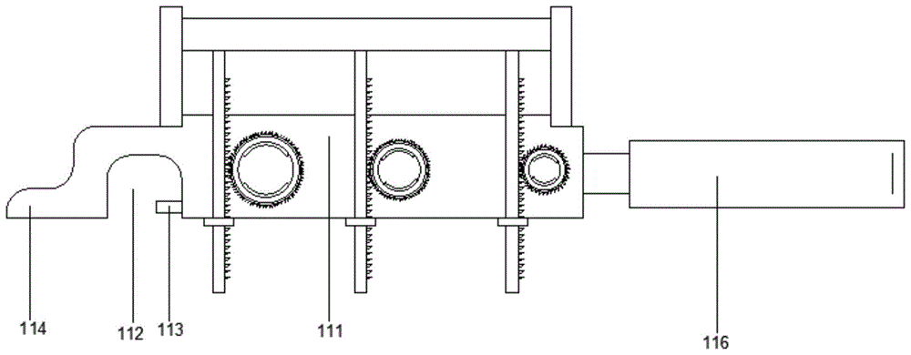
在进一步的设置中,盒体1的侧板111上设有凹口112,凹口112的侧面固定有起钉113;盒体1的侧板111前端还设有金属块114;弹簧A6内设有限位柱115;盒体1的后端设有握把116。In a further setting, the
在上述设置中,凹口112配合起钉113来完成对药瓶瓶盖的开启,起子结构;通过手握把手116,然后通过金属块114依然能够延续以往用硬物敲击安瓿瓶顶端的操作方式;而限位柱115的存在是防止下压弧度不必要的过大。In the above setting, the
本结构的主要操作过程是,将安瓿瓶15插入到旋转筒3内,直至安瓿瓶15抵拢定位橡胶圈14,然后下压动作板2、推杆按键20和砂片按键16;此时,齿板5的下降带动旋转筒3转动,定位橡胶圈14带动安瓿瓶15转动,当推杆按键20下压时,推动砂片4与安瓿瓶15的凹槽处151接触,由于安瓿瓶在转动,会在安瓿瓶外周划出划痕,然后在下呀推杆按键20时,推杆按键16带动推块7下呀安瓿瓶尖端152,直至安瓿瓶尖端152被掰断;安瓿瓶尖端152掉入到废料通道24,从另一侧掉出盒体1。The main operation process of this structure is to insert the
通过套筒内的定位橡胶圈卡持安瓿瓶(插入过程中,直至推不动,即被定位橡胶圈卡持住),然后在下压动作板时,带动齿板配合套筒外的齿轮转动(通过定位橡胶圈与安瓿瓶之间的摩擦力带动安瓿瓶转动),从而通过下压转换为安瓿瓶的转动;而此时,只需按动砂片按键推动砂片与安瓿瓶的凹槽处接触,而由于弹簧B的存在,使得砂片时刻与安瓿瓶的外周接触,在安瓿瓶受压转动时,砂片能够在安瓿瓶外画出划痕,从而通过下压推杆按键,通过推杆按键下方的推块推动安瓿瓶尖端,从而实现掰断这个过程;而设置的废料通道,当安瓿瓶尖端被掰断后,能够进入到废料通道掉出;The ampoule bottle is held by the positioning rubber ring in the sleeve (during the insertion process, it is held by the positioning rubber ring until it cannot be pushed), and then when the action plate is pressed down, the tooth plate is driven to rotate with the gear outside the sleeve ( The ampoule is rotated by the friction between the positioning rubber ring and the ampoule), which is converted into the rotation of the ampoule by pressing down; at this time, just press the sand sheet button to push the sand sheet and the groove of the ampoule bottle. Due to the existence of the spring B, the sand sheet is always in contact with the outer circumference of the ampoule bottle. When the ampoule bottle is pressed and rotated, the sand sheet can draw scratches on the outside of the ampoule bottle. The push block under the lever button pushes the tip of the ampoule bottle to realize the breaking process; and the set waste channel, when the tip of the ampoule bottle is broken, can enter the waste channel and fall out;
以上详细描述了本发明的较佳具体实施例。应当理解,本领域的普通技术人员无需创造性劳动就可以根据本发明的构思做出诸多修改和变化。因此,凡本技术领域中技术人员依本发明的构思在现有技术的基础上通过逻辑分析、推理或者有限的实验可以得到的技术方案,皆应在由权利要求书所确定的保护范围内。The preferred embodiments of the present invention have been described in detail above. It should be understood that those skilled in the art can make numerous modifications and changes according to the concept of the present invention without creative efforts. Therefore, all technical solutions that can be obtained by those skilled in the art through logical analysis, reasoning or limited experiments on the basis of the prior art according to the concept of the present invention shall fall within the protection scope determined by the claims.
Claims (5)
Priority Applications (1)
| Application Number | Priority Date | Filing Date | Title |
|---|---|---|---|
| CN201811476594.8A CN109607451B (en) | 2018-12-05 | 2018-12-05 | An ampoule bottle opener |
Applications Claiming Priority (1)
| Application Number | Priority Date | Filing Date | Title |
|---|---|---|---|
| CN201811476594.8A CN109607451B (en) | 2018-12-05 | 2018-12-05 | An ampoule bottle opener |
Publications (2)
| Publication Number | Publication Date |
|---|---|
| CN109607451A CN109607451A (en) | 2019-04-12 |
| CN109607451B true CN109607451B (en) | 2020-11-27 |
Family
ID=66006441
Family Applications (1)
| Application Number | Title | Priority Date | Filing Date |
|---|---|---|---|
| CN201811476594.8A Expired - Fee Related CN109607451B (en) | 2018-12-05 | 2018-12-05 | An ampoule bottle opener |
Country Status (1)
| Country | Link |
|---|---|
| CN (1) | CN109607451B (en) |
Families Citing this family (2)
| Publication number | Priority date | Publication date | Assignee | Title |
|---|---|---|---|---|
| CN114074910A (en) * | 2020-08-19 | 2022-02-22 | 首都医科大学附属北京朝阳医院 | Rotary disc device capable of rapidly breaking ampoule to draw liquid medicine in ICU rescue |
| CN114074908A (en) * | 2020-08-19 | 2022-02-22 | 首都医科大学附属北京朝阳医院 | Breaking assembly capable of quickly breaking ampoule in ICU rescue so as to be convenient for extracting liquid medicine in device |
Family Cites Families (15)
| Publication number | Priority date | Publication date | Assignee | Title |
|---|---|---|---|---|
| US3154230A (en) * | 1961-09-12 | 1964-10-27 | Anrep Rene | Bulbs or similar vessels and method for manufacturing same |
| JPS5322601Y2 (en) * | 1973-11-15 | 1978-06-12 | ||
| DE69900513T2 (en) * | 1998-02-09 | 2002-07-04 | Asdve, Nemours | Safety device for cutting the neck part of a champagne bottle and device equipped with such a device |
| US6296149B1 (en) * | 1999-04-16 | 2001-10-02 | Depuy Orthopaedics, Inc. | Monomer delivery device for bone cement delivery system |
| CN103708394B (en) * | 2013-12-29 | 2015-12-30 | 宁波市鄞州云帆工程咨询有限公司 | Coaxial drawing and pulling type ampoule opener |
| CN105314573A (en) * | 2014-06-18 | 2016-02-10 | 戴学良 | Medical injection drug cutter |
| KR101720301B1 (en) * | 2015-09-23 | 2017-03-27 | 박재일 | Automatic cutting apparatus for ampoule |
| CN206692298U (en) * | 2017-02-13 | 2017-12-01 | 梁斌 | A kind of medical ampoule bottle opener |
| CN206751357U (en) * | 2017-05-16 | 2017-12-15 | 贾芸玲 | Opener for ampoule |
| CN207142805U (en) * | 2017-06-21 | 2018-03-27 | 中国人民解放军第三军医大学第二附属医院 | A kind of bottle opener for ampoule bottles |
| CN107473156B (en) * | 2017-08-24 | 2019-03-22 | 平顶山学院 | A medical liquid injection bottle mouth cutting device |
| CN207418249U (en) * | 2017-10-28 | 2018-05-29 | 郑州大学 | Medical abrasive wheel bottle opener |
| CN207933014U (en) * | 2018-03-14 | 2018-10-02 | 中国人民解放军陆军军医大学第一附属医院 | A kind of Ampoule bottle opener |
| CN207957710U (en) * | 2018-03-15 | 2018-10-12 | 余小健 | A kind of ampoule bottle bottle opening device |
| CN208071273U (en) * | 2018-04-03 | 2018-11-09 | 灌南县中医院 | A kind of medical multifunctional bottle cap opener |
-
2018
- 2018-12-05 CN CN201811476594.8A patent/CN109607451B/en not_active Expired - Fee Related
Also Published As
| Publication number | Publication date |
|---|---|
| CN109607451A (en) | 2019-04-12 |
Similar Documents
| Publication | Publication Date | Title |
|---|---|---|
| CN109607451B (en) | An ampoule bottle opener | |
| CN208856881U (en) | Ampoule Opener | |
| CN110357017B (en) | Safety standard ampoule bottle breaking device and using method thereof | |
| CN113104792B (en) | Ampoule bottle mouth removing device for pediatrics | |
| CN108658025B (en) | A simple bottle opening device for ampoules | |
| CN207933014U (en) | A kind of Ampoule bottle opener | |
| US3967512A (en) | Cork remover | |
| CN214780657U (en) | Opener for ampoule bottle | |
| CN212246163U (en) | An ampoule bottle opening device | |
| CN211871344U (en) | A simple ampoule opener for nursing | |
| CN209442600U (en) | A kind of Ampoule bottle opener | |
| CN215287929U (en) | Ampoule bottle opener | |
| CN212997459U (en) | XiLin bottle is with preventing stabbing protector | |
| CN221565769U (en) | Ampoule bottle opener | |
| CN220078573U (en) | Auxiliary bottle opener for ampoule bottle | |
| CN212799569U (en) | Multifunctional bottle opening device | |
| CN220182734U (en) | A tool for breaking ampoules | |
| CN220201383U (en) | Ampoule bottle opening breaking device | |
| CN217323323U (en) | Ann cuts open a bottle uncork device | |
| CN220158939U (en) | A sharps box for quickly twisting insulin needles | |
| CN207760006U (en) | A kind of portable powder bottle lid arrangement | |
| CN217377259U (en) | Ampoule bottle opening device for first aid | |
| CN211255202U (en) | Electric bottle opener | |
| CN223357372U (en) | Ampoule bottle opener | |
| CN207483325U (en) | A kind of peace cuts open bottle cutting and takes liquid integrated device |
Legal Events
| Date | Code | Title | Description |
|---|---|---|---|
| PB01 | Publication | ||
| PB01 | Publication | ||
| SE01 | Entry into force of request for substantive examination | ||
| SE01 | Entry into force of request for substantive examination | ||
| GR01 | Patent grant | ||
| GR01 | Patent grant | ||
| CF01 | Termination of patent right due to non-payment of annual fee |
Granted publication date: 20201127 Termination date: 20211205 |
|
| CF01 | Termination of patent right due to non-payment of annual fee |