CN109441219B - Road construction warning isolating device - Google Patents
Road construction warning isolating device Download PDFInfo
- Publication number
- CN109441219B CN109441219B CN201811514543.XA CN201811514543A CN109441219B CN 109441219 B CN109441219 B CN 109441219B CN 201811514543 A CN201811514543 A CN 201811514543A CN 109441219 B CN109441219 B CN 109441219B
- Authority
- CN
- China
- Prior art keywords
- isolation
- fixedly connected
- movable frame
- column
- rod
- Prior art date
- Legal status (The legal status is an assumption and is not a legal conclusion. Google has not performed a legal analysis and makes no representation as to the accuracy of the status listed.)
- Active
Links
- 238000010276 construction Methods 0.000 title claims abstract description 31
- XLYOFNOQVPJJNP-UHFFFAOYSA-N water Substances O XLYOFNOQVPJJNP-UHFFFAOYSA-N 0.000 claims abstract description 117
- 238000002955 isolation Methods 0.000 claims abstract description 100
- 230000002093 peripheral effect Effects 0.000 claims abstract description 27
- 229920000742 Cotton Polymers 0.000 claims abstract description 11
- 230000030279 gene silencing Effects 0.000 claims abstract description 10
- 238000007789 sealing Methods 0.000 claims description 23
- 230000006698 induction Effects 0.000 claims description 6
- 230000000149 penetrating effect Effects 0.000 claims description 3
- 239000000428 dust Substances 0.000 abstract description 9
- 125000006850 spacer group Chemical group 0.000 abstract description 2
- 230000000694 effects Effects 0.000 description 6
- 238000000034 method Methods 0.000 description 6
- 230000008569 process Effects 0.000 description 6
- 238000000926 separation method Methods 0.000 description 4
- 230000009286 beneficial effect Effects 0.000 description 3
- 239000000463 material Substances 0.000 description 3
- 238000010248 power generation Methods 0.000 description 3
- 239000007921 spray Substances 0.000 description 3
- 230000008901 benefit Effects 0.000 description 2
- 230000005611 electricity Effects 0.000 description 2
- 230000009323 psychological health Effects 0.000 description 2
- 238000010521 absorption reaction Methods 0.000 description 1
- 230000009471 action Effects 0.000 description 1
- 230000006835 compression Effects 0.000 description 1
- 238000007906 compression Methods 0.000 description 1
- 238000001125 extrusion Methods 0.000 description 1
- 230000036541 health Effects 0.000 description 1
- 230000006872 improvement Effects 0.000 description 1
- 239000000696 magnetic material Substances 0.000 description 1
- 238000012986 modification Methods 0.000 description 1
- 230000004048 modification Effects 0.000 description 1
- 238000012544 monitoring process Methods 0.000 description 1
- 239000000047 product Substances 0.000 description 1
- 238000011084 recovery Methods 0.000 description 1
- 230000001105 regulatory effect Effects 0.000 description 1
- 239000013589 supplement Substances 0.000 description 1
- 239000002699 waste material Substances 0.000 description 1
Images


Classifications
-
- E—FIXED CONSTRUCTIONS
- E04—BUILDING
- E04H—BUILDINGS OR LIKE STRUCTURES FOR PARTICULAR PURPOSES; SWIMMING OR SPLASH BATHS OR POOLS; MASTS; FENCING; TENTS OR CANOPIES, IN GENERAL
- E04H17/00—Fencing, e.g. fences, enclosures, corrals
- E04H17/14—Fences constructed of rigid elements, e.g. with additional wire fillings or with posts
-
- E—FIXED CONSTRUCTIONS
- E01—CONSTRUCTION OF ROADS, RAILWAYS, OR BRIDGES
- E01H—STREET CLEANING; CLEANING OF PERMANENT WAYS; CLEANING BEACHES; DISPERSING OR PREVENTING FOG IN GENERAL CLEANING STREET OR RAILWAY FURNITURE OR TUNNEL WALLS
- E01H3/00—Applying liquids to roads or like surfaces, e.g. for dust control; Stationary flushing devices
- E01H3/04—Fixed devices, e.g. permanently- installed flushing means
-
- E—FIXED CONSTRUCTIONS
- E04—BUILDING
- E04B—GENERAL BUILDING CONSTRUCTIONS; WALLS, e.g. PARTITIONS; ROOFS; FLOORS; CEILINGS; INSULATION OR OTHER PROTECTION OF BUILDINGS
- E04B1/00—Constructions in general; Structures which are not restricted either to walls, e.g. partitions, or floors or ceilings or roofs
- E04B1/62—Insulation or other protection; Elements or use of specified material therefor
- E04B1/74—Heat, sound or noise insulation, absorption, or reflection; Other building methods affording favourable thermal or acoustical conditions, e.g. accumulating of heat within walls
- E04B1/82—Heat, sound or noise insulation, absorption, or reflection; Other building methods affording favourable thermal or acoustical conditions, e.g. accumulating of heat within walls specifically with respect to sound only
-
- E—FIXED CONSTRUCTIONS
- E04—BUILDING
- E04H—BUILDINGS OR LIKE STRUCTURES FOR PARTICULAR PURPOSES; SWIMMING OR SPLASH BATHS OR POOLS; MASTS; FENCING; TENTS OR CANOPIES, IN GENERAL
- E04H17/00—Fencing, e.g. fences, enclosures, corrals
- E04H17/14—Fences constructed of rigid elements, e.g. with additional wire fillings or with posts
- E04H17/20—Posts therefor
- E04H17/22—Anchoring means therefor, e.g. specially-shaped parts entering the ground; Struts or the like
-
- H—ELECTRICITY
- H02—GENERATION; CONVERSION OR DISTRIBUTION OF ELECTRIC POWER
- H02K—DYNAMO-ELECTRIC MACHINES
- H02K35/00—Generators with reciprocating, oscillating or vibrating coil system, magnet, armature or other part of the magnetic circuit
- H02K35/02—Generators with reciprocating, oscillating or vibrating coil system, magnet, armature or other part of the magnetic circuit with moving magnets and stationary coil systems
Landscapes
- Engineering & Computer Science (AREA)
- Architecture (AREA)
- Civil Engineering (AREA)
- Structural Engineering (AREA)
- Physics & Mathematics (AREA)
- Acoustics & Sound (AREA)
- Electromagnetism (AREA)
- Power Engineering (AREA)
- Road Signs Or Road Markings (AREA)
Abstract
The invention discloses a road construction warning isolation device, and relates to the technical field of road engineering. The invention comprises a first isolation column and a second isolation column, wherein a warning screen is arranged on one surface of the first isolation column; the upper surface of the first isolation column is fixedly communicated with a water inlet pipe; the opposite surface of the first isolation column is fixedly connected with four fixed blocks; a first movable frame is fixedly connected to one surface of the first isolation column; four sliding chutes are arranged on the peripheral side surface of the first movable frame. The invention solves the problem that the existing road construction warning isolation device has no dust removal device by arranging a plurality of water outlet pipes; by arranging the fixed block and the movable isolating rod, the problems that the existing road construction warning isolating device is fixed in length and is not easy to disassemble are solved; through set up the amortization cotton on adjustable shelf and spacer bar, solved current road construction and warned the problem that isolating device does not have dust collector and does not have silencing device.
Description
Technical Field
The invention belongs to the technical field of road engineering, and particularly relates to a road construction warning isolation device.
Background
Road engineering refers to the whole process of planning, designing, constructing, maintaining and managing work performed by taking a road as an object and the engineering entity engaged in the whole process. Road works, like civil engineering of any other gate type, have obvious technical, economic and regulatory aspects.
The existing road construction warning isolation device is not provided with a dust removal device, so that a large amount of dust is generated in the road construction process, the health of workers is not facilitated, and the environment is polluted; the existing road construction warning isolation device has fixed length and is not easy to disassemble, and is inconvenient for workers in the using and transporting processes; the existing road construction warning isolation device is not provided with a dust removal device and a silencing device, can generate great noise in the road construction process, and is not beneficial to physical and psychological health of workers.
Disclosure of Invention
The invention aims to provide a road construction warning isolation device, which solves the problem that the existing road construction warning isolation device has no dust removal device by arranging a plurality of water outlet pipes; by arranging the fixed block and the movable isolating rod, the problems that the existing road construction warning isolating device is fixed in length and is not easy to disassemble are solved; through set up the amortization cotton on adjustable shelf and spacer bar, solved current road construction and warned the problem that isolating device does not have dust collector and does not have silencing device.
In order to solve the technical problems, the invention is realized by the following technical scheme:
the invention relates to a road construction warning isolation device, which comprises a first isolation column and a second isolation column, wherein a warning screen is arranged on one surface of the first isolation column; the upper surface of the first isolation column is fixedly communicated with a water inlet pipe; the opposite surface of the first isolation column is fixedly connected with four fixed blocks; a first movable frame is fixedly connected to one surface of the first isolation column; four sliding chutes are formed on the peripheral side surface of the first movable frame; wherein the inner surfaces of the two sliding chutes are connected with two sliding rods in a sliding manner; two ends of the two sliding rods are fixedly connected with a limiting piece; wherein, the peripheral side surfaces of the two slide bars are rotatably connected with a round pipe; the peripheral side surface of the circular tube is fixedly connected with a first isolating rod; a straight rod is rotatably connected to one surface of the first isolating rod; the other end of the first isolating rod is rotatably connected with a second movable frame; a second isolating rod is rotatably connected to one surface of the second movable frame; the other end of the second isolating rod is rotatably connected with a third movable frame; a third isolating rod is rotatably connected to one surface of the third movable frame; the other end of the third isolating rod is rotatably connected with a fourth movable frame; one surface of the fourth movable frame is fixedly connected with the second isolation column; the inner surface of the first isolation column is fixedly connected with a water pump; a first water outlet pipe is fixedly connected with the water outlet end of the water pump; the other end of the first water outlet pipe penetrates through one surface of the first isolation column and is fixedly connected with the first isolation column; the other end of the first water outlet pipe is fixedly communicated with a second water outlet pipe and a third water outlet pipe through a hose; one end of the second water outlet pipe and one end of the third water outlet pipe are respectively and fixedly connected with the upper surface of the first movable frame and the upper surface of the second movable frame; a first sliding plate and a second sliding plate are arranged in the first isolation column, a plurality of connecting columns are fixedly connected between the first sliding plate and the second sliding plate, a heavy block is fixedly connected on the first sliding plate, a connecting rope is arranged on the heavy block, a rotating wheel and a rotating handle are arranged at the upper end of the connecting rope penetrating through the first isolation column, a first water through hole is arranged at the edge of the first sliding plate, a first one-way valve is arranged below the first water through hole, a second water through hole is arranged at the position of the second sliding plate close to the first water outlet pipe, a second one-way valve is arranged at the lower end of the second water through hole, a third one-way valve is arranged at the position of the lower end of the first water outlet pipe close to the water pump, a limiting column higher than the water pump is arranged at the bottom of the first isolation column, and a hollow cavity is arranged in the second sliding plate, the utility model discloses a safety device, including cavity, push pedal, sealed hypoplastron, the cavity is provided with the recovery spring in the cavity the free end of recovering the spring is provided with the push pedal, the push pedal opposite side is provided with the push rod, the push rod through the pivot with fly leaf fixed connection second slide top is provided with sealed upper plate the second slide with be provided with the telescopic link between the sealed upper plate, the sealed hypoplastron is connected to the other end of telescopic link, sealed hypoplastron with the fly leaf passes through pivot fixed connection the inner wall one side that the pouring weight is close to first insulated column is provided with third magnet, is provided with from power generation facility between two upper.
Further, the self-generating device comprises a sealing cavity, a micro cavity, a first magnet, a second magnet, an induction coil and a vibration spring, the sealing cavity is located between the two fixing blocks, the micro cavity is arranged inside the sealing cavity, the induction coil is arranged on the outer surface of the micro cavity, the vibration spring is fixedly connected to the bottom of the micro cavity, the second magnet is fixedly connected to the other end of the vibration spring, a spacing column is arranged above the second magnet, the first magnet is arranged on the spacing column, the magnetic poles of the first magnet corresponding to the third magnet are opposite in polarity, and the magnetic poles of the second magnet are located on two sides in the vertical direction.
Further, the internal structure of the second isolation column is the same as that of the first isolation column.
Further, the second movable frame inner structure, the third movable frame inner structure and the fourth movable frame inner structure are all the same as the first movable frame inner structure.
Furthermore, the lower surfaces of the first isolation column and the second isolation column are fixedly connected with four universal wheels; and the four universal wheels are respectively provided with a brake block.
Furthermore, the water outlet end of the second water outlet pipe and the water outlet end of the third water outlet pipe are fixedly connected with an electromagnetic valve.
Furthermore, the peripheral side surface of the first movable frame, the peripheral side surface of the second movable frame, the peripheral side surface of the third movable frame and the peripheral side surface of the fourth movable frame are fixedly connected with silencing cotton; the first isolating rod circumferential side face, the second isolating rod circumferential side face and the third isolating rod circumferential side face are fixedly connected with silencing cotton.
Furthermore, the thickness of the first isolation rod, the thickness of the second isolation rod and the thickness of the third isolation rod are all smaller than the thickness of the sliding groove, and the difference value is within the range of 5cm-7cm, so that the first isolation rod, the second isolation rod and the third isolation rod can move in the sliding groove conveniently.
The invention has the following beneficial effects:
1. the road construction warning isolation device comprises a plurality of water outlet pipes, wherein the water outlet pipes are arranged on the road construction warning isolation device, and the water outlet pipes are connected with the water outlet pipes.
2. The road construction warning isolation device comprises a fixed block, a movable isolation rod and a fixing block, wherein the fixed block is arranged on the fixed block, the movable isolation rod is arranged on the fixed block, the fixed block is connected with the movable isolation rod, and the fixing block is connected with the movable isolation rod.
3. The silencing cotton is arranged on the movable frame and the isolation rod, so that the problems that an existing road construction warning isolation device is not provided with a dust removal device or a silencing device, and can generate large noise in the road construction process, and the noise is not beneficial to physical and psychological health of workers are solved, and the silencing cotton can effectively absorb the noise and has the advantage of reducing noise pollution.
4. The invention realizes the water extrusion in the large space at the bottom by the second sliding plate and the internal telescopic structure thereof under the condition of the non-external power supply and the condition of the burning out of a water pump caused by the failure of accurately and timely switching off the water pump due to the power supply, the first sliding plate is pushed by the weight to move and compress water so that the water can be sprayed out from a water outlet pipe, the automatic stopping at the bottom is realized by the action of the connecting rope, and under the condition that the bottom has the large space, the water is extruded in the large space at the bottom by the second sliding plate and the internal telescopic structure thereof, the water storage device is characterized in that the water inlet pipe is provided with a first magnet, a second magnet, a third one-way valve and a magnet, wherein the first magnet, the second magnet and the third one-way valve are arranged on the water inlet pipe, the third one-way valve and the third one-way valve are arranged.
Of course, it is not necessary for any product in which the invention is practiced to achieve all of the above-described advantages at the same time.
Drawings
In order to more clearly illustrate the technical solutions of the embodiments of the present invention, the drawings used in the description of the embodiments will be briefly introduced below, and it is obvious that the drawings in the following description are only some embodiments of the present invention, and it is obvious for those skilled in the art that other drawings can be obtained according to the drawings without creative efforts.
FIG. 1 is a schematic structural view of a road construction warning isolation device of the present invention;
FIG. 2 is an enlarged view of a portion of FIG. 1 at A;
FIG. 3 is an enlarged view of a portion of FIG. 1 at B;
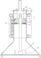
FIG. 4 is a structural cross-sectional view of a first separator column;
FIG. 5 is a sectional view showing a detailed structure of a first separation column;
FIG. 6 is an enlarged view of a portion of FIG. 5 at C;
fig. 7 is a partial enlarged view of fig. 5 at D.
In the drawings, the components represented by the respective reference numerals are listed below:
1-a first isolating column, 2-a second isolating column, 3-a warning screen, 4-a water inlet pipe, 5-a fixed block, 6-a first movable frame, 7-a chute, 8-a sliding rod, 9-a limiting sheet, 10-a round pipe, 11-a first isolating rod, 12-a straight rod, 13-a second movable frame, 14-a second isolating rod, 15-a third movable frame, 16-a third isolating rod, 17-a fourth movable frame, 18-a water pump, 19-a first water outlet pipe, 20-a hose, 21-a second water outlet pipe, 22-a third water outlet pipe, 23-a first sliding plate, 24-a heavy block, 25-a connecting column, 26-a second sliding plate, 27-a connecting rope, 28-a rotating wheel, 29-a rotating handle, 30-a groove and 31-a fixed plate, 32-self-generating device, 33-first water through hole, 34-first check valve, 35-sealing cavity, 36-micro cavity, 37-first magnet, 38-second magnet, 39-induction coil, 40-vibration spring, 41-hollow cavity, 42-sealing upper plate, 43-second water through hole, 44-second check valve, 45-restoring spring, 46-push plate, 47-push rod, 48-sealing lower plate, 49-sealing block, 50-movable plate, 51-telescopic rod, 101-universal wheel, 102-third check valve and 103-limiting column.
Detailed Description
The technical solutions in the embodiments of the present invention will be clearly and completely described below with reference to the drawings in the embodiments of the present invention, and it is obvious that the described embodiments are only a part of the embodiments of the present invention, and not all of the embodiments. All other embodiments, which can be derived by a person skilled in the art from the embodiments given herein without making any creative effort, shall fall within the protection scope of the present invention.
Referring to fig. 1-4, the present invention relates to a road construction warning isolation device, which comprises a first isolation column 1 and a second isolation column 2, wherein a warning screen 3 is arranged on one surface of the first isolation column 1; the upper surface of the first isolation column 1 is fixedly communicated with a water inlet pipe 4; four fixed blocks 5 are fixedly connected to the opposite surface of the first isolation column 1; a first movable frame 6 is fixedly connected to one surface of the first isolation column 1; four sliding chutes 7 are arranged on the peripheral side surface of the first movable frame 6; wherein the inner surfaces of the two sliding chutes 7 are connected with two sliding rods 8 in a sliding way; two ends of the two slide bars 8 are fixedly connected with a limiting piece 9; wherein, the peripheral side surfaces of the two slide bars 8 are both rotationally connected with a round pipe 10; the peripheral side surface of the circular tube 10 is fixedly connected with a first isolating rod 11; a straight rod 12 is rotatably connected to one surface of the first isolating rod 11; wherein, the other end of the first isolating rod 11 is rotatably connected with a second movable frame 13; a second isolating rod 14 is rotatably connected to one surface of the second movable frame 13; the other end of the second isolating rod 14 is rotatably connected with a third movable frame 15; a third isolating rod 16 is rotatably connected to one surface of the third movable frame 15; the other end of the third isolating rod 16 is rotatably connected with a fourth movable frame 17; one surface of the fourth movable frame 17 is fixedly connected with the second isolation column 2; the inner surface of the first isolation column 1 is fixedly connected with a water pump 18; a first water outlet pipe 19 is fixedly connected with the water outlet end of the water pump 18; the other end of the first water outlet pipe 19 penetrates through one surface of the first isolation column 1 and is fixedly connected with the first isolation column 1; the other end of the first water outlet pipe 19 is fixedly communicated with a second water outlet pipe 21 and a third water outlet pipe 22 through a hose 20; one end of the second water outlet pipe 21 and one end of the third water outlet pipe 22 are respectively and fixedly connected with the upper surface of the first movable frame 6 and the upper surface of the second movable frame 13.
Wherein, as shown in fig. 1, the internal structure of the second isolation column 2 is the same as that of the first isolation column 1.
As shown in fig. 1, the internal structure of the second movable frame 13, the internal structure of the third movable frame 15, and the internal structure of the fourth movable frame 15 are the same as the internal structure of the first movable frame 6.
As shown in fig. 1, the lower surfaces of the first and second isolation columns 1 and 2 are fixedly connected with four universal wheels 101; the four universal wheels 101 are all provided with brake pads.
As shown in fig. 1, the water outlet end of the second water outlet pipe 21 and the water outlet end of the third water outlet pipe 22 are both fixedly connected with an electromagnetic valve.
As shown in fig. 1, the peripheral side surface of the first movable frame 6, the peripheral side surface of the second movable frame 13, the peripheral side surface of the third movable frame 15 and the peripheral side surface of the fourth movable frame 15 are all fixedly connected with sound-deadening cotton; the peripheral side surface of the first isolating rod 11, the peripheral side surface of the second isolating rod 14 and the peripheral side surface of the third isolating rod 16 are fixedly connected with silencing cotton.
As shown in FIG. 1, the thickness of the first isolation rod 11, the thickness of the second isolation rod 14 and the thickness of the third isolation rod 16 are all smaller than the thickness of the sliding chute 7, and the difference is in the range of 5cm-7cm, so that the first isolation rod 11, the second isolation rod 14 and the third isolation rod 16 can move in the sliding chute 7 conveniently.
One specific application of this embodiment is: during the use, adjust length through first adjustable shelf 6, second adjustable shelf 13, third adjustable shelf 15 and fourth adjustable shelf 17, combine a plurality of first insulated columns 1 together through fixed block 5, through 21 and 22 water sprays, effectively remove dust, through first adjustable shelf 6, second adjustable shelf 13, third adjustable shelf 15, fourth adjustable shelf 17, first isolating rod 11, second isolating rod 14 and third isolating rod 16 surface setting amortization cotton, effective noise absorption.
More specifically, the applicant has found that, in use, since the first isolation column 1 is generally opaque, it is impossible to judge the specific water level, causing the water pump to continue to operate and burn out when there is no water in the first separation column 1 and, in many cases, there is no actual power supply, although the structure is provided, the electric drive can not be realized, the structure waste is caused, meanwhile, the warning time and the warning effect are not good due to the insufficient electric power of the warning screen, and the material of the first isolation column 1 is generally light due to the requirement of convenient carrying, can play fine anticollision effect under the condition of filling with water, but after the water sprays, whole insulated column is lighter, can't play certain anticollision effect, very easily blows down even under the great condition of wind-force, leads to the incident and can't warn, for this reason, the applicant has carried on improving, and the concrete scheme is as follows: as shown in fig. 4 to 7, a first sliding plate 23 and a second sliding plate 26 are provided inside the first separation column 1, a plurality of connecting columns 25 are fixedly connected between the first sliding plate 23 and the second sliding plate 26, a weight 24 is fixedly connected to the first sliding plate 23, a connecting rope 27 is provided on the weight 24, a rotating wheel 28 and a rotating handle 29 are provided at an upper end of the connecting rope 27 penetrating through the first separation column 1, a first water passage hole 33 is provided at an edge of the first sliding plate 23, a first check valve 34 is provided below the first water passage hole 33, a second water passage hole 43 is provided at a position of the second sliding plate 26 close to the first water outlet pipe 19, a second check valve 44 is provided at a lower end of the second water passage hole 43, a third check valve 102 is provided at a position of the lower end of the first water outlet pipe 19 close to the water pump 18, a limiting column 103 higher than the water pump 18 is arranged at the bottom of the first isolation column 1, a hollow cavity 41 is arranged inside the second sliding plate 26, a restoring spring 45 is arranged in the hollow cavity 41, a push plate 46 is arranged at the free end of the restoring spring, a push rod 47 is arranged at the other side of the push plate 46, the push rod 47 is fixedly connected with the movable plate 50 through a rotating shaft, a sealing upper plate 42 is arranged above the second sliding plate 26, a telescopic rod 51 is arranged between the second sliding plate 26 and the sealing upper plate 42, the other end of the telescopic rod 51 is connected with a sealing lower plate 48, the sealing lower plate 48 is fixedly connected with the movable plate 50 through a rotating shaft, a third magnet is arranged at one side of the inner wall of the weight 24 close to the first isolation column 1, and a self-generating device 32 is arranged between the upper fixing block and the lower fixing block 5; the self-generating device 32 comprises a sealed cavity 35, a micro cavity 36, a first magnet 37, a second magnet 38, an induction coil 39 and a vibration spring 40, wherein the sealed cavity 35 is located between the two fixed blocks 5, the micro cavity 36 is arranged inside the sealed cavity 35, the induction coil 39 is arranged on the outer surface of the micro cavity 36, the vibration spring 40 is fixedly connected to the bottom of the micro cavity 36, the second magnet 38 is fixedly connected to the other end of the vibration spring 40, a spacing column is arranged above the second magnet 38, the first magnet 37 is arranged on the spacing column, the magnetic poles of the first magnet corresponding to the third magnet are opposite in polarity, and the magnetic poles of the second magnet 38 are located on two sides in the vertical direction. In specific work, if people monitor and have power supply, the rotating wheel 28 is driven by the rotating handle 29 to move, so that the first sliding plate 23 and the second sliding plate 26 and structures above the first sliding plate are lifted to the highest position, then the fixing plate 31 in the groove 30 is rotated, so that the rotating handle 29 is clamped in a hole or a concave strip of the fixing plate 31, the fixing plate 31 is embedded above the first isolation column 1 and can rotate along the rotating shaft but can not move axially, so that the rotating handle 29 is fixed, then water is pumped by the water pump to be discharged from a water outlet pipe, in the case of no power supply or no monitoring, after the inside of all the isolation columns 1 is filled with water, the fixing plate 31 is loosened, the weight 24 is reasonably arranged to drive the first sliding plate 23 and the second sliding plate 26 to move, and the first one-way valve 34 is driven by water pressure, The second check valve 44 and the third check valve 102 are closed to start to extrude water, when the water flow speed is adjusted, the water flow speed can be adjusted by setting the weight of the weight 24, due to the existence of the first water through hole 33 and the second water through hole 43, the first sliding plate 23 and the second sliding plate 24 can not prevent water from entering the first isolation column 1, along with the slow compression of the weight, and the third check valve 102 is opened, when the water pump is used, the third check valve is automatically closed due to the water pressure, so that the water is gradually sprayed out under the pressure, the non-electricity operation is realized, and due to the function of the connecting rope, when the water reaches the bottom, the third check valve automatically stops, even if no water exists, due to the setting of the weight, the good anti-collision effect can be realized, the wind force cannot be influenced, and when the first sliding plate and the second sliding plate move to the large space at the lower end of the first isolation column, the restoring spring 45 in the second sliding plate 26 will push the push plate 46 to move outward, the push plate 46 will push the push rod 47 to move, the push rod 47 will push the movable plate 50 to move, meanwhile, the movement of the push rod 47 will drive the lower sealing plate 48 to drive the telescopic rod 51 to move outward, because the lower sealing plate 48 and the push rod 47 are both connected to the movable plate 50 through the rotating shaft, the angle of the movable plate 50 can be well adapted to the angle of the lower space, and because the cooperation of the lower sealing plate and the upper sealing plate can realize the strict sealing, the water can be squeezed to exert pressure, the large space in the lower part can also be pushed to move toward the water outlet pipe, and during the movement, as shown in fig. 6, the magnetic pole of the third magnet is in the horizontal direction, and is just attracted to the magnetic pole of the first magnet, because of the high magnetic material, the third magnet can well drive the first magnet, thereby drive the motion of second magnet and generate electricity, on the one hand the motion of second magnet plays the power generation effect, and the magnetic field of first and third magnet carries out the magnetic field and supplements the improvement generating efficiency, and when the effort of third magnet and first magnet just equals vibrations spring 40's elasticity, will remove the effort between the two, vibrations spring 40 begins to attend three vibrations and lasts the power generation, and the electric power that sends can supply power to the warning screen to alleviate the condition of no power supply, realize that existing water spray has the effect of warning.
In the description herein, references to the description of "one embodiment," "an example," "a specific example" or the like are intended to mean that a particular feature, structure, material, or characteristic described in connection with the embodiment or example is included in at least one embodiment or example of the invention. In this specification, the schematic representations of the terms used above do not necessarily refer to the same embodiment or example. Furthermore, the particular features, structures, materials, or characteristics described may be combined in any suitable manner in any one or more embodiments or examples.
The preferred embodiments of the invention disclosed above are intended to be illustrative only. The preferred embodiments are not intended to be exhaustive or to limit the invention to the precise embodiments disclosed. Obviously, many modifications and variations are possible in light of the above teaching. The embodiments were chosen and described in order to best explain the principles of the invention and the practical application, to thereby enable others skilled in the art to best utilize the invention. The invention is limited only by the claims and their full scope and equivalents.
Claims (7)
1. The utility model provides a road construction warning isolating device, includes first insulated column (1) and second insulated column (2), its characterized in that:
a warning screen (3) is arranged on one surface of the first isolation column (1); the upper surface of the first isolation column (1) is fixedly communicated with a water inlet pipe (4); a plurality of fixed blocks (5) are fixedly connected to the opposite surface of the first isolation column (1); a first movable frame (6) is fixedly connected to one surface of the first isolation column (1); a plurality of sliding grooves (7) are formed in the peripheral side surface of the first movable frame (6); wherein the inner surfaces of the two sliding chutes (7) are connected with a plurality of sliding rods (8) in a sliding manner; two ends of the sliding rods (8) are fixedly connected with a limiting piece (9);
wherein, the circumferential side surfaces of a plurality of the slide bars (8) are all rotationally connected with a round pipe (10); the peripheral side surface of the circular tube (10) is fixedly connected with a first isolating rod (11); a straight rod (12) is rotatably connected to one surface of the first isolating rod (11);
wherein, the other end of the first isolating rod (11) is rotationally connected with a second movable frame (13); one surface of the second movable frame (13) is rotatably connected with a second isolating rod (14); the other end of the second isolating rod (14) is rotatably connected with a third movable frame (15); a third isolating rod (16) is rotatably connected to one surface of the third movable frame (15); the other end of the third isolating rod (16) is rotatably connected with a fourth movable frame (17); one surface of the fourth movable frame (17) is fixedly connected with the second isolation column (2);
the inner surface of the first isolating column (1) is fixedly connected with a water pump (18); a first water outlet pipe (19) is fixedly connected with the water outlet end of the water pump (18); the other end of the first water outlet pipe (19) penetrates through one surface of the first isolation column (1) and is fixedly connected with the first isolation column (1); the other end of the first water outlet pipe (19) is fixedly communicated with a second water outlet pipe (21) and a third water outlet pipe (22) through a hose (20); one end of the second water outlet pipe (21) and one end of the third water outlet pipe (22) are respectively and fixedly connected with the upper surface of the first movable frame (6) and the upper surface of the second movable frame (13);
a first sliding plate (23) and a second sliding plate (26) are arranged in the first isolation column (1), a plurality of connecting columns (25) are fixedly connected between the first sliding plate (23) and the second sliding plate (26), a weight block (24) is fixedly connected on the first sliding plate (23), a connecting rope (27) is arranged on the weight block (24), a rotating wheel (28) and a rotating handle (29) are arranged at the upper end of the connecting rope (27) penetrating through the first isolation column (1), a first water through hole (33) is arranged at the edge of the first sliding plate (23), a first one-way valve (34) is arranged below the first water through hole (33), a second water through hole (43) is arranged at the position, close to the first water outlet pipe (19), of the second sliding plate (26), and a second one-way valve (44) is arranged at the lower end of the second water through hole (43), a third one-way valve (102) is arranged at the position, close to the water pump (18), of the lower end of the first water outlet pipe (19), a limiting column (103) higher than the water pump (18) is arranged at the bottom of the first isolation column (1), a hollow cavity (41) is arranged inside the second sliding plate (26), a restoring spring (45) is arranged in the hollow cavity (41), a push plate (46) is arranged at the free end of the restoring spring, a push rod (47) is arranged on the other side of the push plate (46), the push rod (47) is fixedly connected with the movable plate (50) through a rotating shaft, a sealing upper plate (42) is arranged above the second sliding plate (26), a telescopic rod (51) is arranged between the second sliding plate (26) and the sealing upper plate (42), and the other end of the telescopic rod (51) is connected with a sealing lower plate (48), the lower sealing plate (48) is fixedly connected with the movable plate (50) through a rotating shaft, a third magnet is arranged on one side, close to the inner wall of the first isolation column (1), of the weight block (24), a self-generating device (32) is arranged between the upper fixing block and the lower fixing block (5), the self-generating device (32) comprises a sealing cavity (35), a micro cavity (36), a first magnet (37), a second magnet (38), an induction coil (39) and a vibration spring (40), the sealing cavity (35) is located between the two fixing blocks (5), the micro cavity (36) is arranged inside the sealing cavity (35), the induction coil (39) is arranged on the outer surface of the micro cavity (36), the vibration spring (40) is fixedly connected to the bottom of the micro cavity (36), and the second magnet (38) is fixedly connected to the other end of the vibration spring (40), a spacing column is arranged above the second magnet (38), a first magnet (37) is arranged on the spacing column, the polarities of the magnetic poles of the first magnet corresponding to the third magnet are opposite, the magnetic poles of the second magnet (38) are positioned on two sides in the vertical direction, and the magnetic poles of the third magnet are in the horizontal direction.
2. The road construction warning isolation device according to claim 1, wherein the internal structure of the second isolation column (2) is the same as that of the first isolation column (1).
3. A road construction warning isolation device as claimed in claim 1, wherein the internal structure of the second movable frame (13), the internal structure of the third movable frame (15) and the internal structure of the fourth movable frame (15) are all the same as the internal structure of the first movable frame (6).
4. The road construction warning isolation device according to claim 1, wherein a plurality of universal wheels (101) are fixedly connected to the lower surfaces of the first isolation column (1) and the second isolation column (2); the universal wheels (101) are provided with brake pads.
5. The road construction warning isolation device as claimed in claim 1, wherein the water outlet ends of the second water outlet pipe (21) and the third water outlet pipe (22) are fixedly connected with an electromagnetic valve.
6. The road construction warning isolation device according to claim 1, wherein the peripheral side surface of the first movable frame (6), the peripheral side surface of the second movable frame (13), the peripheral side surface of the third movable frame (15) and the peripheral side surface of the fourth movable frame (15) are fixedly connected with noise reduction cotton; the peripheral side surface of the first isolating rod (11), the peripheral side surface of the second isolating rod (14) and the peripheral side surface of the third isolating rod (16) are fixedly connected with silencing cotton.
7. The road construction warning isolation device according to claim 1, wherein the thickness of the first isolation rod (11), the thickness of the second isolation rod (14) and the thickness of the third isolation rod (16) are all smaller than the thickness of the chute (7), and the difference is in the range of 5cm-7 cm.
Priority Applications (1)
| Application Number | Priority Date | Filing Date | Title |
|---|---|---|---|
| CN201811514543.XA CN109441219B (en) | 2018-12-12 | 2018-12-12 | Road construction warning isolating device |
Applications Claiming Priority (1)
| Application Number | Priority Date | Filing Date | Title |
|---|---|---|---|
| CN201811514543.XA CN109441219B (en) | 2018-12-12 | 2018-12-12 | Road construction warning isolating device |
Publications (2)
| Publication Number | Publication Date |
|---|---|
| CN109441219A CN109441219A (en) | 2019-03-08 |
| CN109441219B true CN109441219B (en) | 2020-12-22 |
Family
ID=65557138
Family Applications (1)
| Application Number | Title | Priority Date | Filing Date |
|---|---|---|---|
| CN201811514543.XA Active CN109441219B (en) | 2018-12-12 | 2018-12-12 | Road construction warning isolating device |
Country Status (1)
| Country | Link |
|---|---|
| CN (1) | CN109441219B (en) |
Families Citing this family (4)
| Publication number | Priority date | Publication date | Assignee | Title |
|---|---|---|---|---|
| CN110905275B (en) * | 2019-12-10 | 2020-08-25 | 天恩建设集团有限公司 | Municipal works foundation ditch safety device |
| CN111005747B (en) * | 2019-12-20 | 2021-07-20 | 内蒙古东蒙工贸有限责任公司 | Portable rhombus metal mesh |
| CN112627707B (en) * | 2021-01-19 | 2022-10-04 | 邵阳天成安全节能玻璃有限公司 | Curtain wall glass control device capable of automatically closing and shading |
| CN116791967B (en) * | 2023-08-23 | 2023-11-03 | 安徽博诺思信息科技有限公司 | Spliced electric power guardrail of outdoor electric power equipment |
Citations (9)
| Publication number | Priority date | Publication date | Assignee | Title |
|---|---|---|---|---|
| CN2370069Y (en) * | 1999-05-06 | 2000-03-22 | 陈主光 | Gravity type water supple device |
| WO2009151294A1 (en) * | 2008-06-13 | 2009-12-17 | 진구이엔씨 | Noise absorption device and its application to median strips |
| CN102242575A (en) * | 2011-04-22 | 2011-11-16 | 有利华建筑预制件有限公司 | Noise-reducing and dust-reducing partition wall system for construction site and installation and use method thereof |
| CN204492334U (en) * | 2015-01-16 | 2015-07-22 | 绍兴市市政设计院有限公司 | A kind of municipal fence with silencing cotton |
| CN205370882U (en) * | 2016-01-01 | 2016-07-06 | 澧县方石坪镇杨朴矿山机械厂 | Gravity pressure water pump |
| CN206015568U (en) * | 2016-08-27 | 2017-03-15 | 芜湖市高鑫交通设施有限公司 | A kind of road Telescopic guardrail |
| CN107524338A (en) * | 2017-10-02 | 2017-12-29 | 叶雨玲 | A kind of construction isolated wall plate |
| CN107653812A (en) * | 2017-11-24 | 2018-02-02 | 成都立威斯科技有限公司 | A kind of scissor-type folding retractable highway communication isolated column |
| CN207117453U (en) * | 2015-11-10 | 2018-03-16 | 王丙有 | New type rotary permanent magnet generator |
Family Cites Families (4)
| Publication number | Priority date | Publication date | Assignee | Title |
|---|---|---|---|---|
| JPH0424377A (en) * | 1990-05-21 | 1992-01-28 | Hitachi Cable Ltd | Clean view fence |
| JPH07279273A (en) * | 1993-12-24 | 1995-10-24 | Toshiro Ikuta | Soundproof material |
| DE19701126A1 (en) * | 1997-01-15 | 1998-07-16 | Klaus Trisl | Arrangement to protect or secure areas |
| US7234275B1 (en) * | 2002-03-27 | 2007-06-26 | Safety By Design, Ltd. | Barrier and barrier system |
-
2018
- 2018-12-12 CN CN201811514543.XA patent/CN109441219B/en active Active
Patent Citations (9)
| Publication number | Priority date | Publication date | Assignee | Title |
|---|---|---|---|---|
| CN2370069Y (en) * | 1999-05-06 | 2000-03-22 | 陈主光 | Gravity type water supple device |
| WO2009151294A1 (en) * | 2008-06-13 | 2009-12-17 | 진구이엔씨 | Noise absorption device and its application to median strips |
| CN102242575A (en) * | 2011-04-22 | 2011-11-16 | 有利华建筑预制件有限公司 | Noise-reducing and dust-reducing partition wall system for construction site and installation and use method thereof |
| CN204492334U (en) * | 2015-01-16 | 2015-07-22 | 绍兴市市政设计院有限公司 | A kind of municipal fence with silencing cotton |
| CN207117453U (en) * | 2015-11-10 | 2018-03-16 | 王丙有 | New type rotary permanent magnet generator |
| CN205370882U (en) * | 2016-01-01 | 2016-07-06 | 澧县方石坪镇杨朴矿山机械厂 | Gravity pressure water pump |
| CN206015568U (en) * | 2016-08-27 | 2017-03-15 | 芜湖市高鑫交通设施有限公司 | A kind of road Telescopic guardrail |
| CN107524338A (en) * | 2017-10-02 | 2017-12-29 | 叶雨玲 | A kind of construction isolated wall plate |
| CN107653812A (en) * | 2017-11-24 | 2018-02-02 | 成都立威斯科技有限公司 | A kind of scissor-type folding retractable highway communication isolated column |
Also Published As
| Publication number | Publication date |
|---|---|
| CN109441219A (en) | 2019-03-08 |
Similar Documents
| Publication | Publication Date | Title |
|---|---|---|
| CN109441219B (en) | Road construction warning isolating device | |
| CN207463305U (en) | A kind of environment protection type soil Wood construction waste material reducing mechanism | |
| CN107841982A (en) | A kind of leaf of leaf capable of being fast degraded collects environmental protection machinery | |
| CN104563036A (en) | Fallen leaf treating machine | |
| CN112844574A (en) | Building rubbish is primary for construction smashes categorised collection device | |
| CN201308790Y (en) | Second-stage industrial water filtering and iron-removing system | |
| CN208981135U (en) | A kind of highway bridge discharge structure | |
| CN109994935A (en) | A kind of dehumidifying dust guard of outdoor electricity distribution cabinet | |
| CN211547544U (en) | Urban road guardrail belt cleaning device | |
| CN211069251U (en) | Municipal administration sewage treatment plant | |
| CN216810198U (en) | Anti-blocking drainage device | |
| CN211987955U (en) | A high-efficiency spray tower for treating acid and alkali waste gas | |
| CN204034867U (en) | A kind of electrostatic oil fume deaner | |
| CN207286938U (en) | A kind of effective filter of replaceable cartridge | |
| CN206494737U (en) | A kind of mechanical grille of suitable sewage disposal | |
| CN205031971U (en) | Manual filter | |
| CN214209845U (en) | Four-piece nuclear-grade efficient air filter | |
| CN209482828U (en) | A kind of dust control and noise absorption baffle of road construction | |
| CN210457567U (en) | Drinking water defluorination equipment | |
| CN207899078U (en) | A kind of water purifier being conveniently replaceable filter core | |
| CN217966432U (en) | Rust removal device convenient to steel construction stand is used | |
| CN216987796U (en) | Civil engineering construction is with construction waste treatment device | |
| CN218598409U (en) | Cyclone water film wet dust removal axial flow fan | |
| CN216839818U (en) | Take prefabricated pump station of deodorization ventilation unit's integration | |
| CN106731209A (en) | A kind of environmental protection building material production sewage disposal device |
Legal Events
| Date | Code | Title | Description |
|---|---|---|---|
| PB01 | Publication | ||
| PB01 | Publication | ||
| SE01 | Entry into force of request for substantive examination | ||
| SE01 | Entry into force of request for substantive examination | ||
| TA01 | Transfer of patent application right |
Effective date of registration: 20201202 Address after: Room 307, meihuazhou economic headquarters building, No.3, Sanxing Road, Fengqiao town, Nanhu District, Jiaxing City, Zhejiang Province Applicant after: JIAXING JINHUI CONSTRUCTION Co.,Ltd. Address before: 450000 Henan Zhengzhou Zhengshang Road West Thirty Lipu Henan Highway Testing Co., Ltd. Applicant before: Wang Zhibo |
|
| TA01 | Transfer of patent application right | ||
| GR01 | Patent grant | ||
| GR01 | Patent grant |