CN109414713B - Squeeze sprayer closure - Google Patents

Squeeze sprayer closure Download PDF

Info

Publication number
CN109414713B
CN109414713B CN201780037559.3A CN201780037559A CN109414713B CN 109414713 B CN109414713 B CN 109414713B CN 201780037559 A CN201780037559 A CN 201780037559A CN 109414713 B CN109414713 B CN 109414713B
Authority
CN
China
Prior art keywords
squeeze
chamber
cap
inverted
sprayer
Prior art date
Legal status (The legal status is an assumption and is not a legal conclusion. Google has not performed a legal analysis and makes no representation as to the accuracy of the status listed.)
Active
Application number
CN201780037559.3A
Other languages
Chinese (zh)
Other versions
CN109414713A (en
Inventor
李衍踺
Current Assignee (The listed assignees may be inaccurate. Google has not performed a legal analysis and makes no representation or warranty as to the accuracy of the list.)
Rieke Packaging Systems Ltd
Original Assignee
Rieke Packaging Systems Ltd
Priority date (The priority date is an assumption and is not a legal conclusion. Google has not performed a legal analysis and makes no representation as to the accuracy of the date listed.)
Filing date
Publication date
Application filed by Rieke Packaging Systems Ltd filed Critical Rieke Packaging Systems Ltd
Publication of CN109414713A publication Critical patent/CN109414713A/en
Application granted granted Critical
Publication of CN109414713B publication Critical patent/CN109414713B/en
Active legal-status Critical Current
Anticipated expiration legal-status Critical

Links

Images

Classifications

    • BPERFORMING OPERATIONS; TRANSPORTING
    • B05SPRAYING OR ATOMISING IN GENERAL; APPLYING FLUENT MATERIALS TO SURFACES, IN GENERAL
    • B05BSPRAYING APPARATUS; ATOMISING APPARATUS; NOZZLES
    • B05B11/00Single-unit hand-held apparatus in which flow of contents is produced by the muscular force of the operator at the moment of use
    • B05B11/0005Components or details
    • B05B11/0059Components or details allowing operation in any orientation, e.g. for discharge in inverted position
    • BPERFORMING OPERATIONS; TRANSPORTING
    • B05SPRAYING OR ATOMISING IN GENERAL; APPLYING FLUENT MATERIALS TO SURFACES, IN GENERAL
    • B05BSPRAYING APPARATUS; ATOMISING APPARATUS; NOZZLES
    • B05B1/00Nozzles, spray heads or other outlets, with or without auxiliary devices such as valves, heating means
    • B05B1/34Nozzles, spray heads or other outlets, with or without auxiliary devices such as valves, heating means designed to influence the nature of flow of the liquid or other fluent material, e.g. to produce swirl
    • B05B1/3405Nozzles, spray heads or other outlets, with or without auxiliary devices such as valves, heating means designed to influence the nature of flow of the liquid or other fluent material, e.g. to produce swirl to produce swirl
    • B05B1/341Nozzles, spray heads or other outlets, with or without auxiliary devices such as valves, heating means designed to influence the nature of flow of the liquid or other fluent material, e.g. to produce swirl to produce swirl before discharging the liquid or other fluent material, e.g. in a swirl chamber upstream the spray outlet
    • B05B1/3421Nozzles, spray heads or other outlets, with or without auxiliary devices such as valves, heating means designed to influence the nature of flow of the liquid or other fluent material, e.g. to produce swirl to produce swirl before discharging the liquid or other fluent material, e.g. in a swirl chamber upstream the spray outlet with channels emerging substantially tangentially in the swirl chamber
    • B05B1/3431Nozzles, spray heads or other outlets, with or without auxiliary devices such as valves, heating means designed to influence the nature of flow of the liquid or other fluent material, e.g. to produce swirl to produce swirl before discharging the liquid or other fluent material, e.g. in a swirl chamber upstream the spray outlet with channels emerging substantially tangentially in the swirl chamber the channels being formed at the interface of cooperating elements, e.g. by means of grooves
    • B05B1/3436Nozzles, spray heads or other outlets, with or without auxiliary devices such as valves, heating means designed to influence the nature of flow of the liquid or other fluent material, e.g. to produce swirl to produce swirl before discharging the liquid or other fluent material, e.g. in a swirl chamber upstream the spray outlet with channels emerging substantially tangentially in the swirl chamber the channels being formed at the interface of cooperating elements, e.g. by means of grooves the interface being a plane perpendicular to the outlet axis
    • BPERFORMING OPERATIONS; TRANSPORTING
    • B05SPRAYING OR ATOMISING IN GENERAL; APPLYING FLUENT MATERIALS TO SURFACES, IN GENERAL
    • B05BSPRAYING APPARATUS; ATOMISING APPARATUS; NOZZLES
    • B05B11/00Single-unit hand-held apparatus in which flow of contents is produced by the muscular force of the operator at the moment of use
    • B05B11/0005Components or details
    • B05B11/0027Means for neutralising the actuation of the sprayer ; Means for preventing access to the sprayer actuation means
    • B05B11/0032Manually actuated means located downstream the discharge nozzle for closing or covering it, e.g. shutters
    • BPERFORMING OPERATIONS; TRANSPORTING
    • B05SPRAYING OR ATOMISING IN GENERAL; APPLYING FLUENT MATERIALS TO SURFACES, IN GENERAL
    • B05BSPRAYING APPARATUS; ATOMISING APPARATUS; NOZZLES
    • B05B11/00Single-unit hand-held apparatus in which flow of contents is produced by the muscular force of the operator at the moment of use
    • B05B11/0005Components or details
    • B05B11/0062Outlet valves actuated by the pressure of the fluid to be sprayed
    • B05B11/007Outlet valves actuated by the pressure of the fluid to be sprayed being opened by deformation of a sealing element made of resiliently deformable material, e.g. flaps, skirts, duck-bill valves
    • BPERFORMING OPERATIONS; TRANSPORTING
    • B05SPRAYING OR ATOMISING IN GENERAL; APPLYING FLUENT MATERIALS TO SURFACES, IN GENERAL
    • B05BSPRAYING APPARATUS; ATOMISING APPARATUS; NOZZLES
    • B05B11/00Single-unit hand-held apparatus in which flow of contents is produced by the muscular force of the operator at the moment of use
    • B05B11/01Single-unit hand-held apparatus in which flow of contents is produced by the muscular force of the operator at the moment of use characterised by the means producing the flow
    • B05B11/04Deformable containers producing the flow, e.g. squeeze bottles
    • B05B11/042Deformable containers producing the flow, e.g. squeeze bottles the spray being effected by a gas or vapour flow in the nozzle, spray head, outlet or dip tube
    • B05B11/043Deformable containers producing the flow, e.g. squeeze bottles the spray being effected by a gas or vapour flow in the nozzle, spray head, outlet or dip tube designed for spraying a liquid
    • BPERFORMING OPERATIONS; TRANSPORTING
    • B05SPRAYING OR ATOMISING IN GENERAL; APPLYING FLUENT MATERIALS TO SURFACES, IN GENERAL
    • B05BSPRAYING APPARATUS; ATOMISING APPARATUS; NOZZLES
    • B05B7/00Spraying apparatus for discharge of liquids or other fluent materials from two or more sources, e.g. of liquid and air, of powder and gas
    • B05B7/02Spray pistols; Apparatus for discharge
    • B05B7/04Spray pistols; Apparatus for discharge with arrangements for mixing liquids or other fluent materials before discharge
    • B05B7/0416Spray pistols; Apparatus for discharge with arrangements for mixing liquids or other fluent materials before discharge with arrangements for mixing one gas and one liquid
    • B05B7/0433Spray pistols; Apparatus for discharge with arrangements for mixing liquids or other fluent materials before discharge with arrangements for mixing one gas and one liquid with one inner conduit of gas surrounded by an external conduit of liquid upstream the mixing chamber

Landscapes

  • Closures For Containers (AREA)
  • Containers And Packaging Bodies Having A Special Means To Remove Contents (AREA)

Abstract

用于分配作为喷射雾的液体产品的倒置挤压喷射器包括挤压瓶和附接到挤压瓶的挤压喷射器闭合件(22)。挤压喷射器闭合件包括帽(26),所述帽限定用于接收空气和液体的室(70),并且进一步限定出口(64)。进一步包括作为挤压喷射器闭合件的一部分的阀(28),该阀组装在挤压喷射器帽中;及由挤压喷射器帽接收的汲取管(30)。汲取管被构造并布置为向室提供空气,并且瓶的挤压迫使空气和液体进入室中并且作为喷射雾从那里通过出口分配。

Figure 201780037559

An inverted squeeze sprayer for dispensing a liquid product as a spray mist includes a squeeze bottle and a squeeze sprayer closure (22) attached to the squeeze bottle. The squeeze jet closure includes a cap (26) that defines a chamber (70) for receiving air and liquid, and further defines an outlet (64). Further included as part of the squeeze injector closure is a valve (28) assembled in the squeeze injector cap; and a dip tube (30) received by the squeeze injector cap. The dip tube is constructed and arranged to provide air to the chamber, and the squeezing of the bottle forces the air and liquid into the chamber and dispenses therefrom as a spray mist through the outlet.

Figure 201780037559

Description

Squeeze sprayer closure
Background
The broad category of "product dispensers" includes dispensers for particulate matter as well as dispensers for flowable materials. Within a subset of flowable product dispensers, as a pair of examples, an emulsion dispenser and a foam dispenser may be found. Another type of fluid dispenser for flowable products would be an eductor pump or trigger eductor. The product dispensed from this type of structure is typically the result of atomization, wherein the selected liquid product is delivered as a mist or spray.
Atomization of liquid products is typically achieved by using a pump sprayer mechanism with a trigger member (i.e., a "leveler"), and thus a trigger sprayer. The pump motor of the trigger sprayer enables high back pressure to be achieved, thereby increasing the flow rate to achieve atomization. Typically, pump sprayer mechanisms, such as trigger sprayers and finger mist sprayers, find it necessary to use as many as 6 to 9 component parts thereof in their construction. For reasons of cost saving it would be an improvement to a spray mist dispenser if the number of overall component parts could be reduced.
The mist dispenser may also be configured as a squeeze bottle dispenser (i.e., squeeze sprayer). In this type of spray dispenser or spray mist dispenser, the bottle is manually squeezed, rather than using a trigger member/mechanism, which generates the necessary pressure for the necessary flow rate to achieve atomization of the liquid product.
One consideration as part of the design for the squeeze sprayer is whether it will be used as an upright mist dispenser or will be used as an inverted mist dispenser. In the case of an inverted mist dispenser, there may be design issues with respect to dripping of the liquid product when the dispenser is inverted and the bottle is not squeezed for an extended period of time. It would be an improvement to the design of an inverted squeeze sprayer if a valve member or valve arrangement could be incorporated into the squeeze sprayer construction to slow the dripping of liquid product when the sprayer is inverted and not squeezed for an extended period of time.
Disclosure of Invention
The disclosed squeeze sprayer closure is constructed and arranged for use with a squeeze bottle. The disclosed squeeze sprayer is an assembled combination of the disclosed squeeze sprayer closure and the illustrated squeeze bottle intended for use as an inverted squeeze sprayer. One design consideration for a suitable and actually preferred squeeze emitter closure is the number of component parts required. As the number of component parts decreases, particularly for plastic parts, the number of different molds or different mold cavities correspondingly decreases, and even if automated, the assembly time decreases. Another design consideration for a suitable and actually preferred inverted squeeze sprayer is how to slow the dripping of liquid product when the squeeze sprayer is inverted and not squeezed for an extended period of time.
These two design considerations are addressed by the disclosed squeeze sprayer closure in a novel and unobvious manner. To reduce the need for the number of component parts, one embodiment of the disclosed squeeze emitter closure has only three component parts. An alternative embodiment adds a fourth component part. One of the component parts is a diaphragm valve (two-way), and the other component part is a dip tube. The diaphragm valve is a two-way valve and is arranged to slow down one of three parts of the liquid product from possible dripping. The remaining structure of the disclosed squeeze sprayer closure resides in a novel and unobvious flip-top cap that includes a unique chamber design to facilitate mixing of the liquid product and air to facilitate generation of a spray mist that is dispensed upon squeezing the bottle.
Other forms, objects, features, aspects, benefits, advantages, and embodiments of the present invention will become apparent from the detailed description and figures provided herewith.
Drawings
FIG. 1 is a perspective view of an inverted squeeze sprayer according to an exemplary embodiment of the present invention.
FIG. 2 is a partial side view of the inverted squeeze sprayer of FIG. 1.
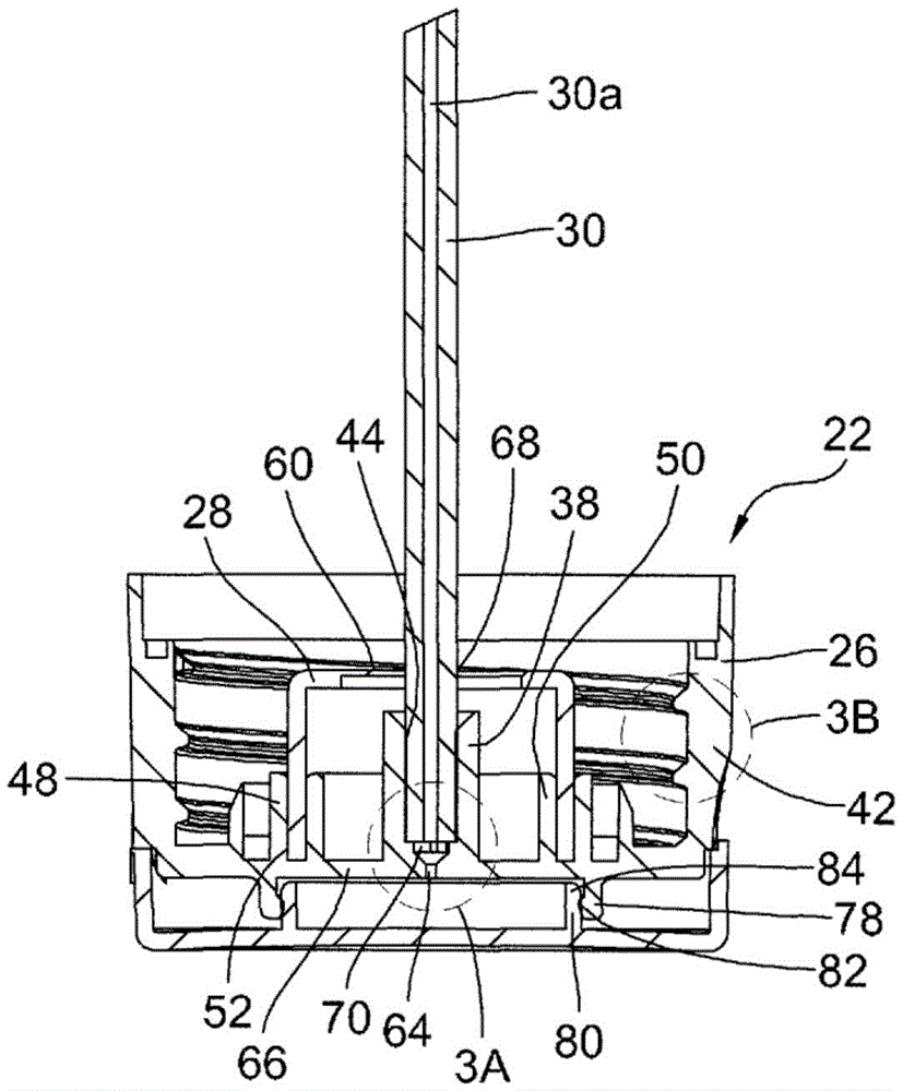
FIG. 3 is a front elevational view, in full section, of a squeeze emitter closure in a closed condition comprising a portion of the inverted squeeze emitter of FIG. 1.
Fig. 3A is an enlarged detail of the chamber of the squeeze emitter closure of fig. 3, wherein the chamber opens into the dispensing outlet.
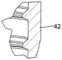
Fig. 3B is an enlarged detail of the threaded wall of the squeeze emitter closure of fig. 3.
Fig. 4 is an exploded view of the squeeze sprayer closure of fig. 3 turned to an upright orientation.
Fig. 5 is a front view of a flip top cap including a portion of the squeeze sprayer closure of fig. 3 with the cap hinged open.
Fig. 6 is a right side view of the flip top cap of fig. 5.
Fig. 7 is a left side view of the flip top cap of fig. 5.
Fig. 8 is a rear view of the flip top cap of fig. 5.
Fig. 9 is a top view of the flip top cap of fig. 5.
FIG. 10 is a right side elevational view, in full section, of the squeeze emitter closure of FIG. 3 in the open state.
FIG. 11 is a front elevational view, in full section, of a valve including a portion of the squeeze emitter closure of FIG. 3.
Fig. 12 is a front elevational view, in full section, of a dip tube comprising a portion of the squeeze emitter closure of fig. 3.
Fig. 13 is a bottom plan view of the squeeze emitter closure of fig. 10 in an open state.
Fig. 14 is an enlarged detail of the chamber as part of the flip top cap.
Detailed Description
For the purposes of promoting an understanding of the principles of the invention, reference will now be made to the embodiments illustrated in the drawings and specific language will be used to describe the same. It will nevertheless be understood that no limitation of the scope of the invention is thereby intended. Any alterations and further modifications in the described embodiments, and any further applications of the principles of the invention as described herein are contemplated as would normally occur to one skilled in the art to which the invention relates. One embodiment of the invention is shown in great detail, but it will be apparent to those skilled in the relevant art that some features that are not relevant to the present invention may not be shown for the sake of clarity.
Referring to fig. 1 and 2, there is shown a squeeze sprayer 20 including an assembled combination of a squeeze sprayer closure 22 and a squeeze bottle 24. Squeeze sprayer closure 22 (see fig. 3, 3A, 3B and 4) includes a squeeze sprayer flip-top cap 26, a two-way diaphragm valve 28 and a dip tube 30. The intended use of squeeze sprayer 20 is preferably in an inverted position, as shown, with closure 22 positioned below bottle 24 (see fig. 1 and 2). In this inverted orientation, the inlet 32 of the dip tube 30 is above the liquid level 34, such that air is drawn into the dip tube 30 from the headspace of the bottle 24. Squeezing (manually squeezing) the sidewall 36 of the bottle 24 inwardly forces air through the dip tube 30 and forces liquid into the annular sleeve 38 of the flip top cap 26. Referring to FIG. 3, the particular flow path of the liquid when the bottle 24 is squeezed is between the inner surface of the annular sleeve 38 and the outer surface of the dip tube 30. In the exemplary embodiment, annular neck 40 of bottle 24 is externally threaded. Referring to fig. 3 and 3B, the inner surface of the annular outer wall 42 of the flip top cap 26 is internally threaded in a corresponding and mating manner. This mating thread configuration allows the flip top cap 26 to be threaded onto the bottle neck 40 for secure assembly of the flip top cap 26 and the bottle 24.
With continued reference to fig. 3, 3A, and 4, the component parts comprising the closure 22 are shown in an assembled view (fig. 3) and an exploded view (fig. 4). As described above, the closure 22 comprises an assembly of a flip-top cap 26, a two-way diaphragm valve 28, and a dip tube 30. The dip tube 30, which preferably has a substantially cylindrical form, is received within an annular sleeve 38 of the cap 26. A moderate level of interference fit is selected as the manner of maintaining the dip tube 30 in this assembled state within the sleeve 38. This interference fit is not required for the entire axial length of the sleeve 38, only enough of the interference fit area to hold the dip tube 30 in this retained position. However, as noted above, a liquid flow path needs to exist between the dip tube 30 and the sleeve 38. In the exemplary embodiment, this flow path is accomplished by providing one or more liquid flow passages 44 in the body of the sleeve 38 facing the dip tube 30. For purposes of the exemplary embodiment, two liquid flow channels 44 are provided. In an alternative form of the exemplary embodiment, four liquid flow passages 44 are provided.
The flip top cap 26 includes an annular inner wall 46 that is substantially concentric with the annular sleeve 38. The inner wall 46 includes an annular radially outer portion 48 and an annular radially inner portion 50 that together define an annular channel 52 therebetween. Preferably, cap 26 has a substantially cylindrical form, at least partially having major structural portions thereof, each of which is substantially cylindrical and substantially concentric, such that the axial centerline of cap 26 is the axial centerline 53 of sleeve 38 and inner wall 46.
The two-way diaphragm valve 28 has a substantially cylindrical form with an annular wall 54 and an annular, partially closed end 56 and an annular, open end 58. The open end 58 is inserted into the annular channel 52 by a moderate interference fit. This moderate interference fit is sufficient for the passage 52 to retain the valve 28 in this assembled state. The partially closed end 56 includes an intermediate panel 60 having a small guide hole 62 for receiving the dip tube 30. The panel 60 has a thickness less than the remainder of the closed end 56, thereby providing greater flexibility to the panel 60. The valve 28 is preferably a one-piece component made of an elastomeric material. Providing the wall 54 with an increased wall thickness as compared to the face plate 60 enables the end 58 to be sufficiently rigid to be inserted into the channel 52 with a moderate interference fit as previously described. The panel 60, while more flexible, allows it to flex and deflect (i.e., open) in response to increased pressure due to the squeeze bottle 24 in order to allow the flow of liquid. While the valve 28 could be made from two pieces, one for the more rigid body and one for the flexible panel, this would increase the number of component parts and logically may increase the overall cost.
When the dip tube 30 is pushed through the guide hole 60 to insert the dip tube 30 into the sleeve 38, the annular portion of the face plate 60 immediately surrounding the guide hole 62 bends and deflects in the direction of the sleeve 38. The annular portion is snugly disposed against the outer surface of dip tube 30. When there is an increase in internal pressure due to manually squeezing the bottle 24, air from the headspace of the inverted bottle is forced into the inlet 32 and travels to the dispensing outlet 64 defined by the panel 66 of the cap 26. At the same time, liquid from within the bottle 24 is forced against the panel 60. The deflecting annular lip 68 formed by the surrounding annular portion of the face plate 60 is slightly open, thereby forming a clearance flow path between the lip 68 and the outer surface of the dip tube 30. This flow of liquid eventually reaches the flow channels 44 (whether two channels in one embodiment or four channels in another embodiment) and flows into the chamber 70, the chamber 70 being located between the interior of the sleeve 38 and the dispensing outlet 64. Once the pressure is released, such that liquid flow is complete, the annular lip 68 returns to its sealed condition against the dip tube 30. This quick closure prevents any suck back and slows down any dripping.
The flip top cap 26 is preferably a one-piece molded plastic component. Therefore, there is no particular line representing the boundary line between the sleeve 38 and the panel 66. For purposes of this disclosure, it is assumed that panel 66 has a substantially uniform thickness as it extends across interior portion 50. Thus, the dispensing outlet 64 is depicted as being defined by the face plate 66, and the chamber 70 is defined by the sleeve 38. The hollow interior 30a of the dip tube 30 opens directly into the chamber 70, and the chamber 70 opens directly into the dispensing outlet 64.
The chamber 70 is in liquid flow communication with the flow passage 44 such that both air and liquid flow together before the combination exits through the outlet 64 as a spray mist under pressure conditions. Referring to fig. 3A and 14, it can be seen that as liquid flows through the channels 44 to the chamber 70, there is a flow path extension 72 along the end from each channel 44. Each flow passage extension 72 creates a partial circular liquid flow rotation around the end opening of the dip tube 30. The combination of the liquid flow rotation and the high velocity air flow all within the chamber 70 creates a spray mist distribution from the dispensing outlet 64 that occurs quickly when the bottle 24 is manually squeezed.
The cap 26 includes a hinged cover 74 as part of its single-piece construction that is constructed and arranged to cover the panel 66 and close the outlet 64. Living hinge 76 is used to connect cover 74 to the remainder of cap 26. The fixing of the cover 74 on the rest of the cap 26 and its closed state is achieved by a snap-fit fitting. The face plate 66 includes an annular wall extension 78 and the cover 74 includes a mating annular wall 80. The wall extension 78 includes a small annular rib 82 on its inner surface. Since the snap-fit closure of the lid 74 is based on the snap fit between the mating annular ribs 82 and 84 as shown in fig. 3, the wall 80 includes a mating annular rib 84 on its outer surface.
While exemplary embodiments of the present invention have been disclosed and described as inverted squeeze sprayers, it is important to note that the disclosed configuration may be used at an inverted angle. The use of an inverted angle may be something that is beneficial as an alternative to shaping the bottle as part of a different geometry. For example, if the bottle is more ergonomic at an angle, it is possible to use the disclosed squeeze sprayer at an inverted angle.
It is also technically possible to use the disclosed squeeze jet in an upright position, although it is contemplated that the properties of the resulting spray mist may not meet all commercial requirements or desires. From a technical point of view, upright use reverses the gas flow path and the liquid flow path. While the two components still converge in the chamber 70, the high velocity of the gas stream in the exemplary embodiment helps to produce the desired spray mist. When the two flows are reversed, instead of having high velocity air, there will be high velocity liquid. When liquid is delivered through the dip tube and the air stream is swirled in the chamber 70, the nature of the spray mist will be different, but may be acceptable for limited use.
While the invention has been illustrated and described in detail in the drawings and foregoing description, the same is to be considered as illustrative and not restrictive in character, it being understood that only the preferred embodiment has been shown and described and that all changes, equivalents, and modifications that come within the spirit of the invention as defined by the following claims are desired to be protected. All publications, patents, and patent applications cited in this specification are herein incorporated by reference as if each individual publication, patent, or patent application were specifically and individually indicated to be incorporated by reference and set forth in its entirety herein.

Claims (8)

1.一种用于分配作为喷射雾的液体产品的倒置的挤压喷射器,所述挤压喷射器包括:1. An inverted squeeze sprayer for dispensing a liquid product as a spray mist, the squeeze sprayer comprising: 挤压瓶;squeeze bottle; 挤压喷射器帽,其由所述挤压瓶接收并且限定用于接收空气和液体的室与出口,所述挤压喷射器帽具有包括环形套管的单件构造;a squeeze spray cap received by the squeeze bottle and defining a chamber and an outlet for receiving air and liquid, the squeeze spray cap having a one-piece construction including an annular sleeve; 双通隔膜阀,其组装到所述挤压喷射器帽中,所述双通隔膜阀具有圆柱形的形式,其具有环形壁和环形的部分闭合端及环形敞开端;以及A two-way diaphragm valve assembled into the squeeze injector cap, the two-way diaphragm valve having a cylindrical form having an annular wall and an annular partially closed end and an annular open end; and 汲取管,其由所述挤压喷射器帽的环形套管接收,所述双通隔膜阀包括具有所述汲取管延伸通过的孔的柔性面板,并且其使所述汲取管与可偏转环形唇部接合,所述汲取管向所述室提供空气,其中,挤压所述瓶迫使空气通过所述汲取管进入到所述室中,并迫使液体通过所述环形套管的内表面与所述汲取管的外表面之间的流动路径进入到所述室中,并且然后作为喷射雾通过所述出口。a dip tube that is received by the annular sleeve of the squeeze injector cap, the two-way diaphragm valve includes a flexible panel having a hole through which the dip tube extends, and which couples the dip tube to a deflectable annular lip The diptube provides air to the chamber, wherein squeezing the bottle forces air through the diptube into the chamber and forces liquid through the inner surface of the annular sleeve and the chamber The flow path between the outer surfaces of the diptube enters the chamber and then passes through the outlet as a spray mist. 2.根据权利要求1所述的倒置的挤压喷射器,其中,所述环形套管限定所述室。2. The inverted squeeze injector of claim 1, wherein the annular sleeve defines the chamber. 3.根据权利要求1所述的倒置的挤压喷射器,其中,所述挤压喷射器帽包括限定所述出口的面板。3. The inverted squeeze sprayer of claim 1, wherein the squeeze spray cap includes a panel defining the outlet. 4.根据权利要求3所述的倒置的挤压喷射器,其中,所述挤压喷射器帽包括作为所述单件构造的一部分的翻转顶盖。4. The inverted squeeze sprayer of claim 3, wherein the squeeze sprayer cap includes a flip top cap as part of the one-piece construction. 5.根据权利要求1所述的倒置的挤压喷射器,其中,所述挤压喷射器帽包括作为所述单件构造的一部分的翻转顶盖。5. The inverted squeeze sprayer of claim 1, wherein the squeeze spray cap includes a flip top cap as part of the one-piece construction. 6.根据权利要求1所述的倒置的挤压喷射器,其中,所述挤压喷射器帽限定位于所述挤压喷射器帽的一部分与所述汲取管之间的液体流动通道。6. The inverted squeeze jet of claim 1, wherein the squeeze jet cap defines a liquid flow passage between a portion of the squeeze jet cap and the dip tube. 7.根据权利要求6所述的倒置的挤压喷射器,其中,所述室与所述液体流动通道流体流动连通。7. The inverted squeeze injector of claim 6, wherein the chamber is in fluid flow communication with the liquid flow channel. 8.根据权利要求7所述的倒置的挤压喷射器,其中,所述室构造且布置为限定与所述液体流动通道液体流动连通的流动通路延伸部。8. The inverted squeeze injector of claim 7, wherein the chamber is constructed and arranged to define a flow passage extension in liquid flow communication with the liquid flow channel.
CN201780037559.3A 2016-04-15 2017-04-04 Squeeze sprayer closure Active CN109414713B (en)

Applications Claiming Priority (3)

Application Number Priority Date Filing Date Title
US201662323025P 2016-04-15 2016-04-15
US62/323,025 2016-04-15
PCT/EP2017/057929 WO2017178274A1 (en) 2016-04-15 2017-04-04 Squeeze sprayer closure

Publications (2)

Publication Number Publication Date
CN109414713A CN109414713A (en) 2019-03-01
CN109414713B true CN109414713B (en) 2022-06-03

Family

ID=58489005

Family Applications (1)

Application Number Title Priority Date Filing Date
CN201780037559.3A Active CN109414713B (en) 2016-04-15 2017-04-04 Squeeze sprayer closure

Country Status (4)

Country Link
US (1) US20190160480A1 (en)
EP (1) EP3442715B1 (en)
CN (1) CN109414713B (en)
WO (1) WO2017178274A1 (en)

Families Citing this family (5)

* Cited by examiner, † Cited by third party
Publication number Priority date Publication date Assignee Title
US10973387B2 (en) 2015-06-26 2021-04-13 Unger Marketing International, Llc Multi-orientation cleaning device
WO2018053170A1 (en) 2016-09-14 2018-03-22 Unger Marketing International, Llc Hard surface cleaning devices
USD911844S1 (en) 2019-01-18 2021-03-02 Unger Marketing International, Llc Bottle for a cleaning device
WO2021055067A1 (en) * 2019-09-20 2021-03-25 H.J. Heinz Company Brands Llc Container, closure, and methods for manufacture
WO2022109236A1 (en) 2020-11-19 2022-05-27 Rieke Llc Squeeze foamer with low profile closure and drip resistant vent

Citations (2)

* Cited by examiner, † Cited by third party
Publication number Priority date Publication date Assignee Title
US4093124A (en) * 1976-07-26 1978-06-06 L'oreal Atomizer with air inlet valve
WO2014016427A1 (en) * 2012-07-27 2014-01-30 Twist Beauty Packaging Airspray N.V. System for dispensing a foam of a fluid product

Family Cites Families (7)

* Cited by examiner, † Cited by third party
Publication number Priority date Publication date Assignee Title
FR1275938A (en) * 1960-12-12 1961-11-10 Finaplax S A Holding Spray liquid dispenser
FR1447591A (en) * 1964-09-24 1966-07-29 Werner & Mertz Gmbh Spray head for bottle made of elastic synthetic material
US3493179A (en) * 1968-01-12 1970-02-03 Tsu Hsuen Lee Squeeze bottle
US3710989A (en) * 1969-11-06 1973-01-16 Monsanto Co Spray dispensing cap and hinged closure
FR2320142A1 (en) * 1975-08-04 1977-03-04 Oreal VAPORIZER BOTTLE WITH AIR INTAKE VALVE
US4186882A (en) * 1977-12-08 1980-02-05 Harry Szczepanski Atomizing liquid dispenser
IT1307523B1 (en) * 1999-12-02 2001-11-06 Taplast Spa METHOD OF DISPENSING LIQUIDS IN THE FORM OF FOAM THROUGH DEFORMABLE CONTAINERS AND DEVICE USING SUCH METHOD

Patent Citations (2)

* Cited by examiner, † Cited by third party
Publication number Priority date Publication date Assignee Title
US4093124A (en) * 1976-07-26 1978-06-06 L'oreal Atomizer with air inlet valve
WO2014016427A1 (en) * 2012-07-27 2014-01-30 Twist Beauty Packaging Airspray N.V. System for dispensing a foam of a fluid product

Also Published As

Publication number Publication date
US20190160480A1 (en) 2019-05-30
EP3442715A1 (en) 2019-02-20
CN109414713A (en) 2019-03-01
WO2017178274A1 (en) 2017-10-19
EP3442715B1 (en) 2020-09-30

Similar Documents

Publication Publication Date Title
CN109414713B (en) Squeeze sprayer closure
CN107405638B (en) Pump dispenser with outlet valve
CN100572218C (en) Dispensers with Elastomer Drain Valves
AU2009230810B2 (en) Dome pump spray assembly
JP2006517860A (en) Improvements regarding distribution nozzles
JP2015531726A (en) Inverted squeeze former
WO2005005055A1 (en) Nozzle arrangements
JP2004132356A (en) Pump dispenser with improved discharge valve
JP4877623B2 (en) Compressed bottle sprayer supply head, squeeze bottle sprayer, bottle with spray supply
US10919063B2 (en) Squeeze sprayer for fluid products
US5687877A (en) Pump dispenser having moveable outlet check valve element
US6676029B2 (en) Stream straightener for fluid flowing and dispensing nozzle
JP2012501825A (en) Fluid dispenser device
CN112218726B (en) Trigger sprayer without metal parts
CN110650809B (en) Spraying device and manufacturing method thereof
AU2001245655A1 (en) Method of using a dispensing head for a squeeze dispenser
US20170173599A1 (en) Modular Nozzle Assembly and Fluidic Plate Apparatus and Method for Selectively Creating 2-D or 3-D Spray Patterns
US20140054324A1 (en) Upright squeeze foamer
JP2015532625A (en) Upright squeeze former

Legal Events

Date Code Title Description
PB01 Publication
PB01 Publication
SE01 Entry into force of request for substantive examination
GR01 Patent grant
GR01 Patent grant