CN109204269B - Brake pedal simulators, car braking systems and vehicles - Google Patents
Brake pedal simulators, car braking systems and vehicles Download PDFInfo
- Publication number
- CN109204269B CN109204269B CN201710525671.3A CN201710525671A CN109204269B CN 109204269 B CN109204269 B CN 109204269B CN 201710525671 A CN201710525671 A CN 201710525671A CN 109204269 B CN109204269 B CN 109204269B
- Authority
- CN
- China
- Prior art keywords
- elastic member
- brake pedal
- rack
- thrust
- axial direction
- Prior art date
- Legal status (The legal status is an assumption and is not a legal conclusion. Google has not performed a legal analysis and makes no representation as to the accuracy of the status listed.)
- Active
Links
Images




Classifications
-
- B—PERFORMING OPERATIONS; TRANSPORTING
- B60—VEHICLES IN GENERAL
- B60T—VEHICLE BRAKE CONTROL SYSTEMS OR PARTS THEREOF; BRAKE CONTROL SYSTEMS OR PARTS THEREOF, IN GENERAL; ARRANGEMENT OF BRAKING ELEMENTS ON VEHICLES IN GENERAL; PORTABLE DEVICES FOR PREVENTING UNWANTED MOVEMENT OF VEHICLES; VEHICLE MODIFICATIONS TO FACILITATE COOLING OF BRAKES
- B60T8/00—Arrangements for adjusting wheel-braking force to meet varying vehicular or ground-surface conditions, e.g. limiting or varying distribution of braking force
- B60T8/32—Arrangements for adjusting wheel-braking force to meet varying vehicular or ground-surface conditions, e.g. limiting or varying distribution of braking force responsive to a speed condition, e.g. acceleration or deceleration
- B60T8/34—Arrangements for adjusting wheel-braking force to meet varying vehicular or ground-surface conditions, e.g. limiting or varying distribution of braking force responsive to a speed condition, e.g. acceleration or deceleration having a fluid pressure regulator responsive to a speed condition
- B60T8/40—Arrangements for adjusting wheel-braking force to meet varying vehicular or ground-surface conditions, e.g. limiting or varying distribution of braking force responsive to a speed condition, e.g. acceleration or deceleration having a fluid pressure regulator responsive to a speed condition comprising an additional fluid circuit including fluid pressurising means for modifying the pressure of the braking fluid, e.g. including wheel driven pumps for detecting a speed condition, or pumps which are controlled by means independent of the braking system
- B60T8/4072—Systems in which a driver input signal is used as a control signal for the additional fluid circuit which is normally used for braking
- B60T8/4081—Systems with stroke simulating devices for driver input
-
- B—PERFORMING OPERATIONS; TRANSPORTING
- B60—VEHICLES IN GENERAL
- B60T—VEHICLE BRAKE CONTROL SYSTEMS OR PARTS THEREOF; BRAKE CONTROL SYSTEMS OR PARTS THEREOF, IN GENERAL; ARRANGEMENT OF BRAKING ELEMENTS ON VEHICLES IN GENERAL; PORTABLE DEVICES FOR PREVENTING UNWANTED MOVEMENT OF VEHICLES; VEHICLE MODIFICATIONS TO FACILITATE COOLING OF BRAKES
- B60T7/00—Brake-action initiating means
- B60T7/02—Brake-action initiating means for personal initiation
- B60T7/04—Brake-action initiating means for personal initiation foot actuated
- B60T7/042—Brake-action initiating means for personal initiation foot actuated by electrical means, e.g. using travel or force sensors
-
- B—PERFORMING OPERATIONS; TRANSPORTING
- B60—VEHICLES IN GENERAL
- B60T—VEHICLE BRAKE CONTROL SYSTEMS OR PARTS THEREOF; BRAKE CONTROL SYSTEMS OR PARTS THEREOF, IN GENERAL; ARRANGEMENT OF BRAKING ELEMENTS ON VEHICLES IN GENERAL; PORTABLE DEVICES FOR PREVENTING UNWANTED MOVEMENT OF VEHICLES; VEHICLE MODIFICATIONS TO FACILITATE COOLING OF BRAKES
- B60T8/00—Arrangements for adjusting wheel-braking force to meet varying vehicular or ground-surface conditions, e.g. limiting or varying distribution of braking force
- B60T8/32—Arrangements for adjusting wheel-braking force to meet varying vehicular or ground-surface conditions, e.g. limiting or varying distribution of braking force responsive to a speed condition, e.g. acceleration or deceleration
- B60T8/34—Arrangements for adjusting wheel-braking force to meet varying vehicular or ground-surface conditions, e.g. limiting or varying distribution of braking force responsive to a speed condition, e.g. acceleration or deceleration having a fluid pressure regulator responsive to a speed condition
- B60T8/40—Arrangements for adjusting wheel-braking force to meet varying vehicular or ground-surface conditions, e.g. limiting or varying distribution of braking force responsive to a speed condition, e.g. acceleration or deceleration having a fluid pressure regulator responsive to a speed condition comprising an additional fluid circuit including fluid pressurising means for modifying the pressure of the braking fluid, e.g. including wheel driven pumps for detecting a speed condition, or pumps which are controlled by means independent of the braking system
- B60T8/4072—Systems in which a driver input signal is used as a control signal for the additional fluid circuit which is normally used for braking
- B60T8/4081—Systems with stroke simulating devices for driver input
- B60T8/409—Systems with stroke simulating devices for driver input characterised by details of the stroke simulating device
Landscapes
- Engineering & Computer Science (AREA)
- Physics & Mathematics (AREA)
- Fluid Mechanics (AREA)
- Transportation (AREA)
- Mechanical Engineering (AREA)
- Braking Elements And Transmission Devices (AREA)
- Braking Systems And Boosters (AREA)
Abstract
本公开涉及一种制动踏板模拟器、汽车制动系统和车辆,制动踏板模拟器包括制动踏板、助力电机、用于装配到车身上的装配部、沿轴向布置在装配部的一侧且沿轴向至少部分相互重叠的第一弹性件和第二弹性件、铰接于制动踏板并与第一弹性件和第二弹性件相互重叠部分的一端配合以能够驱动第一弹性件和第二弹性件同时沿轴向伸缩的推力结构,第一弹性件和第二弹性件共同配合而为制动踏板提供踏板预置力,助力电机的输出轴通过齿轮齿条机构与第一弹性件和第二弹性件相互重叠部分的一端配合,以能够为推力结构提供助力。由此提供可靠的制动踏板的制动感觉而模拟出准确的制动踏板力,具有操作稳定性良好、制动踏板相应迅速等效果。

The present disclosure relates to a brake pedal simulator, an automobile braking system and a vehicle. The brake pedal simulator includes a brake pedal, a booster motor, a fitting part for fitting to a vehicle body, and a fitting part arranged in the axial direction. The first elastic member and the second elastic member which are at least partially overlapped with each other in the axial direction are hinged to the brake pedal and cooperate with one end of the overlapping portion of the first elastic member and the second elastic member to be able to drive the first elastic member and the second elastic member. A thrust structure in which the second elastic member extends and retracts in the axial direction at the same time. The first elastic member and the second elastic member cooperate together to provide a pedal preset force for the brake pedal. The output shaft of the booster motor is connected to the first elastic member through a rack and pinion mechanism. It is matched with one end of the overlapping portion of the second elastic member, so as to be able to provide assistance for the thrust structure. Therefore, a reliable braking feeling of the brake pedal is provided to simulate an accurate brake pedal force, and the operation stability is good, and the brake pedal responds quickly and the like.
Description
技术领域technical field
本公开涉及车辆制动系统技术领域,具体地,涉及一种制动踏板模拟器、汽车制动系统和车辆。The present disclosure relates to the technical field of vehicle braking systems, and in particular, to a brake pedal simulator, a vehicle braking system and a vehicle.
背景技术Background technique
现有车辆特别是在电动汽车中,部分制动系统取消了传统制动系统的制动踏板与制动器之间的液压或机械连接,使驾驶员无法直接感知制动时反馈到制动踏板上的制动反力,从而丧失了传统制动系统的制动感觉。其中,制动感觉是指包括踏板制动感觉、驾驶员感受到的车辆制动减速度、听觉上的制动噪音以及视觉上的车辆减速度等诸多因素的综合感觉,其中,踏板制动感觉为最重要的部分。对于上述制动系统中通常通过增设制动踏板模拟器来模拟制动踏板的特性,从而为驾驶员提供良好的踏板制动感觉。制动踏板模拟器的工作原理为踏板力的设计目标是通过机械制动元件和某种控制方法来模拟制动踏板特性,例如,现有中通过机械制动元件和液压控制方法来实现。而采用这种液压控制方法的踏板模拟器不仅结构复杂而且因液压系统的液压冲击可能会导致模拟踏板力波动较大进而存在操作稳定性低下的问题。In existing vehicles, especially in electric vehicles, part of the braking system cancels the hydraulic or mechanical connection between the brake pedal and the brake of the traditional braking system, so that the driver cannot directly perceive the feedback to the brake pedal when braking. Braking reaction force, thereby losing the braking feel of traditional braking systems. Among them, the braking feeling refers to the comprehensive feeling of many factors including the pedal braking feeling, the vehicle braking deceleration felt by the driver, the audible braking noise, and the visual vehicle deceleration, among which, the pedal braking feeling for the most important part. For the above-mentioned braking system, a brake pedal simulator is usually added to simulate the characteristics of the brake pedal, so as to provide the driver with a good pedal braking feeling. The working principle of the brake pedal simulator is that the design goal of the pedal force is to simulate the characteristics of the brake pedal through a mechanical braking element and a certain control method. The pedal simulator using this hydraulic control method not only has a complex structure, but also has the problem of low operation stability due to the large fluctuation of the simulated pedal force due to the hydraulic shock of the hydraulic system.
发明内容SUMMARY OF THE INVENTION
本公开的目的是提供一种结构简单且操作稳定性良好的制动踏板模拟器、包括该制动踏板模拟器的汽车制动系统和车辆。An object of the present disclosure is to provide a brake pedal simulator with a simple structure and good operational stability, an automobile braking system and a vehicle including the brake pedal simulator.
为了实现上述目的,根据本公开的一个方面,提供一种制动踏板模拟器,该制动踏板模拟器包括制动踏板、助力电机、用于装配到车身上的装配部、沿轴向布置在所述装配部的一侧且沿所述轴向至少部分相互重叠的第一弹性件和第二弹性件、铰接于所述制动踏板并与所述第一弹性件和所述第二弹性件相互重叠部分的一端配合以能够驱动所述第一弹性件和所述第二弹性件同时沿所述轴向伸缩的推力结构,所述第一弹性件和所述第二弹性件共同配合而为所述制动踏板提供踏板预置力,所述助力电机的输出轴通过齿轮齿条机构与所述第一弹性件和所述第二弹性件相互重叠部分的所述一端配合,以能够为所述推力结构提供助力。In order to achieve the above object, according to one aspect of the present disclosure, there is provided a brake pedal simulator, the brake pedal simulator including a brake pedal, a booster motor, a fitting portion for fitting to a vehicle body, and an axially arranged A first elastic piece and a second elastic piece which at least partially overlap each other along the axial direction on one side of the assembling portion, are hinged to the brake pedal and are connected with the first elastic piece and the second elastic piece One end of the overlapping parts is matched to be able to drive the first elastic member and the second elastic member to expand and contract along the axial direction at the same time, and the first elastic member and the second elastic member cooperate together to form The brake pedal provides a pedal preset force, and the output shaft of the booster motor cooperates with the one end of the overlapping portion of the first elastic member and the second elastic member through a rack and pinion mechanism, so as to be able to The thrust structure provides assistance.
可选地,所述第一弹性件和所述第二弹性件为螺旋弹簧。Optionally, the first elastic member and the second elastic member are coil springs.
可选地,所述第一弹性件的延伸长度在所述轴向上小于所述第二弹性件的延伸长度,且所述第一弹性件和所述第二弹性件相互重叠部分的所述一端在所述轴向上对齐。Optionally, the extension length of the first elastic member is smaller than the extension length of the second elastic member in the axial direction, and the first elastic member and the second elastic member overlap each other in the portion of the One end is aligned in the axial direction.
可选地,所述第一弹性件的尺寸小于第二弹性件的尺寸,且所述第一弹性件位于所述第二弹性件的内部。Optionally, the size of the first elastic member is smaller than that of the second elastic member, and the first elastic member is located inside the second elastic member.
可选地,所述第一弹性件和所述第二弹性件相互重叠部分的所述一端通过第一弹簧座与所述推力结构配合,所述齿轮齿条机构的齿条的第一端与所述第一弹簧座连接或抵接,所述第二弹性件的另一端上设置有第二弹簧座,所述第一弹性件的另一端支撑在所述第二弹簧座上,所述第一弹簧座能够相对于所述第二弹簧座沿所述轴向移动。Optionally, the one end of the overlapping portion of the first elastic member and the second elastic member is matched with the thrust structure through a first spring seat, and the first end of the rack of the rack-and-pinion mechanism is connected to the thrust structure. The first spring seat is connected or abutted, the other end of the second elastic member is provided with a second spring seat, the other end of the first elastic member is supported on the second spring seat, the first elastic member is A spring seat is movable in the axial direction relative to the second spring seat.
可选地,所述第一弹簧座包括第一凸缘和从该第一凸缘沿所述轴向延伸的第一延伸杆,所述齿条的所述第一端抵接于所述第一凸缘,所述第二弹簧座包括第二凸缘和从该第二凸缘沿所述轴向延伸的第二延伸杆,所述第一延伸杆沿所述轴向可移动地套设在所述第二延伸杆内,所述第一弹性件设置在所述第一凸缘和所述第二延伸杆之间的位置,所述第二弹性件设置在所述第一凸缘和所述第二凸缘之间的位置。Optionally, the first spring seat includes a first flange and a first extension rod extending in the axial direction from the first flange, and the first end of the rack is abutted against the first flange. a flange, the second spring seat includes a second flange and a second extension rod extending from the second flange along the axial direction, the first extension rod is movably sleeved along the axial direction In the second extension rod, the first elastic member is disposed between the first flange and the second extension rod, and the second elastic member is disposed between the first flange and the second extension rod. the position between the second flanges.
可选地,所述推力结构包括铰接于所述制动踏板的第一推力杆和铰接于该第一推力杆并能够驱动所述第一弹簧座沿所述轴向移动的第二推力杆,该第二推力杆与所述齿条的第二端配合。Optionally, the thrust structure includes a first thrust rod hinged to the brake pedal and a second thrust rod hinged to the first thrust rod and capable of driving the first spring seat to move along the axial direction, The second thrust rod is engaged with the second end of the rack.
可选地,所述齿条的所述第一端形成有与所述第一弹簧座抵接的第一配合凸缘,所述第二端形成有与所述第二推力杆配合的第二配合凸缘。Optionally, the first end of the rack is formed with a first matching flange abutting against the first spring seat, and the second end is formed with a second matching flange with the second thrust rod mating flange.
可选地,所述第二推力杆形成为球头螺栓,该第二推力杆的球头与所述第二配合凸缘弧面配合。Optionally, the second thrust rod is formed as a ball stud, and the ball head of the second thrust rod is matched with the arc surface of the second matching flange.
可选地,所述球头的曲率半径小于所述第二配合凸缘的弧形配合面的曲率半径。Optionally, the radius of curvature of the ball head is smaller than the radius of curvature of the arc-shaped mating surface of the second mating flange.
可选地,所述第二推力杆的铰接端设置有与该铰接端螺纹连接的U形的铰接座,该铰接座的两侧板上分别形成有铰接孔,所述第二推力杆贯通所述铰接座的底板并通过设置在所述底板上的螺母螺纹连接在该底板上以能够沿轴向调整位置。Optionally, the hinged end of the second thrust rod is provided with a U-shaped hinged seat threadedly connected to the hinged end, and hinged holes are respectively formed on the two side plates of the hinged seat, and the second thrust rod penetrates through the hinged end. The bottom plate of the hinge seat is threadedly connected to the bottom plate through a nut arranged on the bottom plate, so that the position can be adjusted in the axial direction.
可选地,所述齿轮齿条机构包括齿轮轴和齿条,所述齿轮轴与所述助力电机的输出轴连接且设置有与所述齿条啮合的助力齿轮,所述齿条的第一端与所述第一弹性件和所述第二弹性件相互重叠部分的所述一端配合,所述齿条的第二端与所述推力结构配合。Optionally, the rack-and-pinion mechanism includes a pinion shaft and a rack, the pinion shaft is connected to the output shaft of the booster motor and is provided with a booster gear that meshes with the rack, the first gear of the rack is The end is matched with the one end of the overlapping portion of the first elastic member and the second elastic member, and the second end of the rack is matched with the thrust structure.
可选地,所述助力电机的输出轴通过减速机构与所述齿轮轴连接。Optionally, the output shaft of the booster motor is connected to the gear shaft through a reduction mechanism.
可选地,所述减速机构为行星轮减速机构,该行星轮减速机构中,太阳轮与所述助力电机的输出轴连接,行星架与所述齿轮轴连接,齿圈固定于所述制动踏板模拟器的壳体内。Optionally, the deceleration mechanism is a planetary gear deceleration mechanism. In the planetary gear deceleration mechanism, the sun gear is connected to the output shaft of the booster motor, the planet carrier is connected to the gear shaft, and the ring gear is fixed to the brake. inside the housing of the pedal simulator.
可选地,所述助力电机、所述减速机构以及所述齿轮齿条机构位于所述装配部对应于所述第一弹性件和所述第二弹性件的一侧。Optionally, the booster motor, the deceleration mechanism and the rack-and-pinion mechanism are located on a side of the fitting portion corresponding to the first elastic member and the second elastic member.
可选地,所述装配部靠近所述齿轮齿条机构的齿条的一侧设置有用于检测所述齿条的位移的位移传感器。Optionally, a displacement sensor for detecting the displacement of the rack is provided on a side of the assembling portion close to the rack of the rack-and-pinion mechanism.
可选地,所述制动踏板模拟器还包括用于控制所述助力电机的工作状态的控制器以及用于检测所述助力电机的转速的传感器。Optionally, the brake pedal simulator further includes a controller for controlling the working state of the booster motor and a sensor for detecting the rotational speed of the booster motor.
根据本公开的另一方面,提供一种汽车制动系统,所述汽车制动系统包括如上所述的制动踏板模拟器。According to another aspect of the present disclosure, there is provided an automobile braking system including the brake pedal simulator as described above.
可选地,所述汽车制动系统包括制动控制单元,该制动控制单元根据所述制动踏板的实时制动踏板力或踏板行程控制所述助力电机的工作状态。Optionally, the automobile braking system includes a brake control unit, which controls the working state of the booster motor according to the real-time brake pedal force or pedal stroke of the brake pedal.
根据本公开的又一方面,提供一种车辆,该车辆包括如上所述的汽车制动系统。According to yet another aspect of the present disclosure, there is provided a vehicle including the vehicle braking system as described above.
通过如上所述的结构,在驾驶员踩下制动踏板时,推力结构驱动第一弹性件和第二弹性件同时沿轴向压缩,推力结构受到第一弹性件和第二弹性件共同配合提供的反向作用力,而当这种反向作用力作用于制动踏板的制动踏板力达到预设值时,助力电机被启动使得其输出转矩通过齿轮齿条机构转化为驱动第一弹性件和第二弹性件沿轴向压缩的力而为制动踏板和推力结构提供助力。具体地,齿轮齿条机构驱动第一弹性件和第二弹性件的至少相互重叠部分的一端沿轴向同步地进行压缩,使得制动踏板和推力结构进一步发生位移变化,并且由于齿轮齿条机构承受由第一弹性件和第二弹性件提供的一部分反向作用力,由此能够降低推力结构受到的反向作用力,使得制动踏板获得合适的制动踏板力,由此能够模拟出转的制动踏板力,具有操作稳定性良好、制动踏板响应迅速等效果。在此,当助力电机、齿轮齿条机构、第一弹性件或第二弹性件等部件发生故障而无法正常工作时,通过未发生故障的第一弹性件和/或第二弹性件为制动踏板提供基础踏板力而也能够实现制动踏板的制动感觉,从而能够继续实施制动,保证制动系统始终保持正常工作,保持制动功能。Through the above structure, when the driver depresses the brake pedal, the thrust structure drives the first elastic member and the second elastic member to compress in the axial direction at the same time, and the thrust structure is provided by the first elastic member and the second elastic member in cooperation with each other. When the brake pedal force of this reverse force acting on the brake pedal reaches the preset value, the booster motor is activated so that its output torque is converted into driving the first elastic force through the rack and pinion mechanism The brake pedal and the thrust structure are assisted by the force of axial compression of the member and the second elastic member. Specifically, the rack and pinion mechanism drives at least one end of the overlapping portion of the first elastic member and the second elastic member to synchronously compress in the axial direction, so that the brake pedal and the thrust structure are further changed in displacement, and due to the rack and pinion mechanism Bearing a part of the reverse force provided by the first elastic member and the second elastic member, the reverse force received by the thrust structure can be reduced, so that the brake pedal can obtain a suitable brake pedal force, so that the rotation can be simulated. The high brake pedal force has the effect of good operation stability and quick response of the brake pedal. Here, when components such as the booster motor, the rack-and-pinion mechanism, the first elastic member or the second elastic member fail to work normally, the first elastic member and/or the second elastic member that does not fail to act as a brake The pedal provides the basic pedal force and can also realize the braking feeling of the brake pedal, so that the braking can be continued, ensuring that the braking system always keeps working normally and maintaining the braking function.
本公开的其他特征和优点将在随后的具体实施方式部分予以详细说明。Other features and advantages of the present disclosure will be described in detail in the detailed description that follows.
附图说明Description of drawings
附图是用来提供对本公开的进一步理解,并且构成说明书的一部分,与下面的具体实施方式一起用于解释本公开,但并不构成对本公开的限制。在附图中:The accompanying drawings are used to provide a further understanding of the present disclosure, and constitute a part of the specification, and together with the following detailed description, are used to explain the present disclosure, but not to limit the present disclosure. In the attached image:
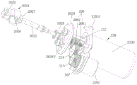
图1为根据本公开第一实施方式的制动踏板模拟器的结构原理示意图;FIG. 1 is a schematic diagram of the structural principle of a brake pedal simulator according to a first embodiment of the present disclosure;
图2为根据本公开第一实施方式的制动踏板模拟器中第二推力杆和对接头的配合状态图;FIG. 2 is a state diagram of the mating state of the second thrust rod and the butt joint in the brake pedal simulator according to the first embodiment of the present disclosure;
图3为根据本公开第一实施方式的制动踏板模拟器的装配图二,其中省去了制动踏板和第一推力杆;3 is a second assembly view of the brake pedal simulator according to the first embodiment of the present disclosure, wherein the brake pedal and the first thrust rod are omitted;
图4为根据本公开第一实施方式的制动踏板模拟器的装配图三,其中省去了制动踏板和第一推力杆;4 is a third assembly view of the brake pedal simulator according to the first embodiment of the present disclosure, wherein the brake pedal and the first thrust rod are omitted;
图5为根据本公开第一实施方式的制动踏板模拟器中推力结构和壳体的装配图,其中省略了制动踏板和第一推力杆;5 is an assembly view of the thrust structure and the housing in the brake pedal simulator according to the first embodiment of the present disclosure, wherein the brake pedal and the first thrust rod are omitted;
图6为根据本公开第二实施方式的制动踏板模拟器的结构原理示意图;FIG. 6 is a schematic diagram of the structural principle of the brake pedal simulator according to the second embodiment of the present disclosure;
图7为根据本公开第二实施方式的制动踏板模拟器中第二推力杆和对接头的配合状态图;7 is a state diagram of the mating state of the second thrust rod and the butt joint in the brake pedal simulator according to the second embodiment of the present disclosure;
图8为根据本公开第二实施方式的制动踏板模拟器的装配图一,其中省去了制动踏板和第一推力杆;8 is an assembly drawing 1 of the brake pedal simulator according to the second embodiment of the present disclosure, wherein the brake pedal and the first thrust rod are omitted;
图9为根据本公开第二实施方式的制动踏板模拟器的装配图二,其中省去了制动踏板第一推力杆、第一弹性件、第二弹性件以及部分弹簧座的结构;9 is a second assembly view of the brake pedal simulator according to the second embodiment of the present disclosure, wherein the structures of the first thrust rod of the brake pedal, the first elastic member, the second elastic member and part of the spring seat are omitted;
图10为根据本公开第二实施方式的制动踏板模拟器中推力结构和壳体的装配图,其中省略了制动踏板和第一推力杆;10 is an assembly view of a thrust structure and a housing in a brake pedal simulator according to a second embodiment of the present disclosure, wherein the brake pedal and the first thrust rod are omitted;
图11为根据本公开第二实施方式的制动踏板模拟器在第一工作状态下的结构原理示意图;FIG. 11 is a schematic structural principle diagram of the brake pedal simulator according to the second embodiment of the present disclosure in a first working state;
图12为根据本公开第三实施方式的制动踏板模拟器的结构原理示意图;FIG. 12 is a schematic diagram of the structural principle of the brake pedal simulator according to the third embodiment of the present disclosure;
图13为根据本公开第三实施方式的制动踏板模拟器的第二推力杆的结构图;13 is a structural diagram of a second thrust rod of a brake pedal simulator according to a third embodiment of the present disclosure;
图14为根据本公开第三实施方式的制动踏板模拟器的推力结构和壳体的装配图一,其中省去了第一推力杆;14 is an assembly view 1 of the thrust structure and the housing of the brake pedal simulator according to the third embodiment of the present disclosure, wherein the first thrust rod is omitted;
图15为根据本公开第三实施方式的制动踏板模拟器的推力结构和壳体的装配图二,其中省去了第一推力杆;15 is a second assembly view of the thrust structure and the housing of the brake pedal simulator according to the third embodiment of the present disclosure, wherein the first thrust rod is omitted;
图16为根据本公开第四实施方式的制动踏板模拟器的结构原理示意图;FIG. 16 is a schematic diagram of the structural principle of the brake pedal simulator according to the fourth embodiment of the present disclosure;
图17为根据本公开第四实施方式的制动踏板模拟器的第二推力杆的结构图;17 is a structural diagram of a second thrust rod of a brake pedal simulator according to a fourth embodiment of the present disclosure;
图18为根据本公开第四实施方式的制动踏板模拟器的推力结构和壳体的装配图一,其中省去了第一推力杆;18 is an assembly view 1 of the thrust structure and the housing of the brake pedal simulator according to the fourth embodiment of the present disclosure, wherein the first thrust rod is omitted;
图19为根据本公开第四实施方式的制动踏板模拟器的推力结构和壳体的装配图二,其中省去了第一推力杆。19 is a second assembly view of the thrust structure and the housing of the brake pedal simulator according to the fourth embodiment of the present disclosure, in which the first thrust rod is omitted.
附图标记说明Description of reference numerals
100、200、300、400制动踏板;101、201、301、401助力电机;102、202、302、402推力结构;103、203、303、403第一弹性件;104、204、304、404第二弹性件;105、205、305、405装配部;106、206螺旋机构;306、406齿轮齿条机构;107、207行星轮减速机构;307、407齿轮副减速机构;108、208、308、408控制器;109、209、309、409传感器;110、210、310、410第一弹簧座;111、211、311、411第二弹簧座;112、212连杆;115、215、312、412第一凸缘;113、213传动齿轮;117、217、313、413第一延伸杆;114、214惰轮;116、216、314、414第二凸缘;;118、218、315、415第二延伸杆;316、416第一配合凸缘;317、417第二配合凸缘;318、418位移传感器;119、219抵接弹簧座;120、220、320、420壳体;1011、2011、3011、4011输出轴;1021、2021、3021、4021第一推力杆;1022、2022、3022、4022第二推力杆;1023、2023、3023、4023、球头;1024、2024、3024、4024铰接座;1025、2025、3025、4025铰接孔;1026、2026、3026、4026底板;1027、2027、3027、4027螺母;1028、2028对接头;3028、4028卡止座;1029、2029推盘;3029、4029卡止突起;1051、2051、3051、4051紧固件;1061、2061助力螺杆;3061、4061齿轮轴;1062、2062、3063、4063助力齿轮;3062、4062齿条;1071、2071、3071、4071太阳轮;1072、2072、3072、4072行星架;1073、2073、3073、4073齿圈;1074、2074、3074、4074行星轮;3101、4101卡止凹槽;1201、2201、3201、4201第一壳体部;1202、2202、3202、4202第二壳体部;1203、2203、3203、4203第三壳体部;1204、2204、3204、4204防尘罩;10281、20281U形压板;3181、4181安装孔。100, 200, 300, 400 brake pedal; 101, 201, 301, 401 booster motor; 102, 202, 302, 402 thrust structure; 103, 203, 303, 403 first elastic piece; 104, 204, 304, 404 105, 205, 305, 405 assembly part; 106, 206 screw mechanism; 306, 406 rack and pinion mechanism; 107, 207 planetary gear reduction mechanism; 307, 407 gear pair reduction mechanism; 108, 208, 308 , 408 controller; 109, 209, 309, 409 sensor; 110, 210, 310, 410 first spring seat; 111, 211, 311, 411 second spring seat; 112, 212 connecting rod; 115, 215, 312, 412 first flange; 113, 213 transmission gear; 117, 217, 313, 413 first extension rod; 114, 214 idler; 116, 216, 314, 414 second flange;; 118, 218, 315, 415 316, 416 first mating flange; 317, 417 second mating flange; 318, 418 displacement sensor; 119, 219 abutting spring seat; 120, 220, 320, 420 housing; , 3011, 4011 output shaft; 1021, 2021, 3021, 4021 first thrust rod; 1022, 2022, 3022, 4022 second thrust rod; 1023, 2023, 3023, 4023, ball head; 1024, 2024, 3024, 4024 hinged 1025, 2025, 3025, 4025 hinge hole; 1026, 2026, 3026, 4026 bottom plate; 1027, 2027, 3027, 4027 nut; 1028, 2028 butt joint; 3028, 4028 snap seat; , 4029 locking protrusion; 1051, 2051, 3051, 4051 fasteners; 1061, 2061 booster screw; 3061, 4061 gear shaft; 1062, 2062, 3063, 4063 booster gear; 3062, 4062 rack; 1071, 2071, 3071 , 4071 sun gear; 1072, 2072, 3072, 4072 planet carrier; 1073, 2073, 3073, 4073 ring gear; 1074, 2074, 3074, 4074 planetary gear; 3101, 4101 locking groove; 1201, 2201, 3201, 4201 The first housing part; 1202, 2202, 3202, 4202 the second housing part; 1203, 2203, 3203, 4203 the third housing part; 1204, 2204, 3204, 4204 dust cover; , 4181 mounting holes.
具体实施方式Detailed ways
以下结合附图对本公开的具体实施方式进行详细说明。应当理解的是,此处所描述的具体实施方式仅用于说明和解释本公开,并不用于限制本公开。The specific embodiments of the present disclosure will be described in detail below with reference to the accompanying drawings. It should be understood that the specific embodiments described herein are only used to illustrate and explain the present disclosure, but not to limit the present disclosure.
在本公开中,在未作相反说明的情况下,使用的方位词如“内、外”通常是指相应部件轮廓的内、外。In the present disclosure, where not stated to the contrary, the use of directional words such as "inside, outside" generally refers to the inside and outside of the contour of the corresponding component.
如图1至图19所示,本公开提供一种制动踏板模拟器、汽车制动系统以及车辆的技术方案。本公开的制动踏板模拟器通过弹性件和制动方法来实现模拟制动踏板特性,在此,制动踏板特性通常是通过踏板力和踏板行程以及制动响应时间三者之间的对应关系来体现。As shown in FIG. 1 to FIG. 19 , the present disclosure provides a brake pedal simulator, a vehicle braking system, and a technical solution for a vehicle. The brake pedal simulator of the present disclosure simulates the characteristics of the brake pedal through the elastic element and the braking method. Here, the characteristics of the brake pedal are usually the corresponding relationship between the pedal force, the pedal stroke and the braking response time. to manifest.
本公开的制动踏板模拟器采用了多个弹性件和用于驱动多个弹性件沿轴向伸缩的推力结构的配合结构,具体地,根据本公开的第一至第七实施方式,通过如下技术方案来实现:根据本公开的制动踏板模拟器包括制动踏板、多个弹性件以及铰接于所述制动踏板并与多个所述弹性件配合以用于驱动所述弹性件沿轴向伸缩的推力结构,多个所述弹性件中的至少部分弹性件为所述制动踏板提供所述踏板预置力。在此,踏板预置力通常是指在未踩下制动踏板的初始状态下,制动踏板通过经由推力结构受到由弹性件施加的反作用力。其中,所有弹性件或者部分弹性件为制动踏板提供踏板力,保证制动系统始终保持正常工作而能够提供可靠的制动踏板的制动感觉,由此通过如上所述的简单结构就能够模拟出准确的制动踏板力,且具有操作稳定性良好、制动踏板相应迅速等效果。另外,对于制动踏板的踏板行程可以间接地通过控制推力结构的移动行程或者弹性件的压缩行程等的方式来确定,或者也可以通过其他合理地控制方式来控制制动踏板的踏板行程,在此并不特别限定。The brake pedal simulator of the present disclosure adopts a plurality of elastic members and a matching structure of a thrust structure for driving the plurality of elastic members to expand and contract in the axial direction. Specifically, according to the first to seventh embodiments of the present disclosure, the following The technical solution is to achieve: the brake pedal simulator according to the present disclosure includes a brake pedal, a plurality of elastic members, and is hinged to the brake pedal and cooperates with the plurality of the elastic members for driving the elastic members along a shaft To the telescopic thrust structure, at least a part of the elastic members of the plurality of elastic members provide the brake pedal with the pedal preset force. Here, the pedal preset force generally refers to the reaction force exerted by the elastic member on the brake pedal through the thrust structure in the initial state when the brake pedal is not depressed. Wherein, all or part of the elastic members provide pedal force for the brake pedal to ensure that the braking system always works normally and can provide a reliable braking feeling of the brake pedal. Therefore, the simple structure as described above can simulate Accurate brake pedal force is produced, and the operation stability is good, and the brake pedal responds quickly. In addition, the pedal stroke of the brake pedal can be determined indirectly by controlling the movement stroke of the thrust structure or the compression stroke of the elastic member, or can also be controlled by other reasonable control methods. This is not particularly limited.
另外,本公开中所提及的配合通常可以解释为通过直接或间接连接、固定、抵接或其他配合方式而能够实现动力传递的功能,在此并不特别作限定。In addition, the cooperation mentioned in the present disclosure can generally be interpreted as a function of realizing power transmission through direct or indirect connection, fixation, abutment or other cooperation methods, which is not particularly limited herein.
此外,多个弹性件可以根据实际需要即安装空间、操作稳定性等不同需求来合理地设计多个弹性件的布置位置、相互布置关系。可选地,多个所述弹性件中的部分弹性件为所述制动踏板提供所述踏板预置力的情况下,所述推力结构能够按照预定顺序驱动多个所述弹性件中的所述部分弹性件和其余弹性件沿所述轴向伸缩;多个所述弹性件均为所述制动踏板提供所述踏板预置力的情况下,所述推力结构能够驱动所有所述弹性件沿轴向同步伸缩。在此,对于多个弹性件中的部分弹性件为制动踏板提供踏板预置力的情况,可以通过所述多个弹性件中的所述部分弹性件在初始状态下(即未踩下制动踏板的状态)与推力结构配合,且多个弹性件中的其余弹性件在初始状态下不与推力结构和/或所述部分弹性件配合的方式来实现。在踩下制动踏板至预设踏板行程后,通过推力结构直接驱动其余弹性件或者推力结构通过所述部分弹性件来驱动其余弹性件等方式来实现驱动所述其余弹性件沿轴向伸缩的功能。在此,在其余弹性件被伸缩的过程中,所述部分弹性件也可以随所述其余弹性件同步地伸缩,或者所述部分弹性件也可以保持在被压缩的状态,对此可以根据实际需要来具体设计。另外,对于上述提及的按照预定顺序根据多个弹性件的具体布置方式来合理地设计。例如,在多个弹性件中的所述部分弹性件为两个以上且沿轴向依次相连布置,而其余弹性件为两个以上且沿轴向依次相连或间隔布置的情况下,所述按照预定顺序可以为推力结构先驱动所述部分弹性件压缩,在所述部分弹性件压缩至预设位置后,可以通过所述部分弹性件与所述其余弹性件接触的方式或者推力结构与所述其余弹性件配合的方式来使得推力结构依次驱动所述其余弹性件压缩。而对于从压缩状态转变为初始状态的顺序可以与如上所述的顺序相反。此外,再如,当所述部分弹性件为两个以上(在此可以采用相同尺寸的弹性件)且沿周向方向间隔布置(例如,可以在沿轴向间隔布置的两个圆盘等结构的支撑体之间布置沿所述两个支撑体的周向间隔布置的多个弹性件),而其余弹性件也为两个以上(在此可以采用相同尺寸的弹性件)且沿周向方向间隔布置(例如,可以在沿轴向间隔布置的两个圆盘等结构的支撑体之间布置沿所述两个支撑体的周向间隔布置的多个弹性件)的情况下,所述按照预定顺序可以为推力结构先共同驱动所述部分弹性件沿轴向压缩,在所述部分弹性件共同被压缩到预设位置后,可以通过所述部分弹性件与所述其余所有弹性件接触的方式或者推力结构与所述其余所有弹性件配合的方式来使得推力结构共同驱动所述其余所有弹性件沿轴向压缩。而对于从压缩状态转变为初始状态的顺序可以与如上所述的顺序相反。对于上述举例的对弹性件的具体驱动方式,本公开并不限定于此,只要能够通过推力结构的驱动最终能够实现驱动多个弹性件伸缩的功能,则可以采用其他多种适当的多个弹性件的布置方式,其均落到本公开的保护范围内。In addition, the arrangement positions and mutual arrangement relationships of the plurality of elastic elements can be reasonably designed according to actual needs, ie, different requirements such as installation space and operational stability. Optionally, when some of the plurality of elastic members provide the pedal preset force for the brake pedal, the thrust structure can drive all of the plurality of elastic members in a predetermined order. The part of the elastic members and the rest of the elastic members expand and contract along the axial direction; when a plurality of the elastic members provide the pedal preset force for the brake pedal, the thrust structure can drive all the elastic members Synchronous expansion and contraction along the axis. Here, in the case where a part of the elastic parts of the plurality of elastic parts provides a pedal preset force for the brake pedal, the part of the elastic parts of the plurality of elastic parts can be used in the initial state (that is, the brake pedal is not depressed) The state of the moving pedal) is matched with the thrust structure, and the remaining elastic pieces of the plurality of elastic pieces are not matched with the thrust structure and/or the partial elastic pieces in the initial state. After depressing the brake pedal to the preset pedal stroke, the thrust structure directly drives the remaining elastic members, or the thrust structure drives the remaining elastic members through the partial elastic members, etc., to realize the axial expansion and contraction of the remaining elastic members. Function. Here, in the process of the remaining elastic members being stretched and contracted, the partial elastic members can also be synchronously stretched and contracted with the remaining elastic members, or the partial elastic members can also be kept in a compressed state, which can be determined according to the actual situation. Specific design is required. In addition, according to the specific arrangement of the plurality of elastic members, the above-mentioned design can be reasonably designed according to the predetermined order. For example, in the case where there are two or more of the elastic members in the plurality of elastic members and are arranged in series in the axial direction, while the remaining elastic members are two or more and are successively connected in the axial direction or arranged at intervals, the The predetermined sequence may be that the thrust structure first drives the partial elastic member to compress, and after the partial elastic member is compressed to a preset position, the partial elastic member may be in contact with the remaining elastic members or the thrust structure may contact the elastic member. The other elastic members cooperate in such a way that the thrust structure sequentially drives the remaining elastic members to compress. The sequence for transitioning from the compressed state to the initial state may be reversed from that described above. In addition, for another example, when there are more than two elastic members (here, elastic members of the same size may be used) and they are arranged at intervals in the circumferential direction (for example, two discs and other structures may be arranged at intervals along the axial direction) A plurality of elastic pieces arranged at intervals along the circumferential direction of the two support bodies are arranged between the support bodies), and the remaining elastic pieces are also more than two (here, elastic pieces of the same size can be used) and are arranged along the circumferential direction. In the case of spaced arrangement (for example, a plurality of elastic members arranged at intervals along the circumferential direction of the two support bodies may be arranged between two support bodies of a structure such as a disk arranged at intervals in the axial direction), the The predetermined sequence may be that the thrust structure first jointly drives the partial elastic members to compress in the axial direction, and after the partial elastic members are jointly compressed to the preset position, the partial elastic members can be in contact with all the remaining elastic members through the contacting mechanism. The manner or the manner in which the thrust structure cooperates with all the remaining elastic members enables the thrust structure to jointly drive all the remaining elastic members to compress in the axial direction. The sequence for transitioning from the compressed state to the initial state may be reversed from that described above. As for the specific driving manner of the elastic members mentioned above, the present disclosure is not limited to this, as long as the function of driving multiple elastic members to expand and contract can be finally realized through the driving of the thrust structure, other suitable multiple elastic members can be adopted. The arrangement of the components falls within the protection scope of the present disclosure.
可选地,所述制动踏板模拟器包括用于驱动所述弹性件伸缩以能够为所述推力结构对于所述弹性件的驱动提供助力和/或阻力的驱动装置。在此,所述驱动装置可以采用多种适当的结构,其能够为推力结构对于弹性件的驱动提供助力、阻力或者可以同时满足提供助力和阻力的功能,由此能够通过驱动装置和推力结构的配合而能够更加精确地模拟出所需踏板力。在此,可选地,所述制动踏板模拟器包括用于驱动所述弹性件进一步伸缩以能够为所述推力结构对于所述弹性件的驱动提供助力的助力装置。其中,所述助力装置可以采用多种结构,例如可以为电动缸、气缸、液压缸等驱动缸、千斤顶等简单伸缩机构的单一结构,或者也可以为采用例如齿轮副、齿轮齿条副、涡轮蜗杆副、带传动副、螺旋副等多种机械传动机构相互传动配合的结构总成,无论采用哪种结构,在此并不限于上述提及的结构,只要能够实现为推力结构对于弹性件的驱动提供助力的功能即可。Optionally, the brake pedal simulator includes a driving device for driving the elastic member to extend and retract so as to provide the thrust structure with an assist and/or resistance for driving the elastic member. Here, the driving device can adopt various suitable structures, which can provide assistance and resistance for the driving of the elastic member by the thrust structure, or can satisfy the functions of providing assistance and resistance at the same time. It can more accurately simulate the required pedal force. Here, optionally, the brake pedal simulator includes a power assist device for driving the elastic member to further expand and contract so as to provide power for the driving of the elastic member by the thrust structure. Wherein, the power assisting device may adopt various structures, for example, it may be a single structure of a simple telescopic mechanism such as an electric cylinder, an air cylinder, a hydraulic cylinder, etc., a simple telescopic mechanism such as a jack, or may be a gear pair, a rack-and-pinion pair, a turbine, etc. No matter which structure is adopted, it is not limited to the structure mentioned above, as long as it can be realized as a thrust structure for elastic parts. It is enough to drive the function to provide assistance.
其中,可选地,所述助力装置包括助力电机、与该助力电机以及所述弹性件中的至少部分弹性件配合的传动配合机构,以能够通过该传动配合机构为所述推力结构的驱动提供助力。在本公开中,虽然提供了以下七种具体实施方式的制动踏板模拟器来模拟制动踏板特性,其中,为了便于且清楚地说明本公开,涉及的制动踏板100、200、300、400以及助力电机101、201、301、401均采用了相同的结构,但这并不用于限定本公开的权利范围。另外,对于传动配合机构可以采用多种合理的布置结构,只要能够实现将助力电机的输出转矩传递给弹性件以能够为推力结构提供助力的功能即可。例如,如图1至图11所示地,所述传动配合机构可以包括螺旋机构,助力电机的输出轴可以通过这种螺旋机构与弹性件配合,从而为推力结构对于弹性件的驱动提供助力。再如,如图12至图19所示,所述传动配合机构可以包括齿轮齿条机构,助力电机的输出轴可以通过这种齿轮齿条机构与弹性件配合,从而能够为推力结构对于弹性件的驱动提供助力。但本公开并不限定于上述结构,除上述结构之外,所述传动配合机构还可以为齿轮副传动机构、蜗轮蜗杆传动机构、带传动机构、链传动机构等多种结构,也可以为上述涉及到的多种结构之间的适当组合的结构。Wherein, optionally, the booster device includes a booster motor, a transmission and cooperation mechanism that cooperates with the booster motor and at least some of the elastic members, so that the driving of the thrust structure can be provided by the transmission and cooperation mechanism. help. In the present disclosure, although the following seven specific embodiments of the brake pedal simulator are provided to simulate the characteristics of the brake pedal, for the convenience and clarity of the present disclosure, the
具体地,在驾驶员踩下制动踏板时,推力结构驱动弹性件沿轴向压缩,推力结构受到弹性件提供的反向作用力,而当这种反向作用力作用于制动踏板的制动踏板力达到预设值时,启动助力电机使得由助力电机输出的转矩通过传动配合机构传递到弹性件,以能够为制动踏板和推力结构提供助力而驱动弹性件进一步被压缩,使得制动踏板和推力结构进一步发生位移变化,并且由于传动配合机构承受由弹性件施加的一部分反向作用力,由此能够降低推力结构受到的反向作用力,使得制动踏板获得合适的制动踏板力,从而能够模拟出制动踏板的踏板力和踏板行程的目标值。在此,当助力电机或传动配合机构发生故障而无法正常工作时,通过弹性件提供基础踏板力而也能够提供制动踏板的制动感觉,从而能够继续实施制动,保持制动功能。Specifically, when the driver steps on the brake pedal, the thrust structure drives the elastic member to compress in the axial direction, and the thrust structure is subjected to the reverse force provided by the elastic member, and when this reverse force acts on the brake pedal of the brake pedal When the power pedal force reaches the preset value, the booster motor is started so that the torque output by the booster motor is transmitted to the elastic member through the transmission matching mechanism, so as to provide power for the brake pedal and the thrust structure and drive the elastic member to be further compressed, so that the brake pedal is further compressed. The displacement of the moving pedal and the thrust structure is further changed, and since the transmission matching mechanism bears a part of the reverse force exerted by the elastic member, the reverse force on the thrust structure can be reduced, so that the brake pedal can obtain a suitable brake pedal. Therefore, the target value of the pedal force and pedal stroke of the brake pedal can be simulated. Here, when the booster motor or the transmission matching mechanism fails and cannot work normally, the basic pedal force can be provided by the elastic element to provide the braking feeling of the brake pedal, so that the braking can be continued and the braking function can be maintained.
通过如上所述地采用了助力电机和传动配合机构而为制动踏板对于弹性件的驱动提供助力,从而完善了弹性件的线性特性而实现了制动踏板的非线性变化特性。即,弹性件提供基础踏板反力,保证制动系统始终保持工作以在助力电机或传动配合机构等部件失效时也能够提供制动踏板的制动感觉,通过助力电机对于弹性件的驱动力来综合模拟踏板力,即通过助力电机和弹性件的配合而提供目标踏板力,以补偿基础踏板力和目标踏板力之间的剩余部分。由此,通过如上所述的制动控制方法来实现模拟制动踏板特性,并且通过助力电机和传动配合机构来替换如现有的液压制动部件而不仅结构简单且不会受到液压等因素的影响,从而具有操作稳定性良好、制动踏板响应迅速等效果。By adopting the booster motor and the transmission matching mechanism as described above, the brake pedal provides the booster for the driving of the elastic member, thereby improving the linear characteristic of the elastic member and realizing the nonlinear change characteristic of the brake pedal. That is, the elastic member provides the basic pedal reaction force to ensure that the braking system always keeps working so as to provide the braking feeling of the brake pedal even when components such as the booster motor or the transmission matching mechanism fail. The synthetically simulated pedal force, that is, the target pedal force is provided by the cooperation of the booster motor and the elastic member to compensate the remaining part between the base pedal force and the target pedal force. Therefore, the characteristics of the brake pedal are simulated by the braking control method as described above, and the existing hydraulic braking components are replaced by the booster motor and the transmission coordination mechanism, which is not only simple in structure, but also not affected by factors such as hydraulic pressure. Therefore, it has the effects of good operation stability and quick response of the brake pedal.
其中,在本公开的四种具体实施方式中,所述弹性件可以包括沿所述轴向布置的第一弹性件和第二弹性件,所述第一弹性件和/或所述第二弹性件共同配合而为所述制动踏板提供踏板预置力,所述传动配合机构与所述第一弹性件和/或所述第二弹性件配合。在此,对于弹性件的数量并不限定于两个弹性件,也可以根据实际情况来合理地选择。在此,采用了两个弹性件的形式,对于两个弹性件的布置方式可以采用如图1至图5、图12至图15所示的两个实施方式中公开的串联方式也可以采用如图6至图11、图16至图19所示的两个实施方式中公开的并联方式。在此,需要说明的是,串联方式是指两个弹性件沿轴向布置,且在通过推力结构和/或驱动电机的驱动下两个弹性件始终同时沿轴向伸缩,即,初始被驱动时两个弹性件同时被伸缩。具体地,在制动踏板和/或助力电机的驱动下,可以使得两个弹性件同步地进行压缩,并且在串联方式中制动踏板的踏板预置力可以由第一弹性件和第二弹性件的共同配合来提供;而并联方式是指两个弹性件沿轴向布置,且在推力结构和/或助力电机的驱动下两个弹性件件依次沿轴向伸缩,即初始被驱动时两个弹性件中的一者先实现沿轴向的压缩,之后另一者再进行沿轴向的伸缩。具体地,在制动踏板和/或助力电机的驱动下,可以使得在某一个弹性件在压缩的过程中与另一个弹性件相互接触而同时进一步压缩的布置方式,并且在并联方式中制动踏板的踏板预置力可以由第一弹性件或第二弹性件来提供,其中为制动踏板提供踏板预置力的弹性件最先被压缩。另外,对于两个弹性件的布置方式可以采用多种合理的结构,例如,两个弹性件采用串联布置结构的情况下,可以将两个弹性件沿轴向相邻布置,或者也可以采用至少部分重叠的布置方式。再如,两个弹性件采用并联布置结构的情况,可以将两个弹性件沿轴向间隔布置,或者也可以将两个弹性件沿轴向部分重叠的布置方式,对此本公开并不特别限定,可以根据实际需要例如空间布置需求等来具体设计弹性件的布置结构。上述说明中,为了更清楚地说明弹性件的布置方式,针对两个弹性件的布置结构进行了描述,但对于一个或两个以上的弹性件也均可以适用上述并联方式或串联方式。例如所述弹性件包括由多个第一弹性件沿周向间隔布置而并排的第一弹性单元和由多个第二弹性件沿周向间隔布置而并排的第二弹性单元。对于这种结构的弹性件也可以适用上述并联或串联方式。Wherein, in the four specific embodiments of the present disclosure, the elastic member may include a first elastic member and a second elastic member arranged along the axial direction, the first elastic member and/or the second elastic member The components cooperate together to provide a pedal preset force for the brake pedal, and the transmission cooperation mechanism cooperates with the first elastic member and/or the second elastic member. Here, the number of elastic members is not limited to two elastic members, and can also be reasonably selected according to the actual situation. Here, the form of two elastic members is adopted, and the arrangement of the two elastic members may adopt the serial mode disclosed in the two embodiments shown in FIG. 1 to FIG. 5 and FIG. 12 to FIG. The parallel mode disclosed in the two embodiments shown in FIGS. 6 to 11 and 16 to 19 . Here, it should be noted that the series connection means that the two elastic members are arranged in the axial direction, and the two elastic members always expand and contract in the axial direction at the same time under the driving of the thrust structure and/or the driving motor, that is, they are initially driven. When the two elastic members are stretched and contracted at the same time. Specifically, under the driving of the brake pedal and/or the booster motor, the two elastic members can be compressed synchronously, and the pedal preset force of the brake pedal can be controlled by the first elastic member and the second elastic member in the series mode. The parallel mode means that the two elastic members are arranged in the axial direction, and the two elastic members expand and contract along the axial direction in turn under the driving of the thrust structure and/or the booster motor, that is, when the two elastic members are initially driven One of the elastic members is compressed in the axial direction first, and then the other is expanded and contracted in the axial direction. Specifically, under the drive of the brake pedal and/or the booster motor, it is possible to make an arrangement in which a certain elastic piece is in contact with another elastic piece during the compression process and is further compressed at the same time, and the brake is applied in a parallel manner. The pedal preset force of the pedal may be provided by the first elastic member or the second elastic member, wherein the elastic member providing the pedal preset force for the brake pedal is compressed first. In addition, various reasonable structures may be adopted for the arrangement of the two elastic members. For example, when the two elastic members are arranged in series, the two elastic members may be arranged adjacent to each other in the axial direction, or at least Partially overlapping arrangement. For another example, in the case where the two elastic members are arranged in parallel, the two elastic members may be arranged at intervals along the axial direction, or the two elastic members may be partially overlapped along the axial direction, which is not particularly in the present disclosure. As a limitation, the arrangement structure of the elastic members can be specifically designed according to actual needs, such as space arrangement requirements. In the above description, in order to explain the arrangement of the elastic members more clearly, the arrangement structure of two elastic members is described, but the parallel mode or the series mode can also be applied to one or more than two elastic members. For example, the elastic member includes a plurality of first elastic members arranged at intervals in the circumferential direction and side by side, and a plurality of second elastic members arranged at a circumferential interval and side by side. The above-mentioned parallel or series connection can also be applied to the elastic element of this structure.
另外,可选地,所述传动配合机构包括螺旋机构或齿轮齿条机构,所述助力电机的输出轴通过所述螺旋机构或所述齿轮齿条机构与所述第一弹性件和所述第二弹性件配合,以能够驱动所述第一弹性件和所述第二弹性件同步地伸缩,或者所述助力电机的输出轴通过所述螺旋机构与所述第一弹性件或所述第二弹性件配合,以能够按照预定顺序驱动所述第一弹性件和所述第二弹性件沿所述轴向伸缩。即,如上所述地,在两个弹性件采用串联布置方式的情况下,助力电机的输出轴可以通过螺旋机构或齿轮齿条机构与第一弹性件和第二弹性件配合,通过助力电机输出的驱动力为推力结构提供助力,由此在通过推力结构驱动第一弹性件和第二弹性件被压缩的状态下,通过助力电机能够进一步驱动第一弹性件和第二弹性件同步被伸缩。在两个弹性件采用并联布置方式的情况下,助力电机的输出轴通过螺旋机构或齿轮齿条机构与第一弹性件或第二弹性件配合,从而通过助力电机输出的驱动力为推力结构提供助力,由此在通过推力结构驱动第一弹性件或第二弹性件被压缩的状态下,通过助力电机而能够进一步按照预定顺序驱动第一弹性件和/或第二弹性件沿轴向伸缩。在此,对于并联布置方式,当助力电机的输出轴通过螺旋机构或齿轮齿条机构与第一弹性件配合时,通过助力电机和传动配合机构先驱动第一弹性件伸缩后,通过第一弹性件与第二弹性件配合的方式或者传动配合机构后续与第二弹性件配合的方式来进一步驱动第二弹性件沿轴向伸缩;当助力电机的输出轴通过螺旋机构或齿轮齿条机构与第二弹性件配合时,通过助力电机和传动配合机构可以先驱动第二弹性件沿轴向伸缩后,再通过第二弹性件与第一弹性件配合的方式或者通过传动配合结构与第一弹性件直接配合的方式来进一步驱动第一弹性件沿轴向伸缩。针对上述助力电机和传动配合机构对于第一弹性件和第二弹性件的具体驱动顺序,本公开并不需要限定,其可以根据实际布置结构来合理地设计。In addition, optionally, the transmission matching mechanism includes a screw mechanism or a rack-and-pinion mechanism, and the output shaft of the power assist motor communicates with the first elastic member and the first elastic member through the screw mechanism or the rack-and-pinion mechanism. The two elastic members cooperate to be able to drive the first elastic member and the second elastic member to expand and contract synchronously, or the output shaft of the booster motor is connected to the first elastic member or the second elastic member through the screw mechanism. The elastic members cooperate to be able to drive the first elastic member and the second elastic member to expand and contract along the axial direction according to a predetermined sequence. That is, as mentioned above, when the two elastic members are arranged in series, the output shaft of the power assist motor can cooperate with the first elastic member and the second elastic member through the screw mechanism or the rack and pinion mechanism, and the output shaft of the power assist motor can output through the screw mechanism or the rack and pinion mechanism. The driving force provides boosting force for the thrust structure, so that the first elastic piece and the second elastic piece can be further driven by the booster motor to be expanded and contracted synchronously under the state that the thrust structure drives the first elastic piece and the second elastic piece to be compressed. When the two elastic members are arranged in parallel, the output shaft of the booster motor cooperates with the first elastic member or the second elastic member through a screw mechanism or a rack and pinion mechanism, so as to provide the thrust structure with the driving force output by the booster motor. As a result, when the first elastic member or the second elastic member is compressed by the thrust structure, the power assist motor can further drive the first elastic member and/or the second elastic member to expand and contract in the axial direction in a predetermined order. Here, for the parallel arrangement, when the output shaft of the booster motor cooperates with the first elastic member through the screw mechanism or the rack and pinion mechanism, the first elastic member is driven to expand and contract by the booster motor and the transmission matching mechanism, and then the first elastic member is driven to expand and contract by the first elastic member. The second elastic member is further driven to expand and contract in the axial direction by the way that the second elastic member cooperates with the second elastic member or the transmission matching mechanism cooperates with the second elastic member subsequently; When the two elastic members are matched, the second elastic member can be driven to expand and contract in the axial direction by the booster motor and the transmission matching mechanism, and then the second elastic member can be matched with the first elastic member or the transmission matching structure can be used with the first elastic member. The first elastic member is further driven to expand and contract in the axial direction by means of direct fit. The present disclosure does not need to limit the specific driving sequence of the first elastic member and the second elastic member by the booster motor and the transmission matching mechanism, which can be reasonably designed according to the actual arrangement structure.
此外,如上所述的制动踏板模拟器还可以包括用于装配到车身上的装配部,所述第一弹性件和所述第二弹性件可以布置在所述装配部的一侧。在此情况下,待制动踏板模拟器通过装配部装配到车辆时,位于装配部一侧的两个弹性件均位于发动机舱内。另外,但本公开并不限定于此,所述第一弹性件和第二弹性件可以根据实际空间布置需求来合理地设计布置位置,例如,第一弹性件和/或第二弹性件的部分结构可以位于装配部的另一侧,在此情况下,待制动踏板模拟器通过装配部装配到车辆时,位于所述装配部的所述另一侧的第一弹性件和/或第二弹性件的一部分可以位于发动机舱内,而另一部分可以露出于驾驶室,由此能够降低制动踏板模拟器在发动机舱内的占用空间。但本公开并不限定于此,对于弹性件的具体布置位置可以根据实际情况来合理地布置。In addition, the brake pedal simulator as described above may further include a fitting portion for fitting to the vehicle body, and the first elastic member and the second elastic member may be arranged on one side of the fitting portion. In this case, when the brake pedal simulator is to be fitted to the vehicle through the fitting portion, the two elastic members on one side of the fitting portion are both located in the engine compartment. In addition, but the present disclosure is not limited to this, the arrangement positions of the first elastic member and the second elastic member can be reasonably designed according to the actual space arrangement requirements, for example, the first elastic member and/or the part of the second elastic member The structure may be located on the other side of the fitting portion, in which case, when the brake pedal simulator is to be fitted to the vehicle through the fitting portion, the first elastic member and/or the second elastic member located on the other side of the fitting portion A part of the elastic member may be located in the engine compartment, and the other part may be exposed in the cab, thereby reducing the space occupied by the brake pedal simulator in the engine compartment. However, the present disclosure is not limited to this, and the specific arrangement position of the elastic member can be reasonably arranged according to the actual situation.
以下,针对图1至图19所示的四种实施方式进行具体说明,在此,图1至图5作为第一实施方式,图6至图11作为第二实施方式,图12至图15作为第三实施方式,图16至图19作为第四实施方式,其中,图1至图5所示的第一实施方式和图12至图15所示的第三实施方式中公开了第一弹性件和第二弹性件的串联布置的方式,图6至图11所示的第二实施方式和图16至图19所示的第四实施方式中公开了第一弹性件和第二弹性件的并联方式。Hereinafter, the four embodiments shown in FIGS. 1 to 19 will be described in detail. Here, FIGS. 1 to 5 are taken as the first embodiment, FIGS. 6 to 11 are taken as the second embodiment, and FIGS. 12 to 15 are taken as the first embodiment. The third embodiment, Figures 16 to 19 serve as the fourth embodiment, wherein the first elastic member is disclosed in the first embodiment shown in Figures 1 to 5 and the third embodiment shown in Figures 12 to 15 and the serial arrangement of the second elastic member, the second embodiment shown in FIGS. 6 to 11 and the fourth embodiment shown in FIGS. 16 to 19 disclose the parallel connection of the first elastic member and the second elastic member Way.
下面,首先对第一实施方式和第三实施方式的两个弹性件串联布置方式的技术方案进行说明。Below, the technical solution of the serial arrangement of the two elastic members in the first embodiment and the third embodiment will be described first.
参照图1至图5,根据本公开第一实施方式提供一种制动踏板模拟器,该制动踏板模拟器包括制动踏板100、助力电机101、用于装配到车身上的装配部105、沿轴向布置在所述装配部105的一侧且沿所述轴向至少部分相互重叠的第一弹性件103和第二弹性件104、铰接于所述制动踏板100并与所述第一弹性件103和所述第二弹性件103相互重叠部分的一端配合以能够驱动所述第一弹性件103和所述第二弹性件104同时沿所述轴向伸缩的推力结构102,所述第一弹性件103和所述第二弹性件104共同配合而为所述制动踏板100提供踏板预置力,所述助力电机101的输出轴1011通过螺旋机构106与所述第一弹性件103和所述第二弹性件104相互重叠部分的所述一端配合,以能够为所述推力结构102提供助力。1 to 5 , according to a first embodiment of the present disclosure, a brake pedal simulator is provided, the brake pedal simulator includes a brake pedal 100 , a
其中,第一弹性件103和第二弹性件104至少部分相互重叠部分的一端是指第一弹性件103和第二弹性件104的相互重叠部分的两者的相对应的一端,即,在第一弹性件103和第二弹性件104不管是部分相互重叠或者是全部相互重叠,所述相互重叠部分的一端是指第一弹性件103和第二弹性件104相对应布置的一端,其中,第一弹性件103和第二弹性件104的所述一端可以在轴向上齐平,或者也可以在轴向上间隔布置,在此,对于第一弹性件103和第二弹性件104的至少相互重叠部分的一端的布置结构并不特别限定,只要能够实现通过推力结构102和/或助力电机101驱动第一弹性件103和第二弹性件104沿轴向同步地压缩的功能即可。Wherein, one end of the overlapping portion of the first
在上述第一实施方式中,第一弹性件103和第二弹性件104作为制动踏板100的踏板力和踏板行程的模拟元件,在初始状态下(即未踩下制动踏板100的情况下),第一弹性件103和第二弹性件104均处于压缩状态以为制动踏板100提供踏板预置力,其中第一弹性件103和第二弹性件104中的一者失效的情况下其中另一者仍能够使得制动踏板100保持正常的踏板力,从而提高制动踏板模拟器的安全性能。In the above-mentioned first embodiment, the first
具体地,在驾驶员踩下制动踏板100时,推力结构102驱动第一弹性件103和第二弹性件104同时沿轴向压缩,推力结构102受到第一弹性件103和第二弹性件104共同配合提供的反向作用力,而当这种反向作用力作用于制动踏板100的制动踏板力达到预设值时,启动助力电机101使得其输出转矩通过螺旋机构106转化为驱动第一弹性件103和第二弹性件104沿轴向压缩的力而为制动踏板100和推力结构102提供助力,具体地,螺旋机构106驱动第一弹性件103和第二弹性件104的至少相互重叠部分的一端沿轴向同步地进行压缩,使得制动踏板100和推力结构102进一步发生位移变化,并且由于螺旋机构106承受由第一弹性件103和第二弹性件104提供的一部分反向作用力,由此能够降低推力结构102受到的反向作用力,使得制动踏板100获得合适的制动踏板力,从而能够模拟出制动踏板100的踏板力和踏板行程的目标值。在此,当助力电机101、螺旋机构106、第一弹性件103或第二弹性件104等部件发生故障而无法正常工作时,通过未发生故障的第一弹性件103和/或第二弹性件104为制动踏板100提供基础踏板力而也能够实现制动踏板100的制动感觉,从而能够继续实施制动,保持制动功能。另外,当驾驶员释放制动踏板100时,助力电机101失电而使得第一弹性件103和第二弹性件104由自身的弹性回复力而实现自动回位。通过如上所述的制动控制方法来实现模拟制动踏板100的特性,并且通过助力电机101和螺旋机构106的配合来替换现有的液压制动部件而使得制动踏板模拟器不仅结构简单且不会受到如现有中液压等多种因素的影响,从而具有操作稳定性良好、制动踏板响应迅速等效果。另外,虽然在本实施方式中传动配合机构采用了螺旋机构106,但本公开并不限定于此,所述传动配合机构可以采用其他合理的布置结构。Specifically, when the driver depresses the brake pedal 100 , the
可选地,所述第一弹性件103和所述第二弹性件104为螺旋弹簧。由此能够对由推力结构102和/或助力电机101作用的驱动力作出快速且灵敏的反应而伸缩。但这并不限定本公开的范围,在能够保证制动踏板100、助力电机101、推力结构102和螺旋机构106的配合来驱动第一弹性件103和第二弹性件104伸缩的情况下,所述第一弹性件103和第二弹性件104可以采用多种合理的结构。Optionally, the first
可选地,所述第一弹性件103的延伸长度在所述轴向上小于所述第二弹性件104的延伸长度,且所述第一弹性件103和所述第二弹性件104相互重叠部分的所述一端在所述轴向上对齐。在此,第一弹性件103和第二弹性件104的重叠部分的所述一端在轴向上对齐的情况下,第一弹性件103朝向第二弹性件104的延伸方向延伸,由此,整个第一弹性件103重叠在第二弹性件104的延伸部分上。由此,能够减少制动踏板模拟器的整体长度,且布置结构紧凑、使得制动踏板模拟器的整体结构体积最小化。但本公开并不限定于此,可以根据实际弹性刚度的需求来具体布置第一弹性件103和第二弹性件104的结构,例如,第一弹性件103和第二弹性件104可以形成为具有相同延伸长度的结构等。Optionally, the extension length of the first
其中,可选地,所述第一弹性件103的尺寸小于第二弹性件104的尺寸,且所述第一弹性件103位于所述第二弹性件104的内部。由此,能够使得推力结构102和/或助力电机101方便地驱动第一弹性件103和第二弹性件104沿轴向同步地压缩,同时还能够使得制动踏板模拟器的整体结构最小化。但本公开并不限定于此,可以根据实际需要来设计第一弹性件103和第二弹性件104的布置结构,例如,第一弹性件103的尺寸可以大于第二弹性件104的尺寸,并且第二弹性件104可以贯通布置在第一弹性件103的内部。Wherein, optionally, the size of the first
可选地,所述第一弹性件103和所述第二弹性件104相互重叠部分的所述一端通过第一弹簧座110与所述推力结构102配合,所述螺旋机构106与所述第一弹簧座110连接或抵接,所述第二弹性件104的另一端上设置有第二弹簧座111,所述第一弹性件103的另一端支撑在所述第二弹簧座111上,所述第一弹簧座110的所述一端能够相对于所述第二弹簧座111沿所述轴向移动。在此,可选地,如图1所示,所述第一弹簧座110可以包括第一凸缘115和从该第一凸缘115沿所述轴向延伸的第一延伸杆117,所述螺旋机构106的助力螺杆1061抵接于所述第一凸缘115,所述第二弹簧座111包括第二凸缘116和从该第二凸缘116沿所述轴向延伸的第二延伸杆118,所述第一延伸杆117沿所述轴向可移动地套设在所述第二延伸杆118内,所述第一弹性件103设置在所述第一凸缘115和所述第二延伸杆118之间的位置,所述第二弹性件104设置在所述第一凸缘115和所述第二凸缘116之间的位置。其中,第一弹性件103的延伸长度小于第二弹性件104的延伸长度,此时,第一弹性件103的另一端沿轴向抵接在第二弹簧座111的第二延伸杆118上,由此,通过推力结构102和/或助力电机101驱动第一弹簧座110压缩第一弹性件103和第二弹性件104的过程中,能够保证第一弹性件103和第二弹性件104同步地实现压缩。另外,当第一弹性件103的延伸长度和第二弹性件104的延伸长度相同且两者在轴向上完全重叠即第一弹性件103和第二弹性件104的两端在轴向上分别对齐的情况下,第一弹性件103的另一端可以直接抵接在第二弹簧座111的第二凸缘116上,而第二延伸杆118则位于第一弹性件103和第二弹性件104的内部并与第一延伸杆117可移动地连接。由此,通过合理的布置结构使得第一弹簧座110带动第一弹性件103和第二弹性件104相对于第二弹簧座111灵活地移动。但本公开并不限定于此,可以根据第一弹性件103和第二弹性件104的具体布置结构来合理地设计第一弹簧座110和第二弹簧座111的结构。例如,当第一弹性件103的延伸长度小于第二弹性件104的延伸长度且第一弹性件103与第二弹性件104的中部部分重叠的情况下,即,第一弹性件103的两端均位于第二弹性件104的两端之间的位置时,所述第一弹簧座110的第一凸缘115和第一延伸杆117之间还可以突出形成有台阶部以用于抵接第一弹性件103的一端,而第一弹性件103的另一端则可以抵接在第二弹簧座111的第二延伸杆118上。由此,也能够实现通过推力结构102和/或助力电机101驱动第一弹簧座110同时压缩第一弹性件103和第二弹性件104的功能。Optionally, the one end of the overlapping portion of the first
可选地,如图1至图4所示,所述第一弹簧座110对应于所述推力结构102的一端设置有沿所述轴向突出且沿周向间隔布置的多个连杆112,多个所述连杆112与所述推力结构102配合,所述螺旋机构106位于所述第一弹簧座110和所述推力结构102之间的位置。由此,使得助力电机101、螺旋机构106以及第一弹性件103和第二弹性件104之间的布置结构紧凑且便于实现模块化设计。但本公开并不限定于此,所述螺旋机构106可以布置在第二弹簧座111远离第一弹簧座110的一侧,并且螺旋机构106通过第一弹簧座111与第一弹性件103和第二弹性件104配合而能够沿轴向同步压缩的方向移动。由此,能够方便且易于实现螺旋机构106沿轴向同步地压缩第一弹性件103和第二弹性件104的功能。另外,对于第一弹簧座110的连杆112和推力结构102的配合形式可以采用多种结构,例如可以通过螺纹连接方式来实现。而在采用螺纹连接的方式的情况下,可以通过调整连杆112的螺纹连接部分的位置来调节制动踏板100的踏板预置力以及踏板空行程。但本公开并不限定于此,也可以通过采用其他方式连接第一弹簧座110和推力结构102。此外,多个连杆112也可以通过采用螺栓等紧固件而连接于第一弹簧座110,或者可以与第一弹簧座110直接形成为一体结构。Optionally, as shown in FIGS. 1 to 4 , one end of the
可选地,所述推力结构102包括铰接于所述制动踏板100的第一推力杆1021和通过铰接座1024铰接于该第一推力杆1021并能够驱动所述第一弹簧座110沿所述轴向移动的第二推力杆1022,所述铰接座1024形成为U形座,该铰接座1024的两侧板上分别形成有铰接孔1025,所述第二推力杆1022贯通所述铰接座1024的底板1026并通过设置在所述底板1026上的螺母1027螺纹连接在该底板1026上以能够沿轴向调整位置。其中,第二推力杆1022通过铰接座1024上的铰接孔1025与第一推力杆1021铰接,另外,通过底板1026上的螺母1027与第二推力杆1022螺纹配合而能够调整制动踏板100的踏板预置力和踏板空行程。但本公开并不限定于此,在此也可以通过其他形式来调整制动踏板100的踏板预置力和踏板空行程,例如,可以将第一推力杆1021或第二推力杆1022布置成能够沿轴向伸缩并定位的伸缩结构(例如可以为相互螺纹配合的套杆和套设在套杆外周面上的套管的结构)以通过伸缩的方式来调整踏板预置力和踏板空行程。再如,如上所述提及地,通过推力结构102和第一弹簧座110的连杆采用螺纹配合形式来实现调整踏板预置力和踏板空行程。而上述变形实施方式均可以适用于其他三种实施方式中。Optionally, the
可选地,所述第二推力杆1022形成为球头螺栓,所述推力结构102还包括与所述第二推力杆1022的球头1023球副连接的对接头1028,以及与所述第一弹簧座110连接且与所述对接头1028配合的推盘1029,所述螺旋机构106布置在所述推盘1029和所述第一弹性件103之间的位置上。其中,推盘1029可以位于装配部105的通孔内周面上,对接头1028可以贯穿推盘1029并通过螺母等紧固件定位,在此,可选地,所述推盘1029上形成有用于供所述对接头1028贯穿的通孔,所述对接头1028上形成有抵接于所述推盘1029靠近所述对接头1028的一侧的U形压板10281。由此,当对接头1028与推盘1029装配并定位后,U形压板10281抵接推盘1029对应于第二推力杆1022的一侧,从而能够通过U形压板10281稳定地推动推盘1029使得通过第一弹簧座110与该推盘1029连接的第一弹性件103和第二弹性件104沿轴向压缩。如上所述,在驾驶员踩下制动踏板100使其发生位移变化时,第一推力杆1021、第二推力杆1022、对接头1028、推盘1029也随之发生位移变化,而通过第二推力杆1022的球头1023与对接头1028的球副配合,能够使得第二推力杆1022适应角度变化,防止与对接头1023发生运动干涉现象。但本公开并不限定于此,在此还可选地,所述球头1023与对接头1028可以为弧面配合,且球头1023的曲率半径小于对接头1028对应于所述球头1023的弧形配合面的曲率半径。由此,在适当范围内允许第二推力杆1022的球头1023与对接头1028的弧形配合面发生相对运动而使得制动踏板100、推力结构102、第一弹性件103以及第二弹性件104之间的传动过程更为平滑。再如,第二推力杆1022与对接头1028可以采用万向节连接形式或者采用第二推力杆1022直接抵接于对接头1028的端面的形式。在此需要说明的是,对接头1028以及推盘1029的配合结构是为了能够更可靠地驱动第一弹性件103和第二弹性件104,而在能够实现上述目的的情况和不发生矛盾的情况下,可以对推力结构102的布置结构适当地进行变更,而这种变更均属于本公开的权利范围内。Optionally, the
可选地,所述助力电机101的输出轴1011通过传动机构与所述螺旋机构106连接。在此,传动机构可以采用多种合理的结构,以能够将助力电机101的输出转矩以适当的传动比传递给螺旋机构106,从而能够使得螺旋机构106可靠地驱动第一弹性件103和第二弹性件104沿轴向同步地压缩,进而快速且精确地模拟制动踏板100的踏板力和踏板行程。Optionally, the output shaft 1011 of the
可选地,所述传动机构包括与所述助力电机101的输出轴1011连接的减速机构、与该减速机构的输出端连接的传动齿轮113,所述螺旋机构106包括与所述第一弹性件103和第二弹性件104相互重叠部分的所述一端配合的助力螺杆1061,和安装在该助力螺杆1061的外周面上并形成有与所述助力螺杆1061螺纹配合的内螺纹的助力齿轮1062,所述传动齿轮113通过惰轮114与所述助力齿轮1062啮合。在此,助力螺杆1061可以直接连接或抵接于第一弹簧座110的形式与第一弹性件103和第二弹性件104配合,由此,助力电机101的输出转矩依次通过减速机构、传动齿轮113、助力齿轮1062而传递给助力螺杆1061,而助力螺杆1061的驱动力则通过第一弹簧座110传递给第一弹性件103和第二弹性件104,从而能够使得第一弹性件103和第二弹性件104沿轴向同步地压缩。Optionally, the transmission mechanism includes a reduction mechanism connected to the output shaft 1011 of the
在此,减速机构可以采用多种合理的结构,例如可以采用涡轮蜗杆减速机构、齿轮副减速机构或其他合理的结构,由此能够使得螺旋机构的助力齿轮1062获得适当的传动比而使得与该助力齿轮1062啮合的助力螺杆1061以适当的驱动力驱动第一弹性件103和第二弹性件104沿轴向压缩。可选地,所述传动配合机构还包括减速机构,所述助力电机101的输出轴1011通过所述减速机构与所述齿轮轴1061连接。在此,所述减速机构可以采用多种适当的结构,例如可以采用齿轮副减速机构、蜗轮蜗杆减速机构、行星轮减速机构等。在此,如图1所示,可选地,所述减速机构为行星轮减速机构107,该行星轮减速机构107中,太阳轮1071与所述助力电机101的输出轴1011连接,行星架1072作为所述减速机构的输出端而与所述传动齿轮113的轮轴连接,齿圈1073固定于所述制动踏板模拟器的壳体120内。在此,行星轮减速机构107中设置有与太阳轮1071和齿圈1073啮合的行星轮1074,行星轮1074的中心设置有行星架1072。由此,助力电机101的输出转矩经过该行星轮减速机构107减速增距后经由传动齿轮113、惰轮114、助力齿轮1062传递给助力螺杆1061。即,助力电机101的输出转矩经太阳轮1071、行星轮1074和行星架1072后,经由传动齿轮113、惰轮114以及助力齿轮1062传递给助力螺杆1061,使得助力螺杆1061沿轴向移动过程中驱动第一弹性件103和第二弹性件104同步地压缩。通过采用行星轮减速机构107,由于行星轮减速机构107本身具有重量轻且体积小的特点,从而使得制动踏板模拟器具有整体质量轻且布置紧凑。另外,通过设置行星轮减速机构107能够有效提高助力电机101的传动效率。Here, the deceleration mechanism can adopt various reasonable structures, for example, a worm gear deceleration mechanism, a gear pair deceleration mechanism or other reasonable structures can be adopted, so that the
可选地,所述制动踏板模拟器还包括用于控制所述助力电机101的工作状态的控制器108以及用于检测所述助力电机101的转速的传感器109。其中,传感器109可以设置在助力电机101的输出轴上,该传感器109电连接于控制器108。由此,在驾驶员踩下制动踏板100时,推力结构102驱动第一弹性件103和第二弹性件104同时沿轴向压缩,推力结构102受到第一弹性件103和第二弹性件104共同配合提供的反向作用力,而当这种反向作用力作用于制动踏板100的制动踏板力达到预设值时,控制器108控制启动助力电机101使得其输出转矩通过行星轮减速机构107和螺旋机构106传递到第一弹性件103和第二弹性件104而为制动踏板100和推力结构102提供助力,在此,通过螺旋机构106同步地驱动第一弹性件103和第二弹性件104沿轴向被压缩,使得制动踏板100和推力结构102进一步发生位移变化,并且由于螺旋机构106承受由第一弹性件103和第二弹性104共同配合而提供的一部分反向作用力,由此能够降低推力结构102受到的反向作用力,使得制动踏板100获得合适的制动踏板力,从而能够模拟出制动踏板100的踏板力和踏板行程的目标值。其中,传感器109用于实时检测助力电机101的转速并能够实时地反馈到控制器108以能够实时地监测到制动踏板100的踏板行程,由此能够提高制动踏板模拟器的工作可靠性。Optionally, the brake pedal simulator further includes a controller 108 for controlling the working state of the
可选地,如图5所示,所述制动踏板模拟器包括壳体120,该壳体120包括所述装配部105、用于容纳所述螺旋机构106(以及传动齿轮113和惰轮114)的第一壳体部1201、用于容纳所述助力电机101的第二壳体部1202以及用于容纳所述第一弹性件103和所述第二弹性件104的第三壳体部1203,所述第二弹性件104的端部抵接于第三壳体部1203的内端壁。其中,所述装配部105、第一壳体部1201、第二壳体部1202以及第三壳体部1203相互连通。第一壳体部1201、第二壳体部1202和第三壳体部1203可以通过螺栓等紧固件装配成一体。另外,所述第一壳体部1201上可以形成有用于向螺旋机构106以及传动机构提供润滑油的注油孔。此外,所述装配部105可以通过螺栓等紧固件1051装配到车身上,此时制动踏板100露出于驾驶室内,而推力结构102可以根据实际情况选择性地部分露出于驾驶室,以便于操作且使得制动踏板模拟器在在发动机舱内的所占安装空间较小。另外,在装配部105上可以设置有用于覆盖第二推力杆1022的部分外周面的防尘罩1204以起到密封和防尘的作用。通过如上所述的结构使得制动踏板模拟器具有布置紧凑且实现模块化设计的效果。但本公开并不限定于此,可以根据制动踏板模拟器的布置结构来合理地壳体120的结构。Optionally, as shown in FIG. 5 , the brake pedal simulator includes a
上述内容结合图1至图5介绍了第一实施方式中的制动踏板模拟器的结构,在不脱离本发明构思下,第一实施方式中的特征例如制动踏板结构、第一推力杆、第二推力杆等均可以应用于下述的其他实施方式中。以下参照附图12至图15,先对与上述第一实施方式中采用第一弹性件和第二弹性件的串联方式相同的布置结构的第三实施方式进行详细说明。The above content has introduced the structure of the brake pedal simulator in the first embodiment with reference to FIGS. 1 to 5 . Without departing from the concept of the present invention, the features of the first embodiment such as the structure of the brake pedal, the first thrust rod, the The second thrust rod and the like can be applied to other embodiments described below. Referring to FIGS. 12 to 15 , the third embodiment, which adopts the same arrangement structure as the first embodiment in the above-mentioned first embodiment, adopts the same series arrangement of the first elastic member and the second elastic member will be described in detail below.
如图12所示,根据本公开的第三具体实施方式提供一种制动踏板模拟器,该制动踏板模拟器包括制动踏板300、助力电机301、用于装配到车身上的装配部305、沿轴向布置在所述装配部305的一侧且沿所述轴向至少部分相互重叠的第一弹性件303和第二弹性件304、铰接于所述制动踏板300并与所述第一弹性件303和所述第二弹性件303相互重叠部分的一端配合以能够驱动所述第一弹性件303和所述第二弹性件304同时沿所述轴向伸缩的推力结构302,所述第一弹性件303和所述第二弹性件304共同配合而为所述制动踏板300提供踏板预置力,所述助力电机301的输出轴3011通过齿轮齿条机构306与所述第一弹性件303和所述第二弹性件304相互重叠部分的所述一端配合,以能够为所述推力结构302提供助力。其中,第一弹性件303和第二弹性件304作为制动踏板300的踏板力和踏板行程的模拟元件,在初始状态下(即未踩下制动踏板300的情况下),第一弹性件303和第二弹性件304均处于压缩状态以为制动踏板300提供踏板预置力,其中第一弹性件303和第二弹性件304中的一者失效的情况下其中另一者仍能够使得制动踏板300保持正常的踏板力,从而提高制动踏板模拟器的安全性能。As shown in FIG. 12 , according to a third embodiment of the present disclosure, a brake pedal simulator is provided, the brake pedal simulator includes a
具体地,在驾驶员踩下制动踏板300时,推力结构302驱动第一弹性件303和第二弹性件304同时沿轴向压缩,推力结构302受到第一弹性件303和第二弹性件304共同配合提供的反向作用力,而当这种反向作用力作用于制动踏板300的制动踏板力达到预设值时,启动助力电机301使得其输出转矩通过齿轮齿条机构306转化为驱动第一弹性件303和第二弹性件304沿轴向压缩的力而为制动踏板300和推力结构302提供助力,具体地,齿轮齿条机构306驱动第一弹性件303和第二弹性件304的至少相互重叠部分的一端沿轴向同步地进行压缩,使得制动踏板300和推力结构302进一步发生位移变化,并且由于齿轮齿条机构306承受由第一弹性件303和第二弹性件304提供的一部分反向作用力,由此能够降低推力结构302受到的反向作用力,使得制动踏板300获得合适的制动踏板力,从而能够模拟出制动踏板300的踏板力和踏板行程的目标值。在此,当助力电机301、齿轮齿条机构306、第一弹性件303或第二弹性件304等部件发生故障而无法正常工作时,通过未发生故障的第一弹性件303和/或第二弹性件304为制动踏板300提供基础踏板力而也能够实现制动踏板300的制动感觉,从而能够继续实施制动,保持制动功能。另外,当驾驶员释放制动踏板300时,助力电机301失电而使得第一弹性件303和第二弹性件304由自身的弹性回复力而实现自动回位。通过如上所述的制动控制方法来实现模拟制动踏板300的特性,并且通过助力电机301和齿轮齿条机构306的配合来替换现有的液压制动部件而使得制动踏板模拟器不仅结构简单且不会受到如现有中液压等多种因素的影响,从而具有操作稳定性良好、制动踏板响应迅速等效果。另外,虽然在本实施方式中传动配合机构采用了齿轮齿条机构306,但本公开并不限定于此,所述传动配合机构可以采用其他合理的布置结构。Specifically, when the driver depresses the
可选地,所述第一弹性件303和所述第二弹性件304为螺旋弹簧。由此能够对由推力结构302和/或助力电机301作用的驱动力作出快速且灵敏的反应而伸缩。但这并不限定本公开的范围,在能够保证制动踏板300、推力结构302、助力电机301和齿轮齿条机构306的配合来驱动第一弹性件303和第二弹性件304伸缩的情况下,所述第一弹性件303和第二弹性件304可以采用多种合理的结构。Optionally, the first
可选地,所述第一弹性件303的延伸长度在所述轴向上小于所述第二弹性件304的延伸长度,且所述第一弹性件303和所述第二弹性件304相互重叠部分的所述一端在所述轴向上对齐。上述技术特征和作用效果与第一实施方式中对应的技术特征和作用效果相同,在此为了避免重复,省略对其的详细说明。但本公开并不限定于此,可以根据实际弹性刚度的需求来具体布置第一弹性件303和第二弹性件304的结构,例如,第一弹性件303和第二弹性件304可以形成为具有相同延伸长度的结构等。Optionally, the extension length of the first
可选地,所述第一弹性件303的尺寸小于第二弹性件304的尺寸,且所述第一弹性件303位于所述第二弹性件304的内部。由此,能够使得推力结构302和/或助力电机301方便地驱动第一弹性件303和第二弹性件304沿轴向同步地压缩,同时还能够使得制动踏板模拟器的整体结构最小化。但本公开并不限定于此,可以根据实际需要来设计第一弹性件303和第二弹性件304的布置结构,例如,第一弹性件303的尺寸可以大于第二弹性件304的尺寸,并且第二弹性件304可以贯通布置在第一弹性件303的内部。Optionally, the size of the first
可选地,所述第一弹性件303和所述第二弹性件304相互重叠部分的所述一端通过第一弹簧座310与所述推力结构302配合,所述齿轮齿条机构306的齿条3062的第一端与所述第一弹簧座310连接或抵接,所述第二弹性件304的另一端上设置有第二弹簧座311,所述第一弹性件303的另一端支撑在所述第二弹簧座311上,所述第一弹簧座310的所述一端能够相对于所述第二弹簧座311沿所述轴向移动。在此,可选地,所述第一弹簧座310包括第一凸缘312和从该第一凸缘312沿所述轴向延伸的第一延伸杆313,所述齿条3062的所述第一端抵接于所述第一凸缘312,所述第二弹簧座311包括第二凸缘314和从该第二凸缘314沿所述轴向延伸的第二延伸杆315,所述第一延伸杆313沿所述轴向可移动地套设在所述第二延伸杆315内,所述第一弹性件303设置在所述第一凸缘312和所述第二延伸杆315之间的位置,所述第二弹性件304设置在所述第一凸缘312和所述第二凸缘314之间的位置。其中,第一弹性件303的延伸长度小于第二弹性件304的延伸长度,此时,第一弹性件303的另一端沿轴向抵接在第二弹簧座311的第二延伸杆318上,由此,通过推力结构302和/或助力电机301驱动第一弹簧座310压缩第一弹性件303和第二弹性件304的过程中,能够保证第一弹性件303和第二弹性件304同步地实现压缩。另外,当第一弹性件303的延伸长度和第二弹性件304的延伸长度相同且两者在轴向上完全重叠即第一弹性件303和第二弹性件304的两端在轴向上分别对齐的情况下,第一弹性件303的另一端可以直接抵接在第二弹簧座311的第二凸缘316上,而第二延伸杆318则位于第一弹性件303和第二弹性件304的内部并与第一延伸杆317可移动地连接。由此,通过合理的布置结构使得第一弹簧座310带动第一弹性件303和第二弹性件304相对于第二弹簧座311灵活地移动。但本公开并不限定于此,可以根据第一弹性件303和第二弹性件304的具体布置结构来合理地设计第一弹簧座310和第二弹簧座311的结构。例如,当第一弹性件303的延伸长度小于第二弹性件304的延伸长度且第一弹性件303与第二弹性件304的中部部分重叠的情况下,即,第一弹性件303的两端均位于第二弹性件304的两端之间的位置时,所述第一弹簧座310的第一凸缘315和第一延伸杆317之间还可以突出形成有台阶部以用于抵接第一弹性件303的一端,而第一弹性件303的另一端则可以抵接在第二弹簧座311的第二延伸杆318上。由此,也能够实现通过推力结构302和/或助力电机301驱动第一弹簧座310同时压缩第一弹性件303和第二弹性件304的功能。Optionally, the one end of the overlapping portion of the first
可选地,如图12所示,所述推力结构302包括铰接于所述制动踏板300的第一推力杆3021和铰接于该第一推力杆3021并能够驱动所述第一弹簧座310沿所述轴向移动的第二推力杆3022,该第二推力杆3022与所述齿条3062的第二端配合。在此,第二推力杆3022可以抵接于齿条3062的第二端,或者也可以连接于齿条3062的第二端,其中,当第二推力杆3022抵接于齿条3062的第二端的情况下,第二推力杆3022在停止制动的情况下可以通过第一弹性件303和第二弹性件304的弹性回复力而回复到初始位置。在此,可选地,所述齿条3062的所述第一端形成有与所述第一弹簧座310抵接的第一配合凸缘316,所述第二端形成有与所述第二推力杆3022配合的第二配合凸缘317。由此,通过如上所述结构的齿轮齿条机构306能够稳定且可靠地实现推力结构302与第一弹簧座310、第一弹性件303和第二弹性件304之间的动力传递。但本公开并不限定于此,所述齿条3062也可以通过其他合理的结构与第一弹簧座310和第二推力杆3022配合,例如所述齿条3062的两端直接连接于第二推力杆3022和第一弹簧座310而并不形成第一配合凸缘316和第二配合凸缘317,这同样也能够实现推力结构302、第一弹簧座310、第一弹性件303以及第二弹性件304之间的动力传递。Optionally, as shown in FIG. 12 , the
可选地,所述第二推力杆3022形成为球头螺栓,该第二推力杆3022的球头3023与所述第二配合凸缘317弧面配合。由此,在驾驶员踩下制动踏板300使其发生位移变化时,第一推力杆3021和第二推力杆3022也随之发生位移变化,而通过第二推力杆3022的球头3023与第一弹簧座310的弧面配合,能够使得第二推力杆3022适应角度变化,防止发生运动干涉现象。可选地,所述球头3023的曲率半径小于所述第二配合凸缘317的弧形配合面的曲率半径。由此,在适当范围内允许第二推力杆3022的球头3023与第二配合凸缘317的弧形配合面发生相对运动而使得制动踏板300、推力结构302、第一弹性件303以及第二弹性件304之间的传动过程更为平滑。但本公开并不限定于此,推力结构302和第第二配合凸缘317之间的配合形式可以采用其他合理的结构,例如第二推力杆3022与第一弹簧座310可以采用球副配合形式、万向节连接形式或者采用第二推力杆3022直接抵接于第二配合凸缘317的平直端面的形式。Optionally, the
可选地,如图13所示,所述第二推力杆3022的铰接端设置有与该铰接端螺纹连接的U形的铰接座3024,该铰接座3024的两侧板上分别形成有铰接孔3025,所述第二推力杆3022贯通所述铰接座3024的底板3026并通过设置在所述底板3026上的螺母3027螺纹连接在该底板3026上以能够沿轴向调整位置。其中,第二推力杆3022通过铰接座3024上的铰接孔3025与第一推力杆3021铰接,另外,通过底板3026上的螺母3027与第二推力杆3022螺纹配合而能够调整制动踏板300的踏板预置力和踏板空行程。但本公开并不限定于此,在此也可以通过其他形式来调整制动踏板300的踏板预置力和踏板空行程,例如,可以将第一推力杆3021或第二推力杆3022布置成能够沿轴向伸缩并定位的伸缩结构(例如可以为相互螺纹配合的套杆和套设在套杆外周面上的套管的结构)以通过伸缩的方式来调整踏板预置力和踏板空行程。而这种变形实施方式均可以适用于其他实施方式中。可选地,所述第二推力杆3022靠近所述球头3023的部分套设有卡止座3028,该卡止座3028的外周面上沿周向间隔布置有轴向延伸的多个卡止突起3029,所述第一弹簧座310与所述卡止座3028对应的一端形成有与所述卡止突起3029配合的卡止凹槽3101。在此,卡止座3028可以与第二推力杆3022的外周面间隙配合,从而能够避免卡止座3028干涉第二推力杆3022随制动踏板300和第一推力杆3021的位置变化所产生的运动。如上所述,通过卡止座3028的卡止突起与第一弹簧座310的卡止凹槽3101的卡合而能够可靠地连接第二推力杆3022和第一弹性件303。但本公开并不限定于此,所述推力结构302和第一弹性件303之间的配合形式可以采用其他合理的结构。Optionally, as shown in FIG. 13 , the hinge end of the
可选地,所述齿轮齿条机构306包括齿轮轴3061和齿条3062,所述齿轮轴3061与所述助力电机301的输出轴3011连接且设置有与所述齿条3062啮合的助力齿轮3063,所述齿条3062的第一端与所述第一弹性件303和所述第二弹性件304相互重叠部分的所述一端配合,所述齿条3062的第二端与所述推力结构302配合。在此,对于齿条3062与推力结构302和第一弹簧座310的连接方式可以采用如上所述的通过第一配合凸缘316和第二配合凸缘317的结构实现配合的方式。本公开并不作特别限定,只要能够使得齿条3062通过与助力齿轮3063啮合而接收来自助力电机301的输出力,或者通过推力结构302接收来自制动踏板的踏板力,从而使得齿条3062能够带动第一弹性件303和第二弹性件304沿轴向同步地压缩即可。Optionally, the rack and
可选地,所述助力电机301的输出轴3011通过减速机构与所述齿轮轴3061连接。在此,所述减速机构可以采用多种适当的结构,例如可以采用齿轮副减速机构、蜗轮蜗杆减速机构、行星轮减速机构等。可选地,所述减速机构为行星轮减速机构307,该行星轮减速机构307中,太阳轮3071与所述助力电机301的输出轴3011连接,行星架3072与所述齿轮轴3061连接,齿圈3073固定于所述制动踏板模拟器的壳体320内。其中,行星轮减速机构307中设置有与太阳轮3071和齿圈3073啮合的行星轮3074,行星轮3074的中心设置有行星架3072。由此,助力电机301的输出转矩经过该行星轮减速机构307减速增距后经由助力齿轮3063传递给齿条3062。即,助力电机301的输出转矩经太阳轮3071、行星轮3074和行星架3072后,经由位于通过键、花键连接等形式与行星架3072连接的齿轮轴3061上的助力齿轮3063传递给齿条3062,使得齿条3062沿轴向移动过程中带动第一弹性件303和第二弹性件304同步地伸缩。通过采用行星轮减速机构307,由于行星轮减速机构307本身具有重量轻且体积小的特点,从而使得制动踏板模拟器具有整体质量轻且布置紧凑。另外,通过设置行星轮减速机构307能够有效提高助力电机301的传动效率。Optionally, the
可选地,所述助力电机301、所述减速机构以及所述齿轮齿条机构306位于所述装配部305对应于所述第一弹性件303和所述第二弹性件304的一侧。由此在制动踏板模拟器通过装配部305利用螺栓等紧固件3051装配到车身的状态下,助力电机301、减速机构以及齿轮齿条机构306在发动机舱的有限空间内合理地布置,以达到结构紧凑且所占安装空间体积较小的效果。但本公开并不限定于此,上述部件之间的布置位置关系在不发生矛盾的情况下可以灵活地发生变化,而这些变化均落在本公开的权利范围内。Optionally, the
可选地,如图12所示,所述装配部305靠近所述齿轮齿条机构306的齿条3062的一侧设置有用于检测所述齿条3062的位移的位移传感器318。其中,该位移传感器318可以固定在装配部305上,且该位移传感器318上设置有朝向第一弹性件303和第二弹性件304的一侧突出的安装凸台,该安装凸台上形成有安装孔3181,齿轮齿条机构306的齿轮轴3061支撑在该安装孔3181上,由此能够实现可靠定位。通过如上所述的结构,即通过位移传感器318实时检测齿轮齿条机构306的齿条3062的位移变化,由此能够使得齿轮齿条机构306的齿条3062接收来自助力电机301和/或推力结构302提供的驱动力而驱动第一弹性件303和第二弹性件304沿轴向同步地压缩,进而使得制动踏板模拟器精确地模拟出制动踏板300的踏板力和踏板行程的目标值。Optionally, as shown in FIG. 12 , a
可选地,所述制动踏板模拟器还包括用于控制所述助力电机301的工作状态的控制器308以及用于检测所述助力电机301的转速的传感器309。其中,传感器309可以连接于助力电机301的输出轴上,例如可以通过齿轮齿条机构306的齿轮轴3061连接于助力电机301的输出轴。具体地,所述传感器309可以设置在齿轮轴3061背对于所述输出轴3011的的端部且所述传感器309可以集成在所述控制器308上且电连接于控制器308。其中,所述助力电机301、行星轮减速机构307可以位于所述齿轮齿条机构306的一侧,所述传感器309和控制器308位于齿轮齿条机构306的另一侧,使得制动踏板模拟器的结构布置更加合理。通过如上所述的结构,在驾驶员踩下制动踏板300时,推力结构302驱动第一弹性件303和第二弹性件304同时沿轴向压缩,推力结构302受到第一弹性件303和第二弹性件304共同配合提供的反向作用力,而当这种反向作用力作用于制动踏板300的制动踏板力达到预设值时,控制器308控制启动助力电机301使得其输出转矩通过行星轮减速机构307和齿轮齿条机构306传递到第一弹性件303和第二弹性件304而为制动踏板300和推力结构302提供助力,在此,通过齿轮齿条机构306同步地驱动第一弹性件303和第二弹性件304沿轴向被压缩,使得制动踏板300和推力结构302进一步发生位移变化,并且由于齿轮齿条机构306承受由第一弹性件303和第二弹性304共同配合而提供的一部分反向作用力,由此能够降低推力结构302受到的反向作用力,使得制动踏板300获得合适的制动踏板力,从而能够模拟出制动踏板300的踏板力和踏板行程的目标值。其中,传感器309用于实时检测助力电机301的转速并能够实时地反馈到控制器308以能够实时地监测到制动踏板300的踏板行程,在此可以通过与如上所述的能够实时检测推力结构302的位移变化的位移传感器318相互配合,而能够更加精确地模拟出制动踏板300的踏板力和踏板行程的目标值,由此能够进一步提高制动踏板模拟器的工作可靠性。另外,在此,位移传感器318可以电连接于控制器308,或者也可以电连接于其他控制单元例如汽车制动系统中的制动控制单元,从而通过位移传感器318和传感器309实现同时检测齿条3062的位移和助力电机301的转速的功能,由此使得模拟出的制动踏板300的踏板力和踏板行程的目标值的偏差最小化。Optionally, the brake pedal simulator further includes a
可选地,如图14和图15所示,所述制动踏板模拟器包括壳体320,该壳体320包括所述装配部305、用于容纳所述第一弹性件303、所述齿轮齿条机构306和所述第二弹性件304的第一壳体部3201、用于容纳所述助力电机301、减速机构等的第二壳体部3202,以及用于容纳控制器308和传感器309的第三壳体部3203,其中,第二弹性件304的端部抵接于第一壳体部3201的内端壁,推力结构302则露出于第一壳体部3201以及装配部305。其中所述装配部305、第一壳体部3201、第二壳体部3202以及第三壳体部3203相互连通。第一壳体部3201、第二壳体部3202和第三壳体部3203可以通过螺栓等紧固件装配成一体,并且第二壳体部3202和第三壳体部3203可以位于第一壳体部3201的相对侧。另外,装配部305可以装配在第一壳体部3201上,或者也可以与第一壳体部3201一体成型。所述装配部305可以通过螺栓等紧固件3051装配到车身上,此时制动踏板300露出于驾驶室内,而推力结构302可以根据实际情况选择性地部分露出于驾驶室,以便于操作。另外,在装配部305上可以设置有用于覆盖第二推力杆3022的部分外周面的防尘罩3204以起到密封和防尘的作用。通过如上所述的结构使得制动踏板模拟器具有布置紧凑且实现模块化设计的效果。但本公开并不限定于此,可以根据制动踏板模拟器的布置结构来合理地设计壳体320的结构。Optionally, as shown in FIG. 14 and FIG. 15 , the brake pedal simulator includes a
上述内容结合图12至图15介绍了第三实施方式中的制动踏板模拟器的结构,在不矛盾的情况下本实施方式与第一实施方式的特征可以相互替换、结合,对此本公开对此不做过多赘述。The above content introduces the structure of the brake pedal simulator in the third embodiment in conjunction with FIG. 12 to FIG. 15 , and the features of this embodiment and the first embodiment can be replaced and combined with each other if there is no contradiction. I won't go into too much detail on this.
上述两个具体实施方式均采用了第一弹性件和第二弹性件串联的布置方式,以下两个具体实施方式中采用了第一弹性件和第二弹性件并联的布置方式。The above two specific embodiments both adopt the arrangement of the first elastic member and the second elastic member in series, and the following two specific embodiments adopt the parallel arrangement of the first elastic member and the second elastic member.
首先,首先,根据第二实施方式和第四实施方式,公开了一种如下的制动踏板模拟器。所述制动踏板模拟器包括制动踏板、推力结构以及多个弹性件,多个弹性件中的部分弹性件为所述制动踏板提供踏板预置力,所述推力结构铰接于所述制动踏板并与所述部分弹性件配合以用于依次驱动多个所述弹性件中的所述部分弹性件和其余弹性件沿轴向伸缩,所述制动踏板模拟器具有第一工作状态和第二工作状态,在所述第一工作状态下,所述部分弹性件被压缩,在所述第二工作状态下,所述部分弹性件和所述其余弹性件同步被压缩。First, according to the second embodiment and the fourth embodiment, the following brake pedal simulator is disclosed. The brake pedal simulator includes a brake pedal, a thrust structure and a plurality of elastic pieces, some of the elastic pieces of the plurality of elastic pieces provide a pedal preset force for the brake pedal, and the thrust structure is hinged to the brake pedal. The brake pedal simulator has a first working state and a In the second working state, in the first working state, the part of the elastic member is compressed, and in the second working state, the part of the elastic member and the rest of the elastic member are compressed synchronously.
在此,对于多个弹性件中的部分弹性件为制动踏板提供踏板预置力,可以通过所述多个弹性件中的所述部分弹性件在初始状态下(即未踩下制动踏板的状态)与推力结构配合,且多个弹性件中的其余弹性件在初始状态下先不与推力结构和/或所述部分弹性件配合的方式来实现。在踩下制动踏板后,通过推力结构先驱动所述部分弹性件沿轴向伸缩,在制动踏板移动至预设踏板行程后,所述推力结构通过直接与其余弹性件依次配合(例如接触等配合方式)的方式、或者推力结构通过所述部分弹性件与其余弹性件配合的方式来实现驱动所述其余弹性件沿轴向伸缩的功能。另外,上述提及的依次驱动是指先驱动部分弹性件沿轴向伸缩,之后再驱动其余弹性件沿轴向伸缩的驱动方式,其中对于驱动其余弹性件沿轴向伸缩的过程中,所述部分弹性件可以随所述其余弹性件一同沿轴向伸缩。更具体地,当多个弹性件中的所述部分弹性件为多个、且所述多个弹性件中的所述其余弹性件为也为多个的情况下,以所述部分弹性件作为第一弹性模块组,以所述其余弹性件作为第二弹性模块组,在此情况下,依次驱动是以第一弹性模块组和第二弹性模块组为基准点,即先驱动第一弹性模块组沿轴向伸缩,之后再驱动第二弹性模块组沿轴向伸缩,至于第一弹性模块组内的各个弹性件之间、第二弹性模块组内的各个弹性件之间的具体驱动方式本公开并不限定。例如,第一弹性模块组内的各个弹性件可以同时沿轴向被伸缩,第二弹性模块组内的各个弹性件也可以同时沿轴向被伸缩,或者所述第二弹性件模块组内的各个弹性件也可以依次沿轴向被伸缩。Here, for a part of the elastic parts of the plurality of elastic parts to provide a pedal preset force for the brake pedal, the part of the elastic parts of the plurality of elastic parts can be used in an initial state (that is, the brake pedal is not depressed) state) is matched with the thrust structure, and the remaining elastic elements in the plurality of elastic elements are not matched with the thrust structure and/or the partial elastic elements in the initial state. After the brake pedal is stepped on, the thrust structure first drives the part of the elastic member to expand and contract in the axial direction. After the brake pedal moves to the preset pedal stroke, the thrust structure directly cooperates with the remaining elastic members in turn (for example, by contacting Equal matching mode), or the thrust structure realizes the function of driving the remaining elastic members to expand and contract in the axial direction through the cooperation of the part of the elastic members with the remaining elastic members. In addition, the above-mentioned sequential driving refers to a driving method in which some elastic members are driven to expand and contract in the axial direction first, and then the remaining elastic members are driven to expand and contract in the axial direction. The elastic member can expand and contract in the axial direction together with the remaining elastic members. More specifically, when there are multiple elastic members in the plurality of elastic members, and the remaining elastic members in the multiple elastic members are also multiple, the partial elastic members are used as the In the first elastic module group, the remaining elastic members are used as the second elastic module group. In this case, the first elastic module group and the second elastic module group are driven in sequence with the reference point of the first elastic module group and the second elastic module group as the reference point, that is, the first elastic module is driven first. The group expands and contracts along the axial direction, and then drives the second elastic module group to expand and contract along the axial direction. Disclosure is not limited. For example, each elastic member in the first elastic module group can be expanded and contracted in the axial direction at the same time, and each elastic member in the second elastic module group can also be expanded and contracted in the axial direction at the same time, or the Each elastic member can also be expanded and contracted in the axial direction in sequence.
通过如上所述,多个弹性件中的部分弹性件为制动踏板提供基础踏板反力,在踩下制动踏板时,通过依次驱动多个弹性件中的部分弹性件和其余弹性件沿轴向伸缩,从而能够提供可靠的制动踏板的制动感觉,由此能够模拟出准确的制动踏板力。另外,在多个弹性件中的所述其余弹性件发生故障时可以通过多个弹性件中的所述部分弹性件为推力结构始终提供基础踏板反力而也能够提供制动踏板的制动感觉,从而能够继续实施制动,保证制动系统始终保持正常工作,保持制动功能。如上所述的制动踏板模拟器具有操作稳定性良好、制动踏板相应迅速等效果。As described above, some of the elastic members of the plurality of elastic members provide the basic pedal reaction force for the brake pedal, and when the brake pedal is depressed, the part of the elastic members and the remaining elastic members of the plurality of elastic members are driven along the shaft in turn. It can provide a reliable braking feel of the brake pedal, thereby simulating accurate brake pedal force. In addition, when the remaining elastic members of the plurality of elastic members fail, the partial elastic members of the plurality of elastic members can always provide the basic pedal reaction force for the thrust structure and can also provide the braking feeling of the brake pedal. , so that the braking can continue to be implemented to ensure that the braking system always maintains normal operation and maintains the braking function. The above-mentioned brake pedal simulator has the effects of good operation stability, quick response of the brake pedal, and the like.
可选地,所述制动踏板模拟器包括用于驱动所述弹性件进一步伸缩以能够为所述推力结构对于所述弹性件的驱动提供助力的助力装置。其中,所述助力装置可以采用多种结构,例如可以为电动缸、气缸、液压缸等驱动缸、千斤顶等简单伸缩机构的单一结构,或者也可以为采用例如齿轮副、齿轮齿条副、涡轮蜗杆副、带传动副、螺旋副等多种机械传动机构相互传动配合的结构总成,无论采用哪种结构,在此并不限于上述提及的结构,只要能够实现为推力结构对于弹性件的驱动提供助力的功能即可。Optionally, the brake pedal simulator includes a power assist device for driving the elastic member to further expand and contract so as to provide power for the driving of the elastic member by the thrust structure. Wherein, the power assisting device may adopt various structures, for example, it may be a single structure of a simple telescopic mechanism such as an electric cylinder, an air cylinder, a hydraulic cylinder, etc., a simple telescopic mechanism such as a jack, or may be a gear pair, a rack-and-pinion pair, a turbine, etc. No matter which structure is adopted, it is not limited to the structure mentioned above, as long as it can be realized as a thrust structure for elastic parts. It is enough to drive the function to provide assistance.
可选地,所述弹性件包括沿轴向布置的第一弹性件和第二弹性件,所述第一弹性件为所述制动踏板提供所述踏板预置力,所述助力装置与所述第一弹性件和/或所述第二弹性件配合。其中,对于弹性件的数量并不限定于两个弹性件,也可以根据实际情况来合理地选择。在此,采用了两个弹性件的并联形式,且在推力结构和/或助力装置的驱动下两个弹性件能够依次沿轴向压缩,即初始被驱动时第一弹性件先实现沿轴向的压缩,之后第二弹性件再被驱动而沿轴向压缩,在第二弹性件被压缩的过程,第一弹性件也随第二弹性件一同进行压缩。具体地,在推力结构和/或助力装置的驱动下,可以使得在第一弹性件在压缩的过程中与第二弹性件相互接触而同时进一步压缩的布置方式。在上述描述中虽然只针对第一弹性件和第二弹性件压缩的过程进行了具体说明,但对于第一弹性件和第二弹性件被压缩的过程中受到与目前提供的驱动力相反的反向驱动力(即为推力结构对于弹性件的驱动提供的阻力)而从当前压缩位置朝向弹性件伸展的方向移动的工作过程也会存在其中,对于两个弹性件的布置方式可以采用多种合理的结构,可以将两个弹性件沿轴向间隔布置,或者也可以将两个弹性件沿轴向部分重叠的布置方式,对此本公开并不特别限定,可以根据实际需要例如空间布置需求等来具体设计弹性件的布置结构。上述说明中,虽然针对两个弹性件的布置结构进行了描述,但对于一个或两个以上的弹性件也均可以适用上述并联方式。例如所述弹性件包括由多个第一弹性件沿周向间隔布置而并排的第一弹性单元和由多个第二弹性件沿周向间隔布置而并排的第二弹性单元。对于这种结构的弹性件也可以适用上述并联方式。Optionally, the elastic member includes a first elastic member and a second elastic member arranged in the axial direction, the first elastic member provides the pedal preset force for the brake pedal, and the booster device is connected to the brake pedal. The first elastic member and/or the second elastic member are matched. Wherein, the number of elastic members is not limited to two elastic members, and can also be reasonably selected according to the actual situation. Here, a parallel connection of two elastic members is adopted, and the two elastic members can be sequentially compressed in the axial direction under the driving of the thrust structure and/or the booster device, that is, when the first elastic member is initially driven, the first elastic member realizes the axial compression first. After the second elastic member is driven to compress in the axial direction, the first elastic member is also compressed together with the second elastic member during the compression process of the second elastic member. Specifically, under the driving of the thrust structure and/or the booster device, an arrangement can be made in which the first elastic member and the second elastic member are in contact with each other during the compression process and are further compressed at the same time. Although only the process of compressing the first elastic member and the second elastic member is specifically described in the above description, when the first elastic member and the second elastic member are compressed, they are subject to the opposite driving force to the currently provided driving force. There will also be a working process of moving from the current compression position to the direction in which the elastic member is stretched by the driving force (that is, the resistance provided by the thrust structure to the driving of the elastic member), and various reasonable arrangements can be adopted for the two elastic members. structure, the two elastic members can be arranged at intervals along the axial direction, or the two elastic members can be partially overlapped along the axial direction. This disclosure is not particularly limited, and can be arranged according to actual needs, such as space layout requirements, etc. To specifically design the arrangement structure of the elastic parts. In the above description, although the arrangement structure of the two elastic members is described, the above parallel manner can also be applied to one or more than two elastic members. For example, the elastic member includes a plurality of first elastic members arranged at intervals in the circumferential direction and side by side, and a plurality of second elastic members arranged at a circumferential interval and side by side. The above-mentioned parallel connection method can also be applied to the elastic element of this structure.
可选地,所述助力装置包括助力电机、与该助力电机以及所述第一弹性件和/或所述第二弹性件配合的传动配合机构,以能够通过该传动配合机构为所述推力结构的驱动提供助力。在此,对于传动配合机构可以采用多种合理的布置结构,只要能够实现将助力电机的输出转矩传递给第一弹性件和/或第二弹性件以能够为推力结构提供助力的功能即可。例如,可选地,所述传动配合机构包括螺旋机构或齿轮齿条机构,所述助力电机的输出轴通过所述螺旋机构或所述齿轮齿条机构能够与所述第二弹性件配合,以能够为所述推力结构的驱动提供助力,在所述第一工作状态下,通过所述推力机构使得所述第一弹性件被压缩,在所述第二工作状态下,通过所述推力机构和所述助力电机的配合使得所述第一弹性件和所述第二弹性件同步被压缩。但本公开并不限定于上述结构,除上述结构之外,所述传动配合机构还可以为齿轮副传动机构、蜗轮蜗杆传动机构、带传动机构、链传动机构等多种结构,也可以为上述涉及到的多种结构之间的适当组合的结构。Optionally, the booster device includes a booster motor, a drive-fit mechanism that cooperates with the booster motor and the first elastic member and/or the second elastic member, so that the thrust structure can be formed by the drive-fit mechanism. drive to provide assistance. Here, a variety of reasonable arrangements can be adopted for the transmission and cooperation mechanism, as long as the function of transmitting the output torque of the booster motor to the first elastic member and/or the second elastic member can provide assistance for the thrust structure. . For example, optionally, the transmission matching mechanism includes a screw mechanism or a rack-and-pinion mechanism, and the output shaft of the power assist motor can cooperate with the second elastic member through the screw mechanism or the rack-and-pinion mechanism, so as to The driving force of the thrust structure can be provided, in the first working state, the first elastic member is compressed by the thrust mechanism, and in the second working state, the thrust mechanism and The cooperation of the booster motor causes the first elastic member and the second elastic member to be compressed synchronously. However, the present disclosure is not limited to the above-mentioned structure. In addition to the above-mentioned structure, the transmission cooperation mechanism may also be a gear pair transmission mechanism, a worm gear transmission mechanism, a belt transmission mechanism, a chain transmission mechanism, and other structures, or may be the above-mentioned structures. The structure of the appropriate combination between the various structures involved.
以下参照图6至图11对本公开的第二实施方式的制动踏板模拟器进行详细说明。The brake pedal simulator of the second embodiment of the present disclosure will be described in detail below with reference to FIGS. 6 to 11 .
如图6所示,根据本公开的第二实施方式提供一种制动踏板模拟器,该制动踏板模拟器包括制动踏板200、助力电机201、用于装配到车身上的装配部205、沿轴向布置在所述装配部205的一侧且沿所述轴向部分相互重叠的第一弹性件203和第二弹性件204、铰接于所述制动踏板200并与所述第一弹性件203配合以能够依次驱动所述第一弹性件203和所述第二弹性件204沿所述轴向伸缩的推力结构202,所述第一弹性件203为所述制动踏板200提供踏板预置力,所述助力电机201的输出轴2011通过螺旋机构206与所述第一弹性件203配合,以能够为所述推力结构202提供助力,其中,所述制动踏板模拟器具有第一工作状态和第二工作状态,在所述第一工作状态下,通过所述推力机构202使得所述第一弹性件203被压缩,在所述第二工作状态下,通过所述推力机构202和所述助力电机201的配合使得所述第一弹性件203和所述第二弹性件204同步被压缩。As shown in FIG. 6 , according to the second embodiment of the present disclosure, there is provided a brake pedal simulator including a
在此,第一弹性件203和第二弹性件204作为制动踏板200的踏板力和踏板行程的模拟元件,在初始状态下(即未踩下制动踏板200的情况下),第一弹性件203处于压缩状态以为制动踏板200提供踏板预置力,而第二弹性件204处于与第一弹性件203分离状态而与第一弹性件203以及推力结构202之间均不发生动力传递。另外,在第一工作状态下,第一弹性件203通过推力机构202被压缩,而第二弹性件204还是与第一初始状态相同地处于与第一弹性件203分离状态而与第一弹性件203以及推力结构202之间均不发生动力传递。而在第二工作状态下,所述第一弹性件203和第二弹性件204配合且均处于压缩的状态。Here, the first
其中需要说明的是,根据第一弹性件203和第二弹性件204的刚度的不同设计而在第一工作状态和第二工作状态之间可能还存在过渡状态。例如,在第一弹性件203刚度较小的情况下第一工作状态和第二工作状态之间存在第一过渡状态,即,只通过推力结构202压缩第一弹性件203的过程中因第一弹性件203与第二弹性件204发生配合而能够同时压缩第二弹性件204,即推力结构202共同压缩第一弹性件203和第二弹性件204的情况发生,而此时,助力电机201还未启动。而当第一弹性件203的刚度较大的情况下第一工作状态和第二工作状态之间存在第二过渡状态,即,在第一工作状态,通过推力结构202压缩第一弹性件203。在继续压缩第一弹性件203的过程中助力电机201启动,使得推力结构202和助力电机201的共同配合而进一步压缩第一弹性件203,而在该第二过渡状态下,第一弹性件203还未与第二弹性件204配合。It should be noted that, according to the different designs of the stiffness of the first
在此,对制动踏板模拟器从第一工作状态经由第一过渡状态转变到第二工作状态的工作过程进行说明。具体地,如上所述,在驾驶员踩下制动踏板200时,推力结构202驱动第一弹性件203沿轴向压缩,在该第一工作状态下,推力结构202受到第一弹性件203提供的反向作用力,此工作过程处于第一工作状态。而当第一弹性件203在压缩的过程中与第二弹性件204配合,而使得推力结构202共同驱动第一弹性件203和第二弹性件204压缩,此时,推力结构202受到第一弹性件203和第二弹性件204共同配合而提供的反向作用力,此过程处于第一过渡状态。而当这种反向作用力作用于制动踏板200的制动踏板力达到预设值时,启动助力电机201使得其输出转矩通过螺旋机构206传递到第二弹性件204和第一弹性件203而为制动踏板200和推力结构202提供助力,而螺旋机构206在进一步压缩第二弹性件204的过程中能够同时压缩第一弹性件203,使得制动踏板200和推力结构202进一步发生位移变化,并且此时由于螺旋机构206承受由第一弹性件203和第二弹性件204提供的一部分反向作用力,由此能够降低推力结构202受到的反向作用力,使得制动踏板200获得合适的制动踏板力,从而能够模拟出制动踏板200的踏板力和踏板行程的目标值。Here, the operation process of the brake pedal simulator transitioning from the first operating state to the second operating state via the first transition state will be described. Specifically, as described above, when the driver depresses the
另外,对于制动踏板模拟器从第一工作状态经由第二过渡状态转变到第二状态的工作过程进行说明如下。在驾驶员踩下制动踏板200时,推力结构202驱动第一弹性件203沿轴向压缩,推力结构202受到第一弹性件203提供的反向作用力,此工作过程处于第一工作状态。而当进一步压缩第一弹性件203的过程中当这种反向作用力作用于制动踏板200的制动踏板力达到预设值时,启动助力电机201使得其输出转矩能够通过螺旋机构206传递给第一弹性件203而为推力结构202提供助力从而进一步压缩第一弹性件203,而此时第一弹性件203还未与第二弹性件204配合,并且推力结构202还是受到第一弹性件203提供的反向作用力,此工作过程处于第二过渡状态。在螺旋机构206进一步压缩第一弹性件203使得第一弹性件203与第二弹性件204配合后能够同时压缩第二弹性件204,使得制动踏板200和推力结构202进一步发生位移变化,并且此时由于螺旋机构206承受由第一弹性件203和第二弹性件204提供的一部分反向作用力,能够降低推力结构202受到的反向作用力,使得制动踏板200获得合适的制动踏板力,从而能够模拟出制动踏板200的踏板力和踏板行程的目标值。In addition, the operation process of the brake pedal simulator transitioning from the first operation state to the second state via the second transition state will be described below. When the driver depresses the
在上述两种情况下,当助力电机201、螺旋机构206和/或第二弹性件204等部件发生故障而无法正常工作时,通过第一弹性件203为制动踏板200提供基础踏板力而也能够实现制动踏板200的制动感觉,从而能够继续实施制动,保持制动功能。另外,当驾驶员释放制动踏板200时,助力电机201失电而使得第一弹性件203和第二弹性件204由自身的弹性回复力而实现自动回位。In the above two cases, when components such as the
通过如上所述的制动控制方法来实现模拟制动踏板200的特性,并且通过助力电机201和螺旋机构206的配合来替换现有的液压制动部件而使得制动踏板模拟器不仅结构简单且不会受到如现有中液压等多种因素的影响,从而具有操作稳定性良好、制动踏板响应迅速等效果。另外,虽然在本实施方式中传动配合机构采用了螺旋机构206,但本公开并不限定于此,所述传动配合机构可以采用其他合理的布置结构。此外,通过将第一弹性件203和第二弹性件204布置为部分相互重叠,从而能够在轴向上减少制动踏板模拟器的整体尺寸,使得制动踏板模拟器的整体结构小型化,节省布置空间。The characteristics of the
在此需要说明的是,采用了与本实施方式相同的第一弹性件和第二弹性件并联布置方式的下述第四实施方式中,制动踏板模拟器在相应工作状态下制动踏板的刚度可发生改变。即,在例如第一工作状态下,制动踏板的刚度由第一弹性件的刚度所决定,而在第二工作状态下,制动踏板的刚度由第一弹性件和第二弹性件的刚度所决定,由此,在第一工作状态的制动踏板的刚度与第二工作状态的制动踏板的刚度不同,在此可以理解为,第一工作状态的制动踏板刚度为第一弹性件的刚度,而第二工作状态的制动踏板刚度为第一弹性件和第二弹性件的刚度之和。此外,对于上述第一过渡状态和第二过渡状态的具体技术特征内容均适用于下述第四实施方式中。It should be noted here that, in the following fourth embodiment, which adopts the same parallel arrangement of the first elastic member and the second elastic member as this embodiment, the brake pedal simulator in the corresponding working state of the brake pedal Stiffness can vary. That is, in the first working state, for example, the stiffness of the brake pedal is determined by the stiffness of the first elastic member, and in the second working state, the stiffness of the brake pedal is determined by the stiffness of the first elastic member and the second elastic member Therefore, the stiffness of the brake pedal in the first working state is different from the stiffness of the brake pedal in the second working state, and it can be understood that the stiffness of the brake pedal in the first working state is the first elastic member The stiffness of the brake pedal in the second working state is the sum of the stiffnesses of the first elastic member and the second elastic member. In addition, the specific technical features of the above-mentioned first transition state and the second transition state are applicable to the following fourth embodiment.
可选地,所述螺旋机构206通过所述第一弹性件203与所述第二弹性件204配合,以通过在所述第一弹性件203被压缩的过程中使得所述第二弹性件204压缩。在此,螺旋机构206可以布置为通过与第一弹性件203连接的方式与第二弹性件204配合,从而在助力电机201启动时,将输出转矩传递至螺旋机构206,而螺旋机构206和推力结构202共同驱动第一弹性件203压缩,在第一弹性件203被压缩的过程中通过第一弹性件203与第二弹性件204的配合而使得第二弹性件204随第一弹性件203一同被压缩。但本公开并不限定于此,螺旋机构206还可以布置为直接驱动第二弹性件204压缩,而第二弹性件204可以通过与第一弹性件203配合的方式而进一步带动第一弹性件203压缩。Optionally, the
可选地,所述第一弹性件203和所述第二弹性件204为螺旋弹簧。由此能够对由推力结构202和/或助力电机201作用的驱动力作出快速且灵敏的反应而伸缩。但这并不限定本公开的范围,在能够保证制动踏板200、推力结构202、助力电机201以及螺旋机构206的配合来驱动第一弹性件203和/或第二弹性件204伸缩的情况下,所述第一弹性件203和第二弹性件204可以采用多种合理的结构。Optionally, the first
可选地,所述第一弹性件203的尺寸小于第二弹性件204的尺寸,所述第一弹性件203的一部分位于所述第二弹性件204的内部且一端沿所述轴向突出于所述第二弹性件204。其中,第一弹性件203的突出于第二弹性件204的所述一端通过推力结构202和/或助力电机201的驱动而沿轴向靠近所述第二弹性件204的方向压缩,在此过程中当第一弹性件203的所述一端与第二弹性件204配合时能够进一步带动第二弹性件204沿轴向压缩。但本公开并不限定于此,可以根据实际需求来布置第一弹性件203和第二弹性件204的位置,例如所述第一弹性件203的尺寸可以大于第二弹性件204的尺寸,此时,第二弹性件204可以布置在第一弹性件203的一部分的内部。Optionally, the size of the first
可选地,如图6和图11所示,所述第一弹性件203的所述一端通过第一弹簧座210与所述推力结构202配合,所述螺旋机构206和所述推力结构202通过所述第一弹簧座210能够与所述第二弹性件204配合,以能够在所述第一弹性件203被压缩的过程中使得所述第二弹性件204压缩。在此,可选地,所述第二弹性件204对应于所述第一弹簧座210的一端设置有抵接弹簧座219,且另一端上设置有第二弹簧座211,所述第一弹性件203的另一端支撑在所述第二弹簧座211上,所述第一弹簧座210的所述一端能够相对于所述第二弹簧座211沿所述轴向移动以能够与所述抵接弹簧座219抵接,在所述第一工作状态下所述第一凸缘215与所述抵接弹簧座219分离,在所述第二工作状态下所述第一凸缘215与所述抵接弹簧座219抵接。其中,抵接弹簧座219和第一弹簧座210在初始状态下的轴向上的间距为第一弹性件203单独被压缩的行程,待第一弹簧座210与抵接弹簧座219接触时,第二弹性件204与第一弹性件203同步地沿轴向被压缩。如上所述,通过第一弹簧座210与抵接弹簧座219的配合而能够稳定地驱动第二弹性件204沿轴向压缩。在此,所述抵接弹簧座219可以与第二弹性件204一体形成或者也可以通过紧固件连接为一体。但本公开并不限定于此,所述第二弹性件204对应于第一弹簧座210的一端可以通过直接抵接第一弹簧座210的布置方式来实现。Optionally, as shown in FIG. 6 and FIG. 11 , the one end of the first
可选地,所述第一弹簧座210包括第一凸缘215和从该第一凸缘215沿所述轴向延伸的第一延伸杆217,所述螺旋机构206的助力螺杆2061抵接于所述第一凸缘215,所述第二弹簧座211包括第二凸缘216和从该第二凸缘216沿所述轴向延伸的第二延伸杆218,所述第一延伸杆217沿所述轴向贯通所述抵接弹簧座219且可移动地套设在所述第二延伸杆218内,所述第一弹性件203抵接于所述第一凸缘215和所述第二延伸杆218。其中,第一弹性件203的延伸长度小于第二弹性件204的延伸长度,在此情况下,第一弹性件203的另一端沿轴向抵接在第二弹簧座211的第二延伸杆218上,由此,通过推力结构202和/或助力电机201驱动第一弹簧座210压缩第一弹性件203的过程中,当第一弹簧座210与抵接弹簧座219接触后能够在第一弹性件203进一步压缩的过程中驱动第二弹性件204同步地被压缩。但本公开并不限定于此,可以根据第一弹性件203和第二弹性件204的具体布置结构来合理地设计第一弹簧座210和第二弹簧座211的结构。Optionally, the
可选地,所述第一弹簧座210对应于所述推力结构202的一端设置有沿所述轴向突出且沿周向间隔布置的多个连杆212,多个所述连杆212与所述推力结构202配合,所述螺旋机构206位于所述第一弹簧座210和所述推力结构202之间的位置。其中,多个连杆212可以采用螺栓等紧固件而连接于第一弹簧座210,或者可以与第一弹簧座210形成为一体,第一弹簧座210的连杆212与推力结构202可以采用螺纹连接等方式装配为一体,在采用螺纹连接方式的情况下,可以通过调整连杆112的螺纹连接部分的位置来调节制动踏板200的踏板预置力以及踏板空行程。由此,使得助力电机201、螺旋机构206以及第一弹性件203和第二弹性件204之间的布置结构紧凑且便于实现模块化设计。Optionally, one end of the
可选地,如图7和图8所示,所述推力结构202包括铰接于所述制动踏板200的第一推力杆2021和通过铰接座2024铰接于该第一推力杆2021并能够驱动所述第一弹簧座210沿所述轴向移动的第二推力杆2022,所述铰接座2024形成为U形座,该铰接座2024的两侧板上分别形成有铰接孔2025,所述第二推力杆2022贯通所述铰接座2024的底板2026并通过设置在所述底板2026上的螺母2027螺纹连接在该底板2026上以能够沿轴向调整位置。其中,与第一实施方式类似地,第二推力杆2022通过铰接座2024上的铰接孔2025与第一推力杆2021铰接,另外,通过底板2026上的螺母2027与第二推力杆2022螺纹配合而能够调整制动踏板200的踏板预置力、踏板空行程以及踏板初始行程。但本公开并不限定于此,在此也可以通过其他形式来调整制动踏板200的踏板预置力、踏板空行程以及踏板初始行程。例如,可以将第一推力杆2021或第二推力杆2022布置成能够沿轴向伸缩并定位的伸缩结构(例如可以为相互螺纹配合的套杆和套设在套杆外周面上的套管的结构)以通过伸缩的方式来调整踏板预置力和踏板空行程。再如,如上所述提及地,通过推力结构202和弹簧座210的连杆采用螺纹配合形式来实现调整踏板预置力、踏板空行程以及踏板初始行程。Optionally, as shown in FIGS. 7 and 8 , the
可选地,所述第二推力杆2022形成为球头螺栓,所述推力结构202还包括与所述第二推力杆2022的球头2023球副连接的对接头2028,以及与所述第一弹簧座210连接且与所述对接头2028配合的推盘2029,所述螺旋机构206布置在所述推盘2029和所述第一弹性件203之间的位置上。可选地,所述推盘2029上形成有用于供所述对接头2028贯穿的通孔,所述对接头2028上形成有抵接于所述推盘2029靠近所述对接头2028的一侧的U形压板20281。如上所述的结构和作用效果与上述第一实施方式中对应的结构和作用效果基本相同,在此为了避免重复省略对其的详细说明。Optionally, the
可选地,所述助力电机201的输出轴2011通过传动机构与所述螺旋机构206连接。在此,传动机构可以采用多种合理的结构,以能够将助力电机201的输出转矩以适当的传动比传递给螺旋机构206,从而能够使得螺旋机构206可靠地驱动第一弹性件203和第二弹性件204压缩,进而快速且精确地模拟制动踏板200的踏板力和踏板行程。Optionally, the
可选地,如图6、图8和图9所示,所述传动机构包括与所述助力电机201的输出轴2011连接的减速机构、与该减速机构的输出端连接的传动齿轮213,所述螺旋机构206包括与所述第一弹性件203配合的助力螺杆2061和安装在该助力螺杆2061的外周面上并形成有与所述助力螺杆2061螺纹配合的内螺纹的助力齿轮2062,所述传动齿轮213通过惰轮214与所述助力齿轮2062啮合。在此,与第一实施方式不同的是,螺旋机构206的助力螺杆2061与第一弹性件203配合,进而在驱动第一弹性件203沿轴向被压缩的过程中压缩第二弹性件204。除此之外,对于上述传动机构和螺旋机构206的技术特征和技术效果与第一实施方式中对应的传动机构和螺旋机构106、106的技术特征和技术效果相同,在此省略对其的说明。Optionally, as shown in FIG. 6 , FIG. 8 and FIG. 9 , the transmission mechanism includes a deceleration mechanism connected with the
可选地,所述减速机构为行星轮减速机构207,该行星轮减速机构207中,太阳轮2071与所述助力电机201的输出轴2011连接,行星架2072作为所述减速机构的输出端而与所述传动齿轮213的轮轴连接,齿圈2073固定于所述制动踏板模拟器的壳体220内。在此,行星轮减速机构207中设置有与太阳轮2071和齿圈2073啮合的行星轮2074,行星轮2074的中心设置有行星架2072。由此,助力电机201的输出转矩经过该行星轮减速机构207减速增距后经由传动齿轮213、惰轮214、助力齿轮2062传递给助力螺杆2061。即,助力电机201的输出转矩经太阳轮2071、行星轮2074和行星架2072后,经由传动齿轮213、惰轮214以及助力齿轮2062传递给助力螺杆2061,使得助力螺杆2061沿轴向移动过程中驱动第一弹性件203和/或第二弹性件204压缩。通过采用行星轮减速机构207,由于行星轮减速机构207本身具有重量轻且体积小的特点,从而使得制动踏板模拟器具有整体质量轻且布置紧凑。另外,通过设置行星轮减速机构207能够有效提高助力电机201的传动效率。Optionally, the deceleration mechanism is a planetary
可选地,所述制动踏板模拟器还包括用于控制所述助力电机201的工作状态的控制器208以及用于检测所述助力电机201的转速的传感器209。在此,具体地,在驾驶员踩下制动踏板200时,推力结构202驱动第一弹性件203沿轴向压缩,而在此过程中推力结构202还可以通过第一弹簧座210和第二弹性件204的配合而依次驱动第二弹性件204沿轴向压缩,推力结构202依次受到第一弹性件203提供的反向作用力和第一弹性件203和第二弹性件204提供的反向作用力,而在此工作过程中控制器208可以根据这种反向作用力作用于制动踏板200的制动踏板力达到预设值来控制启动助力电机201,当控制器208启动助力电机201使得其输出转矩依次通过行星轮减速机构207、螺旋机构206传递到第一弹性件203、或者传递到第一弹性件203和第二弹性件204上,从而为制动踏板200和推力结构202提供助力,使得制动踏板200和推力结构202进一步发生位移变化,并且此时由于螺旋机构206承受由第一弹性件203和第二弹性件204提供的一部分反向作用力,由此能够降低推力结构202受到的反向作用力,使得制动踏板200获得合适的制动踏板力,从而能够模拟出制动踏板200的踏板力和踏板行程的目标值。其中,传感器209用于实时检测助力电机201的转速并能够实时地反馈到控制器208以能够实时地监测到制动踏板200的踏板行程,由此能够提高制动踏板模拟器的工作可靠性。另外,对于助力电机201的启动时机是受到制动踏板200的制动踏板力、第一弹性件203以及第二弹性件204的影响,例如,第一弹性件203的刚度较小时,可能在第一弹性件203和第二弹性件204配合而被压缩的状态(即第一过渡状态)下,助力电机201会被启动;或者第一弹性件203的刚度较大时,可能在第一弹性件203未与第二弹性件204配合的状态(即第二过渡状态)下,助力电机201会被启动。但本公开并不特别限定于此,可以根据实际情况来具体设计控制器208控制助力电机201的方式。Optionally, the brake pedal simulator further includes a controller 208 for controlling the working state of the
可选地,如图10和图11所示,所述制动踏板模拟器包括壳体220,该壳体220包括所述装配部205、用于容纳所述螺旋机构206、传动齿轮213以及惰轮214的第一壳体部2201、用于容纳所述助力电机201的第二壳体部2202以及用于容纳所述第一弹性件203和所述第二弹性件204的第三壳体部2203,所述第二弹性件204的端部抵接于第三壳体部2203的内端壁。其中,在装配部205上可以设置有用于覆盖第二推力杆2022的部分外周面的防尘罩2204以起到密封和防尘的作用。如上所述结构的壳体220与第一实施方式中的壳体120的结构大致相同,为了避免重复在此省略对其的详细说明。通过如上所述的结构使得制动踏板模拟器具有布置紧凑且实现模块化设计的效果。但本公开并不限定于此,可以根据踏板模拟器的实际具体结构来合理地设计壳体220的结构。Optionally, as shown in FIG. 10 and FIG. 11 , the brake pedal simulator includes a
如上所述,参照图6至图11对本公开的第二实施方式进行了详细说明,以下参照图16至图19对本公开的第四实施方式的制动踏板模拟器进行详细说明。As described above, the second embodiment of the present disclosure has been described in detail with reference to FIGS. 6 to 11 , and the brake pedal simulator of the fourth embodiment of the present disclosure will be described in detail below with reference to FIGS. 16 to 19 .
根据本公开的第四实施方式提供一种制动踏板模拟器,该制动踏板模拟器包括制动踏板400、助力电机401、用于装配到车身上的装配部405、沿轴向布置在所述装配部405的一侧且沿所述轴向部分相互重叠的第一弹性件403和第二弹性件404、铰接于所述制动踏板400并与所述第一弹性件403配合以能够依次驱动所述第一弹性件403和所述第二弹性件404沿所述轴向伸缩的推力结构402,所述第一弹性件403为所述制动踏板400提供踏板预置力,所述助力电机401的输出轴4011通过齿轮齿条机构406与所述第一弹性件403配合,以能够为所述推力结构402提供助力,其中,所述制动踏板模拟器具有第一工作状态和第二工作状态,在所述第一工作状态下,通过所述推力机构402使得所述第一弹性件403被压缩,在所述第二工作状态下,通过所述推力结构402和所述助力电机401的配合使得所述第一弹性件403和所述第二弹性件404同步被压缩。According to a fourth embodiment of the present disclosure, there is provided a brake pedal simulator including a brake pedal 400 , a booster motor 401 , a fitting portion 405 for fitting to a vehicle body, arranged in an axial direction at The first elastic member 403 and the second elastic member 404, which are on one side of the assembling portion 405 and partially overlap each other along the axial direction, are hinged to the brake pedal 400 and cooperate with the first elastic member 403 to be able to sequentially The thrust structure 402 that drives the first elastic member 403 and the second elastic member 404 to expand and contract along the axial direction, the first elastic member 403 provides a pedal preset force for the brake pedal 400, and the booster The output shaft 4011 of the motor 401 cooperates with the first elastic member 403 through the rack-and-pinion mechanism 406 to be able to provide assistance to the thrust structure 402, wherein the brake pedal simulator has a first working state and a second working state Working state, in the first working state, the first elastic member 403 is compressed by the thrust mechanism 402, and in the second working state, the thrust structure 402 and the booster motor 401 are used The cooperation of the first elastic member 403 and the second elastic member 404 are synchronously compressed.
在此,第一弹性件403和第二弹性件404作为制动踏板400的踏板力和踏板行程的模拟元件,在初始状态下(即未踩下制动踏板400的情况下),第一弹性件403处于压缩状态以为制动踏板400提供踏板预置力,而第二弹性件404处于与第一弹性件403分离状态而与第一弹性件403以及推力结构402之间均不发生动力传递。另外,在第一工作状态下,第一弹性件403通过推力机构402被压缩,而第二弹性件404处于与第一弹性件403分离的状态而与第一弹性件403以及推力结构402之间均不发生动力传递。而在第二工作状态下,所述第一弹性件403和第二弹性件404配合且均处于压缩的状态。Here, the first elastic member 403 and the second
在此需要说明的是,如上述中提及的所述第一过渡状态和所述第二过渡状态均适用于本实施方式中,在此为了避免重复,省略对其的说明。It should be noted here that both the first transition state and the second transition state mentioned above are applicable to this embodiment, and the descriptions thereof are omitted here in order to avoid repetition.
在此,对制动踏板模拟器从第一工作状态经由第一过渡状态转变到第二工作状态的工作过程进行说明。具体地,如上所述,在驾驶员踩下制动踏板400时,推力结构402驱动第一弹性件403沿轴向压缩,推力结构402受到第一弹性件403提供的反向作用力,此工作过程处于第一工作状态。而当第一弹性件403在压缩的过程中与第二弹性件404配合,而使得推力结构402共同驱动第一弹性件403和第二弹性件404压缩,此时,推力结构402受到第一弹性件403和第二弹性件404共同配合而提供的反向作用力,此过程处于第一过渡状态。而当这种反向作用力作用于制动踏板400的制动踏板力达到预设值时,启动助力电机401使得其输出转矩通过齿轮齿条机构406传递到第二弹性件404和第一弹性件403而为制动踏板400和推力结构402提供助力,而此时齿轮齿条机构406由于同步驱动第一弹性件403和第二弹性件404压缩,使得制动踏板400和推力结构402进一步发生位移变化,并且此时由于齿轮齿条机构406承受由第一弹性件403和第二弹性件404提供的一部分反向作用力,由此能够降低推力结构402受到的反向作用力,使得制动踏板400获得合适的制动踏板力,从而能够模拟出制动踏板400的踏板力和踏板行程的目标值。Here, the operation process of the brake pedal simulator transitioning from the first operating state to the second operating state via the first transition state will be described. Specifically, as described above, when the driver depresses the
另外,对于制动踏板模拟器从第一工作状态经由第二过渡状态转变到第二状态的工作过程进行说明如下。在驾驶员踩下制动踏板400时,推力结构402驱动第一弹性件403沿轴向压缩,推力结构402受到第一弹性件403提供的反向作用力,此工作过程处于第一工作状态。而当进一步压缩第一弹性件403的过程中当这种反向作用力作用于制动踏板400的制动踏板力达到预设值时,启动助力电机401使得其输出转矩能够通过齿轮齿条机构406传递给第一弹性件403而为推力结构402提供助力从而进一步压缩第一弹性件403,而此时第一弹性件403还未与第二弹性件404配合,并且推力结构402还是受到第一弹性件403提供的反向作用力,此工作过程处于第二过渡状态。在齿轮齿条机构406进一步压缩第一弹性件403使得第一弹性件403与第二弹性件404配合后能够实现同步压缩第一弹性件403和第二弹性件404,使得制动踏板400和推力结构402进一步发生位移变化,并且此时由于齿轮齿条机构406承受由第一弹性件403和第二弹性件404提供的一部分反向作用力,能够降低推力结构402受到的反向作用力,使得制动踏板400获得合适的制动踏板力,从而能够模拟出制动踏板400的踏板力和踏板行程的目标值。In addition, the operation process of the brake pedal simulator transitioning from the first operation state to the second state via the second transition state will be described below. When the driver depresses the
在上述两种情况下,当助力电机401、齿轮齿条机构406或第二弹性件404等部件发生故障而无法正常工作时,通过第一弹性件403为制动踏板400提供基础踏板力而也能够实现制动踏板400的制动感觉,从而能够继续实施制动,保持制动功能。另外,当驾驶员释放制动踏板400时,助力电机401失电而使得第一弹性件403和第二弹性件404由自身的弹性回复力而实现自动回位。In the above two cases, when components such as the
通过如上所述的制动控制方法来实现模拟制动踏板400的特性,并且通过助力电机401和齿轮齿条机构406的配合来替换现有的液压制动部件而使得制动踏板模拟器不仅结构简单且不会受到如现有中液压等多种因素的影响,从而具有操作稳定性良好、制动踏板响应迅速等效果。另外,通过第一弹性件403和第二弹性件404的部分相互重叠的结构而能够减小制动踏板器的整体尺寸。此外,虽然在本实施方式中传动配合机构采用了齿轮齿条机构406,但本公开并不限定于此,所述传动配合机构可以采用其他合理的布置结构。The characteristics of the
可选地,所述齿轮齿条机构406通过所述第一弹性件403与所述第二弹性件404配合,以通过在所述第一弹性件403被压缩的过程中使得所述第二弹性件404压缩。其中,所述齿轮齿条结构406可以采用通过第一弹性件403间接地驱动第二弹性件404压缩的方式,或者也可以采用通过直接驱动第二弹性件404压缩的方式,在此本公开并不特别限定。在齿轮齿条机构406通过第一弹性件403与第二弹性件404配合的情况下,例如可以通过齿轮齿条机构406驱动用于支撑第一弹性件403的安装座等部件的方式,使得第一弹性件403被压缩的过程中第二弹性件404与所述安装座等部件配合而也被压缩。可选地,所述第一弹性件403和所述第二弹性件404为螺旋弹簧。由此能够对由推力结构402和/或助力电机401作用的驱动力作出快速且灵敏的反应而伸缩。但这并不限定本公开的范围,在能够保证制动踏板400、推力结构402、助力电机401以及齿轮齿条机构406的配合来驱动第一弹性件403和/或第二弹性件404伸缩的情况下,所述第一弹性件203和第二弹性件404可以采用多种合理的结构。Optionally, the rack-and-
可选地,所述第一弹性件403的尺寸小于第二弹性件404的尺寸,所述第一弹性件403的一部分位于所述第二弹性件404的内部且一端沿所述轴向突出于所述第二弹性件404。其中,第一弹性件403的突出于第二弹性件404的所述一端通过推力结构402和/或助力电机401的驱动而沿轴向靠近所述第二弹性件404的方向压缩,在此过程中当第一弹性件403的所述一端与第二弹性件404配合时能够进一步带动第二弹性件404沿轴向压缩。但本公开并不限定于此,可以根据实际需求来布置第一弹性件403和第二弹性件404的位置,例如所述第一弹性件403的尺寸可以大于第二弹性件404的尺寸,此时,第二弹性件404可以布置在第一弹性件403的一部分的内部。Optionally, the size of the first elastic member 403 is smaller than the size of the second
可选地,所述第一弹性件403的所述一端通过第一弹簧座410与所述推力结构402配合,所述齿轮齿条机构406和所述推力结构402通过所述第一弹簧座410能够与所述第二弹性件404配合,以能够在所述第一弹性件403被压缩的过程中使得所述第二弹性件404压缩。在此,可选地,所述第二弹性件404对应于所述第一弹簧座410的一端设置有抵接弹簧座419,且另一端上设置有第二弹簧座411,所述第一弹性件403的另一端支撑在所述第二弹簧座411上,所述第一弹簧座410的所述一端能够相对于所述第二弹簧座411沿所述轴向移动以能够与所述抵接弹簧座419抵接,在所述第一工作状态下所述第一凸缘415与所述抵接弹簧座419分离,在所述第二工作状态下所述第一凸缘415与所述抵接弹簧座419抵接。上述第一弹性件403和第二弹性件404的布置结构与上述第二实施方式采用了相同的结构。其中,抵接弹簧座419和第一弹簧座410在初始状态下的轴向上的间距为第一弹性件403单独被压缩的行程,待第一弹簧座410与抵接弹簧座419接触时,第二弹性件404与第一弹性403同步地沿轴向被压缩。如上所述,通过第一弹簧座410与抵接弹簧座419的配合而能够稳定地驱动第二弹性件404沿轴向压缩。在此,所述抵接弹簧座419可以与第二弹性件404一体形成或者也可以通过紧固件连接为一体。但本公开并不限定于此,所述第二弹性件404对应于第一弹簧座410的一端可以通过直接抵接第一弹簧座410的布置方式来实现。Optionally, the one end of the first elastic member 403 cooperates with the
可选地,所述第一弹簧座410包括第一凸缘412和从该第一凸缘412沿所述轴向延伸的第一延伸杆413,所述齿条4062的第一端抵接于所述第一凸缘412,所述第二弹簧座411包括第二凸缘414和从该第二凸缘414沿所述轴向延伸的第二延伸杆415,所述第一延伸杆413沿所述轴向贯通所述抵接弹簧座418且可移动地套设在所述第二延伸杆415内,所述第一弹性件403抵接于所述第一凸缘412和所述第二延伸杆415。上述结构和作用效果与第二实施方式中第一弹簧座210和第二弹簧座211对应的结构以及作用效果相同,为了避免重复,省略对其的详细说明。Optionally, the
可选地,所述推力结构402包括铰接于所述制动踏板400的第一推力杆4021和铰接于该第一推力杆4021并能够驱动所述第一弹簧座410沿所述轴向移动的第二推力杆4022,该第二推力杆4022与所述齿条4062的第二端配合。在此,第二推力杆4022可以抵接于齿条4062的第二端,或者也可以连接于齿条4062的第二端,其中,当第二推力杆4022抵接于齿条4062的第二端的情况下,第二推力杆4022在停止制动的情况下可以通过第一弹性件403和第二弹性件404的弹性回复力而回复到初始位置。可选地,所述齿条4062的所述第一端形成有与所述第一弹簧座410抵接的第一配合凸缘416,所述第二端形成有与所述第二推力杆4022配合的第二配合凸缘417。由此,通过如上所述结构的齿轮齿条机构406能够稳定且可靠地实现推力结构402与第一弹簧座410、第一弹性件403和第二弹性件404之间的动力传递。但本公开并不限定于此,所述齿轮齿条机构406的齿条4062也可以通过其他合理的结构与第一弹簧座410和第二推力杆4022配合,例如所述齿条4062的两端直接连接于第二推力杆4022和第一弹簧座410而并不形成第一配合凸缘416和第二配合凸缘417,这同样也能够实现推力结构402、第一弹簧座410、第一弹性件403以及第二弹性件404之间的动力传递。Optionally, the
可选地,所述第二推力杆4022形成为球头螺栓,该第二推力杆4022的球头4023与所述第二配合凸缘417弧面配合。由此,在驾驶员踩下制动踏板400使其发生位移变化时,第一推力杆4021和第二推力杆4022也随之发生位移变化,而通过第二推力杆4022的球头4023与第一弹簧座410的弧面配合,能够使得第二推力杆4022适应角度变化,防止发生运动干涉现象。Optionally, the
可选地,所述球头4023的曲率半径小于所述第二配合凸缘417的弧形配合面的曲率半径。由此,在适当范围内允许第二推力杆4022的球头4023与第二配合凸缘417的弧形配合面发生相对运动而使得制动踏板400、推力结构402、第一弹性件403以及第二弹性件404之间的传动过程更为平滑。但本公开并不限定于此,推力结构402和第第二配合凸缘417之间的配合形式可以采用其他合理的结构,例如第二推力杆4022与第一弹簧座410可以采用球副配合形式、万向节连接形式或者采用第二推力杆4022直接抵接于第二配合凸缘417的平直端面的形式。Optionally, the radius of curvature of the
可选地,如图17所示,所述第二推力杆4022的铰接端设置有与该铰接端螺纹连接的U形的铰接座4024,该铰接座4024的两侧板上分别形成有铰接孔4025,所述第二推力杆4022贯通所述铰接座4024的底板4026并通过设置在所述底板4026上的螺母4027螺纹连接在该底板4026上以能够沿轴向调整位置。如上所述的结构与上述第三实施方式中的对应结构相同且具有相同的技术效果,在此为了避免重复,省略对其的说明。另外,上述第三实施方式中公开的变形方式也均适用于本实施方式中。此外,可选地,所述第二推力杆4022靠近所述球头4023的部分套设有卡止座4028,该卡止座4028的外周面上沿周向间隔布置有轴向延伸的多个卡止突起4029,所述第一弹簧座410与所述卡止座4028对应的一端形成有与所述卡止突起4029配合的卡止凹槽4101。在此,卡止座4028可以与第二推力杆4022的外周面间隙配合,从而能够避免卡止座4028干涉第二推力杆4022随制动踏板400和第一推力杆4021的位置变化所产生的运动。如上所述,通过卡止座4028的卡止突起与第一弹簧座410的卡止凹槽4101的卡合而能够可靠地连接第二推力杆4022和第一弹性件403。但本公开并不限定于此,所述推力结构402和第一弹性件403之间的配合形式可以采用其他合理的结构。Optionally, as shown in FIG. 17 , the hinge end of the
可选地,所述齿轮齿条机构406包括齿轮轴4061和齿条4062,所述齿轮轴4061与所述助力电机401的输出轴4011连接且设置有与所述齿条4062啮合的助力齿轮4063,所述齿条4062的第一端与所述第一弹性件403配合,所述齿条4062的第二端与所述推力结构402配合。在此,对于齿条4062与推力结构402和第一弹簧座410的连接方式可以采用如上所述的通过第一配合凸缘416和第二配合凸缘417的结构实现配合的方式。本公开并不作特别限定,只要能够使得齿条4062通过与助力齿轮4063啮合而接收来自助力电机401的输出力,或者通过推力结构402接收来自制动踏板的踏板力,从而使得齿条4062能够带动第一弹性件403和/或第二弹性件404沿轴向压缩即可。Optionally, the rack and
可选地,所述助力电机401的输出轴4011通过减速机构与所述齿轮轴4061连接。在此,所述减速机构可以采用多种适当的结构,例如可以采用齿轮副减速机构、蜗轮蜗杆减速机构、行星轮减速机构等。可选地,所述减速机构为行星轮减速机构407,该行星轮减速机构407中,太阳轮4071与所述助力电机401的输出轴4011连接,行星架4072与所述齿轮轴4061连接,齿圈4073固定于所述制动踏板模拟器的壳体420内。其中,行星轮减速机构407中设置有与太阳轮4071和齿圈4073啮合的行星轮4074,行星轮4074的中心设置有行星架4072。由此,助力电机401的输出转矩经过该行星轮减速机构407减速增距后经由助力齿轮4063传递给齿条4062。即,助力电机401的输出转矩经太阳轮4071、行星轮4074和行星架4072后,经由位于通过键、花键连接等形式与行星架4072连接的齿轮轴4061上的助力齿轮4063传递给齿条4062,使得齿条3062沿轴向移动过程中带动第一弹性件403和/或第二弹性件404伸缩。通过采用行星轮减速机构407,由于行星轮减速机构407本身具有重量轻且体积小的特点,从而使得制动踏板模拟器具有整体质量轻且布置紧凑。另外,通过设置行星轮减速机构407能够有效提高助力电机401的传动效率。Optionally, the
可选地,所述助力电机401、所述减速机构以及所述齿轮齿条机构406位于所述装配部405对应于所述第一弹性件403的一侧。由此在制动踏板模拟器通过装配部405利用螺栓等紧固件4051装配到车身的状态下,助力电机401、减速机构以及齿轮齿条机构406在发动机舱的有限空间内合理地布置,以达到结构紧凑且所占安装空间体积较小的效果。但本公开并不限定于此,上述部件之间的布置位置关系在不发生矛盾的情况下可以灵活地发生变化,而这些变化均落在本公开的权利范围内。Optionally, the
可选地,所述装配部405靠近所述齿轮齿条机构406的齿条4062的一侧设置有用于检测所述齿条4062的位移的位移传感器418。其中,该位移传感器418可以固定在装配部405上,且该位移传感器418上设置有朝向第一弹性件403和第二弹性件404的一侧突出的安装凸台,该安装凸台上形成有安装孔4181,齿轮齿条机构406的齿轮轴4061支撑在该安装孔4181上,由此能够实现可靠定位。如上所述的位移传感器418的功能及作用效果与上述第三实施方式中的位移传感器318相同,并且第三实施方式中提及的具体布置方式也可以适用于本实施方式中,在此为了避免重复省略对其的具体说明。Optionally, a
可选地,所述制动踏板模拟器还包括用于控制所述助力电机401的工作状态的控制器408以及用于检测所述助力电机401的转速的传感器409。其中,传感器409可以连接于助力电机401的输出轴上,例如可以通过齿轮齿条机构406的齿轮轴4061连接于助力电机401的输出轴。具体地,所述传感器409可以设置在齿轮轴4061背对于所述输出轴4011的的端部且所述传感器409可以集成在所述控制器408上且电连接于控制器408。其中,所述助力电机401、行星轮减速机构407可以位于所述齿轮齿条机构406的一侧,所述传感器409和控制器408位于齿轮齿条机构306的另一侧,使得制动踏板模拟器的结构布置更加合理。在驾驶员踩下制动踏板400时,推力结构402驱动第一弹性件403沿轴向压缩,而在此过程中推力结构402还可以通过第一弹簧座410和第二弹性件404的配合而依次驱动第二弹性件404沿轴向压缩,推力结构402依次受到第一弹性件403提供的反向作用力和第一弹性件403和第二弹性件404提供的反向作用力,而在此工作过程中控制器408可以根据这种反向作用力作用于制动踏板400的制动踏板力达到预设值来控制启动助力电机401,当控制器408启动助力电机401使得其输出转矩依次通过行星轮减速机构407、齿轮齿条机构406传递到第一弹性件403、或者传递到第一弹性件403和第二弹性件404上,从而为制动踏板400和推力结构402提供助力,使得制动踏板400和推力结构402进一步发生位移变化,并且此时由于齿轮齿条机构406承受由第一弹性件403和第二弹性件404提供的一部分反向作用力,由此能够降低推力结构402受到的反向作用力,使得制动踏板400获得合适的制动踏板力,从而能够模拟出制动踏板400的踏板力和踏板行程的目标值。其中,传感器409用于实时检测助力电机401的转速并能够实时地反馈到控制器408以能够实时地监测到制动踏板400的踏板行程,在此可以通过传感器409和上述用于实时检测推力结构402的位移变化的位移传感器418相互配合,从而能够更加精确地模拟出制动踏板400的踏板力和踏板行程的目标值,由此进一步提高制动踏板模拟器的工作可靠性。另外,在此,位移传感器418可以电连接于控制器408,或者也可以电连接于其他控制单元例如汽车制动系统中的制动控制单元,从而通过位移传感器418和传感器409实现同时检测齿条4062的位移和助力电机401的转速的功能,由此使得模拟出的制动踏板400的踏板力和踏板行程的目标值的偏差最小化。在此,对于助力电机401的启动时机是受到制动踏板400的制动踏板力、第一弹性件403以及第二弹性件404的影响,例如,第一弹性件403的刚度较小时,可能在第一弹性件403和第二弹性件404配合而被压缩的状态(即第一过渡状态)下,助力电机401会被启动;或者第一弹性件403的刚度较大时,可能在第一弹性件403未与第二弹性件404配合的状态(即第二过渡状态)下,助力电机401会被启动。但本公开并不特别限定于此,可以根据实际情况来具体设计控制器408控制助力电机401的方式。Optionally, the brake pedal simulator further includes a
可选地,如图18和图19所示,所述制动踏板模拟器包括壳体420,该壳体420包括所述装配部405、用于容纳所述第一弹性件403、所述齿轮齿条机构406和所述第二弹性件404的第一壳体部4201、用于容纳所述助力电机401的第二壳体部4202以及用于容纳所述助力电机401、减速机构等的第二壳体部4202,以及用于容纳控制器408和传感器409的第三壳体部4203,其中,第二弹性件404的端部抵接于第一壳体部4201的内端壁,推力结构402则露出于第一壳体部4201以及装配部405。其中所述装配部305、第一壳体部4201、第二壳体部4202以及第三壳体部4203相互连通。第一壳体部4201、第二壳体部4202和第三壳体部4203可以通过螺栓等紧固件装配成一体,并且第二壳体部4202和第三壳体部4203可以位于第一壳体部4201的相对侧。另外,装配部405可以装配在第一壳体部4201上,或者也可以与第一壳体部4201一体成型。所述装配部405可以通过螺栓等紧固件4051装配到车身上,此时制动踏板400露出于驾驶室内,而推力结构402可以根据实际情况选择性地部分露出于驾驶室,以便于操作。另外,在装配部405上可以设置有用于覆盖第二推力杆4022的部分外周面的防尘罩4204以起到密封和防尘的作用。通过如上所述的结构使得制动踏板模拟器具有布置紧凑且实现模块化设计的效果。但本公开并不限定于此,可以根据制动踏板模拟器的布置结构来合理地设计壳体420的结构。Optionally, as shown in FIG. 18 and FIG. 19 , the brake pedal simulator includes a
基于上述第一至第四实施方式提供的制动踏板模拟器的基础上,根据本公开的另一方面,还提供一种汽车制动系统,所述汽车制动系统包括第一至第四实施方式中任意一种制动踏板模拟器。可选地,所述汽车制动系统包括制动控制单元,该制动控制单元根据所述制动踏板的实时踏板力或踏板行程控制所述助力电机的工作状态。在制动控制单元根据制动踏板的实时踏板力来控制助力电机的工作状态的情况下,对本公开的汽车制动系统的制动过程进行说明。当汽车进行制动时,驾驶员操作制动踏板而将制动指令输入到本公开如上所述的制动踏板模拟器上,其中在驾驶员踩下制动踏板时,制动踏板模拟器中的推力结构驱动弹性件沿轴向压缩(在此,当两个弹性件采用如第一实施方式和第三实施方式所述的串联布置方式时,推力结构驱动第一弹性件和第二弹性件沿轴向同步压缩,当两个弹性件采用第二实施方式和第四实施方式所述的并联布置方式时,推力结构驱动第一弹性件沿轴向压缩),推力结构受到弹性件提供的反向作用力,而当这种反向作用力作用于制动踏板的制动踏板力达到预设值时,制动控制单元向如上所述的控制器发送启动助力电机的指令。助力电机启动后其输出的转矩通过传动配合机构传递到弹性件,以能够为制动踏板和推力结构提供助力而驱动弹性件进一步被压缩,使得制动踏板和推力结构进一步发生位移变化,并且由于传动配合机构承受由弹性件施加的一部分反向作用力。由此能够降低推力结构受到的反向作用力,使得制动踏板获得合适的制动踏板力,从而能够模拟出制动踏板的踏板力和踏板行程的目标值。由此,控制器将踏板力信号以及踏板行程信号等信息传输到制动控制单元上,制动控制单元根据该信号判断出驾驶员的制动意图(例如,行车制动或驻车制动、减速等),与此同时,制动控制单元通过相应的传感器接收车轮转速信号、制动执行器中电机的电流以及转子位置信号、车辆速度信号。由此,制动控制单元根据上述信息实时计算各个车轮所需的最优制动踏板力并发出相应的控制信号,以最终控制制动执行器进行制动。On the basis of the brake pedal simulators provided in the above-mentioned first to fourth embodiments, according to another aspect of the present disclosure, there is also provided an automobile braking system, wherein the automobile braking system includes the first to fourth embodiments Any one of the brake pedal simulators. Optionally, the vehicle braking system includes a brake control unit, which controls the working state of the booster motor according to the real-time pedal force or pedal stroke of the brake pedal. In the case where the brake control unit controls the working state of the booster motor according to the real-time pedal force of the brake pedal, the braking process of the automobile braking system of the present disclosure will be described. When the car brakes, the driver operates the brake pedal to input a braking command to the brake pedal simulator as described above in the present disclosure, wherein when the driver depresses the brake pedal, the brake pedal simulator The thrust structure drives the elastic member to compress in the axial direction (here, when the two elastic members are arranged in series as described in the first and third embodiments, the thrust structure drives the first elastic member and the second elastic member Synchronous compression in the axial direction, when the two elastic members are arranged in parallel as described in the second embodiment and the fourth embodiment, the thrust structure drives the first elastic member to compress in the axial direction), and the thrust structure is subjected to the reaction provided by the elastic member. When the brake pedal force of the reverse force acting on the brake pedal reaches a preset value, the brake control unit sends an instruction to start the booster motor to the controller as described above. After the booster motor is started, its output torque is transmitted to the elastic member through the transmission and cooperation mechanism, so as to provide power for the brake pedal and the thrust structure and drive the elastic member to be further compressed, so that the brake pedal and the thrust structure are further changed in displacement, and Because the transmission and cooperation mechanism bears a part of the reverse force exerted by the elastic member. In this way, the reverse force received by the thrust structure can be reduced, so that the brake pedal can obtain an appropriate brake pedal force, so that the target value of the pedal force and pedal stroke of the brake pedal can be simulated. Thus, the controller transmits information such as pedal force signal and pedal stroke signal to the brake control unit, and the brake control unit judges the driver's braking intention (for example, service brake or parking brake, At the same time, the brake control unit receives the wheel speed signal, the current of the motor in the brake actuator, the rotor position signal, and the vehicle speed signal through the corresponding sensor. Thus, the brake control unit calculates the optimal brake pedal force required by each wheel in real time according to the above information and sends out corresponding control signals to finally control the brake actuator to perform braking.
根据本公开的又一方面,还提供一种车辆,该车辆包括如上所述的汽车制动系统。由此,该车辆通过设置有如上所述的制动踏板模拟器而能够可靠地模拟出制动踏板的制动踏板力和制动行程,从而为驾驶员提供良好的制动感觉。此外,通过如上所述的制动控制方法来实现模拟制动踏板特性,并且通过助力电机和传动配合机构来替换现有的液压制动部件而不仅结构简单且不会受到液压等因素的影响,从而使得车轮具有操作稳定性良好、制动踏板响应迅速等效果。According to yet another aspect of the present disclosure, there is also provided a vehicle including the vehicle braking system as described above. As a result, the vehicle can reliably simulate the brake pedal force and braking stroke of the brake pedal by providing the above-described brake pedal simulator, thereby providing the driver with a good braking feeling. In addition, the characteristics of the simulated brake pedal are realized through the above-mentioned brake control method, and the existing hydraulic brake components are replaced by the booster motor and the transmission matching mechanism, which is not only simple in structure but also not affected by factors such as hydraulic pressure, etc. As a result, the wheel has the effects of good operation stability and quick response of the brake pedal.
以上结合附图详细描述了本公开的优选实施方式,但是,本公开并不限于上述实施方式中的具体细节,在本公开的技术构思范围内,可以对本公开的技术方案进行多种简单变型,这些简单变型均属于本公开的保护范围。The preferred embodiments of the present disclosure have been described in detail above with reference to the accompanying drawings. However, the present disclosure is not limited to the specific details of the above-mentioned embodiments. Within the scope of the technical concept of the present disclosure, various simple modifications can be made to the technical solutions of the present disclosure. These simple modifications all fall within the protection scope of the present disclosure.
另外需要说明的是,在上述具体实施方式中所描述的各个具体技术特征,在不矛盾的情况下,可以通过任何合适的方式进行组合,为了避免不必要的重复,本公开对各种可能的组合方式不再另行说明。In addition, it should be noted that the various specific technical features described in the above-mentioned specific embodiments can be combined in any suitable manner unless they are inconsistent. In order to avoid unnecessary repetition, the present disclosure provides The combination method will not be specified otherwise.
此外,本公开的各种不同的实施方式之间也可以进行任意组合,只要其不违背本公开的思想,其同样应当视为本公开所公开的内容。In addition, the various embodiments of the present disclosure can also be arbitrarily combined, as long as they do not violate the spirit of the present disclosure, they should also be regarded as the contents disclosed in the present disclosure.
Claims (19)
Priority Applications (1)
| Application Number | Priority Date | Filing Date | Title |
|---|---|---|---|
| CN201710525671.3A CN109204269B (en) | 2017-06-30 | 2017-06-30 | Brake pedal simulators, car braking systems and vehicles |
Applications Claiming Priority (1)
| Application Number | Priority Date | Filing Date | Title |
|---|---|---|---|
| CN201710525671.3A CN109204269B (en) | 2017-06-30 | 2017-06-30 | Brake pedal simulators, car braking systems and vehicles |
Publications (2)
| Publication Number | Publication Date |
|---|---|
| CN109204269A CN109204269A (en) | 2019-01-15 |
| CN109204269B true CN109204269B (en) | 2020-11-20 |
Family
ID=64977225
Family Applications (1)
| Application Number | Title | Priority Date | Filing Date |
|---|---|---|---|
| CN201710525671.3A Active CN109204269B (en) | 2017-06-30 | 2017-06-30 | Brake pedal simulators, car braking systems and vehicles |
Country Status (1)
| Country | Link |
|---|---|
| CN (1) | CN109204269B (en) |
Families Citing this family (1)
| Publication number | Priority date | Publication date | Assignee | Title |
|---|---|---|---|---|
| CN110979275B (en) * | 2019-12-20 | 2020-09-18 | 湘潭大学 | A brake pedal displacement detection device and detection method |
Citations (5)
| Publication number | Priority date | Publication date | Assignee | Title |
|---|---|---|---|---|
| EP0708006A1 (en) * | 1994-10-18 | 1996-04-24 | Lucas Industries Public Limited Company | Improvements in pedal assemblies for vehicle braking systems |
| CN201863825U (en) * | 2010-11-14 | 2011-06-15 | 江苏技术师范学院 | A push-button control device for an automobile brake-by-wire system |
| CN102256842A (en) * | 2008-12-18 | 2011-11-23 | 罗伯特·博世有限公司 | Brake booster working as a pedal simulator and correspondingly designed brake booster |
| CN104309599A (en) * | 2014-09-26 | 2015-01-28 | 同济大学 | Electro-hydraulic brake system |
| CN104973038A (en) * | 2014-04-10 | 2015-10-14 | 上海通用汽车有限公司 | Vehicle electric control mechanical power assisting system, control method and vehicle |
-
2017
- 2017-06-30 CN CN201710525671.3A patent/CN109204269B/en active Active
Patent Citations (5)
| Publication number | Priority date | Publication date | Assignee | Title |
|---|---|---|---|---|
| EP0708006A1 (en) * | 1994-10-18 | 1996-04-24 | Lucas Industries Public Limited Company | Improvements in pedal assemblies for vehicle braking systems |
| CN102256842A (en) * | 2008-12-18 | 2011-11-23 | 罗伯特·博世有限公司 | Brake booster working as a pedal simulator and correspondingly designed brake booster |
| CN201863825U (en) * | 2010-11-14 | 2011-06-15 | 江苏技术师范学院 | A push-button control device for an automobile brake-by-wire system |
| CN104973038A (en) * | 2014-04-10 | 2015-10-14 | 上海通用汽车有限公司 | Vehicle electric control mechanical power assisting system, control method and vehicle |
| CN104309599A (en) * | 2014-09-26 | 2015-01-28 | 同济大学 | Electro-hydraulic brake system |
Also Published As
| Publication number | Publication date |
|---|---|
| CN109204269A (en) | 2019-01-15 |
Similar Documents
| Publication | Publication Date | Title |
|---|---|---|
| US8011184B2 (en) | Electric booster and method for manufacturing the same | |
| CN108382381B (en) | Electric power-assisted braking device | |
| CN113071467B (en) | A decoupled electric power-assisted braking device | |
| CN104487301A (en) | Actuating device for a master brake cylinder of a motor vehicle | |
| CN113147714B (en) | Servo braking device with motor for providing brake pedal stroke simulation and control method thereof | |
| CN109987075A (en) | Electromechanical pedal simulators, brake-by-wire systems, and vehicles | |
| CN114802423A (en) | Drive-by-wire steering road feel simulation system with mechanical redundancy | |
| CN109987074B (en) | Pedal feel simulator, brake-by-wire system, and vehicle | |
| US20170291590A1 (en) | Electric motor-driven booster | |
| CN106427966B (en) | Electronic control brake booster for vehicle brake system | |
| CN109204268B (en) | Brake pedal simulator, automobile brake system and vehicle | |
| KR20210108017A (en) | Moving device for brake pedal | |
| CN217575158U (en) | Electronic control booster brake for automobile | |
| CN109204263B (en) | Brake pedal simulator, automobile brake system and vehicle | |
| CN109204253B (en) | Brake pedal simulator, automobile brake system and vehicle | |
| CN115217870A (en) | Brake caliper, brake system, automobile and design method | |
| CN109204272B (en) | Brake pedal simulators, car braking systems and vehicles | |
| CN109204269B (en) | Brake pedal simulators, car braking systems and vehicles | |
| CN109204266B (en) | Brake pedal simulator, automobile brake system and vehicle | |
| CN109204270B (en) | Brake pedal simulators, car braking systems and vehicles | |
| CN109204267B (en) | Brake pedal simulators, car braking systems and vehicles | |
| CN109204271B (en) | Brake pedal simulators, car braking systems and vehicles | |
| CN109204264B (en) | Brake pedal simulators, car braking systems and vehicles | |
| CN209667054U (en) | An Automobile Motor Brake System with Automatic Adjustment of Transmission Gap | |
| CN109204265B (en) | Brake pedal simulator, automobile brake system and vehicle |
Legal Events
| Date | Code | Title | Description |
|---|---|---|---|
| PB01 | Publication | ||
| PB01 | Publication | ||
| SE01 | Entry into force of request for substantive examination | ||
| SE01 | Entry into force of request for substantive examination | ||
| GR01 | Patent grant | ||
| GR01 | Patent grant |