Disclosure of Invention
The invention provides a fire scene positioning method and system based on an unmanned aerial vehicle, which can realize quick and accurate fire scene positioning.
The fire scene positioning method based on the unmanned aerial vehicle adopts the following technical scheme, and comprises the following steps:
acquiring data of a plurality of places around a fire scene for placing physical markers or special buildings as markers to establish a self-defined coordinate system;
manually pointing out two markers in a picture shot by the unmanned aerial vehicle, and calculating the position of the unmanned aerial vehicle under a self-defined coordinate system by combining a click position and an attitude angle to position the unmanned aerial vehicle;
manually pointing out the position of the same key point according to two pictures shot by the unmanned aerial vehicle, and calculating the position coordinates of the key point under the self-defined coordinate system by combining a click position, an attitude angle and two shot positions of the key point to complete the positioning of the fire scene on the key point;
wherein, the unmanned aerial vehicle position is the shooting position promptly.
In the scheme, the unmanned aerial vehicle is fast and flexible, and can shoot from different places and angles, which can not be reached by human eyes; and it is to be identified from the pictures after shooting which are buildings, fire points and personnel needing rescue, and the computer is beyond the eyes of people. In a fire scene, under the special environment, the requirement on the identification precision is very high, most automatic algorithms have certain misjudgment, and meanwhile, a large amount of preprocessing is needed. And the positions of the key points in the picture are manually pointed out through manual operation, so that the method is very quick and accurate. On this basis, reduce manual operation's number of times, rely on the manually determined key point to fix a position, model, then combine unmanned aerial vehicle and commander's strong point together, quick accurate completion fire scene reconnaissance task.
As the fire scene varies, the GPS is used as an auxiliary positioning means in the technical scheme. The disaster relief personnel establish a coordinate system (hereinafter referred to as a self-defined coordinate system) at the fire scene. And (3) setting a marker as a coordinate origin and setting the XYZ-axis direction of a coordinate system at a place close to a fire scene and having a good visual field, and recording the parameters of the GPS at the point. Markers are placed in a plurality of places around the fire scene and the position of the markers in the self-defined coordinate system is determined. If there are some landmark buildings or road signs such as street lamps, signal lamps, signboards, crossroads, etc. with known coordinates around the fire scene, they can be used as markers without placing any markers. All markers are labeled and their coordinate positions in the self-defined coordinate system are recorded. The self-establishment of the coordinate system can avoid positioning errors caused by weather and reflection of the wall surface of the city building.
As an improvement of the above scheme, the manually pointing out two of the markers in the picture taken by the unmanned aerial vehicle, and the step of calculating the position of the unmanned aerial vehicle under the self-defined coordinate system by combining the click position and the attitude angle specifically includes:
establishing a shooting coordinate system by taking the central point of the shot picture as an origin, taking the picture horizontally leftwards as the positive direction of an x axis, taking the picture vertically upwards as the positive direction of a y axis, and taking the direction pointing to the focus from the central point of the sensor area as the positive direction of a z axis;
converting a horizontal angle of an attitude angle of the unmanned aerial vehicle into an angle difference between an X axis of the self-defined coordinate system and an X axis of the shooting coordinate system between the shooting coordinate system and the self-defined coordinate system, and converting a pitch angle of the attitude angle of the unmanned aerial vehicle into an angle difference between a Z axis of the self-defined coordinate system and a Z axis of the shooting coordinate system; according to the right-hand spiral rule, taking the positive direction of the Z axis of the self-defined coordinate system as the direction of a thumb, and turning to the positive direction of the X axis of the shooting coordinate system from the positive direction of the X axis of the self-defined coordinate system as the positive direction of an angle; according to the right-hand spiral rule, taking the positive direction of the x axis of the shooting coordinate system as the direction of a thumb, turning the positive direction of the Z axis of the shooting coordinate system from the positive direction of the Z axis of the self-defined coordinate system as the positive direction of an angle;
correcting coordinates of two markers and coordinates of a focus in a shooting coordinate system by taking an original point of the shooting coordinate system as an original point and taking the direction of XYZ axes of the self-defined coordinate system as a direction;
and calculating the shooting position under the self-defined coordinate system according to two direction vectors of the shooting position emitted to the corrected marker and the known coordinates of the two markers under the self-defined coordinate system in a joint manner by using an overdetermined equation of the shooting position under the self-defined coordinate system.
As an improvement of the above scheme, the method includes the steps of manually pointing out the position of the same key point in two pictures shot by the unmanned aerial vehicle, calculating the position coordinates of the key point under the self-defined coordinate system by combining a click position, an attitude angle and two shooting positions of the key point, and completing the positioning of the key point in the fire scene, wherein each picture corresponds to one shooting coordinate system, and the steps specifically include:
respectively correcting the key point coordinates and the focus coordinates in the two shooting coordinate systems corresponding to the two pictures according to the condition that the origin of the shooting coordinate system is taken as the origin, and the direction of XYZ axes of the self-defined coordinate system is taken as the direction;
and calculating the coordinates of the key points in the self-defined coordinate system according to two direction vectors of the shooting positions emitted to the corrected key points, and the known shooting position coordinates in the self-defined coordinate system in a joint manner by using an over-determined equation of the key points in the self-defined coordinate system.
The unmanned aerial vehicle positioning scheme and the key point positioning scheme have the advantage that the accurate positioning of a fire scene is rapidly realized. This allows a high positioning accuracy due to the use of a self-defined coordinate system. Although rescue workers are required to place and measure the markers on the fire scene before the implementation of the scheme, on the fire scene, the rescue workers always perform simple investigation on the scene, evacuate the crowd on the scene and isolate the area. In the essential basic processing processes, the arrangement work of the marker can be easily carried out, and the two purposes can be achieved.
The fire scene is often disordered and the dense smoke rolls. In this case, the positioning using the automatic recognition requires a large number of image processing operations, and the accuracy is not high. And the positioning function is quickly and accurately realized by the accurate click of the operator and the corresponding calculation of the background. The accuracy and speed of human eye recognition are incomparable with those of an automatic recognition algorithm, and the whole recognition process only needs simple clicking of an operator without other complex operations.
As an improvement of the method, the method also comprises the following steps after the step of positioning the key points in the fire scene is completed:
marking all building key points of the outer contour of the top layer of the building;
calculating the corresponding positions of the building key points in the picture according to the shooting positions of the picture, the coordinates of the building key points in a self-defined coordinate system and the shooting angles;
intercepting an area between two building key points in a picture, detecting the cut area by using a canny operator, judging whether the two points need to be connected, and constructing the outer surface contour of the whole building by the connection to form a closed area;
and finding out the construction key points forming the closed area in a picture, and cutting off the corresponding area in the picture to carry out mapping so as to finish construction reconstruction.
In the scheme, at the implementation stage of the building reconstruction scheme, the system automatically judges and calculates to construct a simple model of the building on the fire scene. An operator can obtain a visual and accurate field structure only by simply correcting the result. Unlike other general approaches, the implementation of the scheme does not involve a large amount of computation. All correction and detection algorithms are limited to a small clipping region, reducing the computational complexity. And other calculations related to the spatial position, although the principle and expression are complex, the calculation is only simple operation and solution equation, and does not consume too much time. The method has the advantages that the operator can simply click the fire disaster detection system, the key points are positioned and connected in a line mode by combining with the spatial information, and the picture is cut to form a visual three-dimensional model, so that the detection task of the fire disaster site is completed quickly and accurately.
Further, the step of judging whether the two points need to be connected, and constructing the outer surface contour of the whole building by the connection to form the closed area specifically comprises the following steps:
calculating the projection of the cut region detection result on the connecting line of the two building key points;
the part with the projection result of zero accounts for the proportion H% of the total length of the connecting line of the two building key points, if the H is higher than the threshold value according to the set threshold value, the two building key points are considered to be connected and are an edge of the building, otherwise, the two building key points are considered not to be connected;
among all the building key points, the building key point positioned at the edge is regarded as the edge key point of the building;
judging whether the Z coordinate of the building edge key point is larger than a preset first threshold value or not, and if so, connecting the building edge key point with a point vertically projected on a horizontal plane; if the two building edge key points are connected, the projection points are also connected to form a closed area.
In the scheme, after the operator clicks all the key points out, the background processing equipment establishes a virtual three-dimensional space and displays all the points. And judging whether different building key points need to be connected or not by carrying out edge detection on the local part of the picture. After the connection processing is completed, an operator needs to perform simple verification and modification.
After the overall outline of the building is determined, the picture is locally cut according to the positions of the key points of the building and the formed areas, and the picture is attached to the established three-dimensional model after being corrected. Drawing a plane on each floor of the building according to the height and corresponding position of one floor, dividing each floor, and identifying the level of each special key point on the second floor and the horizontal coordinate of the special key point. Therefore, the fire scene auxiliary positioning system can quickly and accurately complete the reconnaissance task of the fire scene. The system can be used for accurately and quickly reconstructing a fire scene, marking key points and floors, providing visual scene conditions for fire scene commanders, assisting the fire scene commanders in disaster relief tactical decision making, and greatly improving the efficiency.
Detailed Description
The technical solutions in the embodiments of the present invention will be clearly and completely described below with reference to the drawings in the embodiments of the present invention, and it is obvious that the described embodiments are only a part of the embodiments of the present invention, and not all of the embodiments. All other embodiments, which can be derived by a person skilled in the art from the embodiments given herein without making any creative effort, shall fall within the protection scope of the present invention.
Referring to fig. 1, the schematic flow chart of the fire scene positioning method based on the unmanned aerial vehicle according to embodiment 1 of the present invention is shown. The method comprises the following steps:
step S11: and acquiring data of a plurality of places around the fire scene for placing physical markers or special buildings as markers to establish a self-defined coordinate system.
Specifically, when a fire occurs, disaster relief personnel evacuate the site, and the surrounding environment is simply surveyed. In the reconnaissance process, a plurality of markers are placed to a relatively obvious place, some special buildings are set as the markers, the unmanned aerial vehicle is flown, and surrounding shooting is carried out on a fire scene. If need observe the specific position, then remove unmanned aerial vehicle to corresponding position after, shoot the marker downwards earlier, shoot the specific position afterwards. Shooting data are wirelessly transmitted to the background processing equipment to establish a self-defined coordinate system.
Step S12: manually pointing out two markers in a picture shot by the unmanned aerial vehicle, and calculating the position of the unmanned aerial vehicle under the self-defined coordinate system by combining a click position and an attitude angle to position the unmanned aerial vehicle.
Specifically, on the background processing device, the operator picks up a clear picture of at least two markers. In the picture, the operator points out the marker, points out the construction key point and the special key point as much as possible, and numbers various points. After the points with the same number are pointed out in the two pictures, the coordinates of the points are directly displayed. And if the point of a certain number is not pointed out in the two pictures, prompting an operator.
The unmanned aerial vehicle is provided with a gyroscope and a camera, and can send pictures to the background processing equipment and corresponding angles and GPS parameters during shooting. The camera should use a standard lens, and if a wide-angle lens is used, the image needs to be corrected. A coordinate system (hereinafter, collectively referred to as a shooting coordinate system) is established with a center point of a camera sensor area as an origin, and XYZ axis directions are set. The center point of the shot picture is used as the origin, the horizontal leftward direction of the picture is the positive direction of an x axis, the vertical upward direction of the picture is the positive direction of a y axis, and the direction pointing to the focus from the center point of the sensor area is the positive direction of a z axis. The shooting coordinate system takes the length of the pixel side of the shot picture as a unit (the width of a sensor size line divided by the width of a resolution line, which is generally square). If the camera can transmit the focal length during shooting, the focal length is directly converted into a numerical value taking the side length of the pixel as a unit; if the camera does not have the function, a small long marker is pasted on the edge of the outermost lens of the camera along the x-axis direction, the length of the marker is known, the distance from the center point of the outermost lens to the center point of the sensor area is known, the distance is not changed, and when the focal length is changed, the focal length can be calculated by calculating the length of the marker in a picture.
The horizontal attitude is kept when the unmanned aerial vehicle shoots, and the gyroscope records the horizontal angle and the pitch angle shot by the camera by taking the direction of the self-determined coordinate system as a standard. The background processing equipment converts the horizontal angle of the attitude angle recorded by the gyroscope into the angle difference between the X axis of the self-defined coordinate system and the X axis of the shooting coordinate system and converts the pitch angle of the attitude angle recorded by the gyroscope into the angle difference between the Z axis of the self-defined coordinate system and the Z axis of the shooting coordinate system between the shooting coordinate system and the self-defined coordinate system according to the definition of the shooting coordinate system; according to the right-hand spiral rule, taking the positive direction of the Z axis of the self-defined coordinate system as the direction of a thumb, and turning to the positive direction of the X axis of the shooting coordinate system from the positive direction of the X axis of the self-defined coordinate system as the positive direction of an angle; according to the right-hand spiral rule, the positive direction of the x axis of the shooting coordinate system is taken as the direction of the thumb, and the direction of the positive direction of the Z axis of the shooting coordinate system is turned from the positive direction of the Z axis of the self-defined coordinate system and is taken as the positive direction of the angle.
Under the above definition of the coordinate system, only the included angle between the two axes of the X axis and the Z axis is used, and if other definition methods are used, the included angle of the three axes needs to be calculated. When unmanned aerial vehicle shot, include two markers in the picture and can fix a position unmanned aerial vehicle. If a certain shooting position and angle can not shoot two markers, the operator can enable the unmanned aerial vehicle to keep shooting position conversion shooting angle, and the unmanned aerial vehicle can shoot the two markers and then observe the target.
For a picture containing two markers a and B, the operator manually clicks its position in the picture and provides the corresponding reference numbers for the markers. The background processing equipment can know that the position of the marker in the picture is (A)ox,Aoy) And (B)ox,Boy) And converting the coordinate value into a coordinate value Pa ═ A in a shooting coordinate systempx,Apy0) and Pb ═ Bpx,Bpy0) (the horizontal coordinate is obtained by simple addition and subtraction calculation according to the resolution by taking the image center as the origin, and the two points AB are both in the sensor area actually, and the vertical coordinate is 0). At the same time, a focal length of F is obtainedpzIf the coordinate value of the focus in the shooting coordinate system is Pf (0, 0, F)pz). The angular difference between the X axis of the shooting coordinate system X and the self-determined coordinate system is alpha, and the angular difference between the Z axis of the shooting coordinate system Z and the self-determined coordinate system is beta. Coordinate values of the point A, the point B and the focus in the shooting coordinate system are corrected according to the origin of the shooting coordinate system and the direction of XYZ axes of the self-defined coordinate system. The formula is as follows:
rotation of the matrix about the x-axis:
rotation of the matrix about the z-axis:
Qa=Pa×Rx×Rz=(Aqx,Aqy,Aqz)
Qb=Pb×Rx×Rz=(Bqx,Bqy,Bqz)
Qf=Pf×Rx×Rz=(Fqx,Fqy,Fqz)
where Qa, Qb, and Qf are coordinates of A, B, F points after correction. From this, it can be obtained that the direction vector from the camera position T in the self-defined coordinate system to the point a is (Xt, Yt, Zt):
the camera looks in the direction of point A: (F)qx-Aqx,Fqy-Aqy,Fqz-Aqz)
The camera looks in the B point direction: (F)qx-Bqx,Fqy-Bqy,Fqz-Bqz)
The position of the marker in the self-defined coordinate system is known as (A)cx,Acy,Acz) And (B)cx,Bcy,Bcz). And the position of the camera may be in simultaneous systems of equations:
this is an overdetermined equation, ideally with a unique solution. However, there is an error in actual use, and during solving, the values Xt and Yt can be solved simultaneously, and then the two Zt values are respectively solved and averaged to be the final Zt value. The solved values of Xt, Yt and Zt are the positions of the camera in the self-defined coordinate system. If the two markers cannot be shot, the GPS parameters are used. Wherein, the unmanned aerial vehicle position is camera shooting position promptly.
Step S13: manually pointing out the position of the same key point according to two pictures shot by the unmanned aerial vehicle, and calculating the position coordinates of the key point under the self-defined coordinate system by combining a click position, an attitude angle and two shot positions of the key point to complete the positioning of the fire scene on the key point;
specifically, for the same key point, the unmanned aerial vehicle takes pictures of it from two locations. The operator then points out the positions of the key points from the two pictures respectively. The background processing device can know the positions of the key points in the pictures C and D as (C)ox,Coy) And (D)ox,Doy) And converting the coordinate value into a coordinate value Pc ═ C in the shooting coordinate systempx,Cpy0) and Pd ═ Dpx,Dpy,0). At the same time, a focal length of F is obtainedpzIf the coordinate value of the focus in the shooting coordinate system is Pf (0, 0, F)pz). Through the recording of the gyroscope, the angular difference between the X axis between the shooting coordinate system X and the self-determined coordinate system is alpha, and the angular difference between the Z axis between the shooting coordinate system Z and the self-determined coordinate system is beta. Correcting coordinate values of the key point and the focus in the C, D image in the shooting coordinate system according to the original point of the shooting coordinate system as the original point and the XYZ direction of the self-defined coordinate system as the direction, and correcting the coordinates of the C, D point and the focus F point in the self-defined coordinate system:
Qc=Pc×Rx×Rz=(Cqx,Cqy,Cqz)
Qd=Pd×Rx×Rz=(Dqx,Dqy,Dqz)
Qf=Pf×Rx×Rz=(Fqx,Fqy,Fqz)
the position when the unmanned aerial vehicle shoots the C picture and the D picture is known as (C)cx,Ccy,Ccz) And (D)cx,Dcy,Dcz). Assuming that the coordinates of the key points are K ═ x (Xk, Yk, Zk), the system of equations can be simultaneous:
the equations are overdetermined equations, and after the solution, Xk, Yk and Zk are coordinates of the key points in the self-defined coordinate system. The key points are divided into two types, one type is a building key point, and the other type is a special key point. After all the key points are obtained, the background processing equipment establishes a virtual three-dimensional space and marks all the key points in the space.
Fig. 2 is a schematic flow chart of a fire scene positioning method based on an unmanned aerial vehicle according to embodiment 2 of the present invention. The fire scene positioning method based on the unmanned aerial vehicle is based on the embodiment 1, and is different from the following steps after the positioning step of the fire scene for the key points is completed:
step S14: marking all building key points of the outer contour of the top layer of the building.
Step S15: and calculating the corresponding position of the building key point in the picture according to the shooting position of the picture, the coordinates of the building key point in the self-defined coordinate system and the shooting angle.
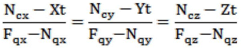
Specifically, two building key points M, N are selected, and a picture where the M points are located is selected based on one of the M points. Since it cannot be determined that the operator has clicked the M point and the N point in the same picture at the same time, the position of the N point needs to be automatically found out in the picture. Given that the coordinate of the self-defined coordinate system of N points is (N)cx,Ncy,Ncz) It is known that the shooting position of the picture where the M point is located is T ═ Xt, Yt, Zt, and the focal length is FpzThe angular difference between the X-axis between the imaging coordinate system X and the self-defined coordinate system is α, and the angular difference between the Z-axis between the imaging coordinate system Z and the self-defined coordinate system is β. Suppose that the position of N point in the picture is (N)ox,Noy) In the shooting coordinate system, the coordinate of N point is Pn ═ N (N)px,Npy0), focus Pf ═ 0, 0, Fpz). After rotation correction:
Qn=Pn×Rx×Rz=(Nqx,Nqy,Nqz)
Qf=Pf×Rx×Rz=(Fqx,Fqy,Fqz)
to this end, overdetermined sets of equations may be simultaneous:
note that only N is present in the equationox、NoyTwo unknowns, N needs to be judged after solvingox、NoyIf the value of (1) is not within the picture size range, the judgment is made that the N points are not displayed in the picture.
Step S16: intercepting an area between two building key points in the picture, detecting the cut area by using a canny operator, judging whether the two points need to be connected, and constructing the outer surface contour of the whole building by the connection to form a closed area.
Specifically, after M points and N points are found in the same picture, the two points and the area around the connecting line of the two points are cut off for edge detection. Calculating the projection of the cut region detection result on the connecting line of the two building key points by using a canny operator; and the part with the projection result of 0 accounts for the total length H% of the connecting line of the two building key points, and according to a set threshold value, if the H is judged to be higher than the threshold value, the two building key points are considered to be connected and are an edge of the building, otherwise, the two building key points are considered not to be connected.
If the picture of the M point and the picture of the N point can be judged that the MN is connected, the MN two points are connected with a solid line in a virtual three-dimensional space established by background processing equipment. If only one picture can judge that the MN is connected, a dotted line is connected in the virtual three-dimensional space. If no picture can judge that the MN is connected, the MN is not connected. The operator can select the connection function, when clicking the area between MN connection lines, the left button clicks to connect the solid line or change the broken line into the solid line, and the right button cancels the connection line.
Of all the building key points, the building key point at the edge is regarded as the edge key point of the building.
Judging whether the Z coordinate of the building edge key point is greater than a preset first threshold value, preferably, the first threshold value is 1 m, and if so, connecting the building edge key point with a point vertically projected on a horizontal plane; if the two building edge key points are connected, the projection points are also connected to form a closed area.
Step S17: and finding out the construction key points forming the closed area in a picture, and cutting off the corresponding area in the picture to carry out mapping so as to finish construction reconstruction.
Specifically, a simple mapping operation is performed after the construction of the outer surface profile of the entire building is completed. Firstly, all building key points forming the same closed area are selected, the positions of the corresponding key points are found in the related pictures, the corresponding areas are cut off, and one area may correspond to a plurality of pictures. And correcting the cut picture, and pasting the picture on a corresponding plane in a virtual three-dimensional space. The operator can select the mapping function, the mapping is changed when the left key clicks one mapping area, and the mapping is hidden when the right key clicks one mapping area.
The operator can point out one point of the upper plane and one point of the lower plane of any floor in one picture. And the background processing equipment automatically divides the building of the virtual three-dimensional space into multiple floors according to the coordinates of the two points, and marks the floors of all the special key points.
The invention provides a fire scene positioning system based on an unmanned aerial vehicle in embodiment 3. The system comprises the unmanned aerial vehicle, a camera and a gyroscope which are arranged on the unmanned aerial vehicle, and background processing equipment. Fig. 3 is a schematic structural diagram of functional modules in the background processing device.
A self-defined coordinate system establishing module 100 is arranged in the background processing equipment and is used for acquiring data of physical markers or special buildings placed in a plurality of places around a fire scene as markers;
the unmanned aerial vehicle positioning module 200 is used for manually pointing out two markers in a picture shot by the unmanned aerial vehicle and calculating the position of the unmanned aerial vehicle in a self-defined coordinate system by combining the click position and the attitude angle;
the key point positioning module 300 is used for manually pointing out the position of the same key point according to the two pictures shot by the unmanned aerial vehicle, calculating the position coordinates of the key point under the self-defined coordinate system by combining the click position, the attitude angle and the two shooting positions of the key point, and completing the positioning of the fire scene on the key point;
wherein, the unmanned aerial vehicle position is the shooting position promptly.
When a fire disaster occurs, disaster relief personnel evacuate the site, and the surrounding environment is simply surveyed. In the surveying process, a plurality of markers are placed to a more obvious place, and some special buildings are set as the markers. And flying the unmanned aerial vehicle, and shooting the fire scene by the surrounding camera. If need observe the specific position, then remove unmanned aerial vehicle to corresponding position after, shoot the marker downwards earlier, shoot the specific position afterwards. On the background processing equipment, the operator selects clear pictures of at least two markers. In the picture, the operator points out the marker, points out the construction key point and the special key point as much as possible, and numbers various points. After the points with the same number are pointed out in the two pictures, the coordinates of the points are directly displayed. And if the point of a certain number is not pointed out in the two pictures, prompting an operator.
Unmanned aerial vehicle orientation module 200 specifically includes:
the first correction module 201 is configured to establish a shooting coordinate system by using the shot picture center point as an origin, where the picture is horizontally in the positive x-axis direction to the left, vertically in the positive y-axis direction, and the direction pointing to the focus from the sensor area center point is in the positive z-axis direction;
converting a horizontal angle of an attitude angle of the unmanned aerial vehicle into an angle difference between an X axis of the self-defined coordinate system and an X axis of the shooting coordinate system between the shooting coordinate system and the self-defined coordinate system, and converting a pitch angle of the attitude angle of the unmanned aerial vehicle into an angle difference between a Z axis of the self-defined coordinate system and a Z axis of the shooting coordinate system; according to the right-hand spiral rule, taking the positive direction of the Z axis of the self-defined coordinate system as the direction of a thumb, and turning to the positive direction of the X axis of the shooting coordinate system from the positive direction of the X axis of the self-defined coordinate system as the positive direction of an angle; according to the right-hand spiral rule, taking the positive direction of the x axis of the shooting coordinate system as the direction of a thumb, turning the positive direction of the Z axis of the shooting coordinate system from the positive direction of the Z axis of the self-defined coordinate system as the positive direction of an angle;
the system is used for correcting the coordinates of two markers and the coordinates of a focus in a shooting coordinate system according to the condition that the origin of the shooting coordinate system is taken as the origin and the direction of XYZ axes of the self-defined coordinate system is taken as the direction;
and the shooting position calculation module 202 under the self-defined coordinate system is used for combining an overdetermined equation of the shooting position under the self-defined coordinate system according to the two direction vectors of the shooting position emitted to the corrected marker and the known coordinates of the two markers under the self-defined coordinate system so as to calculate the shooting position under the self-defined coordinate system.
The key point positioning module 300 specifically comprises
The second correction module 301 is configured to correct the key point coordinates and the focus coordinates in the two shooting coordinate systems corresponding to the two pictures respectively according to the shooting coordinate system origin as an origin and the self-determined coordinate system XYZ axis direction as a direction; each picture corresponds to a shooting coordinate system.
And a key point coordinate calculation module 302, configured to calculate coordinates of the key points in the self-defined coordinate system according to two direction vectors of the shooting position emitted to the corrected key points, and an overdetermined equation of the key points in the self-defined coordinate system in conjunction with the known shooting position coordinates in the self-defined coordinate system.
And the background processing equipment receives the picture sent by the unmanned aerial vehicle and the corresponding angle and GPS parameters during shooting. The self-defined coordinate system establishing module 100 obtains data of physical markers or special buildings placed at a plurality of places around a fire scene as markers for establishing a self-defined coordinate system. The camera should use a standard lens, and if a wide-angle lens is used, the image needs to be corrected. A coordinate system (hereinafter, collectively referred to as a shooting coordinate system) is established with a center point of a camera sensor area as an origin, and XYZ axis directions are set. The center point of the shot picture is used as the origin, the horizontal leftward direction of the picture is the positive direction of an x axis, the vertical upward direction of the picture is the positive direction of a y axis, and the direction pointing to the focus from the center point of the sensor area is the positive direction of a z axis. The shooting coordinate system takes the length of the pixel side of the shot picture as a unit (the width of a sensor size line divided by the width of a resolution line, which is generally square). If the camera can transmit the focal length during shooting, the focal length is directly converted into a numerical value taking the side length of the pixel as a unit; if the camera does not have the function, a small long marker is pasted on the edge of the outermost lens of the camera along the x-axis direction, the length of the marker is known, the distance from the center point of the outermost lens to the center point of the sensor area is known, the distance is not changed, and when the focal length is changed, the focal length can be calculated by calculating the length of the marker in a picture.
The horizontal attitude is kept when the unmanned aerial vehicle shoots, and the gyroscope records the horizontal angle and the pitch angle shot by the camera by taking the direction of the self-determined coordinate system as a standard. The background processing equipment converts the horizontal angle of the attitude angle recorded by the gyroscope into the angle difference between the X axis of the self-defined coordinate system and the X axis of the shooting coordinate system and converts the pitch angle of the attitude angle recorded by the gyroscope into the angle difference between the Z axis of the self-defined coordinate system and the Z axis of the shooting coordinate system between the shooting coordinate system and the self-defined coordinate system according to the definition of the shooting coordinate system; according to the right-hand spiral rule, taking the positive direction of the Z axis of the self-defined coordinate system as the direction of a thumb, and turning to the positive direction of the X axis of the shooting coordinate system from the positive direction of the X axis of the self-defined coordinate system as the positive direction of an angle; according to the right-hand spiral rule, the positive direction of the x axis of the shooting coordinate system is taken as the direction of the thumb, and the direction of the positive direction of the Z axis of the shooting coordinate system is turned from the positive direction of the Z axis of the self-defined coordinate system and is taken as the positive direction of the angle.
Under the above definition of the coordinate system, only the included angle between the two axes of the X axis and the Z axis is used, and if other definition methods are used, the included angle of the three axes needs to be calculated. When unmanned aerial vehicle shot, include two markers in the picture and can fix a position unmanned aerial vehicle. If a certain shooting position and angle can not shoot two markers, the operator can enable the unmanned aerial vehicle to keep shooting position conversion shooting angle, and the unmanned aerial vehicle can shoot the two markers and then observe the target.
For a picture containing two markers a and B, the drone positioning module 200 manually points out its position in the picture and provides the corresponding labels for the markers. The first correction module 201 can know that the position of the marker in the picture is (a)ox,Aoy) And (B)ox,Boy) And converting the coordinate value into a coordinate value Pa ═ A in a shooting coordinate systempx,Apy0) and Pb ═ Bpx,Bpy0) (level)The coordinates are obtained by taking the center of the image as an origin and performing simple addition and subtraction calculation according to the resolution, and the two points AB are both in the sensor area actually, and the vertical coordinates are both 0). At the same time, a focal length of F is obtainedpzIf the coordinate value of the focus in the shooting coordinate system is Pf (0, 0, F)pz). The first rectification module 201 obtains an angular difference α between the X-axis between the photographing coordinate system X and the self-determined coordinate system and an angular difference β between the Z-axis between the photographing coordinate system Z and the self-determined coordinate system through the recording of the gyroscope. Coordinate values of the point A, the point B and the focus in the shooting coordinate system are corrected according to the origin of the shooting coordinate system and the direction of XYZ axes of the self-defined coordinate system. The formula is as follows:
rotation of the matrix about the x-axis:
rotation of the matrix about the z-axis:
Qa=Pa×Rx×Rz=(Aqx,Aqy,Aqz)
Qb=Pb×Rx×Rz=(Bqx,Bqy,Bqz)
Qf=Pf×Rx×Rz=(Fqx,Fqy,Fqz)
where Qa, Qb, and Qf are coordinates of A, B, F points after correction. The imaging position calculation module 202 in the self-defined coordinate system can obtain a direction vector from the camera position T in the self-defined coordinate system to point a as (along the same principle as point B):
the camera looks in the direction of point A: (F)qx-Aqx,Fqy-Aqy,Fqz-Aqz)
The camera looks in the B point direction: (F)qx-Bqx,Fqy-Bqy,Fqz-Bqz)
The marker is self-definedThe position in the coordinate system is known as (A)cx,Acy,Acz) And (B)cx,Bcy,Bcz). And the position of the camera may be in simultaneous systems of equations:
this is an overdetermined equation, ideally with a unique solution. However, there is an error in actual use, and during solving, the values Xt and Yt can be solved simultaneously, and then the two Zt values are respectively solved and averaged to be the final Zt value. The values Xt, Yt, and Zt obtained by the shooting position calculation module 202 in the self-defined coordinate system are positions where the camera shoots in the self-defined coordinate system. If the two markers cannot be shot, the GPS parameters are used. Wherein, the unmanned aerial vehicle position is camera shooting position promptly.
The key point location module 300 is for the same key point, and the unmanned aerial vehicle camera takes pictures of it from two positions. The operator then points out the positions of the key points from the two pictures respectively. The second rectification module 301 thus knows that the positions of the key points in pictures C and D are (C)ox,Coy) And (D)ox,Doy) And converting the coordinate value into a coordinate value Pc ═ C in the shooting coordinate systempx,Cpy0) and Pd ═ Dpx,Dpy,0). At the same time, a focal length of F is obtainedpzIf the coordinate value of the focus in the shooting coordinate system is Pf (0, 0, F)pz). The second rectification module 301 obtains an angular difference α between the X-axis between the photographing coordinate system X and the self-determined coordinate system and an angular difference β between the Z-axis between the photographing coordinate system Z and the self-determined coordinate system through the recording of the gyroscope. Correcting the coordinate values of the key point and the focus in C, D diagram in the shooting coordinate system according to the direction of XYZ axis of the self-determined coordinate system with the origin of the shooting coordinate system as the origin, and correcting the corrected C, D point and the corrected focus F point in the self-determined coordinate systemCoordinates in the coordinate system:
Qc=Pc×Rx×Rz=(Cqx,Cqy,Cqz)
Qd=Pd×Rx×Rz=(Dqx,Dqy,Dqz)
Qf=Pf×Rx×Rz=(Fqx,Fqy,Fqz)
the key point coordinate calculation module 302 knows the positions of the unmanned aerial vehicle when shooting the C picture and the D picture as (C)cx,Ccy,Ccz) And (D)cx,Dcy,Dcz). Assuming that the coordinates of the key points are K ═ x (Xk, Yk, Zk), the system of equations can be simultaneous:
the equations are overdetermined equations, and Xk, Yk, and Zk are coordinates of the key points in the self-defined coordinate system after the key point coordinate calculation module 302 solves the equations. The key points are divided into two types, one type is a building key point, and the other type is a special key point. After all the key points are obtained, the background processing equipment establishes a virtual three-dimensional space and marks all the key points in the space.
The invention provides the fire scene positioning system based on the unmanned aerial vehicle of embodiment 4, which is based on embodiment 3, and is characterized in that after the key point positioning module 300 positions the key points of the building, the fire scene positioning system further comprises a building reconstruction module 400. Fig. 4 is a schematic structural diagram of functional modules in the background processing device.
The building reconstruction module 400 includes
The marking module 410 is used for marking all building key points of the outer contour of the top layer of the building;
the in-picture key point calculating module 420 is used for calculating the corresponding positions of the building key points in the picture according to the shooting positions of the picture, the coordinates of the building key points in the self-defined coordinate system and the shooting angles;
the closed region construction module 430 is used for intercepting a region between two building key points in the picture, detecting the cut region by using a canny operator, judging whether the two points need to be connected, and connecting the two points to construct the outer surface contour of the whole building to form a closed region;
and the mapping module 440 is configured to find out a building key point forming the closed area in a picture, and cut a corresponding area in the picture to perform mapping to complete building reconstruction.
The block 430 for constructing an enclosed area specifically includes:
a projection calculation module 431, configured to calculate, for the clipped area detection result, a projection on a connection line between the two building key points;
a module 432 for determining the connection between two building key points, which is configured to determine that the part with the projection result of zero accounts for H% of the total length of the connection between the two building key points, and determine, according to a set threshold, that if H is higher than the threshold, the two building key points are considered to be connected, and are an edge of a building, otherwise, the two building key points are considered not to be connected;
an edge key point selecting module 433, configured to consider, among all the building key points, the building key point located at the edge as an edge key point of the building;
an edge key point connecting module 444 for judging whether the Z coordinate of the building edge key point is higher, if so, connecting the building edge key point with a point vertically projected on a horizontal plane; if the two building edge key points are connected, the projection points are also connected to form a closed area.
In this embodiment, the labeling module 410 labels all building key points on the outer contour of the top floor of the building. The module 420 for calculating key points in the picture obtains the shooting position of the picture according to the above labels, and calculates the coordinates and shooting angles of the building key points in the self-defined coordinate systemThe corresponding positions of the building key points in the picture; specifically, two building key points M, N are manually selected, and a picture where the M points are located is selected based on one of the M points. Since it cannot be determined that the operator has clicked the M point and the N point in the same picture at the same time, the position of the N point needs to be automatically found out in the picture. Given that the coordinate of the self-defined coordinate system of N points is (N)cx,Ncy,Ncz) It is known that the shooting position of the picture where the M point is located is T ═ Xt, Yt, Zt, and the focal length is FpzThe angular difference between the X-axis between the imaging coordinate system X and the self-defined coordinate system is α, and the angular difference between the Z-axis between the imaging coordinate system Z and the self-defined coordinate system is β. Suppose that the position of N point in the picture is (N)ox,Noy) In the shooting coordinate system, the coordinate of N point is Pn ═ N (N)px,Npy0), focus Pf ═ 0, 0, Fpz). After rotation correction:
Qn=Pn×Rx×Rz=(Nqx,Nqy,Nqz)
Qf=Pf×Rx×Rz=(Fqx,Fqy,Fqz)
to this end, overdetermined sets of equations may be simultaneous:
note that only N is present in the equationox、NoyTwo unknowns, N needs to be judged after solvingox、NoyIf the value of (1) is not within the picture size range, the judgment is made that the N points are not displayed in the picture.
After the block construction module 430 finds the M point and the N point in the same picture, the projection calculation module 431 cuts the two points and the area around the connecting line of the two points, performs edge detection, and calculates the projection on the connecting line of the two building key points on the cut area detection result by using a canny operator; the module 432 for determining the connection between two building key points determines that the part of the projection result of 0 accounts for H% of the total length of the connection between the two building key points, if H is higher than a set threshold value, the two building key points are considered to be connected and are an edge of a building, otherwise, the two building key points are considered not to be connected.
If the picture of the M point and the picture of the N point can be judged that the MN is connected, the MN two points are connected with a solid line in a virtual three-dimensional space established by background processing equipment. If only one picture can judge that the MN is connected, a dotted line is connected in the virtual three-dimensional space. If no picture can judge that the MN is connected, the MN is not connected. The operator can select the connection function, when clicking the area between MN connection lines, the left button clicks to connect the solid line or change the broken line into the solid line, and the right button cancels the connection line.
The select edge keypoints module 433 considers the building keypoints at the edge to be the edge keypoints of the building among all the building keypoints.
Selecting an edge key point connecting module 444 to judge whether the Z coordinate of the building edge key point is greater than a preset first threshold value, wherein the first threshold value is preferably 1 m, and if so, connecting the building edge key point with a point vertically projected on a horizontal plane; if the two building edge key points are connected, the projection points are also connected to form a closed area.
The mapping module 440 finds out the construction key points forming the closed region in a picture, and cuts the corresponding region in the picture to perform mapping to complete the construction reconstruction. Specifically, a simple mapping operation is performed after the construction of the outer surface profile of the entire building is completed. Firstly, all building key points forming the same closed area are selected, the positions of the corresponding key points are found in the related pictures, the corresponding areas are cut off, and one area may correspond to a plurality of pictures. And correcting the cut picture, and pasting the picture on a corresponding plane in a virtual three-dimensional space. The operator can select the mapping function, the mapping is changed when the left key clicks one mapping area, and the mapping is hidden when the right key clicks one mapping area.
The operator can point out one point of the upper plane and one point of the lower plane of any floor in one picture. And the background processing equipment automatically divides the building of the virtual three-dimensional space into multiple floors according to the coordinates of the two points, and marks the floors of all the special key points.
It will be understood by those skilled in the art that all or part of the processes of the methods of the embodiments described above can be implemented by a computer program, which can be stored in a computer-readable storage medium, and when executed, can include the processes of the embodiments of the methods described above. The storage medium may be a magnetic disk, an optical disk, a Read-Only Memory (ROM), a Random Access Memory (RAM), or the like.