CN108763827B - Transmission tower finite element model establishing method and device - Google Patents
Transmission tower finite element model establishing method and device Download PDFInfo
- Publication number
- CN108763827B CN108763827B CN201810645612.4A CN201810645612A CN108763827B CN 108763827 B CN108763827 B CN 108763827B CN 201810645612 A CN201810645612 A CN 201810645612A CN 108763827 B CN108763827 B CN 108763827B
- Authority
- CN
- China
- Prior art keywords
- cross
- transmission tower
- point
- array
- section
- Prior art date
- Legal status (The legal status is an assumption and is not a legal conclusion. Google has not performed a legal analysis and makes no representation as to the accuracy of the status listed.)
- Active
Links
Images


Classifications
-
- G—PHYSICS
- G06—COMPUTING OR CALCULATING; COUNTING
- G06F—ELECTRIC DIGITAL DATA PROCESSING
- G06F30/00—Computer-aided design [CAD]
- G06F30/20—Design optimisation, verification or simulation
- G06F30/23—Design optimisation, verification or simulation using finite element methods [FEM] or finite difference methods [FDM]
Landscapes
- Engineering & Computer Science (AREA)
- Physics & Mathematics (AREA)
- Theoretical Computer Science (AREA)
- Computer Hardware Design (AREA)
- Evolutionary Computation (AREA)
- Geometry (AREA)
- General Engineering & Computer Science (AREA)
- General Physics & Mathematics (AREA)
- Management, Administration, Business Operations System, And Electronic Commerce (AREA)
Abstract
The power transmission tower is segmented, the local serial number of the connecting point and the serial number of the cross section of the component which are associated with each component in the segment are determined in a segmented mode one by one, the local serial number of the reference point is determined according to the specified principle of the cross section direction of the connecting point and the angle steel component, so that the component and connecting point associated array is generated, the modeling file of the finite element model of the power transmission tower is generated, and the finite element model of the power transmission tower is established.
Description
Technical Field
The invention relates to the technical field of power transmission tower model establishment, in particular to a power transmission tower finite element model establishment method and device.
Background
With the rapid development of economy in China, the demand on electric power energy is continuously increased, the region of China is vast, the construction of a power grid is rapidly developed, and the power transmission tower obtained by design is influenced by aspects such as landform, climate characteristics, human environment and the like, and is various in types and forms.
In order to better evaluate the safety of the transmission tower and the tower-line system under the environmental load, an analytical model of the transmission tower needs to be established, and a finite element model is most commonly used. Due to the fact that the types of the power transmission towers are various, particularly the cross section directions of the angle steel components of the power transmission towers are complex in spatial distribution, if the angle steel components cannot be placed correctly in the finite element model, the obtained model cannot well reflect the dynamic characteristics of the original structure, and even an error model is obtained. Therefore, the finite element model of the power transmission tower is quickly and accurately established, which is an important premise for accurately calculating the dynamic response of the power transmission tower and the tower and line system and is a fundamental guarantee for formulating the vibration control scheme of the power transmission tower and the tower and line system.
Disclosure of Invention
The invention provides a power transmission tower finite element model establishing method and device, which can quickly and correctly determine the cross section direction of an angle steel member, ensure that a model is closer to a prototype and solve the technical problem that the traditional modeling technology cannot quickly and correctly determine the cross section direction of the angle steel member.
The invention provides a power transmission tower finite element model establishing method, which comprises the following steps:
s1, establishing a global coordinate system, and segmenting the power transmission tower according to a given design drawing;
s2, calculating the coordinates of the connection points in each section according to the characteristic structure of the segmented power transmission tower, determining the local number of the connection points and the overall number of the corresponding connection points which are associated with each member in the section, and determining the cross section number of each member;
s3, determining the reference point coordinates, the reference point local numbers and the corresponding reference point general numbers of the cross section directions of each member according to the local numbers of the connection points associated with each member and the designated principle of the cross section directions of the angle steel members;
s4, generating a member and connecting point association array according to the connecting point local number, the reference point local number and the member cross section number of each member;
s5, determining the connection point total number and the reference point total number corresponding to the connection point association array;
s6, generating a modeling file of the finite element model of the power transmission tower according to the connection point total number, the reference point total number and the component cross section number corresponding to the component and the connection point association array, the connection point coordinates, the reference point coordinates, the given material parameter array and the component cross section array;
and S7, importing the modeling file into finite element software to establish a finite element model of the power transmission tower.
Preferably, the segmenting the transmission tower in the step S1 specifically includes:
the power transmission tower is divided into a main structure and auxiliary cross arms, each pair of auxiliary cross arms is used as a subsection, and each characteristic structure is used as a subsection for the main structure along the height direction of the power transmission tower.
Preferably, the feature is comprised of more than one sub-structure forming an annular array;
the substructure comprises a substructure 1, a substructure 2 and the substructure 3, the connection points of the substructure 1 are located at least at two different heights, the connection point types comprise P2, P3, P4 and P5, the connection points of the substructure 2 are located at the same height, the connection point types comprise P1 and P2, the connection points of the substructure 3 are located at least at two different heights, the connection point types comprise P2, P3, P4 and P5;
the connection point types are specifically: the connecting point of the components on the center line of the height direction of the power transmission tower is defined as a P1 connecting point; the connecting points on the four ridge lines of the power transmission tower outline are defined as P2 connecting points; defining a connecting point on a horizontal plane coordinate axis after projection in the power transmission tower contour surface as a P3 connecting point; defining a connecting point which is positioned in a horizontal plane coordinate system quadrant after projection in the contour plane of the power transmission tower as a P4 connecting point; the connection point in the transmission tower that is not on the ridgeline, the profile and the center line in the direction of the tower height is defined as the P5 connection point.
Preferably, the step S2 specifically includes:
acquiring a connection point corresponding to one substructure of the characteristic structure from a design drawing, calculating coordinates and local numbers of the connection points, and acquiring the coordinates and local numbers of the connection points of the remaining substructures forming the annular array through annular array operation;
the component cross-section number for each component is determined from component model specification information associated with each component within the sub-structure.
Preferably, the step S3 specifically includes:
according to a design drawing and a method for specifying the cross section direction of the angle steel member, determining the reference point coordinates, the reference point local numbers and the reference point total numbers of the member cross section direction.
Preferably, the accessory cross arm is composed of two substructures;
the step S2 further includes:
acquiring a connection point corresponding to one substructure of the auxiliary cross arm from a design drawing, calculating coordinates and local numbers of the connection points, judging whether the other substructure of the auxiliary cross arm is symmetrical to the substructure, if so, obtaining the coordinates and the local numbers of the connection points of the substructure forming the annular array through annular array operation, and if not, independently generating the coordinates and the local numbers of the connection points of the other substructure;
the member cross-section number of each member is determined from member model specification information associated with each member within the substructure of the secondary cross-arm.
Preferably, the step S4 specifically includes:
and taking two connecting point local numbers, one reference point local number and one member cross section number of each member as the first four dimensions of the member and connecting point associated array, and calculating a cross section number rotation array according to the member cross section numbers corresponding to the feature structures with different heights to be used as the fifth dimension of the member and connecting point associated array.
Preferably, the step S5 specifically includes:
and determining a connection point overall number and a reference point overall number corresponding to the connection point association array according to the connection point local number and the reference point local number of the connection point association array of the component.
Preferably, the step S6 specifically includes:
creating a modeling file, and generating the following commands in the modeling file:
preprocessing a file header;
setting a beam unit type;
generating a set material attribute and a cross section parameter according to the component cross section array;
connecting the two connecting points into a line in sequence according to the connecting point total numbers corresponding to the first two dimensions in the member and connecting point association array;
selecting the line;
assigning a material type, a unit type, a reference point overall number and a member cross-section number to the member according to the last two dimensions in the member and connection point associated array;
generating and dividing grids;
and finishing the pretreatment.
The invention also provides a power transmission tower finite element model establishing device, which comprises a processor and a memory, wherein the processor comprises:
the memory is used for storing program codes and transmitting the program codes to the processor;
the processor is configured to execute the aforementioned transmission tower finite element model building method according to instructions in the program code.
According to the technical scheme, the invention has the following advantages:
the invention provides a method and a device for establishing a finite element model of a power transmission tower, wherein the method comprises the following steps: establishing an integral coordinate system, and segmenting the power transmission tower according to a given design drawing; calculating the coordinates of the connection points in each section according to the characteristic structure of the segmented power transmission tower, determining the local number of the connection points and the overall number of the corresponding connection points which are associated with each member in the section, and determining the cross section number of each member; determining the reference point coordinate of the section direction of each member, the reference point local number and the corresponding reference point total number according to the connection point local number associated with each member and the angle steel member section direction designation principle; generating a member and connecting point association array according to the connecting point local number, the reference point local number and the member cross section number of each member; determining a connection point total number and a reference point total number corresponding to the component and the connection point association array; generating a modeling file of the finite element model of the power transmission tower according to the connection point total number, the reference point total number and the component cross section number, the connection point coordinates, the reference point coordinates, the given material parameter array and the component cross section array corresponding to the component and the connection point association array; and importing the modeling file into finite element software to establish a finite element model of the power transmission tower. The power transmission tower is segmented, the local serial number of the connecting point and the serial number of the cross section of the component which are associated with each component in the segment are determined in a segmented mode one by one, the local serial number of the reference point is determined according to the specified principle of the cross section direction of the connecting point and the angle steel component, so that the component and connecting point associated array is generated, the modeling file of the finite element model of the power transmission tower is generated, and the finite element model of the power transmission tower is established.
Drawings
In order to illustrate the embodiments of the invention more clearly, the drawings that are needed for describing the embodiments or the prior art will be briefly described below, it being obvious that the drawings in the following description are only some embodiments of the invention, and that other drawings may be obtained by those skilled in the art without inventive exercise.
Fig. 1 is a schematic diagram of a transmission tower finite element model building method according to an embodiment of the present invention;
fig. 2 is a schematic diagram of three sub-structures of a transmission tower in a transmission tower finite element model building method provided by the invention;
FIG. 3 is a schematic diagram of connection points and component numbers during operation of an annular array in a finite element model building method of a transmission tower according to the present invention;
FIG. 4 is a schematic diagram of a local coordinate system of a cross section of an angle beam and two end points and reference points thereof;
fig. 5 is a schematic view of a power transmission tower from top to bottom in a finite element model building method for a power transmission tower according to the present invention;
fig. 6 is a schematic diagram of a part number and components of a tower leg structure connection point in the transmission tower finite element model building method provided by the invention.
Detailed Description
The invention provides a power transmission tower finite element model establishing method and device, which can quickly and correctly determine the cross section direction of an angle steel member, ensure that a model is closer to a prototype and solve the technical problem that the traditional modeling technology cannot quickly and correctly determine the cross section direction of the angle steel member.
In order to make the objects, features and advantages of the present invention more obvious and understandable, the technical solutions in the embodiments of the present invention will be clearly and completely described below with reference to the accompanying drawings in the embodiments of the present invention, and it is obvious that the embodiments described below are only a part of the embodiments of the present invention, and not all of the embodiments. All other embodiments, which can be derived by a person skilled in the art from the embodiments given herein without making any creative effort, shall fall within the protection scope of the present invention.
Referring to fig. 1, an embodiment of a method for establishing a finite element model of a transmission tower according to the present invention includes:
101. establishing an integral coordinate system, and segmenting the power transmission tower according to a given design drawing;
segmenting the transmission tower, wherein the segmentation is according to structural features, so that the segmentation is called a feature structure; the feature usually has symmetry, e.g. the body part naturally divides the feature into four parts by coordinate axes, called substructures, which operate through a circular array, resulting in a feature. A circular array operation is used that, in addition to the rotation of the coordinates of the connection points, also involves the calculation of corresponding cross-sectional information.
102. Calculating the coordinates of the connection points in each section according to the characteristic structure of the segmented power transmission tower, determining the local number of the connection points and the overall number of the corresponding connection points which are associated with each member in the section, and determining the cross section number of each member;
the local number of the connection point is used for calculating a reference point and generating a component and connection point association array, the connection point coordinate is used for calculating a reference point coordinate, the overall number of the connection point is used for generating a modeling file, and the overall number of all the connection points in one modeling file is different and unique. While the local numbering of the connection points may occur repeatedly within different segments.
103. Determining the reference point coordinate of the section direction of each member, the reference point local number and the corresponding reference point total number according to the connection point local number associated with each member and the angle steel member section direction designation principle;
as shown in fig. 4, the description of the angle beam requires two end points (i.e. two connection points) (i, j) and a reference point (k) in the xy-plane of the local coordinate system, according to the specifications of the finite element software ANSYS in relation to the beam-shaped element. According to the rule of the right hand, the thumb points to the point j from the point i, the forefinger points to the point k and follows the side direction of the angle steel A, and the middle finger points to the direction opposite to the side direction of the angle steel B. The angle steel A side selection principle is that a point k is a connection point, but the point k is not collinear with the points i and j, if no connection point can be used as a reference point of a member, corresponding reference point coordinates are generated according to a right-hand rule, and overall numbers are given. This step may be performed by a coordinate operation. After the coordinates of the reference point are calculated (if the connection point is found to be the reference point, coordinate calculation is not needed, the connection point is directly used as the reference point, and if the connection point is not used as the reference point, the coordinates of the reference point are calculated), the reference point can be numbered, and the local number of the reference point and the total number of the corresponding reference point can be obtained. As can be seen from this description and the actual situation of the transmission tower structure, the connection point can be usually found as a reference point, and coordinate calculation is not needed, unless there is no connection point as a reference point, a new point needs to be calculated as a reference point, and a new overall number is assigned. That is, if the reference points are connection points, they share local and global numbers.
104. Generating a member and connecting point association array according to the connecting point local number, the reference point local number and the member cross section number of each member;
105. determining a connection point total number and a reference point total number corresponding to the component and the connection point association array;
106. generating a modeling file of the finite element model of the power transmission tower according to the connection point total number, the reference point total number and the component cross section number, the connection point coordinates, the reference point coordinates, the given material parameter array and the component cross section array corresponding to the component and the connection point association array;
107. and importing the modeling file into finite element software to establish a finite element model of the power transmission tower.
Further, the segmenting the transmission tower in step 101 specifically includes:
the power transmission tower is divided into a main structure and auxiliary cross arms, each pair of auxiliary cross arms is used as a subsection, and each characteristic structure is used as a subsection for the main structure along the height direction of the power transmission tower.
Referring to FIG. 2, further, the feature is composed of more than one sub-structure forming a circular array;
the substructure comprises substructure 1, substructure 2 and substructure 3 ((a), (b), (c) in fig. 2), the connection points of substructure 1 are located at least at two different heights, the connection point types comprise P2, P3, P4 and P5, the connection points of substructure 2 are located at the same height, the connection point types comprise P1 and P2, the connection points of substructure 3 are located at least at two different heights, the connection point types comprise P2, P3, P4 and P5;
the connection point types are specifically: the connecting point of the components on the center line of the height direction of the power transmission tower is defined as a P1 connecting point; the connecting points on the four ridge lines of the power transmission tower outline are defined as P2 connecting points; defining a connecting point on a horizontal plane coordinate axis after projection in the power transmission tower contour surface as a P3 connecting point; defining a connecting point which is positioned in a horizontal plane coordinate system quadrant after projection in the contour plane of the power transmission tower as a P4 connecting point; the connection point in the transmission tower that is not on the ridgeline, the profile and the center line in the direction of the tower height is defined as the P5 connection point.
Further, step 102 specifically includes:
acquiring a connection point corresponding to one substructure of the characteristic structure from a design drawing, calculating coordinates and local numbers of the connection points, and acquiring the coordinates and local numbers of the connection points of the remaining substructures forming the annular array through annular array operation;
the component cross-section number for each component is determined from component model specification information associated with each component within the sub-structure.
It should be noted that the circular array operation is shown in fig. 3, the left diagram a is the local number of the connection point, the right diagram b is the member number for calculation naming, according to the design drawing, the combination of the member 1 and the member 5 is one of the substructures, the rest of the substructures are the same as the substructures in topology, i.e., the members 1,2, 3, 4 correspond to the members 5, 6, 7, 8, the connection point with the local number of 1 corresponds to the connection point with the local number of 2, 3, 4, and the connection point with the local number of 5 corresponds to the connection point with the local number of 6, 7, 8. Thus, referring to FIG. 3, this step is specifically to obtain the connection point (usually the number and coordinates of the point on the first quadrant and the X-axis, the number of the line and the local number of the connection point with it) corresponding to a sub-structure of the feature from the design drawing, i.e. the connection points 1,5, 6 of the combined substructure of member 1 and member 5 are taken, then the three connection points are numbered 1,5, 6 and the coordinates of the connection points 1,5, 6 are calculated, then, because the topology of the rest substructures is the same, the coordinates of the connecting points 2, 6 and 7 can be obtained by performing rotation transformation according to the coordinates of the connecting points 1,5 and 6, and these three connection points are the resulting connection points of the substructure, rotated once, so the name local number is incremented by one, the coordinates of the connection points and the local numbering of the connection points of the remaining sub-structures forming the circular array can be obtained according to the principle of operation of this circular array. And then, acquiring the component model specification information associated with each component according to a design drawing, numbering the components in sequence according to the condition whether the component model specification information is the same, numbering the same component cross sections if the component model specification information is the same, and numbering another component cross section if the component model specification information is different. Meanwhile, an index of the characteristic structure, the member cross section number and the member model specification information is established.
It should be noted that, because of the symmetry of the transmission tower, the substructures of the feature generally have symmetry, and a plurality of substructures may form a circular array around the center.
Note that, 1. circular array operation: for example, for a structure with four feature substructures, the number and coordinates of points on the first quadrant and the x-axis, the number of lines and the local number of the connection points with the lines are determined, and then the numbers are obtained by rotation transformation, and meanwhile, the corresponding member cross section numbers are required to be established.
2. The coordinates of the points are marked on the standard design drawing, or can be conveniently calculated according to the drawing; the local number is defined by self, and the number value is increased according to the number interval of the required rotation; the numbering within the feature substructures is not specifically limited, except that general numbering is used, as the principle is to facilitate establishing a connection between the links and the numbering.
3. The standard design drawing contains the connection relation of the components and the information of the model and specification of the components (namely the used steel material and the cross section size); such designs usually take into account certain symmetries, such as B, C and D from A rotation, which are designed using the same materials and cross-sectional dimensions (note: inconsistencies are not excluded, but it is certain that most designs are designed symmetrically). Since the number of substructures in each feature has been taken into account in the feature substructures, e.g. the number of substructures is 4, the interval 3 is numbered in the substructures, so that when the rotation is changed, only 1 is needed to be added to the current number, e.g. 5, and the numbers 6, 7, 8 are obtained in turn after the rotation.
4. Here, the topological identical feature structures satisfy the similarity that x and y coordinates can be made identical through proper scaling transformation, so that the B structure coordinate can be obtained through the a structure coordinate as long as the proportional relation of one corresponding connecting line and the translation distance in the z direction are known. In addition to the difference in point coordinates between a and B, there may be differences in component model specification information, which is determined by a rotation array of cross-sectional numbers, which can be referred to in the design drawings.
5. The finite element modeling of the transmission tower structure essentially determines the connection line relationship between the coordinates of points and the numbers of the points, and endows the connection lines with material properties and cross section characteristics. One advantage of the present application is that these operations are simplified by structural symmetry and similarity, among other things. In this respect, a circular array is a representation of symmetry, and topological identity refers to structural similarity.
Further, step 103 specifically includes:
according to a design drawing and a method for specifying the cross section direction of the angle steel member, determining the reference point coordinates, the reference point local numbers and the reference point total numbers of the member cross section direction.
According to the specifications of the finite element software ANSYS for beam-shaped elements, two end points (i, j) and a reference point (k) are required for describing the angle beam, the reference point k being in the xy-plane of the local coordinate system. According to the rule of the right hand, the thumb points to the point j from the point i, the index finger points to the point k and follows the side direction of the angle steel A, and the middle finger points to the direction opposite to the side direction of the angle steel B, so that the cross section direction of the angle steel component can be obtained. And then, determining the reference point coordinates and the overall number of the section direction of the angle steel member according to a design drawing and a designated method of the cross section direction of the angle steel member. For most components, the existing connection points can be used as reference points; if no connection point can be used as a reference point for the component, corresponding reference point coordinates are generated and numbered.
Further, the accessory cross arm is composed of two substructures; in particular two substructures 3.
Step 102 further comprises:
acquiring a connection point corresponding to one substructure of the auxiliary cross arm from a design drawing, calculating coordinates and local numbers of the connection points, judging whether the other substructure of the auxiliary cross arm is symmetrical to the substructure, if so, obtaining the coordinates and the local numbers of the connection points of the substructure forming the annular array through annular array operation, and if not, independently generating the coordinates and the local numbers of the connection points of the other substructure;
the member cross-section number of each member is determined from member model specification information associated with each member within the substructure of the secondary cross-arm.
The secondary cross arm generally consists of two substructures, which may or may not have the same topology, and need to be determined first. The member cross section number determination of the auxiliary cross arm member is the same as the member cross section number determination method of the feature structure, and is not described in detail herein.
Further, step 104 specifically includes:
taking two connection point local numbers, a reference point local number and a member cross section number of each member as the first four dimensions of the member and connection point associated array, and calculating a cross section number rotation array according to the member cross section numbers corresponding to the feature structures with different heights to be used as the fifth dimension of the member and connection point associated array;
wherein the local numbering of the connection points and the local numbering of the reference points in the substructures of the topologically identical features are the same, and the cross-sectional numbering of the identically numbered members in the substructures of the topologically identical features may be different.
It should be noted that, for feature structures with the same topology, it is only necessary to obtain the connection point coordinates and local numbers, the reference point coordinates and numbers, and the member cross section numbers of the sub-structures of one feature structure, and obtain the first four dimensions of the member and connection point association array of the entire feature structure according to the operation of the ring array, while other feature structures only need to record the member cross section numbers to the cross section number rotation array, and then place the cross section number rotation array containing all the member cross section numbers in the fifth dimension of the member and connection point association array, so that all the segmented members with the same topology as the feature structure can be described, as shown in table 1, the member cross section numbers are given by the segment number indexes, and the program codes can be simplified.
It should be noted that, after the above steps are performed according to the design drawing to obtain the several associated arrays of the components and the connection points shown in table 1, the structure of the transmission tower can be expressed. For example, each member in table 1 represents all members of one substructure of a feature, and the connection point coordinates and local number, reference point coordinates and number, and member cross-section number of the entire feature can be obtained by performing a looping operation on the information of the substructure, while other features having the same topology as the feature, because the topological structure is the same, and the cross section steel number and the specification of the component are different between the corresponding components, i.e. the information of the model and the specification of the component is different, so the information can be expressed by different numbers of the cross sections of the component, all segmented components that are topologically identical to the feature can therefore be described by a rotation array of cross-sectional numbers comprising all component cross-sectional numbers, the component and connection point association array shown in table 1 can therefore describe all modeling information for topologically identical features. The modeling information of the entire transmission tower can be formed by associating the array of several components with the connection points. Therefore, the program can be simplified, and the modeling speed and the modeling efficiency can be improved.
Further, step 105 specifically includes:
and determining a connection point overall number and a reference point overall number corresponding to the connection point association array according to the connection point local number and the reference point local number of the connection point association array of the component.
Since the local numbers are repeated in the segments and the local numbers mainly serve to simplify the program codes, so that a member and connection point association array can describe the members of all the substructures in the segments, when the modeling file is established, in order to clearly determine each connection point and the reference point, the overall number corresponding to the local number needs to be determined according to the segment number index.
Further, step 106 specifically includes:
creating a modeling file, and generating the following commands in the modeling file:
preprocessing a file header;
setting a beam unit type;
generating a set material attribute and a cross section parameter according to the component cross section array;
connecting the two connecting points into a line in sequence according to the connecting point total numbers corresponding to the first two dimensions in the member and connecting point association array; specifically, it may be a command to find the corresponding coordinates of the connection point from the connection point population number and then generate the line from the coordinates.
Selecting the line;
assigning a material type, a unit type, a reference point overall number and a member cross-section number to the member according to the last two dimensions in the member and connection point associated array;
generating and dividing grids;
and finishing the pretreatment.
The above is a detailed description of an embodiment of the finite element model building method of the transmission tower according to the present invention, and the following is a detailed description of another embodiment of the finite element model building method of the transmission tower according to the present invention.
Another embodiment of the method for establishing a finite element model of a power transmission tower provided by the invention comprises the following steps:
1) segmenting the power transmission tower according to a given design drawing to generate a material parameter array and a member cross section array;
2) calculating coordinates of connecting points in each segment according to the segments obtained in the step 1), and determining local numbers and overall numbers of the connecting points;
3) acquiring a connection point number and a member cross section number associated with each member in the section according to the local connection point number in the section obtained in the step 2) and a given design drawing;
4) determining the reference point coordinates and the overall number of the cross section direction of each member according to the connection point number associated with the member and the angle steel member cross section direction designation principle obtained in the step 3);
5) combining and generating a key point coordinate array according to the connection point coordinates and the reference point coordinates obtained in the steps 1) and 4);
6) generating a component and connection point association array according to the connection point local number, the reference point local number and the cross section number obtained in the steps 3) and 4), and determining a corresponding connection point overall number, a reference point overall number and a corresponding cross section number;
7) automatically generating a modeling file of a finite element model of the power transmission tower by adopting a program according to the member cross section number, the connection point array and the member and connection point association array obtained in the steps 3), 5) and 6);
8) and 7) importing finite element software to establish a finite element model of the power transmission tower according to the modeling file obtained in the step 7).
The classification principle of the power transmission tower nodes is as follows: the connecting point of the components on the center line of the height direction of the power transmission tower is defined as a P1 connecting point; the connecting points on the four ridge lines of the power transmission tower outline are defined as P2 connecting points; defining a connecting point on a horizontal plane coordinate axis after projection in the power transmission tower contour surface as a P3 connecting point; defining a connecting point which is positioned in a horizontal plane coordinate system quadrant after projection in the contour plane of the power transmission tower as a P4 connecting point; the connection point in the transmission tower that is not on the ridgeline, the profile and the center line in the direction of the tower height is defined as the P5 connection point.
The basic principle of the power transmission tower segmentation is as follows: firstly, dividing a power transmission tower into a main body structure and auxiliary cross arms, wherein each pair of cross arms is used as a subsection; then, for the main structure, each feature acts as a segment along the height of the transmission tower.
The feature is composed of 4 substructures forming a circular array, wherein the substructures are of the type having a substructure 1 and a substructure 2. Substructure 1 is characterized by: the connection points are located at least at two different heights, the connection point types including P2, P3, P4 and P5. Substructure 2 is characterized by: the connection points are located at the same height, and the connection point types include P1 and P2.
The auxiliary cross arm is as follows: each secondary cross-arm consists of 2 substructures, of which the substructure type is substructure 3. Substructure 3 is characterized by: the connection points are located at least at two different heights, the connection point types include P2, P3, P4 and P5, where P2 is the connection point of the secondary cross arm to the spine of the body structure.
The main structure comprises one or more than one characteristic structures, and each characteristic structure has one or more than one characteristic structures with the same topology; each secondary cross arm is composed of 2 symmetrical or different substructures 3.
The process of generating the component cross section array comprises: forming a material parameter array according to a design drawing and steel numbers, wherein the material parameter array comprises elastic modulus, Poisson ratio, density, yield strength and ultimate strength; and numbering is carried out in an increasing order according to the sequence of steel number first and specification size later to form an array for storing the specification model information of the cross section.
The process of calculating coordinates of connection points in the segments and determining the number of the connection points comprises the following steps: calculating the connection point coordinates and local numbers of the substructures in the segments according to a design drawing, and obtaining the connection point coordinates and local numbers of the other 3 substructures through annular array operation; calculating a connection point coordinate system and a local number of a substructure in the auxiliary cross arm segment according to a design drawing, and if 2 substructures of the cross arm are the same, obtaining a connection point coordinate and a local number of another substructure through annular array operation; otherwise, the coordinates of the connection point and the local number of the other substructure are generated separately.
The process of obtaining the connection point number and the cross-section number associated with the member within the segment includes: and directly consulting and obtaining the connection point number and the component model specification information associated with each component in the substructure according to a design drawing, and obtaining the connection point number and the component model specification information associated with each component in the rest substructures through annular array operation. The model specification information may be directly mapped to the cross-section number.
The method for determining the cross section direction of the angle steel member comprises the following steps: according to the specifications of the finite element software ANSYS for beam-shaped elements, two end points (i, j) and a reference point (k) are required for describing the angle beam, the reference point k being in the xy-plane of the local coordinate system. According to the rule of the right hand, the thumb points to the point j from the point i, the forefinger points to the point k and follows the side direction of the angle steel A, and the middle finger points to the direction opposite to the side direction of the angle steel B.
The process of determining the reference point coordinates and the overall number of the cross-section direction of each member includes: and determining the reference point coordinates and the overall number of the section direction of the angle steel member according to a design drawing and a designated method of the cross section direction of the angle steel member. For most components, the existing connection points can be used as reference points; if no connection point can be used as a reference point for the component, corresponding reference point coordinates are generated and numbered.
Generating an array of associations of members and connection points comprises: the first two dimensions of the array are the connection points of the starting and terminating ends of the member, respectively, the third dimension is the reference point of the member, and the fourth dimension is the cross-sectional number of the member.
The process of automatically generating the modeling file of the finite element model of the power transmission tower by adopting a program comprises the following steps: generating by a program according to the APDL file format requirement of ANSYS software, and writing out a pre-processing file header; writing a command for setting the type of the beam unit; writing a command for setting material properties and cross section parameters according to the member cross section array; writing out the connection points and the reference points as key points; writing a command for sequentially connecting the key points represented by the first two dimensions in the associated array into a line; writing a command to select the line; writing a command which is given to the line material type, the unit type, the reference point and the cross section number according to the last two dimensions in the associated array; writing out commands for grid division and generation; and writing a preprocessing ending command.
Compared with the similar prior art, the technical scheme provided by the invention has the following advantages:
1. the data of the technical scheme of the invention is derived from design drawings, the modeling method is simple and easy to implement and has strong operability, and the obtained model is accurate and reliable;
2. the technical scheme of the invention decomposes the power transmission tower from top to bottom, extracts the characteristic substructure for modeling, can be widely applied to finite element modeling of various types of power transmission towers, and the substructure analysis method and program with the same topological characteristic structure can be directly transplanted;
3. according to the technical scheme, the input file for ANSYS software APDL modeling is automatically generated through programming, and the finite element model of the power transmission tower can be generated by importing the file from an ANSYS classic interface without other operations.
Referring to fig. 5 and fig. 6, an application example provided by the present invention will be described as follows:
taking a certain drum type double-loop power transmission tower as an example, adopting an MATLAB programming program, gradually establishing a finite element model of the power transmission tower through a top-down decomposition method shown in FIG. 5, and writing an APDL file of the model, wherein the method specifically comprises the following steps:
and step 1) forming a material parameter array and a component cross section array according to the coordinates of the connecting points and the reference points calculated by the design drawing.
And 2) determining the local number of the substructure connection point of the feature structure to form a member association array.
And 3) generating an APDL file required by ANSYS software modeling.
And 4) importing the APDL file obtained in the step 3) from ANSYS software, and directly generating a finite element model of the power transmission tower.
The connecting point coordinate information calculated in the step 1) forms a member cross section array, and specifically comprises the following steps:
a) integral coordinate system
The z-axis of the overall coordinate system is along the direction of the tower height, the x is vertical to the direction of the lead, and the y-axis is along the direction of the lead.
b) Calculating connection point and reference point coordinates
According to a design drawing, considering the similarity of characteristic structures, programming to quickly generate coordinates of the connection points and the reference point groups, storing the coordinates in the array NC of 3xNN, wherein NN is the total number of the connection points and the reference points, and storing the coordinates (x, y, z) of the connection points or the reference points in the overall coordinate system in each row. Each segment counts the substructural ridge connection points and the quadrant intra-connection points, the counted connection points are not counted, and the result is stored IN the array IN of 1xND, ND is the number of segments. The connection points are numbered in increasing order in segments, then the connection points on the z-axis are numbered, and finally the reference points are numbered, the latter two cases usually involving a small number of points.
c) Forming an array of material parameters
According to a design drawing, counting the types of the steel grades NG, numbering the steel grades in sequence, storing the steel grades in an array MG of 5xNG, and storing the elastic modulus, the Poisson ratio, the density, the yield strength and the ultimate strength in each row.
d) Forming arrays of component cross-sections
According to a design drawing, the number NS of the cross sections used by the whole power transmission tower is counted and numbered in sequence according to the steel number and the specification, the number NS of the cross sections is stored in a cellular array SPEC of 6xNS, and the specification, the steel number and the specific size of the cross section are stored in each row, for example:
L80X8,1,0.080,0.080,0.008,0.008
step 2) determining the local number of the substructure connection point of the feature structure to form a component association array, which specifically comprises the following steps:
a) the local numbering of the substructure connection points of the feature is determined according to fig. 3, which is shown in fig. 6, taking the tower legs as an example.
b) According to the design drawing, the member cross-sectional direction designation method, and fig. 6, it is determined that the members are associated with the connection points in an array EN of 4xNE, NE is the total number of the members, and each column stores the start point, end point, reference point, and cross-sectional number of the member. Due to the large number of components in the substructure of fig. 6, only typical components are listed, as shown in table 1:
TABLE 1 substructure member and connection point association array and cross-section number rotation array
| Component association array | Starting point | Terminal point | Reference point | Cross section numbering | Array of alternating numbers of cross sections |
| Member (1,5) | 1 | 5 | 8 | 14 | [14,13,12,11] |
| Member (1,17) | 1 | 17 | 8 | 25 | [25,25,25,25] |
| Component (17,5) | 17 | 5 | 1 | 16 | [16,16,16-16] |
| Component (21,9) | 21 | 9 | 1 | 17 | [17,17,17,17] |
| Component (21,13) | 21 | 13 | 1 | 18 | [18,18,18,18] |
| Component (34,13) | 34 | 13 | 1 | 29 | [29,27,27,25] |
| Component (17,25) | 17 | 25 | 5 | 16 | [16,16,16,16] |
| Component (21,29) | 21 | 29 | 9 | 18 | [24,22,20,18] |
| Component (33,34) | 33 | 34 | 15 | 29 | [29,28,28,24] |
| Member (33,533) | 33 | 533 | 36 | 22 | [22,21,20,19] |
c) The topological same as that of fig. 6 has four feature structures, which have corresponding local connection point numbers, and all the local connection point numbers and coordinates can be obtained through a circular array operation or a rotation operation, but the cross section steel numbers and specifications of the components are different, and according to table 1, the cross section numbers of the components are given by a rotation array through a segment number index, so that the program code is simplified.
Step 3) generating an ADPL file required by ANSYS software modeling, and specifically comprising the following steps:
a) newly creating a file and writing a file header:
fid=fopen('fname','w');
fprintf(fid,'finish\n/clear\n/prep7\n');
b) write beam element type, take beam188 beam element as an example:
fprintf(fid,'et,1,beam188\n');
c) writing material parameters:

d) write cross-section type, taking angle steel as an example:

e) writing key point coordinates (i.e. coordinates of the connection point and coordinates of the reference point):
for i=1:NN
fprintf(fid,'k,%3d,%7.4f,%7.4f,%7.4f\n',i,NC(:,i));
end
f) writing a starting and stopping key point of a component, assigning a material number, a unit type number, a designated reference point and a cross section number:
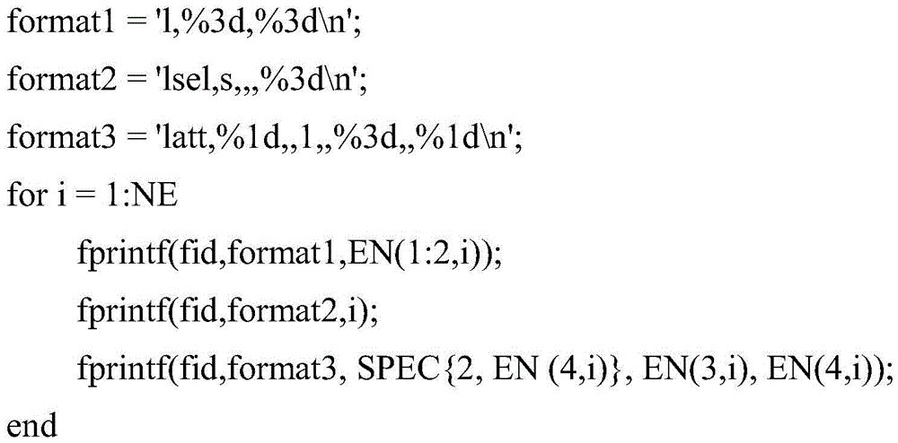
g) grid division:
fprintf(fid,'allsel,all\nlmesh,all\nallsel,all\n');
h) modeling is finished and the file is closed:
fprintf(fid,'finish\n\n');
fclose(fid)。
the following is a detailed description of a finite element model establishing device of a transmission tower provided by the invention.
The invention also provides a power transmission tower finite element model establishing device, which comprises a processor and a memory, wherein the processor comprises:
the memory is used for storing the program codes and transmitting the program codes to the processor;
the processor is used for executing the transmission tower finite element model building method according to the instructions in the program codes.
It is clear to those skilled in the art that, for convenience and brevity of description, the specific working processes of the above-described systems, apparatuses and units may refer to the corresponding processes in the foregoing method embodiments, and are not described herein again.
In the several embodiments provided in the present application, it should be understood that the disclosed system, apparatus and method may be implemented in other manners. For example, the above-described apparatus embodiments are merely illustrative, and for example, the division of the units is only one logical division, and other divisions may be realized in practice, for example, a plurality of units or components may be combined or integrated into another system, or some features may be omitted, or not executed. In addition, the shown or discussed mutual coupling or direct coupling or communication connection may be an indirect coupling or communication connection through some interfaces, devices or units, and may be in an electrical, mechanical or other form.
The units described as separate parts may or may not be physically separate, and parts displayed as units may or may not be physical units, may be located in one place, or may be distributed on a plurality of network units. Some or all of the units can be selected according to actual needs to achieve the purpose of the solution of the embodiment.
In addition, functional units in the embodiments of the present invention may be integrated into one processing unit, or each unit may exist alone physically, or two or more units are integrated into one unit. The integrated unit can be realized in a form of hardware, and can also be realized in a form of a software functional unit.
The integrated unit, if implemented in the form of a software functional unit and sold or used as a stand-alone product, may be stored in a computer readable storage medium. Based on such understanding, the technical solution of the present invention may be embodied in the form of a software product, which is stored in a storage medium and includes instructions for causing a computer device (which may be a personal computer, a server, or a network device) to execute all or part of the steps of the method according to the embodiments of the present invention. And the aforementioned storage medium includes: a U-disk, a removable hard disk, a Read-Only Memory (ROM), a Random Access Memory (RAM), a magnetic disk or an optical disk, and other various media capable of storing program codes.
The above-mentioned embodiments are only used for illustrating the technical solutions of the present invention, and not for limiting the same; although the present invention has been described in detail with reference to the foregoing embodiments, it will be understood by those of ordinary skill in the art that: the technical solutions described in the foregoing embodiments may still be modified, or some technical features may be equivalently replaced; and such modifications or substitutions do not depart from the spirit and scope of the corresponding technical solutions of the embodiments of the present invention.
Claims (7)
1. A transmission tower finite element model building method is characterized by comprising the following steps:
s1, establishing a global coordinate system, and segmenting the power transmission tower according to a given design drawing;
s2, calculating the coordinates of the connection points in each section according to the characteristic structure of the segmented power transmission tower, determining the local number of the connection points and the overall number of the corresponding connection points which are associated with each member in the section, and determining the cross section number of each member; the feature is composed of more than one sub-structure forming a circular array; the substructure comprises a substructure 1, a substructure 2 and a substructure 3, the connection points of the substructure 1 are located at least at two different heights, the connection point types comprise P2, P3, P4 and P5, the connection points of the substructure 2 are located at the same height, the connection point types comprise P1 and P2, the connection points of the substructure 3 are located at least at two different heights different from the substructure 1, the connection point types comprise P2, P3, P4 and P5; the connection point types are specifically: the connecting point of the components on the center line of the height direction of the power transmission tower is defined as a P1 connecting point; the connecting points on the four ridge lines of the power transmission tower outline are defined as P2 connecting points; defining a connecting point on a horizontal plane coordinate axis after projection in the power transmission tower contour surface as a P3 connecting point; defining a connecting point which is positioned in a horizontal plane coordinate system quadrant after projection in the contour plane of the power transmission tower as a P4 connecting point; a connecting point in the power transmission tower, which is not on the ridge line, the profile surface and the center line in the tower height direction, is defined as a P5 connecting point;
s3, determining the reference point coordinates, the reference point local numbers and the corresponding reference point general numbers of the cross section directions of each member according to the local numbers of the connecting points associated with each member, the design drawing and the designated method of the cross section directions of the angle steel members;
s4, generating a member and connecting point association array according to the connecting point local number, the reference point local number and the member cross section number of each member;
s5, determining the connection point total number and the reference point total number corresponding to the connection point association array;
s6, generating a modeling file of the finite element model of the power transmission tower according to the connection point total number, the reference point total number and the component cross section number corresponding to the component and the connection point association array, the connection point coordinates, the reference point coordinates, the given material parameter array and the component cross section array;
s7, importing the modeling file into finite element software to establish a finite element model of the power transmission tower;
the step S2 specifically includes:
acquiring a connection point corresponding to one substructure of the characteristic structure from a design drawing, calculating coordinates and local numbers of the connection points, and acquiring the coordinates and local numbers of the connection points of the remaining substructures forming the annular array through annular array operation;
the component cross-section number for each component is determined from component model specification information associated with each component within the sub-structure.
2. The method for establishing a finite element model of a transmission tower according to claim 1, wherein the step S1 of segmenting the transmission tower specifically comprises:
the power transmission tower is divided into a main structure and auxiliary cross arms, each pair of auxiliary cross arms is used as a subsection, and each characteristic structure is used as a subsection for the main structure along the height direction of the power transmission tower.
3. A transmission tower finite element model building method according to claim 2, wherein the accessory cross arm is composed of two substructures;
the step S2 further includes:
acquiring a connection point corresponding to one substructure of the auxiliary cross arm from a design drawing, calculating coordinates and local numbers of the connection points, judging whether the other substructure of the auxiliary cross arm is symmetrical to the substructure, if so, obtaining the coordinates and the local numbers of the connection points of the substructure forming the annular array through annular array operation, and if not, independently generating the coordinates and the local numbers of the connection points of the other substructure;
the member cross-section number of each member is determined from member model specification information associated with each member within the substructure of the secondary cross-arm.
4. The finite element model building method of a transmission tower according to claim 1, wherein the step S4 specifically comprises:
and taking two connecting point local numbers, one reference point local number and one member cross section number of each member as the first four dimensions of the member and connecting point associated array, and calculating a cross section number rotation array according to the member cross section numbers corresponding to the feature structures with different heights to be used as the fifth dimension of the member and connecting point associated array.
5. The finite element model building method of a transmission tower according to claim 1, wherein the step S5 specifically comprises:
and determining a connection point overall number and a reference point overall number corresponding to the connection point association array according to the connection point local number and the reference point local number of the connection point association array of the component.
6. The finite element model building method of a transmission tower according to claim 1, wherein the step S6 specifically comprises:
creating a modeling file, and generating the following commands in the modeling file:
preprocessing a file header;
setting a beam unit type;
generating a set material attribute and a cross section parameter according to the component cross section array;
connecting the two connecting points into a line in sequence according to the connecting point total numbers corresponding to the first two dimensions in the member and connecting point association array;
selecting the line;
assigning a material type, a unit type, a reference point overall number and a member cross-section number to the member according to the last two dimensions in the member and connection point associated array;
generating and dividing grids;
and finishing the pretreatment.
7. A finite element model building device for a transmission tower, the device comprising a processor and a memory:
the memory is used for storing program codes and transmitting the program codes to the processor;
the processor is configured to execute a transmission tower finite element model building method according to any one of claims 1 to 6 according to instructions in the program code.
Priority Applications (1)
| Application Number | Priority Date | Filing Date | Title |
|---|---|---|---|
| CN201810645612.4A CN108763827B (en) | 2018-06-21 | 2018-06-21 | Transmission tower finite element model establishing method and device |
Applications Claiming Priority (1)
| Application Number | Priority Date | Filing Date | Title |
|---|---|---|---|
| CN201810645612.4A CN108763827B (en) | 2018-06-21 | 2018-06-21 | Transmission tower finite element model establishing method and device |
Publications (2)
| Publication Number | Publication Date |
|---|---|
| CN108763827A CN108763827A (en) | 2018-11-06 |
| CN108763827B true CN108763827B (en) | 2020-11-17 |
Family
ID=63979988
Family Applications (1)
| Application Number | Title | Priority Date | Filing Date |
|---|---|---|---|
| CN201810645612.4A Active CN108763827B (en) | 2018-06-21 | 2018-06-21 | Transmission tower finite element model establishing method and device |
Country Status (1)
| Country | Link |
|---|---|
| CN (1) | CN108763827B (en) |
Families Citing this family (7)
| Publication number | Priority date | Publication date | Assignee | Title |
|---|---|---|---|---|
| CN109711064B (en) * | 2018-12-28 | 2023-04-28 | 上海市建工设计研究总院有限公司 | Method and device for simulating numerical wind tunnel by adopting ABAQUS |
| CN110309622B (en) * | 2019-07-11 | 2023-06-06 | 广东电网有限责任公司 | Power transmission tower structure collapse analysis method |
| CN110334459B (en) * | 2019-07-11 | 2023-05-26 | 广东电网有限责任公司 | Rapid and refined modeling system and method for power transmission tower line system |
| CN113450250B (en) * | 2020-03-25 | 2026-04-14 | 中国电力科学研究院有限公司 | Drawing-based modeling method and system for power transmission tower |
| CN112036061B (en) * | 2020-08-07 | 2024-05-10 | 国网浙江省电力有限公司电力科学研究院 | Finite element modeling and dynamic response analysis method for omnibearing long and short leg tower line system |
| CN112115616B (en) * | 2020-09-21 | 2021-09-24 | 广东电网有限责任公司电力科学研究院 | Dynamic characteristic analysis method and device of power transmission tower |
| CN113094536B (en) * | 2021-04-19 | 2023-10-27 | 国网北京市电力公司 | Lightweight display method and device for transmission poles and towers based on power grid GIM |
Citations (3)
| Publication number | Priority date | Publication date | Assignee | Title |
|---|---|---|---|---|
| JP2003316833A (en) * | 2002-04-25 | 2003-11-07 | Sekisui Chem Co Ltd | Structural analysis method of finite element method, program for executing this structure analysis method, and recording medium recording this program |
| CN103514327A (en) * | 2013-09-27 | 2014-01-15 | 国家电网公司 | Finite element parametric modeling method of power transmission steel pipe pole |
| CN104504167A (en) * | 2014-08-29 | 2015-04-08 | 广西电网公司电力科学研究院 | System and simulation method for transmission tower structure static mechanic analysis |
-
2018
- 2018-06-21 CN CN201810645612.4A patent/CN108763827B/en active Active
Patent Citations (4)
| Publication number | Priority date | Publication date | Assignee | Title |
|---|---|---|---|---|
| JP2003316833A (en) * | 2002-04-25 | 2003-11-07 | Sekisui Chem Co Ltd | Structural analysis method of finite element method, program for executing this structure analysis method, and recording medium recording this program |
| CN103514327A (en) * | 2013-09-27 | 2014-01-15 | 国家电网公司 | Finite element parametric modeling method of power transmission steel pipe pole |
| CN103514327B (en) * | 2013-09-27 | 2016-06-01 | 国家电网公司 | The parametric Finite Element Modeling Method of a kind of steel pipe bar of transmitting electricity |
| CN104504167A (en) * | 2014-08-29 | 2015-04-08 | 广西电网公司电力科学研究院 | System and simulation method for transmission tower structure static mechanic analysis |
Also Published As
| Publication number | Publication date |
|---|---|
| CN108763827A (en) | 2018-11-06 |
Similar Documents
| Publication | Publication Date | Title |
|---|---|---|
| CN108763827B (en) | Transmission tower finite element model establishing method and device | |
| CN105787226B (en) | The parameterized model of four side finite element mesh models is rebuild | |
| Reberol et al. | Quasi-structured quadrilateral meshing in Gmsh--a robust pipeline for complex CAD models | |
| JP2005038219A (en) | Method and program for generating volume data from boundary representation data | |
| CN115330971B (en) | Geometric model lightweight method oriented to rendering performance optimization | |
| CN111310811B (en) | A 3D point cloud classification method for large scenes based on optimal combination of multidimensional features | |
| CN118071960A (en) | Octree mesh encryption and generation method for semiconductor device simulation | |
| Jin et al. | Computing tëichmuller shape space | |
| CN118153450A (en) | A hybrid mesh quality optimization method based on probability model | |
| CN105224748B (en) | A kind of section preprocess method of non-uniform beam finite element model | |
| CN107644139B (en) | A Attribute Mapping Method from CAD Model to CAE Model | |
| CN111915720B (en) | Automatic conversion method from building Mesh model to CityGML model | |
| CN114756980B (en) | Multi-design space coupled aerodynamic shape optimization method and system based on Info-GAN | |
| CN109918829B (en) | Axial mode identification method for structure | |
| CN119272359B (en) | A method, device and medium for generating a lattice structure | |
| CN112346409B (en) | A method for quickly judging point cloud inclusion problems | |
| US20190026399A1 (en) | Analysis model creation assistance device and analysis model creation assistance method | |
| CN103020402A (en) | Modeling method and modeling device | |
| CN119358341A (en) | Method for establishing microscopic finite element model of double-layer reinforced concrete structure | |
| Navarro‐García et al. | High‐order discontinuous Galerkin method for time‐domain electromagnetics on geometry‐independent Cartesian meshes | |
| CN120526086B (en) | Method and system for generating quadrilateral mesh of geometric models based on GPU parallelism | |
| Shepherd | Conforming hexahedral mesh generation via geometric capture methods | |
| CN119693537B (en) | A method, apparatus, electronic device and storage medium for creating a 3D model of a bridge. | |
| CN104504223A (en) | Inside and outside boundary treatment method of isogeometric analysis | |
| CN119336932B (en) | Batch house household processing method based on semantic information |
Legal Events
| Date | Code | Title | Description |
|---|---|---|---|
| PB01 | Publication | ||
| PB01 | Publication | ||
| SE01 | Entry into force of request for substantive examination | ||
| SE01 | Entry into force of request for substantive examination | ||
| GR01 | Patent grant | ||
| GR01 | Patent grant |