CN108698685B - Unmanned aerial vehicle and its frame, kit, assembly method, and operation method - Google Patents
Unmanned aerial vehicle and its frame, kit, assembly method, and operation method Download PDFInfo
- Publication number
- CN108698685B CN108698685B CN201680082409.XA CN201680082409A CN108698685B CN 108698685 B CN108698685 B CN 108698685B CN 201680082409 A CN201680082409 A CN 201680082409A CN 108698685 B CN108698685 B CN 108698685B
- Authority
- CN
- China
- Prior art keywords
- fuselage
- horn
- arm
- assembling
- aerial vehicle
- Prior art date
- Legal status (The legal status is an assumption and is not a legal conclusion. Google has not performed a legal analysis and makes no representation as to the accuracy of the status listed.)
- Active
Links
Images



Classifications
-
- B—PERFORMING OPERATIONS; TRANSPORTING
- B64—AIRCRAFT; AVIATION; COSMONAUTICS
- B64C—AEROPLANES; HELICOPTERS
- B64C39/00—Aircraft not otherwise provided for
- B64C39/02—Aircraft not otherwise provided for characterised by special use
- B64C39/024—Aircraft not otherwise provided for characterised by special use of the remote controlled vehicle type, i.e. RPV
-
- B—PERFORMING OPERATIONS; TRANSPORTING
- B64—AIRCRAFT; AVIATION; COSMONAUTICS
- B64C—AEROPLANES; HELICOPTERS
- B64C1/00—Fuselages; Constructional features common to fuselages, wings, stabilising surfaces or the like
- B64C1/30—Parts of fuselage relatively movable to reduce overall dimensions of aircraft
-
- B—PERFORMING OPERATIONS; TRANSPORTING
- B64—AIRCRAFT; AVIATION; COSMONAUTICS
- B64C—AEROPLANES; HELICOPTERS
- B64C25/00—Alighting gear
- B64C25/32—Alighting gear characterised by elements which contact the ground or similar surface
- B64C25/52—Skis or runners
-
- B—PERFORMING OPERATIONS; TRANSPORTING
- B64—AIRCRAFT; AVIATION; COSMONAUTICS
- B64U—UNMANNED AERIAL VEHICLES [UAV]; EQUIPMENT THEREFOR
- B64U10/00—Type of UAV
- B64U10/10—Rotorcrafts
- B64U10/13—Flying platforms
- B64U10/14—Flying platforms with four distinct rotor axes, e.g. quadcopters
-
- B—PERFORMING OPERATIONS; TRANSPORTING
- B64—AIRCRAFT; AVIATION; COSMONAUTICS
- B64U—UNMANNED AERIAL VEHICLES [UAV]; EQUIPMENT THEREFOR
- B64U30/00—Means for producing lift; Empennages; Arrangements thereof
- B64U30/20—Rotors; Rotor supports
- B64U30/29—Constructional aspects of rotors or rotor supports; Arrangements thereof
- B64U30/293—Foldable or collapsible rotors or rotor supports
-
- B—PERFORMING OPERATIONS; TRANSPORTING
- B64—AIRCRAFT; AVIATION; COSMONAUTICS
- B64U—UNMANNED AERIAL VEHICLES [UAV]; EQUIPMENT THEREFOR
- B64U10/00—Type of UAV
- B64U10/10—Rotorcrafts
-
- B—PERFORMING OPERATIONS; TRANSPORTING
- B64—AIRCRAFT; AVIATION; COSMONAUTICS
- B64U—UNMANNED AERIAL VEHICLES [UAV]; EQUIPMENT THEREFOR
- B64U10/00—Type of UAV
- B64U10/10—Rotorcrafts
- B64U10/13—Flying platforms
-
- B—PERFORMING OPERATIONS; TRANSPORTING
- B64—AIRCRAFT; AVIATION; COSMONAUTICS
- B64U—UNMANNED AERIAL VEHICLES [UAV]; EQUIPMENT THEREFOR
- B64U2101/00—UAVs specially adapted for particular uses or applications
- B64U2101/30—UAVs specially adapted for particular uses or applications for imaging, photography or videography
-
- B—PERFORMING OPERATIONS; TRANSPORTING
- B64—AIRCRAFT; AVIATION; COSMONAUTICS
- B64U—UNMANNED AERIAL VEHICLES [UAV]; EQUIPMENT THEREFOR
- B64U30/00—Means for producing lift; Empennages; Arrangements thereof
- B64U30/20—Rotors; Rotor supports
-
- B—PERFORMING OPERATIONS; TRANSPORTING
- B64—AIRCRAFT; AVIATION; COSMONAUTICS
- B64U—UNMANNED AERIAL VEHICLES [UAV]; EQUIPMENT THEREFOR
- B64U50/00—Propulsion; Power supply
- B64U50/10—Propulsion
- B64U50/19—Propulsion using electrically powered motors
-
- B—PERFORMING OPERATIONS; TRANSPORTING
- B64—AIRCRAFT; AVIATION; COSMONAUTICS
- B64U—UNMANNED AERIAL VEHICLES [UAV]; EQUIPMENT THEREFOR
- B64U60/00—Undercarriages
- B64U60/50—Undercarriages with landing legs
-
- B—PERFORMING OPERATIONS; TRANSPORTING
- B64—AIRCRAFT; AVIATION; COSMONAUTICS
- B64U—UNMANNED AERIAL VEHICLES [UAV]; EQUIPMENT THEREFOR
- B64U80/00—Transport or storage specially adapted for UAVs
Landscapes
- Engineering & Computer Science (AREA)
- Aviation & Aerospace Engineering (AREA)
- Mechanical Engineering (AREA)
- Remote Sensing (AREA)
- Toys (AREA)
- Automatic Assembly (AREA)
- Control Of Position, Course, Altitude, Or Attitude Of Moving Bodies (AREA)
- Air Bags (AREA)
- Motorcycle And Bicycle Frame (AREA)
- Agricultural Machines (AREA)
- Manipulator (AREA)
- Forklifts And Lifting Vehicles (AREA)
Abstract
一种无人飞行器(100)的机架,包括机身(20)以及机臂(31)。所述机臂(31)可转动地连接于所述机身(20),使所述机臂(31)能够相对于所述机身(20)选择性地处于折叠状态或者展开状态。其中,在所述折叠状态与所述展开状态时,所述机臂(31)的自由端相较于所述机身(20)的底部的高度以及相较于所述机身(20)的侧表面(20‑3、20‑4)的距离均不相同。本发明还涉及一种包括所述机架的无人飞行器(100)、用于组装所述无人飞行器(100)的套件,以及所述无人飞行器(100)的组装方法和操作方法。

A frame of an unmanned aerial vehicle (100) comprises a fuselage (20) and an arm (31). The machine arm (31) is rotatably connected to the body (20), so that the machine arm (31) can be selectively folded or unfolded relative to the body (20). Wherein, in the folded state and the unfolded state, the height of the free end of the arm (31) compared to the bottom of the body (20) and the height of the free end of the body (20) The side surfaces (20‑3, 20‑4) are all different distances. The invention also relates to an unmanned aerial vehicle (100) comprising the frame, a kit for assembling the unmanned aerial vehicle (100), and a method of assembling and operating the unmanned aerial vehicle (100).
Description
技术领域technical field
本发明涉及无人飞行器领域,特别涉及一种可折叠的无人飞行器及其机架、套件、组装方法、以及操作方法。The present invention relates to the field of unmanned aerial vehicles, in particular to a foldable unmanned aerial vehicle and its frame, kit, assembly method, and operation method.
背景技术Background technique
小型无人飞行器由于制造成本相对较低,且能够提供轻巧、灵活的低空、低速以及悬停飞行,体积小易于携带,如今已被广泛应用到各种民用领域,特别是各种地理测绘、航拍以及监测等领域。然而,现有的无人飞行器的机臂一般都是不可折叠的,因此不利于无人飞行器体积的小型化设计。此外,为了使无人飞行器降落时能够站立并保护机身,目前的无人飞行器一般都设有突出于所述机身的脚架。然而,由于脚架突出于机身,既不利于无人飞行器体积的小型化设计,还影响无人飞行器的外观。因此,如何在无人飞行器处于非使用状态下时,减小由所述机臂、脚架而导致的机身体积增大,是业界亟待解决的一个技术难题。Small unmanned aerial vehicles have been widely used in various civil fields, especially various geographic mapping, aerial photography, due to their relatively low manufacturing cost, light and flexible low-altitude, low-speed and hovering flight, small size and easy to carry. and monitoring. However, the arms of the existing unmanned aerial vehicles are generally not foldable, which is not conducive to the miniaturized design of the unmanned aerial vehicle. In addition, in order to make the unmanned aerial vehicle stand and protect the fuselage when landing, the current unmanned aerial vehicle is generally provided with a tripod protruding from the fuselage. However, since the tripod protrudes from the fuselage, it is not conducive to the miniaturized design of the UAV, but also affects the appearance of the UAV. Therefore, how to reduce the increase in the size of the fuselage caused by the arms and the tripod when the unmanned aerial vehicle is not in use is a technical problem to be solved urgently in the industry.
发明内容SUMMARY OF THE INVENTION
有鉴于此,有必要提出一种可折叠的机架以及无人飞行器,还有必要提供一种用于组装所述无人飞行器的套件,以及所述无人飞行器的组装方法和操作方法,以解决上述缩小无人飞行器在非使用状态下的体积的问题。In view of this, it is necessary to propose a foldable frame and an unmanned aerial vehicle, and it is also necessary to provide a kit for assembling the unmanned aerial vehicle, as well as an assembling method and an operating method of the unmanned aerial vehicle, so as to Solve the above problem of reducing the size of the unmanned aerial vehicle when it is not in use.
一种无人飞行器的机架,包括机身以及机臂,所述机臂可转动地连接于所述机身,使所述机臂能够相对于所述机身选择性地处于折叠状态或者展开状态;A frame of an unmanned aerial vehicle includes a fuselage and an arm, the arm is rotatably connected to the fuselage, so that the arm can be selectively folded or unfolded relative to the fuselage state;
其中,在所述折叠状态与所述展开状态时,所述机臂的自由端相较于所述机身的底部的高度以及相较于所述机身的侧表面的距离均不相同。Wherein, in the folded state and the unfolded state, the height of the free end of the arm compared to the bottom of the fuselage and the distance from the side surface of the fuselage are different.
进一步地,所述机臂的自由端在所述折叠状态时相较于所述机身的底部的高度,大于在所述展开状态时相较于所述机身的底部的高度。Further, the height of the free end of the machine arm compared to the bottom of the fuselage in the folded state is greater than the height of the bottom of the fuselage in the unfolded state.
进一步地,所述机架还包括连接于所述机臂的自由端的脚架,所述脚架用于在所述无人飞行器的着陆过程中保护所述机身不受到撞击以及在所述无人飞行器着陆于一支撑面时支撑所述机身;Further, the frame further includes a tripod connected to the free end of the arm, and the tripod is used to protect the fuselage from being hit during the landing of the unmanned aerial vehicle and to protect the fuselage from being hit during the landing of the unmanned aerial vehicle. supporting the fuselage when the human aircraft lands on a support surface;
其中,在所述折叠状态与所述展开状态时,所述脚架相较于所述机身的底部的高度不相同。Wherein, in the folded state and the unfolded state, the height of the tripod is different from that of the bottom of the fuselage.
进一步地,所述脚架在所述折叠状态时相较于所述机身的侧表面的距离,小于在所述展开状态时相较于所述机身的侧表面的距离。Further, the distance of the foot stand from the side surface of the fuselage in the folded state is smaller than the distance from the side surface of the fuselage in the unfolded state.
进一步地,所述脚架的自由端在所述折叠状态时相较于所述机身的底部的高度,大于在所述展开状态时相较于所述机身的底部的高度。Further, the height of the free end of the foot stand compared to the bottom of the fuselage in the folded state is greater than the height of the bottom of the fuselage in the unfolded state.
进一步地,所述脚架在所述机臂位于所述展开位置时朝向所述机身的底部并凸出于所述机身的底部。Further, when the arm is in the unfolded position, the stand faces the bottom of the fuselage and protrudes from the bottom of the fuselage.
进一步地,所述机臂包括第一机臂,所述第一机臂相对于所述机身的侧表面绕第一转动轴转动,其中,所述第一转动轴相对于所述无人飞行器的偏航轴呈第一预定倾斜角度,且所述第一转动轴大致平行于所述无人飞行器的偏航轴与横滚轴所确定的平面,使得所述第一机臂自所述折叠状态转动以进入所述展开状态的同时,所述第一机臂的自由端相较于所述机身的底部的高度降低。Further, the arm includes a first arm, and the first arm rotates relative to the side surface of the fuselage around a first rotation axis, wherein the first rotation axis is relative to the unmanned aerial vehicle The yaw axis of the unmanned aerial vehicle is at a first predetermined inclination angle, and the first rotation axis is substantially parallel to the plane determined by the yaw axis and the roll axis of the unmanned aerial vehicle, so that the first arm is folded from the When the state is rotated to enter the unfolded state, the height of the free end of the first arm is lower than that of the bottom of the fuselage.
进一步地,所述第一机臂能够相对于所述机身选择性地保持于预定的折叠位置以及预定的展开位置,且能够在所述折叠位置与所述展开位置之间转动,其中,当所述第一机臂位于所述折叠位置时,所述第一机臂的自由端紧贴所述机身,当所述第一机臂位于所述展开位置时,所述第一机臂的自由端远离所述机身。Further, the first arm can be selectively held in a predetermined folded position and a predetermined unfolded position relative to the fuselage, and can be rotated between the folded position and the unfolded position, wherein when When the first arm is at the folded position, the free end of the first arm is close to the fuselage, and when the first arm is at the unfolded position, the free end of the first arm is close to the fuselage. The free end is remote from the fuselage.
进一步地,所述机架包括多个所述第一机臂,多个所述第一机臂分别连接于所述机身的不同的侧表面,或者,两两相对连接于所述机身的同一侧表面的相对两端,或者,两两相对连接于所述机身的相对两侧表面。Further, the frame includes a plurality of the first arms, and the plurality of the first arms are respectively connected to different side surfaces of the fuselage, or, two oppositely connected to the fuselage. Opposite ends of the same side surface, or, in pairs, are connected to the opposite side surfaces of the fuselage.
进一步地,所述机臂包括第二机臂,所述第二机臂相对于所述机身的侧表面绕第二转动轴转动,其中,所述第二转动轴相对于所述无人飞行器的横滚轴呈第二预定倾斜角度,且所述第二转动轴大致垂直于所述无人飞行器的偏航轴,使得所述第二机臂自所述折叠状态转动以进入所述展开状态的同时,所述第二机臂相较于所述机身翻转180度,使所述第二机臂朝向所述机身的顶部的表面转为朝向所述机身的底部。Further, the arm includes a second arm, and the second arm rotates about a second rotation axis relative to the side surface of the fuselage, wherein the second rotation axis is relative to the unmanned aerial vehicle The roll axis is at a second predetermined inclination angle, and the second rotation axis is substantially perpendicular to the yaw axis of the UAV, so that the second arm rotates from the folded state to enter the unfolded state At the same time, the second arm is turned 180 degrees relative to the fuselage, so that the surface of the second arm facing the top of the fuselage is turned toward the bottom of the fuselage.
进一步地,所述第二机臂能够相对于所述机身选择性地保持于预定的折叠位置以及预定的展开位置,且能够在所述折叠位置与所述展开位置之间转动,其中,当所述第二机臂位于所述折叠位置时,所述第二机臂的自由端紧贴所述机身,当所述第二机臂位于所述展开位置时,所述第二机臂的自由端远离所述机身。Further, the second arm can be selectively held in a predetermined folded position and a predetermined unfolded position relative to the fuselage, and can be rotated between the folded position and the unfolded position, wherein when When the second arm is in the folded position, the free end of the second arm is close to the fuselage, and when the second arm is in the unfolded position, the free end of the second arm is in close contact with the fuselage. The free end is remote from the fuselage.
进一步地,所述机架包括多个所述第二机臂,多个所述第二机臂分别连接于所述机身的不同的侧表面,或者,两两相对连接于所述机身的同一侧表面的相对两端,或者,两两相对连接于所述机身的相对两侧表面。Further, the frame includes a plurality of the second arms, and the plurality of the second arms are respectively connected to different side surfaces of the fuselage, or, two oppositely connected to the fuselage. Opposite ends of the same side surface, or, in pairs, are connected to the opposite side surfaces of the fuselage.
进一步地,所述机臂的自由端用于连接动力装置以及脚架,所述动力装置用于提供飞行动力,所述脚架用于在所述无人飞行器的着陆过程中保护所述机身不受到撞击以及在所述无人飞行器着陆于一支撑面时支撑所述机身;所述动力装置与所述脚架分别位于所述机臂的自由端的相对两侧,所述脚架在所述机臂位于所述展开位置时凸出于所述机身的底部。Further, the free end of the arm is used to connect a power device and a tripod, the power device is used to provide flight power, and the tripod is used to protect the fuselage during the landing process of the UAV not be impacted and support the fuselage when the unmanned aerial vehicle lands on a support surface; the power device and the foot stand are respectively located on opposite sides of the free end of the arm, and the foot stand is located at the The arm protrudes from the bottom of the fuselage when it is in the unfolded position.
进一步地,所述机臂包括第一机臂以及第二机臂,所述第一机臂绕第一转动轴在同一平面上转动,使得连接于所述第一机臂的所述脚架以及所述动力装置的朝向在所述第一机臂的转动过程中均保持不变;所述第二机臂绕第二转动轴沿圆锥面旋转,使得所述第二机臂自所述折叠状态转动以进入所述展开状态的同时,所述第二机臂相较于所述机身翻转180度,并使得连接于所述第二机臂的所述脚架以及所述动力装置的朝向在所述第二机臂的转动过程中也跟随所述第二机臂翻转180度。Further, the machine arm includes a first machine arm and a second machine arm, and the first machine arm rotates on the same plane around the first rotation axis, so that the tripod connected to the first machine arm and the The orientation of the power device remains unchanged during the rotation of the first arm; the second arm rotates along the conical surface around the second rotation axis, so that the second arm is folded from the folded state While rotating to enter the unfolded state, the second arm is turned 180 degrees relative to the fuselage, so that the legs connected to the second arm and the power device are oriented in the During the rotation of the second machine arm, the second machine arm also turns 180 degrees with the second machine arm.
进一步地,所述动力装置包括推进单元,在所述折叠状态时,所述第一机臂将所连接的所述推进单元搁置于所述机身的顶部,所述第二机臂将所连接的所述推进单元搁置于所述机身的底部。Further, the power device includes a propulsion unit, in the folded state, the first arm rests the connected propulsion unit on the top of the fuselage, and the second arm places the connected propulsion unit on top of the fuselage. The propulsion unit rests on the bottom of the fuselage.
进一步地,所述第一机臂以及所述第二机臂分别连接于所述机身的同一侧表面的相对两端,且所述第一机臂与所述第二机臂上下错位,使所述第一机臂与所述第二机臂在所述折叠状态时能够相互扣合在一起。Further, the first arm and the second arm are respectively connected to opposite ends of the same side surface of the fuselage, and the first arm and the second arm are displaced up and down, so that the The first arm and the second arm can be fastened together in the folded state.
进一步地,所述机身包括位于所述无人飞行器的横滚轴方向的一端的头部以及位于所述横滚轴方向的另一端的尾部,所述无人飞行器包括连接于所述机身的头部或靠近所述头部的至少一对所述机臂,以及连接于所述机身的尾部或靠近所述尾部的至少一对所述机臂。Further, the fuselage includes a head located at one end in the direction of the roll axis of the unmanned aerial vehicle and a tail located at the other end in the direction of the roll axis, and the unmanned aerial vehicle includes a head connected to the fuselage. at least a pair of said arms at the head of the fuselage or close to the head, and at least a pair of arms connected to the tail of the fuselage or close to the tail.
进一步地,所述机架还包括设置于所述机身上的转动机构,所述转动机构将所述机身分为两部分,且使所述机身的其中一部分能够相对于另一部分绕所述转动机构的第三转动轴旋转180度,并使连接于所述机身的其中一部分的飞行组件相对连接于所述机身的另一部分的飞行组件旋转180度,其中,所述第三转动轴大致平行于所述无人飞行器的横滚轴。Further, the frame further includes a rotating mechanism disposed on the fuselage, the rotating mechanism divides the fuselage into two parts, and enables one part of the fuselage to be able to circle around the other part relative to the other part. The third rotation axis of the rotating mechanism rotates 180 degrees, and the flying component connected to one part of the fuselage rotates 180 degrees relative to the flying component connected to the other part of the fuselage, wherein the third rotation The axis is substantially parallel to the roll axis of the UAV.
进一步地,所述机臂的自由端还用于连接动力装置,所述动力装置用于提供飞行动力,所述动力装置至少包括推进单元,连接于所述机身的两部分的所述机臂在所述折叠状态时分别将相应的推进单元搁置于所述机身的顶部和底部。Further, the free end of the arm is also used to connect a power device, the power device is used to provide flight power, the power device at least includes a propulsion unit, and the arms connected to the two parts of the fuselage The corresponding propulsion units are rested on the top and bottom of the fuselage, respectively, in the folded state.
进一步地,所述机臂的自由端还用于连接动力装置,所述动力装置用于提供飞行动力,所述动力装置包括推进单元,所述机臂的自由端附近设有转动机构,所述转动机构用于在所述折叠位置时转动所述机臂的自由端,使所述推进单元搁置于所述机身的侧表面。Further, the free end of the arm is also used to connect a power device, the power device is used to provide flight power, the power device includes a propulsion unit, a rotating mechanism is provided near the free end of the arm, and the The rotating mechanism is used for rotating the free end of the machine arm in the folded position, so that the propulsion unit rests on the side surface of the fuselage.
进一步地,所述脚架还用于给所述无人飞行器的通信天线提供附设空间。Further, the tripod is also used to provide an attachment space for the communication antenna of the unmanned aerial vehicle.
进一步地,所述脚架相对于所连接的机臂的长度方向呈非正交角度。Further, the tripod is at a non-orthogonal angle with respect to the length direction of the connected arm.
进一步地,所述脚架能够相对于所连接的机臂折叠至贴附于所连接的机臂上。Further, the foot stand can be folded relative to the connected machine arm to be attached to the connected machine arm.
进一步地,所述机身上还包括转动限位结构,所述转动限位结构用于与所述机臂连接,并限定所述机臂的转动角度。Further, the fuselage further includes a rotation limiting structure, and the rotation limiting structure is used for connecting with the machine arm and limiting the rotation angle of the machine arm.
进一步地,所述机身上还包括锁定结构,所述锁定结构用于与所述机臂连接,并在所述展开状态下使所述机臂能够保持于预定的展开位置,以及在所述折叠状态下使所述机臂能够保持于预定的折叠位置。Further, the fuselage further includes a locking structure, the locking structure is used for connecting with the arm, and in the unfolded state, the arm can be kept in a predetermined unfolded position, and in the unfolded state In the folded state, the machine arm can be kept in a predetermined folded position.
进一步地,所述机身上还包括弹性件,所述弹性件用于与所述机臂连接,并在所述机臂相对于所述机身折叠到第一预定位置时驱使所述机臂自动缩回到预定的折叠位置。Further, the fuselage further includes an elastic piece, the elastic piece is used for connecting with the machine arm and driving the machine arm when the machine arm is folded to a first predetermined position relative to the machine body Automatically retracts to the predetermined folded position.
进一步地,所述机身上还包括弹性件,所述弹性件用于与所述机臂连接,并在所述机臂相对于所述机身展开到第二预定位置时驱使所述机臂自动展开到预定的展开位置。Further, the fuselage further includes an elastic piece, the elastic piece is used for connecting with the machine arm and driving the machine arm when the machine arm is unfolded to a second predetermined position relative to the fuselage Automatically expand to the predetermined expansion position.
进一步地,所述机身上还设有第一安装部,所述第一机臂安装于所述第一安装部上。Further, the fuselage is further provided with a first mounting portion, and the first arm is mounted on the first mounting portion.
进一步地,所述第一安装部凸设于所述机身上。Further, the first mounting portion is protrudingly arranged on the fuselage.
进一步地,所述机身上还设有导向槽,所述第一机臂安装于所述导向槽中,所述第一机臂位于所述折叠位置时收容于所述导向槽中。Further, the body is further provided with a guide groove, the first machine arm is installed in the guide groove, and the first machine arm is accommodated in the guide groove when it is in the folded position.
进一步地,所述机身上还设有第二安装部,所述第二机臂安装于所述第二安装部上。Further, the fuselage is further provided with a second mounting portion, and the second arm is mounted on the second mounting portion.
进一步地,所述第二安装部凸设于所述机身上。Further, the second mounting portion is protruded on the fuselage.
一种无人飞行器,包括:An unmanned aerial vehicle, comprising:
上述各实施例所述的机架,所述机架包括机身和机臂;以及The frame according to the above embodiments, the frame includes a fuselage and an arm; and
承载在所述机臂的动力装置,所述动力装置用于提供飞行动力。A power unit carried on the arm, the power unit is used to provide flight power.
进一步地,所述无人飞行器还包括飞行控制器,所述飞行控制器用于控制所述无人飞行器的飞行状态。Further, the unmanned aerial vehicle further includes a flight controller, and the flight controller is used to control the flight state of the unmanned aerial vehicle.
进一步地,在所述折叠状态与所述展开状态时,所述动力装置相较于所述机身的底部的高度以及相较于所述机身的侧表面的距离均不相同。Further, in the folded state and the unfolded state, the height of the power device compared to the bottom of the fuselage and the distance from the side surface of the fuselage are different.
进一步地,所述动力装置至少包括致动器以及推进单元,所述推进单元通过所述致动器连接至相应机臂,所述致动器用于带动所述推进单元转动,以提供所述无人飞行器的升力。Further, the power device at least includes an actuator and a propulsion unit, the propulsion unit is connected to a corresponding arm through the actuator, and the actuator is used to drive the propulsion unit to rotate, so as to provide the lift of a human aircraft.
进一步地,所述机身上还设有收容部,所述收容部与位于预定的折叠位置时的致动器相对,所述收容部用于收容所述致动器的部分结构。Further, the fuselage is further provided with an accommodating portion, the accommodating portion is opposite to the actuator at a predetermined folding position, and the accommodating portion is used for accommodating a part of the structure of the actuator.
进一步地,所述推进单元为螺旋桨,包括至少两片桨叶,所述推进单元的桨叶能够折叠在一起。Further, the propulsion unit is a propeller, comprising at least two blades, and the blades of the propulsion unit can be folded together.
一种无人飞行器,包括机身以及用于提供飞行动力的飞行组件,所述飞行组件可活动地连接于所述机身,使所述飞行组件能够相对于所述机身选择性地处于折叠状态或者展开状态;An unmanned aerial vehicle includes a fuselage and a flying assembly for providing flight power, the flying assembly is movably connected to the fuselage so that the flying assembly can be selectively folded relative to the fuselage state or expanded state;
其中,在所述折叠状态与所述展开状态时,所述飞行组件相较于所述机身的底部的高度以及相较于所述机身的侧表面的距离均不相同。Wherein, in the folded state and the unfolded state, the height of the flying assembly compared to the bottom of the fuselage and the distance from the side surface of the fuselage are different.
一种用于组装成无人飞行器的套件,包括:A kit for assembly into an unmanned aerial vehicle, comprising:
无人飞行器的机身;以及The fuselage of the unmanned aerial vehicle; and
用于提供飞行动力的飞行组件;Flight components used to provide flight power;
其中,按照组装操作指示在所述机身上组装所述飞行组件,使得组装后的所述飞行组件可活动地连接于所述机身,并使所述飞行组件能够相对于所述机身选择性地处于折叠状态或者展开状态;Wherein, the flying assembly is assembled on the fuselage according to the assembly operation instructions, so that the assembled flying assembly can be movably connected to the fuselage, and the flying assembly can be selected relative to the fuselage is naturally folded or unfolded;
其中,在所述折叠状态与所述展开状态时,所述飞行组件相较于所述机身的底部的高度以及相较于所述机身的侧表面的距离均不相同。Wherein, in the folded state and the unfolded state, the height of the flying assembly compared to the bottom of the fuselage and the distance from the side surface of the fuselage are different.
进一步地,所述飞行组件包括机臂,组装后的所述机臂可转动地连接于所述机身的侧表面,使所述机臂能够相对于所述机身选择性地处于折叠状态或者展开状态。Further, the flying assembly includes an arm, and the assembled arm is rotatably connected to the side surface of the fuselage, so that the arm can be selectively folded or folded relative to the fuselage. Expanded state.
进一步地,在所述折叠状态与所述展开状态时,所述机臂的自由端相较于所述机身的底部的高度以及相较于所述机身的侧表面的距离均不相同。Further, in the folded state and the unfolded state, the height of the free end of the machine arm compared to the bottom of the fuselage and the distance from the side surface of the fuselage are different.
进一步地,所述机臂的自由端在所述折叠状态时相较于所述机身的侧表面的距离,小于在所述展开状态时相较于所述机身的侧表面的距离。Further, the distance between the free end of the machine arm and the side surface of the fuselage in the folded state is smaller than the distance from the side surface of the fuselage in the unfolded state.
进一步地,所述机臂的自由端在所述折叠状态时相较于所述机身的底部的高度,大于在所述展开状态时相较于所述机身的底部的高度。Further, the height of the free end of the machine arm compared to the bottom of the fuselage in the folded state is greater than the height of the bottom of the fuselage in the unfolded state.
进一步地,所述飞行组件还包括脚架,组装后的所述脚架连接于所述机臂的自由端,其中,所述脚架用于在所述无人飞行器的着陆过程中保护所述机身不受到撞击以及在所述无人飞行器着陆于一支撑面时支撑所述机身;Further, the flying assembly further includes a tripod, and the assembled tripod is connected to the free end of the arm, wherein the tripod is used to protect the unmanned aerial vehicle during the landing process. The fuselage is not impacted and supports the fuselage when the UAV lands on a support surface;
其中,在所述折叠状态与所述展开状态时,所述脚架相较于所述机身的底部的高度以及相较于所述机身的侧表面的距离均不相同。Wherein, in the folded state and the unfolded state, the height of the foot stand compared to the bottom of the fuselage and the distance from the side surface of the fuselage are different.
进一步地,组装后的所述脚架在所述折叠状态时相较于所述机身的侧表面的距离,小于在所述展开状态时相较于所述机身的侧表面的距离。Further, the distance of the assembled stand from the side surface of the fuselage in the folded state is smaller than the distance from the side surface of the fuselage in the unfolded state.
进一步地,组装后的所述脚架的自由端在所述折叠状态时相较于所述机身的底部的高度,大于在所述展开状态时相较于所述机身的底部的高度。Further, the height of the free end of the assembled foot stand compared to the bottom of the fuselage in the folded state is greater than the height of the bottom of the fuselage in the unfolded state.
进一步地,组装后的所述脚架在所述机臂位于所述展开位置时凸出于所述机身的底部。Further, the assembled foot stand protrudes from the bottom of the fuselage when the arm is in the unfolded position.
进一步地,所述飞行组件还包括用于提供飞行动力的动力装置,组装后的所述动力装置连接于所述机臂的自由端,其中,在所述折叠状态与所述展开状态时,所述动力装置相较于所述机身的底部的高度以及相较于所述机身的侧表面的距离均不相同。Further, the flying assembly further includes a power device for providing flight power, the assembled power device is connected to the free end of the arm, wherein, in the folded state and the unfolded state, the The heights of the power plant from the bottom of the fuselage and the distance from the side surfaces of the fuselage are different.
进一步地,组装后的所述动力装置在所述折叠状态时相较于所述机身的侧表面的距离,小于在所述展开状态时相较于所述机身的侧表面的距离。Further, the distance of the assembled power device from the side surface of the fuselage in the folded state is smaller than the distance from the side surface of the fuselage in the unfolded state.
进一步地,组装后的所述动力装置在所述折叠状态时相较于所述机身的底部的高度,大于在所述展开状态时相较于所述机身的底部的高度。Further, the height of the assembled power unit compared to the bottom of the fuselage in the folded state is greater than the height of the bottom of the fuselage in the unfolded state.
进一步地,组装后的所述动力装置在所述折叠状态时相较于所述机身的底部的高度,小于在所述展开状态时相较于所述机身的底部的高度。Further, the height of the assembled power unit compared to the bottom of the fuselage in the folded state is smaller than the height of the bottom of the fuselage in the unfolded state.
进一步地,所述机臂包括第一机臂,组装后的所述第一机臂相对于所述机身的侧表面绕第一转动轴转动,其中,所述第一转动轴相对于所述无人飞行器的偏航轴呈第一预定倾斜角度,且所述第一转动轴大致平行于所述无人飞行器的偏航轴与横滚轴所确定的平面,使得所述第一机臂自所述折叠状态转动以进入所述展开状态的同时,所述第一机臂的自由端相较于所述机身底部的高度降低。Further, the arm includes a first arm, and the assembled first arm rotates relative to the side surface of the fuselage around a first rotation axis, wherein the first rotation axis is relative to the The yaw axis of the unmanned aerial vehicle is at a first predetermined inclination angle, and the first rotation axis is substantially parallel to the plane determined by the yaw axis and the roll axis of the unmanned aerial vehicle, so that the first arm is automatically When the folded state is rotated to enter the unfolded state, the height of the free end of the first arm is lower than that of the bottom of the fuselage.
进一步地,组装后的所述第一机臂能够相对于所述机身选择性地保持于预定的折叠位置以及预定的展开位置,且能够在所述折叠位置与所述展开位置之间转动,其中,当所述第一机臂位于所述折叠位置时,所述第一机臂的自由端紧贴所述机身,当所述第一机臂位于所述展开位置时,所述第一机臂的自由端远离所述机身。Further, the assembled first arm can be selectively held in a predetermined folding position and a predetermined unfolding position relative to the fuselage, and can be rotated between the folding position and the unfolding position, Wherein, when the first arm is in the folded position, the free end of the first arm is in close contact with the fuselage, and when the first arm is in the unfolded position, the first arm The free ends of the arms are remote from the fuselage.
进一步地,所述套件包括多个所述第一机臂,组装后的多个所述第一机臂分别连接于所述机身的不同的侧表面,或者,两两相对连接于所述机身的同一侧表面的相对两端,或者,两两相对连接于所述机身的相对两侧表面。Further, the kit includes a plurality of the first arms, and the assembled first arms are respectively connected to different side surfaces of the fuselage, or are connected to the machine in pairs opposite to each other. The opposite ends of the same side surface of the fuselage, or, two opposite sides of the fuselage are connected to the opposite side surfaces of the fuselage.
进一步地,所述机臂包括第二机臂,组装后的所述第二机臂相对于所述机身的侧表面绕第二转动轴转动,其中,所述第二转动轴相对于所述无人飞行器的横滚轴呈第二预定倾斜角度,且所述第二转动轴大致垂直于所述偏航轴,使得所述第二机臂自所述折叠状态转动以进入所述展开状态的同时,所述第二机臂相较于所述机身翻转180度,使所述第二机臂朝向所述机身的顶部的表面转为朝向所述机身的底部。Further, the machine arm includes a second machine arm, and the assembled second machine arm rotates relative to the side surface of the fuselage around a second rotation axis, wherein the second rotation axis is relative to the The roll axis of the unmanned aerial vehicle is at a second predetermined inclination angle, and the second rotation axis is substantially perpendicular to the yaw axis, so that the second arm rotates from the folded state to enter the unfolded state. At the same time, the second arm is turned 180 degrees relative to the fuselage, so that the surface of the second arm facing the top of the fuselage is turned toward the bottom of the fuselage.
进一步地,组装后的所述第二机臂能够相对于所述机身选择性地保持于预定的折叠位置以及预定的展开位置,且能够在所述折叠位置与所述展开位置之间转动,其中,当所述第二机臂位于所述折叠位置时,所述第二机臂的自由端紧贴所述机身,当所述第二机臂位于所述展开位置时,所述第二机臂的自由端远离所述机身。Further, the assembled second arm can be selectively maintained at a predetermined folding position and a predetermined unfolding position relative to the fuselage, and can be rotated between the folding position and the unfolding position, Wherein, when the second arm is in the folded position, the free end of the second arm is in close contact with the fuselage, and when the second arm is in the unfolded position, the second arm The free ends of the arms are remote from the fuselage.
进一步地,所述套件包括多个所述第二机臂,组装后的多个所述第二机臂分别连接于所述机身的不同的侧表面,或者,两两相对连接于所述机身的同一侧表面的相对两端,或者,两两相对连接于所述机身的相对两侧表面上。Further, the kit includes a plurality of the second arms, and the assembled plurality of the second arms are respectively connected to different side surfaces of the fuselage, or are connected to the machine in pairs opposite to each other. The opposite ends of the same side surface of the fuselage, or two opposite sides of the fuselage are connected to the opposite side surfaces of the fuselage.
进一步地,所述飞行组件还包括动力装置以及脚架,所述动力装置用于提供飞行动力,所述脚架用于在所述无人飞行器的着陆过程中保护所述机身不受到撞击以及在所述无人飞行器着陆于一支撑面时支撑所述机身;组装后的所述动力装置与所述脚架分别位于所述机臂的自由端的相对两侧,其中,所述脚架在所述机臂位于所述展开位置时凸出于所述机身的底部。Further, the flight assembly also includes a power device and a tripod, the power device is used to provide flight power, and the tripod is used to protect the fuselage from being hit during the landing process of the UAV and Supporting the fuselage when the unmanned aerial vehicle is landed on a support surface; the assembled power device and the legs are respectively located on opposite sides of the free end of the arm, wherein the legs are on The arm protrudes from the bottom of the fuselage when the machine arm is in the unfolded position.
进一步地,所述机臂包括第一机臂以及第二机臂,组装后的所述第一机臂绕第一转动轴在同一平面上转动,使得连接于所述第一机臂的所述脚架以及所述动力装置的朝向在所述第一机臂的转动过程中均保持不变;组装后的所述第二机臂绕第二转动轴沿圆锥面旋转,使得所述第二机臂自所述折叠状态转动以进入所述展开状态的同时,所述第二机臂相较于所述机身翻转180度,并使得连接于所述第二机臂的所述脚架以及所述动力装置的朝向在所述第二机臂的转动过程中也跟随所述第二机臂翻转180度。Further, the arm includes a first arm and a second arm, and the assembled first arm rotates on the same plane around the first rotation axis, so that the first arm connected to the first arm rotates on the same plane. The orientation of the tripod and the power device remains unchanged during the rotation of the first arm; the assembled second arm rotates along the conical surface around the second rotation axis, so that the second arm rotates along the conical surface. When the arm is rotated from the folded state to enter the unfolded state, the second arm is turned 180 degrees relative to the fuselage, so that the tripod connected to the second arm and the The orientation of the power device also turns 180 degrees with the second arm during the rotation of the second arm.
进一步地,所述动力装置包括推进单元,在所述折叠状态时,所述第一机臂将所连接的推进单元搁置于所述机身的顶部,所述第二机臂将所连接的推进单元搁置于所述机身的底部。Further, the power unit includes a propulsion unit, in the folded state, the first arm rests the connected propulsion unit on the top of the fuselage, and the second arm rests the connected propulsion unit The unit rests on the bottom of the fuselage.
进一步地,组装后的所述第一机臂以及所述第二机臂分别连接于所述机身的同一侧表面的相对两端,且所述第一机臂与所述第二机臂上下错位,使所述第一机臂与所述第二机臂在所述折叠状态时能够相互扣合在一起。Further, the assembled first arm and the second arm are respectively connected to opposite ends of the same side surface of the fuselage, and the first arm and the second arm are up and down The dislocation enables the first arm and the second arm to be fastened together in the folded state.
进一步地,所述机身包括位于所述无人飞行器的横滚轴一端的头部以及位于所述横滚轴另一端的尾部,所述套件包括连接于所述机身的头部或靠近所述头部的至少一对所述机臂,以及连接于所述机身的尾部或靠近所述尾部的至少一对所述机臂。Further, the fuselage includes a head located at one end of the roll axis of the unmanned aerial vehicle and a tail located at the other end of the roll axis, and the kit includes a head connected to the fuselage or close to the fuselage. At least a pair of the arms of the head, and at least a pair of the arms connected to the tail of the fuselage or close to the tail.
进一步地,所述套件还包括设置于所述机身上的转动机构,其中,所述转动机构将所述机身分为两部分,且使所述机身的其中一部分能够相对于另一部分绕所述转动机构的第三转动轴旋转180度,并使连接于所述机身的其中一部分的飞行组件相对连接于所述机身的另一部分的飞行组件旋转180度,其中,所述第三转动轴大致平行于所述无人飞行器的横滚轴。Further, the kit further includes a rotating mechanism disposed on the fuselage, wherein the rotating mechanism divides the fuselage into two parts, and enables one part of the fuselage to rotate relative to the other part The third rotation axis of the rotating mechanism rotates 180 degrees, and makes the flying component connected to one part of the fuselage rotate 180 degrees relative to the flying component connected to the other part of the fuselage, wherein the third The axis of rotation is substantially parallel to the roll axis of the UAV.
进一步地,所述飞行组件还包括用于提供飞行动力的动力装置,所述动力装置至少包括推进单元,组装后的所述动力装置连接于所述机臂的自由端,并使连接于所述机身的两部分的所述机臂在所述折叠状态时分别将相应的推进单元搁置于所述机身的顶部和底部。Further, the flying assembly also includes a power device for providing flight power, the power device at least includes a propulsion unit, the assembled power device is connected to the free end of the arm, and is connected to the The arms of the two parts of the fuselage rest the respective propulsion units on the top and bottom of the fuselage, respectively, in the folded state.
进一步地,所述动力装置至少包括致动器以及推进单元,组装后的所述推进单元通过所述致动器连接至相应机臂的自由端,所述致动器用于带动所述推进单元转动,以提供所述无人飞行器的升力。Further, the power device at least includes an actuator and a propulsion unit, the assembled propulsion unit is connected to the free end of the corresponding arm through the actuator, and the actuator is used to drive the propulsion unit to rotate , to provide the lift of the UAV.
进一步地,所述机身上还设有收容部,所述收容部与位于预定的折叠位置时的致动器相对,用于收容所述致动器的部分结构。Further, an accommodating portion is further provided on the body, and the accommodating portion is opposite to the actuator when it is in a predetermined folding position, and is used for accommodating a part of the structure of the actuator.
进一步地,所述动力装置包括推进单元,所述机臂的自由端附近设有转动机构,所述转动机构用于在所述折叠位置时转动所述机臂的自由端,使所述推进单元搁置于所述机身的侧表面。Further, the power device includes a propulsion unit, and a rotation mechanism is provided near the free end of the arm, and the rotation mechanism is used to rotate the free end of the arm in the folded position, so that the propulsion unit is rest on the side surface of the fuselage.
进一步地,所述推进单元为螺旋桨,包括至少两片桨叶,所述推进单元的桨叶能够折叠在一起。Further, the propulsion unit is a propeller, comprising at least two blades, and the blades of the propulsion unit can be folded together.
进一步地,所述套件还包括通信天线,组装后的所述通信天线装设于所述脚架上。Further, the kit further includes a communication antenna, and the assembled communication antenna is installed on the tripod.
进一步地,组装后的所述脚架相对于所连接的机臂的长度方向呈非正交角度。Further, the assembled legs are at a non-orthogonal angle with respect to the length direction of the connected arm.
进一步地,组装后的所述脚架能够相对于所连接的机臂折叠至贴附于所连接的机臂上。Further, the assembled foot stand can be folded relative to the connected machine arm to be attached to the connected machine arm.
进一步地,所述机身上还包括转动限位结构,组装后的所述机臂与所述转动限位结构连接,所述转动限位结构用于限定所述机臂的转动角度。Further, the fuselage further includes a rotation limiting structure, the assembled arm is connected with the rotation limiting structure, and the rotation limiting structure is used to limit the rotation angle of the machine arm.
进一步地,所述机身上还包括锁定结构,组装后的所述机臂与所述锁定结构连接,所述锁定结构用于在所述展开状态下使所述机臂能够保持于预定的展开位置,以及在所述折叠状态下使所述机臂能够保持于预定的折叠位置。Further, the fuselage further includes a locking structure, the assembled arm is connected to the locking structure, and the locking structure is used to keep the arm in a predetermined unfolded state in the unfolded state position, and in the folded state, the arms can be held in a predetermined folded position.
进一步地,所述机身上还包括弹性件,组装后的所述机臂与所述弹性件连接,所述弹性件用于在所述机臂相对于所述机身折叠到第一预定位置时驱使所述机臂自动缩回到预定的折叠位置。Further, the fuselage further includes an elastic piece, the assembled machine arm is connected to the elastic piece, and the elastic piece is used to fold the machine arm to a first predetermined position relative to the fuselage When driving, the machine arm is automatically retracted to the predetermined folding position.
进一步地,所述机身上还包括弹性件,组装后的所述机臂与所述弹性件连接,所述弹性件用于在所述机臂相对于所述机身展开到第二预定位置时驱使所述机臂自动展开到预定的展开位置。Further, the fuselage further includes an elastic piece, the assembled machine arm is connected with the elastic piece, and the elastic piece is used for deploying the machine arm to a second predetermined position relative to the fuselage When driving, the machine arm is automatically deployed to a predetermined deployment position.
进一步地,所述机身上还设有第一安装部,组装后的所述第一机臂安装于所述第一安装部上。Further, the fuselage is further provided with a first mounting portion, and the assembled first arm is mounted on the first mounting portion.
进一步地,所述第一安装部凸设于所述机身上。Further, the first mounting portion is protrudingly arranged on the fuselage.
进一步地,所述机身上还设有导向槽,组装后的所述第一机臂安装于所述导向槽中,所述第一机臂位于所述折叠位置时收容于所述导向槽中。Further, a guide groove is also provided on the fuselage, the assembled first arm is installed in the guide groove, and the first arm is accommodated in the guide groove when it is in the folded position .
进一步地,所述机身上还设有第二安装部,组装后的所述第二机臂安装于所述第二安装部上。Further, the fuselage is further provided with a second mounting portion, and the assembled second arm is mounted on the second mounting portion.
进一步地,所述第二安装部凸设于所述机身上。Further, the second mounting portion is protruded on the fuselage.
一种无人飞行器的组装方法,包括:A method of assembling an unmanned aerial vehicle, comprising:
提供无人飞行器的机身;provide the fuselage of the unmanned aerial vehicle;
提供用于提供飞行动力的飞行组件;以及provide flight components for providing flight power; and
在所述机身上组装所述飞行组件,使得组装后的所述飞行组件可活动地连接于所述机身,并使所述飞行组件能够相对于所述机身选择性地处于折叠状态或者展开状态;Assembling the flying assembly on the fuselage such that the assembled flying assembly is movably connected to the fuselage and enabling the flying assembly to be selectively folded relative to the fuselage or expanded state;
其中,在所述折叠状态与所述展开状态时,所述飞行组件相较于所述机身的底部的高度以及相较于所述机身的侧表面的距离均不相同。Wherein, in the folded state and the unfolded state, the height of the flying assembly compared to the bottom of the fuselage and the distance from the side surface of the fuselage are different.
进一步地,所述飞行组件包括机臂,所述组装无人飞行器的方法还包括:Further, the flying assembly includes an arm, and the method for assembling an unmanned aerial vehicle further includes:
将所述机臂可转动地连接于所述机身的侧表面,使所述机臂能够相对于所述机身选择性地处于折叠状态或者展开状态。The machine arm is rotatably connected to the side surface of the fuselage, so that the machine arm can be selectively folded or unfolded relative to the fuselage.
进一步地,在所述折叠状态与所述展开状态时,所述机臂的自由端相较于所述机身的底部的高度以及相较于所述机身的侧表面的距离均不相同。Further, in the folded state and the unfolded state, the height of the free end of the machine arm compared to the bottom of the fuselage and the distance from the side surface of the fuselage are different.
进一步地,所述机臂的自由端在所述折叠状态时相较于所述机身的侧表面的距离,小于在所述展开状态时相较于所述机身的侧表面的距离。Further, the distance between the free end of the machine arm and the side surface of the fuselage in the folded state is smaller than the distance from the side surface of the fuselage in the unfolded state.
进一步地,所述机臂的自由端在所述折叠状态时相较于所述机身的底部的高度,大于在所述展开状态时相较于所述机身的底部的高度。Further, the height of the free end of the machine arm compared to the bottom of the fuselage in the folded state is greater than the height of the bottom of the fuselage in the unfolded state.
进一步地,所述飞行组件还包括脚架,所述组装无人飞行器的方法还包括:Further, the flying assembly also includes a tripod, and the method for assembling the unmanned aerial vehicle further includes:
将所述脚架连接于所述机臂的自由端,其中,所述脚架用于在所述无人飞行器的着陆过程中保护所述机身不受到撞击以及在所述无人飞行器着陆于一支撑面时支撑所述机身;The foot stand is connected to the free end of the arm, wherein the foot stand is used to protect the fuselage from impact during the landing of the unmanned aerial vehicle and when the unmanned aerial vehicle lands on supporting the fuselage when a support surface is used;
其中,在所述折叠状态与所述展开状态时,所述脚架相较于所述机身的底部的高度以及相较于所述机身的侧表面的距离均不相同。Wherein, in the folded state and the unfolded state, the height of the foot stand compared to the bottom of the fuselage and the distance from the side surface of the fuselage are different.
进一步地,组装后的所述脚架在所述折叠状态时相较于所述机身的侧表面的距离,小于在所述展开状态时相较于所述机身的侧表面的距离。Further, the distance of the assembled stand from the side surface of the fuselage in the folded state is smaller than the distance from the side surface of the fuselage in the unfolded state.
进一步地,组装后的所述脚架的自由端在所述折叠状态时相较于所述机身的底部的高度,大于在所述展开状态时相较于所述机身的底部的高度。Further, the height of the free end of the assembled foot stand compared to the bottom of the fuselage in the folded state is greater than the height of the bottom of the fuselage in the unfolded state.
进一步地,组装后的所述脚架在所述机臂位于所述展开位置时凸出于所述机身的底部。Further, the assembled foot stand protrudes from the bottom of the fuselage when the arm is in the unfolded position.
进一步地,所述飞行组件还包括用于提供飞行动力的动力装置,所述组装无人飞行器的方法还包括:Further, the flight assembly also includes a power device for providing flight power, and the method for assembling the unmanned aerial vehicle further includes:
将所述动力装置连接于所述机臂的自由端,其中,在所述折叠状态与所述展开状态时,所述动力装置相较于所述机身的底部的高度以及相较于所述机身的侧表面的距离均不相同。The power device is connected to the free end of the arm, wherein, in the folded state and the unfolded state, the power device is compared with the height of the bottom of the fuselage and compared with the The distances from the side surfaces of the fuselage are all different.
进一步地,组装后的所述动力装置在所述折叠状态时相较于所述机身的侧表面的距离,小于在所述展开状态时相较于所述机身的侧表面的距离。Further, the distance of the assembled power device from the side surface of the fuselage in the folded state is smaller than the distance from the side surface of the fuselage in the unfolded state.
进一步地,组装后的所述动力装置在所述折叠状态时相较于所述机身的底部的高度,大于在所述展开状态时相较于所述机身的底部的高度。Further, the height of the assembled power unit compared to the bottom of the fuselage in the folded state is greater than the height of the bottom of the fuselage in the unfolded state.
进一步地,组装后的所述动力装置在所述折叠状态时相较于所述机身的底部的高度,小于在所述展开状态时相较于所述机身的底部的高度。Further, the height of the assembled power unit compared to the bottom of the fuselage in the folded state is smaller than the height of the bottom of the fuselage in the unfolded state.
进一步地,所述机臂包括第一机臂,组装后的所述第一机臂相对于所述机身的侧表面绕第一转动轴转动,其中,所述第一转动轴相对于所述无人飞行器的偏航轴呈第一预定倾斜角度,且所述第一转动轴大致平行于所述无人飞行器的偏航轴与横滚轴所确定的平面,使得所述第一机臂自所述折叠状态转动以进入所述展开状态的同时,所述第一机臂的自由端相较于所述机身底部的高度降低。Further, the arm includes a first arm, and the assembled first arm rotates relative to the side surface of the fuselage around a first rotation axis, wherein the first rotation axis is relative to the The yaw axis of the unmanned aerial vehicle is at a first predetermined inclination angle, and the first rotation axis is substantially parallel to the plane determined by the yaw axis and the roll axis of the unmanned aerial vehicle, so that the first arm is automatically When the folded state is rotated to enter the unfolded state, the height of the free end of the first arm is lower than that of the bottom of the fuselage.
进一步地,组装后的所述第一机臂能够相对于所述机身选择性地保持于预定的折叠位置以及预定的展开位置,且能够在所述折叠位置与所述展开位置之间转动,其中,当所述第一机臂位于所述折叠位置时,所述第一机臂的自由端紧贴所述机身,当所述第一机臂位于所述展开位置时,所述第一机臂的自由端远离所述机身。Further, the assembled first arm can be selectively held in a predetermined folding position and a predetermined unfolding position relative to the fuselage, and can be rotated between the folding position and the unfolding position, Wherein, when the first arm is in the folded position, the free end of the first arm is in close contact with the fuselage, and when the first arm is in the unfolded position, the first arm The free ends of the arms are remote from the fuselage.
进一步地,所述组装无人飞行器的方法还包括:Further, the method for assembling the unmanned aerial vehicle also includes:
提供多个所述第一机臂;providing a plurality of said first arms;
将多个所述第一机臂分别连接于所述机身的不同的侧表面;或者connecting a plurality of the first arms respectively to different side surfaces of the fuselage; or
将多个所述第一机臂两两相对连接于所述机身的同一侧表面的相对两端;或者,A plurality of the first arms are relatively connected to opposite ends of the same side surface of the fuselage; or,
将多个所述第一机臂两两相对连接于所述机身的相对两侧表面。A plurality of the first arms are connected to opposite side surfaces of the fuselage in pairs.
进一步地,所述机臂包括第二机臂,组装后的所述第二机臂相对于所述机身的侧表面绕第二转动轴转动,其中,所述第二转动轴相对于所述无人飞行器的横滚轴呈第二预定倾斜角度,且所述第二转动轴大致垂直于所述偏航轴,使得所述第二机臂自所述折叠状态转动以进入所述展开状态的同时,所述第二机臂相较于所述机身翻转180度,使所述第二机臂朝向所述机身的顶部的表面转为朝向所述机身的底部。Further, the machine arm includes a second machine arm, and the assembled second machine arm rotates relative to the side surface of the fuselage around a second rotation axis, wherein the second rotation axis is relative to the The roll axis of the unmanned aerial vehicle is at a second predetermined inclination angle, and the second rotation axis is substantially perpendicular to the yaw axis, so that the second arm rotates from the folded state to enter the unfolded state. At the same time, the second arm is turned 180 degrees relative to the fuselage, so that the surface of the second arm facing the top of the fuselage is turned toward the bottom of the fuselage.
进一步地,组装后的所述第二机臂能够相对于所述机身选择性地保持于预定的折叠位置以及预定的展开位置,且能够在所述折叠位置与所述展开位置之间转动,其中,当所述第二机臂位于所述折叠位置时,所述第二机臂的自由端紧贴所述机身,当所述第二机臂位于所述展开位置时,所述第二机臂的自由端远离所述机身。Further, the assembled second arm can be selectively maintained at a predetermined folding position and a predetermined unfolding position relative to the fuselage, and can be rotated between the folding position and the unfolding position, Wherein, when the second arm is in the folded position, the free end of the second arm is in close contact with the fuselage, and when the second arm is in the unfolded position, the second arm The free ends of the arms are remote from the fuselage.
进一步地,所述组装无人飞行器的方法还包括:Further, the method for assembling the unmanned aerial vehicle also includes:
提供多个所述第二机臂;providing a plurality of said second arms;
将多个所述第二机臂分别连接于所述机身的不同的侧表面;或者connecting a plurality of the second arms respectively to different side surfaces of the fuselage; or
将多个所述第二机臂两两相对连接于所述机身的同一侧表面的相对两端;或者Connect a plurality of the second arms to opposite ends of the same side surface of the fuselage in pairs; or
将多个所述第二机臂两两相对连接于所述机身的相对两侧表面上。A plurality of the second arms are connected to opposite side surfaces of the fuselage in pairs.
进一步地,所述飞行组件还包括动力装置以及脚架,所述动力装置用于提供飞行动力,所述脚架用于在所述无人飞行器的着陆过程中保护所述机身不受到撞击以及在所述无人飞行器着陆于一支撑面时支撑所述机身;所述组装无人飞行器的方法还包括:Further, the flight assembly also includes a power device and a tripod, the power device is used to provide flight power, and the tripod is used to protect the fuselage from being hit during the landing process of the UAV and supporting the fuselage when the unmanned aerial vehicle is landed on a support surface; the method for assembling the unmanned aerial vehicle further comprises:
将所述动力装置与所述脚架分别连接于所述机臂的自由端的相对两侧,其中,所述脚架在所述机臂位于所述展开位置时凸出于所述机身的底部。The power device and the tripod are respectively connected to opposite sides of the free end of the arm, wherein the tripod protrudes from the bottom of the fuselage when the arm is in the unfolded position .
进一步地,所述机臂包括第一机臂以及第二机臂,组装后的所述第一机臂绕第一转动轴在同一平面上转动,使得连接于所述第一机臂的所述脚架以及所述动力装置的朝向在所述第一机臂的转动过程中均保持不变;组装后的所述第二机臂绕第二转动轴沿圆锥面旋转,使得所述第二机臂自所述折叠状态转动以进入所述展开状态的同时,所述第二机臂相较于所述机身翻转180度,并使得连接于所述第二机臂的所述脚架以及所述动力装置的朝向在所述第二机臂的转动过程中也跟随所述第二机臂翻转180度。Further, the arm includes a first arm and a second arm, and the assembled first arm rotates on the same plane around the first rotation axis, so that the first arm connected to the first arm rotates on the same plane. The orientation of the tripod and the power device remains unchanged during the rotation of the first arm; the assembled second arm rotates along the conical surface around the second rotation axis, so that the second arm rotates along the conical surface. When the arm is rotated from the folded state to enter the unfolded state, the second arm is turned 180 degrees relative to the fuselage, so that the tripod connected to the second arm and the The orientation of the power device also turns 180 degrees with the second arm during the rotation of the second arm.
进一步地,所述动力装置包括推进单元,在所述折叠状态时,所述第一机臂将所连接的推进单元搁置于所述机身的顶部,所述第二机臂将所连接的推进单元搁置于所述机身的底部。Further, the power unit includes a propulsion unit, in the folded state, the first arm rests the connected propulsion unit on the top of the fuselage, and the second arm rests the connected propulsion unit The unit rests on the bottom of the fuselage.
进一步地,所述组装无人飞行器的方法还包括:Further, the method for assembling the unmanned aerial vehicle also includes:
将所述第一机臂以及所述第二机臂连接于所述机身的同一侧表面的相对两端,且使所述第一机臂与所述第二机臂上下错位,使所述第一机臂与所述第二机臂在所述折叠状态时能够相互扣合在一起。The first arm and the second arm are connected to opposite ends of the same side surface of the fuselage, and the first arm and the second arm are displaced up and down, so that the The first arm and the second arm can be fastened together in the folded state.
进一步地,所述机身包括位于所述无人飞行器的横滚轴一端的头部以及位于所述横滚轴另一端的尾部,所述组装无人飞行器的方法还包括:Further, the fuselage includes a head located at one end of the roll axis of the unmanned aerial vehicle and a tail located at the other end of the roll axis, and the method for assembling the unmanned aerial vehicle further includes:
提供多个所述机臂;providing a plurality of said arms;
将至少一对所述机臂连接于所述机身的头部或靠近所述头部;以及attaching at least one pair of the arms to or near the head of the fuselage; and
将至少一对所述机臂连接于所述机身的尾部或靠近所述尾部。At least one pair of the arms is attached to or near the tail of the fuselage.
进一步地,所述组装无人飞行器的方法还包括:Further, the method for assembling the unmanned aerial vehicle also includes:
提供设置于所述机身上的转动机构,其中,所述转动机构将所述机身分为两部分,且使所述机身的其中一部分能够相对于另一部分绕所述转动机构的第三转动轴旋转度,并使连接于所述机身的其中一部分的飞行组件相对连接于所述机身的另一部分的飞行组件旋转度,其中,所述第三转动轴大致平行于所述无人飞行器的横滚轴。A rotating mechanism disposed on the fuselage is provided, wherein the rotating mechanism divides the fuselage into two parts, and enables one part of the fuselage to be able to surround the third part of the rotating mechanism relative to the other part a degree of rotation of an axis of rotation and a degree of rotation of a flight component attached to a portion of the fuselage relative to a flight component attached to another portion of the fuselage, wherein the third axis of rotation is substantially parallel to the unmanned aerial vehicle The roll axis of the aircraft.
进一步地,所述飞行组件还包括用于提供飞行动力的动力装置,所述动力装置至少包括推进单元,所述组装无人飞行器的方法还包括:Further, the flight assembly further includes a power device for providing flight power, the power device at least includes a propulsion unit, and the method for assembling the unmanned aerial vehicle further includes:
将所述动力装置连接于所述机臂的自由端,并使连接于所述机身的两部分的所述机臂在所述折叠状态时分别将相应的推进单元搁置于所述机身的顶部和底部。Connect the power device to the free end of the arm, and make the arms connected to the two parts of the fuselage rest the corresponding propulsion units on the fuselage respectively in the folded state. top and bottom.
进一步地,所述动力装置至少包括致动器以及推进单元,所述组装无人飞行器的方法还包括:Further, the power plant includes at least an actuator and a propulsion unit, and the method for assembling an unmanned aerial vehicle further includes:
通过所述致动器将所述推进单元连接至相应机臂的自由端,其中,所述致动器用于带动所述推进单元转动,以提供所述无人飞行器的升力。The propulsion unit is connected to the free end of the corresponding arm through the actuator, wherein the actuator is used to drive the propulsion unit to rotate, so as to provide the lift of the unmanned aerial vehicle.
进一步地,所述机身上还设有收容部,所述收容部与位于预定的折叠位置时的致动器相对,用于收容所述致动器的部分结构。Further, an accommodating portion is further provided on the body, and the accommodating portion is opposite to the actuator when it is in a predetermined folding position, and is used for accommodating a part of the structure of the actuator.
进一步地,所述动力装置包括推进单元,所述机臂的自由端附近设有转动机构,所述组装无人飞行器的方法还包括:Further, the power device includes a propulsion unit, a rotating mechanism is provided near the free end of the arm, and the method for assembling the unmanned aerial vehicle further includes:
在所述折叠位置时,通过所述转动机构转动所述机臂的自由端,使所述推进单元搁置于所述机身的侧表面。In the folded position, the free end of the machine arm is rotated by the rotation mechanism, so that the propulsion unit rests on the side surface of the fuselage.
进一步地,所述推进单元为螺旋桨,包括至少两片桨叶,所述推进单元的桨叶能够折叠在一起。Further, the propulsion unit is a propeller, comprising at least two blades, and the blades of the propulsion unit can be folded together.
进一步地,所述组装无人飞行器的方法还包括:Further, the method for assembling the unmanned aerial vehicle also includes:
提供通信天线;以及provide communication antennas; and
将所述通信天线装设于所述脚架上。The communication antenna is installed on the tripod.
进一步地,组装后的所述脚架相对于所连接的机臂的长度方向呈非正交角度。Further, the assembled legs are at a non-orthogonal angle with respect to the length direction of the connected arm.
进一步地,组装后的所述脚架能够相对于所连接的机臂折叠至贴附于所连接的机臂上。Further, the assembled foot stand can be folded relative to the connected machine arm to be attached to the connected machine arm.
进一步地,所述组装无人飞行器的方法还包括:Further, the method for assembling the unmanned aerial vehicle also includes:
提供装设于所述机身上的转动限位结构;以及providing a rotation limiting structure installed on the body; and
通过所述转动限位结构与所述机臂连接,以限定所述机臂的转动角度。The rotation limiting structure is connected with the machine arm to limit the rotation angle of the machine arm.
进一步地,所述组装无人飞行器的方法还包括:Further, the method for assembling the unmanned aerial vehicle also includes:
提供装设于所述机身上的锁定结构;以及providing a locking structure mounted on the fuselage; and
通过所述锁定结构与所述机臂连接,以在所述展开状态下使所述机臂能够保持于预定的展开位置,以及在所述折叠状态下使所述机臂能够保持于预定的折叠位置。The locking structure is connected with the machine arm, so that the machine arm can be kept in a predetermined unfolded position in the unfolded state, and the machine arm can be kept in a predetermined folded position in the folded state Location.
进一步地,所述组装无人飞行器的方法还包括:Further, the method for assembling the unmanned aerial vehicle also includes:
装设于所述机身上的弹性件;以及an elastic member installed on the fuselage; and
通过所述弹性件与所述机臂连接,以在所述机臂相对于所述机身折叠到第一预定位置时驱使所述机臂自动缩回到预定的折叠位置。The elastic member is connected with the machine arm, so as to drive the machine arm to automatically retract to a predetermined folding position when the machine arm is folded to a first predetermined position relative to the fuselage.
进一步地,所述组装无人飞行器的方法还包括:Further, the method for assembling the unmanned aerial vehicle also includes:
提供装设于所述机身上的弹性件;以及providing an elastic member mounted on the fuselage; and
通过所述弹性件与所述机臂连接,以在所述机臂相对于所述机身展开到第二预定位置时驱使所述机臂自动展开到预定的展开位置。The elastic member is connected with the machine arm, so as to drive the machine arm to automatically unfold to a predetermined unfolding position when the machine arm is unfolded to a second predetermined position relative to the fuselage.
进一步地,所述组装无人飞行器的方法还包括:Further, the method for assembling the unmanned aerial vehicle also includes:
提供设于所述机身上的第一安装部;以及providing a first mounting portion on the fuselage; and
将所述第一机臂安装于所述第一安装部上。The first arm is mounted on the first mounting portion.
进一步地,所述第一安装部凸设于所述机身上。Further, the first mounting portion is protrudingly arranged on the fuselage.
进一步地,所述组装无人飞行器的方法还包括:Further, the method for assembling the unmanned aerial vehicle also includes:
提供开设于所述机身上的导向槽;以及providing a guide groove opened on the body; and
将所述第一机臂安装于所述导向槽中,使所述第一机臂位于所述折叠位置时收容于所述导向槽中。The first machine arm is installed in the guide groove, so that the first machine arm is accommodated in the guide groove when the first machine arm is in the folded position.
进一步地,所述组装无人飞行器的方法还包括:Further, the method for assembling the unmanned aerial vehicle also includes:
提供设于所述机身上的第二安装部;以及providing a second mounting portion on the body; and
将所述第二机臂安装于所述第二安装部上。The second arm is mounted on the second mounting portion.
进一步地,所述第二安装部凸设于所述机身上。Further, the second mounting portion is protruded on the fuselage.
一种无人飞行器的操作方法,包括:A method of operating an unmanned aerial vehicle, comprising:
提供上述各实施例所述的无人飞行器;Provide the unmanned aerial vehicle described in each of the above embodiments;
操作所述无人飞行器,使所述无人飞行器的飞行组件在折叠状态时相较于所述机身具有紧凑的形状,以及在展开状态时相较于所述机身具有展开的形状。The unmanned aerial vehicle is operated such that the flight components of the unmanned aerial vehicle have a compact shape relative to the fuselage in a folded state and a deployed shape relative to the fuselage in an unfolded state.
本发明实施例中的无人飞行器能够在折叠状态改变机臂或飞行组件相较于机身的底部的高度以及相较于所述机身的侧表面的距离,从而有利于在所述折叠状态下减小所述机身的体积,使折叠后的所述无人飞行器的结构更加紧凑,以便于收纳以及携带。The unmanned aerial vehicle in the embodiment of the present invention can change the height of the arms or the flying components relative to the bottom of the fuselage and the distance from the side surface of the fuselage in the folded state, so as to facilitate the folded state The volume of the fuselage is reduced, so that the structure of the folded unmanned aerial vehicle is more compact, which is convenient for storage and carrying.
附图说明Description of drawings
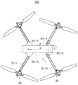
图1是本发明第一实施例的一种可折叠的无人飞行器的立体示意图,所述无人飞行器处于展开状态。FIG. 1 is a schematic perspective view of a foldable unmanned aerial vehicle according to a first embodiment of the present invention, and the unmanned aerial vehicle is in an unfolded state.
图2是图1的无人飞行器的另一视角的示意图。FIG. 2 is a schematic diagram of another perspective of the unmanned aerial vehicle of FIG. 1 .
图3是图2的无人飞行器的部分结构处于折叠状态的示意图。FIG. 3 is a schematic diagram of a partial structure of the unmanned aerial vehicle of FIG. 2 in a folded state.
图4是图2的无人飞行器处于折叠状态的示意图。FIG. 4 is a schematic diagram of the UAV of FIG. 2 in a folded state.
图5是图4的无人飞行器的反向视角的示意图。FIG. 5 is a schematic diagram of a reverse viewing angle of the unmanned aerial vehicle of FIG. 4 .
图6是图1的无人飞行器处于折叠状态的侧表面示意图。FIG. 6 is a schematic side surface view of the UAV of FIG. 1 in a folded state.
图7是图1的无人飞行器处于展开状态的侧表面示意图。FIG. 7 is a schematic side surface view of the unmanned aerial vehicle of FIG. 1 in a deployed state.
图8是本发明第二实施例的一种无人飞行器处于折叠状态的示意图。FIG. 8 is a schematic diagram of an unmanned aerial vehicle in a folded state according to the second embodiment of the present invention.
图9是本发明第三实施例的一种无人飞行器处于折叠状态的示意图。FIG. 9 is a schematic diagram of an unmanned aerial vehicle in a folded state according to a third embodiment of the present invention.
图10是本发明第四实施例的一种无人飞行器处于展开状态的示意图。FIG. 10 is a schematic diagram of an unmanned aerial vehicle in a deployed state according to the fourth embodiment of the present invention.
图11是图10的无人飞行器侧表面示意图。FIG. 11 is a schematic view of a side surface of the UAV of FIG. 10 .
图12是图11的无人飞行器的两部分结构绕转动机构旋转后的示意图。FIG. 12 is a schematic diagram of the two-part structure of the unmanned aerial vehicle of FIG. 11 after being rotated around a rotating mechanism.
图13是图2的无人飞行器的机身的另一种结构示意图。FIG. 13 is another schematic structural diagram of the fuselage of the unmanned aerial vehicle of FIG. 2 .
图14是图13的无人飞行器的机身的另一视角的示意图。FIG. 14 is a schematic diagram of another viewing angle of the fuselage of the unmanned aerial vehicle of FIG. 13 .
图15是本发明实施例的无人飞行器的结构模块图。FIG. 15 is a structural block diagram of an unmanned aerial vehicle according to an embodiment of the present invention.
主要元件符号说明Description of main component symbols
无人飞行器 100、200、300、400
机身 20、21、22、23
头部 20-1Head 20-1
尾部 20-2Tail 20-2
侧表面 20-3、20-4、21-1、22-1Side Surfaces 20-3, 20-4, 21-1, 22-1
顶部 20-5、21-2、22-2、Top 20-5, 21-2, 22-2,
底部 20-6Bottom 20-6
第一安装部 24first mounting
第二安装部 25Second Mounting
收容部 26、261
飞行组件 30
机臂 31
第一机臂 31-1First Arm 31-1
第一转动轴 311-1The first rotating shaft 311-1
第二机臂 31-2Second Arm 31-2
第二转动轴 311-2Second rotating shaft 311-2
脚架 32
动力装置 33
推进单元 331
致动器 332
转动机构 61
第三转动轴 611The
机架 71
动力系统 72
电调 721
电池 722
飞行控制系统 73
飞行控制器 731
传感器模块 732
如下具体实施方式将结合上述附图进一步说明本发明。The following specific embodiments will further illustrate the present invention in conjunction with the above drawings.
具体实施方式Detailed ways
需要说明的是,当组件被称为“固定于”另一个组件,它可以直接在另一个组件上或者也可以存在居中的组件。当一个组件被认为是“连接”另一个组件,它可以是直接连接到另一个组件或者可能同时存在居中组件。本文所使用的术语“垂直的”、“水平的”、“左”、“右”以及类似的表述只是为了说明的目的。It should be noted that when a component is referred to as being "fixed to" another component, it can be directly on the other component or there may also be a centered component. When a component is considered to be "connected" to another component, it may be directly connected to the other component or there may be a co-existence of an intervening component. The terms "vertical," "horizontal," "left," "right," and similar expressions are used herein for illustrative purposes only.
除非另有定义,本文所使用的所有的技术和科学术语与属于本发明的技术领域的技术人员通常理解的含义相同。本文中在本发明的说明书中所使用的术语只是为了描述具体的实施例的目的,不是旨在于限制本发明。本文所使用的术语“及/或”包括一个或多个相关的所列项目的任意的和所有的组合。Unless otherwise defined, all technical and scientific terms used herein have the same meaning as commonly understood by one of ordinary skill in the art to which this invention belongs. The terms used herein in the description of the present invention are for the purpose of describing specific embodiments only, and are not intended to limit the present invention. As used herein, the term "and/or" includes any and all combinations of one or more of the associated listed items.
下面将结合本发明实施例中的附图,对本发明实施例中的技术方案进行清楚、完整地描述,显然,所描述的实施例仅仅是本发明一部分实施例,而不是全部的实施例。基于本发明中的实施例,本领域普通技术人员在没有作出创造性劳动前提下所获得的所有其他实施例,都属于本发明保护的范围。在不冲突的情况下,下述的实施例及实施例中的特征可以相互组合。The technical solutions in the embodiments of the present invention will be clearly and completely described below with reference to the accompanying drawings in the embodiments of the present invention. Obviously, the described embodiments are only a part of the embodiments of the present invention, but not all of the embodiments. Based on the embodiments of the present invention, all other embodiments obtained by those of ordinary skill in the art without creative efforts shall fall within the protection scope of the present invention. The embodiments described below and features in the embodiments may be combined with each other without conflict.
本发明实施例提供一种无人飞行器的机架,包括机身以及机臂。所述机臂可转动地连接于所述机身,使所述机臂能够相对于所述机身选择性地处于折叠状态或者展开状态。其中,在所述折叠状态与所述展开状态时,所述机臂的自由端相较于所述机身的底部的高度以及相较于所述机身的侧表面的距离均不相同。Embodiments of the present invention provide a frame of an unmanned aerial vehicle, including a fuselage and an arm. The machine arm is rotatably connected to the fuselage, so that the machine arm can be selectively folded or unfolded relative to the fuselage. Wherein, in the folded state and the unfolded state, the height of the free end of the arm compared to the bottom of the fuselage and the distance from the side surface of the fuselage are different.
本发明实施例还提供一种无人飞行器,包括上述实施例所述的机架,所述机架包括机身以及机臂;以及承载在所述机臂的自由端的动力装置,所述动力装置用于提供飞行动力。An embodiment of the present invention further provides an unmanned aerial vehicle, including the frame described in the above embodiments, the frame including a fuselage and an arm; and a power device carried on the free end of the arm, the power device Used to provide flight power.
本发明实施例还提供一种无人飞行器,所述无人飞行器包括机身以及用于提供飞行动力的飞行组件。所述飞行组件可活动地连接于所述机身,使所述飞行组件能够相对于所述机身选择性地处于折叠状态或者展开状态。其中,在所述折叠状态与所述展开状态时,所述飞行组件相较于所述机身的底部的高度以及相较于所述机身的侧表面的距离均不相同。Embodiments of the present invention also provide an unmanned aerial vehicle, the unmanned aerial vehicle includes a fuselage and a flight component for providing flight power. The flying assembly is movably connected to the fuselage such that the flying assembly can be selectively folded or unfolded relative to the fuselage. Wherein, in the folded state and the unfolded state, the height of the flying assembly compared to the bottom of the fuselage and the distance from the side surface of the fuselage are different.
本发明实施例还提供一种用于组装成无人飞行器的套件,所述套件包括无人飞行器的机身以及用于提供飞行动力的飞行组件。其中,按照组装操作指示在所述机身上组装所述飞行组件,使得组装后的所述飞行组件可活动地连接于所述机身,并使所述飞行组件能够相对于所述机身选择性地处于折叠状态或者展开状态。其中,在所述折叠状态与所述展开状态时,所述飞行组件相较于所述机身的底部的高度以及相较于所述机身的侧表面的距离均不相同。Embodiments of the present invention also provide a kit for assembling into an unmanned aerial vehicle, the kit including a fuselage of the unmanned aerial vehicle and a flight component for providing flight power. Wherein, the flying assembly is assembled on the fuselage according to the assembly operation instructions, so that the assembled flying assembly can be movably connected to the fuselage, and the flying assembly can be selected relative to the fuselage is either folded or unfolded. Wherein, in the folded state and the unfolded state, the height of the flying assembly compared to the bottom of the fuselage and the distance from the side surface of the fuselage are different.
本发明实施例还提供一种无人飞行器的组装方法,包括:提供无人飞行器的机身,提供用于提供飞行动力的飞行组件,以及在所述机身上组装所述飞行组件,使得组装后的所述飞行组件可活动地连接于所述机身,并使所述飞行组件能够相对于所述机身选择性地处于折叠状态或者展开状态。其中,在所述折叠状态与所述展开状态时,所述飞行组件相较于所述机身的底部的高度以及相较于所述机身的侧表面的距离均不相同。An embodiment of the present invention also provides a method for assembling an unmanned aerial vehicle, including: providing a fuselage of the unmanned aerial vehicle, providing a flying component for providing flight power, and assembling the flying component on the fuselage, so that the assembly The rear flight assembly is movably connected to the fuselage and enables the flight assembly to be selectively folded or unfolded relative to the fuselage. Wherein, in the folded state and the unfolded state, the height of the flying assembly compared to the bottom of the fuselage and the distance from the side surface of the fuselage are different.
本发明实施例还提供一种无人飞行器的操作方法,包括:提供上述各实施例所述的无人飞行器,操作所述无人飞行器,使所述无人飞行器的飞行组件在折叠状态时相较于所述机身具有紧凑的形状,以及在展开状态时相较于所述机身具有展开的形状。An embodiment of the present invention also provides an operation method for an unmanned aerial vehicle, including: providing the unmanned aerial vehicle described in the above-mentioned embodiments, and operating the unmanned aerial vehicle so that the flying components of the unmanned aerial vehicle are in a folded state. It has a compact shape compared to the fuselage, and has an expanded shape compared to the fuselage in a deployed state.
具体地,请参阅图1,是本发明第一实施例的一种可折叠的无人飞行器100的立体示意图。在本实施方式中,所述无人飞行器100为旋翼无人飞行器,其用于搭载照相机、摄像机等拍摄装置(图未示)进行航拍作业。可以理解,所述无人飞行器100还可以用于执行地图测绘、灾情调查和救援、空中监控、输电线路巡检等工作。同样可以理解的是,在其他实施方式中,所述无人飞行器100还可以为固定翼无人飞行器。Specifically, please refer to FIG. 1 , which is a schematic perspective view of a foldable unmanned
在本实施方式中,所述无人飞行器100至少包括机身20以及用于提供飞行动力的飞行组件30。所述机身20的形状可以为各种形状,例如长方体、球体、椭圆体等。In this embodiment, the
如图1所示,用原点O来标示所述无人飞行器100的重心,可根据所述原点O来分别定义出所述无人飞行器100的横滚轴X(沿X轴方向)、俯仰轴Y(沿Y方向)、偏航轴Z(沿Z轴方向)。所述无人飞行器100在飞行过程中可被配置为相较于所述横滚轴X、俯仰轴Y、偏航轴Z中的一个或多个轴旋转。As shown in FIG. 1 , the center of gravity of the
在本实施方式中,所述机身20可包括头部20-1、尾部20-2、侧表面20-3和20-4、顶部20-5、底部20-6(如图5所示)。其中,所述头部20-1可位于所述机身20沿所述横滚轴X方向的一端、所述尾部20-2可位于所述机身20沿所述横滚轴X方向的另一端。所述侧表面20-3和20-4可位于所述机身20沿所述俯仰轴Y方向的两端。所述顶部20-5可位于所述机身20沿所述偏航轴Z方向的一端、所述底部20-6可位于所述机身20沿所述偏航轴Z方向的另一端。In this embodiment, the
进一步地,所述顶部20-5是指所述无人飞行器100处于正常飞行状态时面向天空的一个表面,所述底部20-6是指所述无人飞行器100正常着陆时面向地面的一个表面,所述侧表面20-3、20-4是指连接所述顶部20-5与所述底部20-6的表面。Further, the top 20-5 refers to a surface facing the sky when the
请一并参阅图1-5,在本实施方式中,所述飞行组件30可活动地连接于所述机身20,使所述飞行组件30能够相对于所述机身20选择性地处于折叠状态或者展开状态。具体地,当所述无人飞行器100处于闲置的非飞行状态时,所述飞行组件30能够相对于所述机身20转动,并收拢于所述机身20的周围呈所述折叠状态,使所述飞行组件30所占用的空间较小,从而使所述无人飞行器100在闲置的非飞行状态时的结构比较紧凑,便于收纳及携带。当所述无人飞行器100处于飞行状态时,所述飞行组件30能够相对于所述机身20展开,以便给所述无人飞行器100提供飞行动力。Please refer to FIGS. 1-5 together. In this embodiment, the flying
其中,在所述折叠状态与所述展开状态时,所述飞行组件30相较于所述机身20的侧表面20-3或20-4的距离不相同。在本实施方式中,所述飞行组件在所述折叠状态时相较于所述机身的侧表面的距离,小于在所述展开状态时相较于所述机身的侧表面的距离。Wherein, in the folded state and the unfolded state, the distance between the flying
在本实施方式中,所述飞行组件30包括机臂31,所述机臂31可转动地连接于所述机身20的侧表面20-3、20-4,使所述机臂31能够相对于所述机身20选择性地处于折叠状态或者展开状态。其中,所述机臂31的数量可以为多个,例如,三个、四个、五个、六个或六个以上。在本实施方式中,所述机臂31的数量为四个。In this embodiment, the flying
在本实施方式中,在所述折叠状态与所述展开状态时,所述机臂31的自由端相较于所述机身20的侧表面20-3或20-4的距离不相同。In this embodiment, in the folded state and the unfolded state, the distance between the free end of the
具体地,在本实施方式中,所述机臂31能够相对于所述机身20选择性地保持于预定的折叠位置(如图4-5所示的位置)以及预定的展开位置(如图1-2所示的位置),且能够在所述折叠位置与所述展开位置之间转动。其中,当所述机臂31位于所述折叠位置时,所述机臂31的自由端紧贴所述机身20,当所述机臂31位于所述展开位置时,所述机臂31的自由端远离所述机身20。也就是说,所述机臂31的自由端在所述折叠状态时相较于所述机身20的侧表面20-3或20-4的距离,小于在所述展开状态时相较于所述机身20的侧表面20-3或20-4的距离。Specifically, in this embodiment, the
可选地,所述机身20上还可包括转动限位结构(图未示),所述转动限位结构用于与所述机臂31连接,并限定所述机臂31的转动角度。其中,所述转动限位结构可为挡块或弹性件,例如可提供预紧力及/或回弹力的弹片、弹簧等。Optionally, the
可选地,所述机身20上还可包括锁定结构(图未示),所述锁定结构用于与所述机臂31连接,并在所述展开状态下使所述机臂31能够保持于所述预定的展开位置,以及在所述折叠状态下使所述机臂31能够保持于所述预定的折叠位置。其中,所述锁定结构可为卡扣、卡钩等。Optionally, the
可选地,所述机身20上还可包括弹性件(图未示),所述弹性件用于与所述机臂31连接,并在所述机臂31相对于所述机身20折叠到第一预定位置时驱使所述机臂31自动缩回到所述预定的折叠位置,及/或,在所述机臂31相对于所述机身20展开到第二预定位置时驱使所述机臂31自动展开到所述预定的展开位置。Optionally, the
请再次参阅图1,在本实施方式中,所述飞行组件30还包括连接于所述机臂31的自由端的脚架32,所述脚架32用于在所述无人飞行器100的着陆过程中保护所述机身20不受到撞击以及在所述无人飞行器100着陆于一支撑面(图未示),例如地面时支撑所述机身20。Please refer to FIG. 1 again, in this embodiment, the flying
在本实施方式中,所述飞行组件30还包括连接于所述机臂31的自由端的、用于提供飞行动力的动力装置33。其中,所述动力装置33可以包括推进单元331以及致动器332。其中,所述推进单元331通过所述致动器332连接至相应机臂31的自由端。所述推进单元331可以使得所述无人飞行器100移动,并可以提供所述无人飞行器100的上升动力,以使所述无人飞行器100改变高度。其中,所述推进单元331可以是用于旋转以提供上升动力给所述无人飞行器100的旋翼。在本实施方式中,所述推进单元331采用螺旋桨,且包括至少两片桨叶,所述螺旋桨的桨叶能够折叠在一起,从而可缩短所述桨叶的收容空间,从而有利于在折叠状态下减小所述无人飞行器100的机身20在长度方向上的体积。In this embodiment, the flying
所述致动器332可以是电机,例如,交流电机或直流电机。所述致动器332用于响应来自所述无人飞行器100的飞行控制器的指令信号,以带动所述推进单元331转动,从而提供所述无人飞行器100的升力。其中,所述指令信号包括对所述致动器332的输出。The
在本实施方式中,由于所述脚架32以及所述动力装置33均连接于所述机臂31的自由端,因此,在所述折叠状态与所述展开状态时,所述脚架32以及所述动力装置33相较于所述机身20的侧表面20-3或20-4的距离也均不相同。In this embodiment, since both the
具体地,在本实施方式中,所述脚架32以及所述动力装置33在所述折叠状态时相较于所述机身20的侧表面20-3或20-4的距离,均小于在所述展开状态时相较于所述机身20的侧表面20-3或20-4的距离。Specifically, in this embodiment, the distance between the
在本实施方式中,连接于同一所述机臂31的所述脚架32与所述动力装置33分别位于所述机臂31的自由端的相对两侧,且所述脚架32在所述机臂31位于所述展开位置时凸出于所述机身20的底部20-6。In this embodiment, the
请一并参阅图6-7,在本实施方式中,在所述折叠状态与所述展开状态时,所述飞行组件30相较于所述机身20的底部20-6的高度也不相同。Please refer to FIGS. 6-7 together. In this embodiment, in the folded state and the unfolded state, the height of the flying
具体地,在所述折叠状态与所述展开状态时,所述脚架32以及所述动力装置33相较于所述机身20的底部20-6的高度均不相同。Specifically, in the folded state and the unfolded state, the heights of the
在本实施方式中,所述机臂31包括第一机臂31-1,其中,在所述折叠状态与所述展开状态时,所述第一机臂31-1的自由端相较于所述机身20的底部20-6的高度不相同。In this embodiment, the
具体地,所述第一机臂31-1可相对于所述机身20的侧表面20-3或20-4绕第一转动轴311-1转动。其中,所述第一转动轴311-1相对于所述无人飞行器100的偏航轴Z呈第一预定倾斜角度α,且所述第一转动轴311-1大致平行于所述无人飞行器100的偏航轴Z与横滚轴X所确定的平面。Specifically, the first arm 31-1 can rotate about the first rotation axis 311-1 relative to the side surface 20-3 or 20-4 of the
在本实施方式中,由于所述第一转动轴311-1的倾斜设置,且所述第一机臂31-1绕所述第一转动轴311-1在同一平面上转动,使得所述第一机臂31-1自所述折叠状态转动以进入所述展开状态的同时,所述第一机臂31-1的自由端相较于所述机身20的底部20-6的高度降低。即,所述第一机臂31-1的自由端在所述折叠状态时相较于所述机身20的底部20-6的高度,大于在所述展开状态时相较于所述机身20的底部20-6的高度。In this embodiment, due to the inclined arrangement of the first rotating shaft 311-1, and the first arm 31-1 rotates on the same plane around the first rotating shaft 311-1, the first arm 31-1 rotates on the same plane. When a machine arm 31 - 1 is rotated from the folded state to enter the unfolded state, the height of the free end of the first machine arm 31 - 1 is lower than that of the bottom 20 - 6 of the
在本实施方式中,所述第一预定倾斜角度α为2-3度。可以理解的是,所述第一预定倾斜角度α可以根据实际情况调整,从而调整所述第一机臂31-1的自由端相对于所述机身20的底部20-6的高度幅度。In this embodiment, the first predetermined inclination angle α is 2-3 degrees. It can be understood that the first predetermined inclination angle α can be adjusted according to actual conditions, so as to adjust the height of the free end of the first arm 31 - 1 relative to the bottom 20 - 6 of the
在本实施方式中,连接于所述第一机臂31-1的所述脚架32以及所述动力装置33的朝向在所述第一机臂31-1的转动过程中均保持不变。在本实施方式中,连接于所述第一机臂31-1的所述脚架322台终朝向所述机身20的底部20-6,连接于所述第一机臂31-1的所述动力装置33始终朝向所述机身20的顶部20-5。In this embodiment, the orientations of the
在本实施方式中,由于所述第一转动轴311-1的倾斜设置,使得连接于所述第一机臂31-1的所述脚架32的自由端在所述折叠状态时凸出于所述机身20的底部20-6的长度为H1,在所述展开状态时凸出于所述机身20的底部20-6的长度为H2,其中,H1<H2。因此,连接于所述第一机臂31-1的所述脚架32的自由端在所述折叠状态时相较于所述机身20的底部20-6的高度(-H1),大于在所述展开状态时相较于所述机身20的底部20-6的高度(-H2)。In this embodiment, due to the inclined arrangement of the first rotating shaft 311-1, the free end of the
在本实施方式中,所述脚架32在所述第一机臂31-1位于所述展开位置时凸出于所述机身20的底部20-6,即所述长度H2为正数。所述脚架32在所述第一机臂31-1位于所述折叠位置时也凸出于所述机身20的底部20-6,即所述长度H1也为正数。In this embodiment, the
可以理解的是,在其他实施方式中,可根据实际情况调整所述第一机臂的转动轴的第一预定倾斜角度,或调整所述脚架32的长度,使得所述脚架32在所述第一机臂31-1位于所述折叠位置时不凸出于所述机身20的底部20-6,即所述长度H1为零或为负数。It can be understood that, in other embodiments, the first predetermined inclination angle of the rotation axis of the first arm can be adjusted according to the actual situation, or the length of the
本实施例的所述无人飞行器100通过倾斜设置所述第一机臂31-1的第一转动轴311-1,并通过所述第一机臂31-1带动所连接的所述脚架32转动以调整所连接的所述脚架32的高度,使连接于所述第一机臂31-1的脚架32在所述折叠状态与所述展开状态下产生高度差,从而可改变所述脚架32凸出于所述机身20的底部20-6的长度。In the
由于在所述折叠状态时所述第一机臂31-1上的所述脚架32凸出于所述机身20的底部20-6的长度减小或消失,从而有利于在所述折叠状态下减小所述无人飞行器100的机身20在高度方向上的体积,使折叠后的所述无人飞行器100的结构更加紧凑。而且不需要在所述第一机臂31-1的自由端增加转动机构以折叠相应的脚架32,结构较简单。Since the length of the
在本实施方式中,连接于所述第一机臂31-1的所述动力装置33在所述折叠状态时相较于所述机身20的底部20-6的高度,大于在所述展开状态时相较于所述机身20的底部20-6的高度。如图6所示,在本实施方式中,所述第一机臂31-1在所述折叠状态时将所连接的所述动力装置33的推进单元331搁置于所述机身20的顶部20-5。In this embodiment, the height of the
在本实施方式中,所述机臂31还包括第二机臂31-2,如图2所示,所述第二机臂31-2可相对于所述机身20的侧表面20-3或20-4绕第二转动轴311-2转动。其中,所述第二转动轴311-2相对于所述无人飞行器100的横滚轴X呈第二预定倾斜角度β,且所述第二转动轴311-2大致垂直于所述无人飞行器100的偏航轴Z,使得所述第二机臂31-2绕所述第二转动轴311-2沿一圆锥面旋转。In this embodiment, the
在本实施方式中,由于所述第二机臂31-2沿圆锥面旋转,使得所述第二机臂31-2自所述折叠状态转动以进入所述展开状态的同时,所述第二机臂31-2相较于所述机身20翻转180度,使所述第二机臂31-2朝向所述机身20的顶部20-5的表面转为朝向所述机身20的底部20-6。In this embodiment, since the second arm 31-2 rotates along the conical surface, when the second arm 31-2 rotates from the folded state to enter the unfolded state, the second arm 31-2 rotates along the conical surface. The arm 31-2 is turned 180 degrees compared to the
在本实施方式中,连接于所述第二机臂31-2的所述脚架32的朝向在所述第二机臂31-2的转动过程中也跟随所述第二机臂31-2翻转180度,即连接于所述第二机臂31-2的所述脚架32在所述折叠状态时朝向所述机身20的顶部20-5,在所述展开状态时朝向所述机身20的底部20-6。因此,连接于所述第二机臂31-2的所述脚架32的自由端在所述折叠状态时相较于所述机身20的底部20-6的高度,大于在所述展开状态时相较于所述机身20的底部20-6的高度。In this embodiment, the orientation of the
本实施例的所述无人飞行器100通过所述第二机臂31-2沿圆锥面旋转,并通过所述第二机臂31-2带动所连接的所述脚架32翻转以调整所连接的所述脚架32的高度,使连接于所述第二机臂31-2的脚架32在所述展开状态时凸出于所述机身20的底部20-6,在所述折叠状态时朝向所述机身20的顶部20-5,且不凸出于所述机身20的顶部20-5。The unmanned
由于在所述折叠状态时所述第二机臂31-2上的所述脚架32朝向所述机身20的顶部20-5,且不凸出于所述机身20的顶部20-5,从而有利于在所述折叠状态下减小所述无人飞行器100的机身20在高度方向上的体积,使折叠后的所述无人飞行器100的结构更加紧凑。而且不需要在所述第二机臂31-2的自由端增加转动机构以折叠相应的脚架32,结构较简单。In the folded state, the
在本实施方式中,连接于所述第二机臂31-2的所述动力装置33的朝向在所述第二机臂31-2的转动过程中也跟随所述第二机臂31-2翻转180度,即连接于所述第二机臂31-2的所述动力装置33在所述折叠状态时朝向所述机身20的顶部20-5,在所述展开状态时朝向所述机身20的底部20-6。因此,在本实施方式中,连接于所述第二机臂31-2的所述动力装置33在所述折叠状态时相较于所述机身20的底部20-6的高度,小于在所述展开状态时相较于所述机身20的底部20-6的高度。如图6所示,在本实施方式中,所述第二机臂31-2在所述折叠状态时将所连接的所述动力装置33的推进单元331搁置于所述机身20的底部20-6。In this embodiment, the orientation of the
在本发明实施例中,所述机臂31在所述折叠状态时将相应的推进单元331搁置于所述机身23的顶部20-5或底部20-6。在其他实施方式中,所述机臂31的自由端附近可设有转动机构(图未示),所述转动机构用于在所述折叠位置时转动所述机臂31的自由端,使所述推进单元331搁置于所述机身20的侧表面20-3或20-4。In the embodiment of the present invention, when the
在本发明实施例中,所述无人飞行器100通过所述机臂31相对所述机身20旋转,以实现在所述折叠状态时缩短所连接的所述脚架32凸出于所述机身20的长度。在其他实施方式中,所述脚架32能够相对于所连接的机臂31折叠至贴附于所连接的机臂31上,以便在所述折叠状态下减小所述无人飞行器100的体积,使所述无人飞行器100的结构更加紧凑。In the embodiment of the present invention, the unmanned
在本发明实施例中,所述无人飞行器100包括至少一对所述第一机臂31-1以及至少一对所述第二机臂31-2。在本实施方式中,每一对所述第一机臂31-1相对连接于所述机身20的两个侧表面20-5和20-6,每一对所述第二机臂31-2相对连接于所述机身20的两个侧表面20-5和20-6。所述第一机臂31-1以及所述第二机臂31-2分别连接于所述机身20的同一侧表面的相对两端,且所述第一机臂31-1与所述第二机臂31-2上下错位,使所述第一机臂31-1与所述第二机臂31-2在所述折叠状态时能够相互扣合在一起。In this embodiment of the present invention, the
可选的,在其他实施方式中,所述无人飞行器100可包括多个所述第一机臂31-1,例如,所述第一机臂31-1的数量可为四个、六个、八个或其他数量。例如图8所示,所述无人飞行器200的多个所述第一机臂31-1分别连接于所述机身21的不同的侧表面21-1。所述第一机臂31-1在所述折叠状态时将所连接的所述动力装置33的推进单元331搁置于所述机身20的顶部21-2。Optionally, in other embodiments, the
或者,例如图9所示,所述无人飞行器300的多个所述第一机臂31-1分别两两相对连接于所述机身22的同一侧表面22-1的相对两端,且两两相对连接于所述机身22的相对两侧表面22-1上。所述第一机臂31-1在所述折叠状态时将所连接的所述动力装置33的推进单元331搁置于所述机身22的顶部22-2。进一步地,所述机身22的长度至少不小于两个所述第一机臂31-1的长度之和,从而可将两个所述第一机臂31-1所连接的推进单元331并排搁置于所述机身22的顶部22-2。Alternatively, for example, as shown in FIG. 9 , the plurality of first arms 31 - 1 of the
可以理解的是,在其他实施方式中,所述无人飞行器100也可包括多个所述第二机臂31-2,例如,多个所述第二机臂31-2可分别连接于所述机身20的不同的侧表面,或者,两两相对连接于所述机身20的同一侧表面的相对两端,或者,两两相对连接于所述机身20的相对两侧表面上。It can be understood that, in other embodiments, the
可选的,在其他实施方式中,例如图10-11所示,所述无人飞行器400还包括设置于所述机身23上的转动机构61,所述转动机构61将所述机身23分为两部分,且使所述机身23的其中一部分能够相对于另一部分绕所述转动机构61的第三转动轴611旋转180度。其中,所述第三转动轴611大致平行于所述无人飞行器400的横滚轴X。Optionally, in other embodiments, such as shown in FIGS. 10-11 , the
如图12所示,当所述机身23的其中一部分相对于另一部分绕所述转动机构61的第三转动轴611旋转180度后,使得连接于所述机身23的其中一部分的飞行组件30相对连接于所述机身23的另一部分的飞行组件30旋转180度。即,连接于同一侧表面20-3或20-4的两个所述机臂31上的飞行组件30的朝向相反。其中,连接于所述机身23的两部分的所述机臂31,例如第一机臂31-1在所述折叠状态时分别将相应的推进单元331搁置于所述机身23的顶部23-2和底部23-1。可以理解的是,所述机臂31也可以是所述第二机臂31-2。As shown in FIG. 12 , when one part of the
其中,所述机身23的长度可大致等于一个所述机臂31的长度,以缩短机身23的长度,从而有利于在折叠状态下减小所述无人飞行器400的机身23在长度方向上的体积。The length of the
请再次参阅图1,在本发明实施例中,所述机身20上还设有第一安装部24,所述第一机臂31-1安装于所述第一安装部24上。其中,所述第一安装部24凸设于所述机身20上。在其他实施方式中,所述机身20上还可设有导向槽(图未示),所述第一机臂31-1安装于所述导向槽中,所述第一机臂31-1位于所述折叠位置时收容于所述导向槽中。Referring to FIG. 1 again, in the embodiment of the present invention, the
在本发明实施例中,所述机身20上还设有第二安装部25,所述第二机臂31-2安装于所述第二安装部25上。其中,所述第二安装部25凸设于所述机身20上。In the embodiment of the present invention, the
请一并参阅图1、6、7,在本发明实施例中,所述机身20上还设有收容部26,所述收容部26与位于预定的折叠位置时的所述致动器332相对,用于收容所述致动器332的部分结构。其中,所述收容部26设于所述机身20的顶部20-5、侧表面20-3和20-4、以及尾部20-2(或头部20-1)的交界处,及/或设于所述机身20的底部20-6、侧表面20-3和20-4以及头部20-1(或尾部20-2)的交界处。Please refer to FIGS. 1 , 6 and 7 together. In the embodiment of the present invention, the
在其他实施方式中,如图13-14所示,收容部261可设于所述机身20的顶部20-5与侧表面20-3或20-4的交界处,及/或,设于所述机身20的底部20-6与侧表面20-3或20-4的交界处。其中,所述收容部261与相应的致动器332的部分结构的形状相适配。In other embodiments, as shown in FIGS. 13-14 , the receiving
可选的,所述无人飞行器100还可包括通信天线(图未示),所述脚架32还用于给所述通信天线提供附设空间。在本实施方式中,所述脚架32相对于所连接的机臂31的长度方向呈非正交角度,从而在不增加所述脚架32凸出于所述机身20的长度的情况下增大所述通信天线与所述机身20之间的距离,使得所述通信天线能够尽可能远离所述机身20内的电子元件产生的电磁干扰,以利于改善所述天线传输信号的性能。Optionally, the unmanned
所述机身20可以为一壳体,其内部可包含有所述无人飞行器100的其他元件,例如飞行控制器、惯性测量单元(Inertial measurement unit,IMU)、电调、电池等。The
其中,所述飞行控制器用于控制所述无人飞行器100的飞行状态,包括飞行速度、飞行姿态等。所述惯性测量单元用于检测所述无人飞行器100的姿态。所述电调设置在所述机身20内,并与所述飞行控制器电性连接。所述电调在所述飞行控制器的控制下,能够调节所述动力装置33的转动速度及转动方向。其中,所述电调可以为多个,多个所述电调中的一个或多个分别与所述动力装置33相连接,并用于调节所述动力装置的转动速度及转动方向,以调节所述无人飞行器100的飞行速度和飞行姿态。所述电池用于给所述无人飞行器100提供工作电源。The flight controller is used to control the flight state of the
如图15所示,在本实施方式中,也可以理解为所述无人飞行器100包括机架71、动力系统72、飞行控制系统73。其中,所述动力系统以及所述飞行控制系统设置于所述机架41上或设置于所述机架41内。所述机架71至少包括所述机身20(或21或22或23)、所述机臂31以及所述脚架32。所述机身20(或21或22或23)也可称为中心架。在本实施方式中,所述机臂31与所述机身20(或21或22或23)连接,所述脚架32与所述机臂31的自由端连接。在其他实施方式中,所述机臂412和所述脚架413分别与所述机身411连接。As shown in FIG. 15 , in this embodiment, it can also be understood that the
所述动力系统72至少包括所述动力装置33、所述电调721、以及所述电池722。The
所述飞行控制系统73至少包括飞行控制器731以及多个传感器模块732。其中,所述传感器模块732是能够感测到被测量的信息,并将所感测的信息按一定规律变换成为电信号或其他所需形式的信息输出的元器件。所述传感器模块732可包括但不限于,所述惯性测量单元、指南针、GPS传感器、距离传感器等。The
本发明实施例中的无人飞行器能够在折叠状态改变机臂或飞行组件相较于机身的底部的高度以及相较于所述机身的侧表面的距离,从而有利于在所述折叠状态下减小所述机身的体积,使折叠后的所述无人飞行器的结构更加紧凑,以便于收纳以及携带。The unmanned aerial vehicle in the embodiment of the present invention can change the height of the arms or the flying components relative to the bottom of the fuselage and the distance from the side surface of the fuselage in the folded state, so as to facilitate the folded state The volume of the fuselage is reduced, so that the structure of the folded unmanned aerial vehicle is more compact, which is convenient for storage and carrying.
基于上述无人飞行器,本发明实施例还提供一种套件,用于组装成上述各实施例的无人飞行器。具体地,所述套件包括无人飞行器的机身以及用于提供飞行动力的飞行组件。其中,按照组装操作指示在所述机身上组装所述飞行组件,使得组装后的所述飞行组件可活动地连接于所述机身,并使所述飞行组件能够相对于所述机身选择性地处于折叠状态或者展开状态。其中,在所述折叠状态与所述展开状态时,所述飞行组件相较于所述机身的底部的高度以及相较于所述机身的侧表面的距离均不相同。Based on the above-mentioned unmanned aerial vehicle, an embodiment of the present invention further provides a kit for assembling the unmanned aerial vehicle of the above-mentioned embodiments. Specifically, the kit includes a fuselage of an unmanned aerial vehicle and a flight assembly for providing flight power. Wherein, the flying assembly is assembled on the fuselage according to the assembly operation instructions, so that the assembled flying assembly can be movably connected to the fuselage, and the flying assembly can be selected relative to the fuselage is either folded or unfolded. Wherein, in the folded state and the unfolded state, the height of the flying assembly compared to the bottom of the fuselage and the distance from the side surface of the fuselage are different.
基于上述无人飞行器,本发明实施例还提供一种无人飞行器的组装方法,用于组装成上述各实施例的无人飞行器。具体地,所述组装方法包括:提供无人飞行器的机身,提供用于提供飞行动力的飞行组件,以及在所述机身上组装所述飞行组件,使得组装后的所述飞行组件可活动地连接于所述机身,并使所述飞行组件能够相对于所述机身选择性地处于折叠状态或者展开状态。其中,在所述折叠状态与所述展开状态时,所述飞行组件相较于所述机身的底部的高度以及相较于所述机身的侧表面的距离均不相同。Based on the above-mentioned unmanned aerial vehicle, an embodiment of the present invention further provides an assembly method of an unmanned aerial vehicle, which is used to assemble the unmanned aerial vehicle of the above-mentioned embodiments. Specifically, the assembling method includes: providing a fuselage of an unmanned aerial vehicle, providing a flying component for providing flight power, and assembling the flying component on the fuselage, so that the assembled flying component is movable is groundably connected to the fuselage and enables the flight assembly to be selectively folded or unfolded relative to the fuselage. Wherein, in the folded state and the unfolded state, the height of the flying assembly compared to the bottom of the fuselage and the distance from the side surface of the fuselage are different.
基于上述无人飞行器,本发明实施例还提供一种无人飞行器的操作方法,用于操作上述各实施例的无人飞行器。具体地,所述操作方法包括:提供上述各实施例所述的无人飞行器,操作所述无人飞行器,使所述无人飞行器的飞行组件在折叠状态时相较于所述机身具有紧凑的形状,以及在展开状态时相较于所述机身具有展开的形状。Based on the above-mentioned unmanned aerial vehicle, an embodiment of the present invention further provides an operation method of an unmanned aerial vehicle, which is used to operate the unmanned aerial vehicle of the above-mentioned embodiments. Specifically, the operation method includes: providing the unmanned aerial vehicle described in the above embodiments, and operating the unmanned aerial vehicle so that the flying assembly of the unmanned aerial vehicle has a compact size compared to the fuselage in a folded state , and has an expanded shape compared to the fuselage in the expanded state.
最后应说明的是,以上实施例仅用以说明本发明的技术方案而非限制,尽管参照较佳实施例对本发明进行了详细说明,本领域的普通技术人员应当理解,可以对本发明的技术方案进行修改或等同替换,而不脱离本发明技术方案的精神和范围。Finally, it should be noted that the above embodiments are only used to illustrate the technical solutions of the present invention and not to limit them. Although the present invention has been described in detail with reference to the preferred embodiments, those of ordinary skill in the art should understand that the technical solutions of the present invention can be Modifications or equivalent substitutions can be made without departing from the spirit and scope of the technical solutions of the present invention.
本专利文件披露的内容包含受版权保护的材料。该版权为版权所有人所有。版权所有人不反对任何人复制专利与商标局的官方记录和档案中所存在的该专利文件或者该专利披露。The disclosure of this patent document contains material that is subject to copyright protection. This copyright belongs to the copyright owner. The copyright owner has no objection to the reproduction by anyone of the patent document or the patent disclosure as it exists in the official records and archives of the Patent and Trademark Office.
Claims (124)
Priority Applications (1)
| Application Number | Priority Date | Filing Date | Title |
|---|---|---|---|
| CN202111203485.0A CN113911326B (en) | 2016-02-22 | 2016-04-01 | Unmanned aerial vehicles |
Applications Claiming Priority (3)
| Application Number | Priority Date | Filing Date | Title |
|---|---|---|---|
| PCT/CN2016/074302 WO2017143501A1 (en) | 2016-02-22 | 2016-02-22 | Foldable multi-rotor aerial vehicle |
| CNPCT/CN2016/074302 | 2016-02-22 | ||
| PCT/CN2016/078403 WO2017143644A1 (en) | 2016-02-22 | 2016-04-01 | Unmanned aerial vehicle and frame thereof, kit, assembly method, and operation method |
Related Child Applications (1)
| Application Number | Title | Priority Date | Filing Date |
|---|---|---|---|
| CN202111203485.0A Division CN113911326B (en) | 2016-02-22 | 2016-04-01 | Unmanned aerial vehicles |
Publications (2)
| Publication Number | Publication Date |
|---|---|
| CN108698685A CN108698685A (en) | 2018-10-23 |
| CN108698685B true CN108698685B (en) | 2021-11-02 |
Family
ID=56812576
Family Applications (17)
| Application Number | Title | Priority Date | Filing Date |
|---|---|---|---|
| CN201680082424.4A Active CN108698682B (en) | 2016-02-22 | 2016-04-01 | Unmanned aerial vehicle, frame, kit, assembly method and operation method thereof |
| CN201620265519.7U Expired - Fee Related CN205554572U (en) | 2016-02-22 | 2016-04-01 | Unmanned vehicles and frame thereof |
| CN201680082409.XA Active CN108698685B (en) | 2016-02-22 | 2016-04-01 | Unmanned aerial vehicle and its frame, kit, assembly method, and operation method |
| CN201910013985.4A Expired - Fee Related CN109502006B (en) | 2016-02-22 | 2016-04-01 | Frame of unmanned aerial vehicle, unmanned aerial vehicle and method of using the same |
| CN202111203485.0A Active CN113911326B (en) | 2016-02-22 | 2016-04-01 | Unmanned aerial vehicles |
| CN202210001056.3A Active CN114212242B (en) | 2016-02-22 | 2016-04-01 | Unmanned aerial vehicles |
| CN201620265516.3U Expired - Fee Related CN205707291U (en) | 2016-02-22 | 2016-04-01 | Racks for unmanned aerial vehicles and unmanned aerial vehicles |
| CN202110095791.0A Active CN112744348B (en) | 2016-02-22 | 2016-04-01 | Airframe for unmanned aerial vehicle, unmanned aerial vehicle and method of use |
| CN201620265517.8U Expired - Fee Related CN205554560U (en) | 2016-02-22 | 2016-04-01 | Unmanned vehicles and frame thereof |
| CN201620265520.XU Expired - Fee Related CN205554584U (en) | 2016-02-22 | 2016-04-01 | Unmanned vehicles and frame thereof |
| CN201620265522.9U Expired - Fee Related CN205554561U (en) | 2016-02-22 | 2016-04-01 | Unmanned vehicles and frame thereof |
| CN201620265512.5U Expired - Fee Related CN205707290U (en) | 2016-02-22 | 2016-04-01 | Racks for unmanned aerial vehicles and unmanned aerial vehicles |
| CN201680004362.5A Expired - Fee Related CN107614374B (en) | 2016-02-22 | 2016-04-01 | Frame of unmanned aerial vehicle, unmanned aerial vehicle and method of using the same |
| CN201620377767.0U Expired - Lifetime CN205675222U (en) | 2016-02-22 | 2016-04-29 | Rack and UAV using the rack |
| CN202110403285.3A Pending CN112937836A (en) | 2016-02-22 | 2016-04-29 | drone using rack |
| CN201620377764.7U Expired - Fee Related CN205675221U (en) | 2016-02-22 | 2016-04-29 | Rack and UAV using the rack |
| CN201680004385.6A Active CN107454882B (en) | 2016-02-22 | 2016-04-29 | Frame and use unmanned aerial vehicle of this frame |
Family Applications Before (2)
| Application Number | Title | Priority Date | Filing Date |
|---|---|---|---|
| CN201680082424.4A Active CN108698682B (en) | 2016-02-22 | 2016-04-01 | Unmanned aerial vehicle, frame, kit, assembly method and operation method thereof |
| CN201620265519.7U Expired - Fee Related CN205554572U (en) | 2016-02-22 | 2016-04-01 | Unmanned vehicles and frame thereof |
Family Applications After (14)
| Application Number | Title | Priority Date | Filing Date |
|---|---|---|---|
| CN201910013985.4A Expired - Fee Related CN109502006B (en) | 2016-02-22 | 2016-04-01 | Frame of unmanned aerial vehicle, unmanned aerial vehicle and method of using the same |
| CN202111203485.0A Active CN113911326B (en) | 2016-02-22 | 2016-04-01 | Unmanned aerial vehicles |
| CN202210001056.3A Active CN114212242B (en) | 2016-02-22 | 2016-04-01 | Unmanned aerial vehicles |
| CN201620265516.3U Expired - Fee Related CN205707291U (en) | 2016-02-22 | 2016-04-01 | Racks for unmanned aerial vehicles and unmanned aerial vehicles |
| CN202110095791.0A Active CN112744348B (en) | 2016-02-22 | 2016-04-01 | Airframe for unmanned aerial vehicle, unmanned aerial vehicle and method of use |
| CN201620265517.8U Expired - Fee Related CN205554560U (en) | 2016-02-22 | 2016-04-01 | Unmanned vehicles and frame thereof |
| CN201620265520.XU Expired - Fee Related CN205554584U (en) | 2016-02-22 | 2016-04-01 | Unmanned vehicles and frame thereof |
| CN201620265522.9U Expired - Fee Related CN205554561U (en) | 2016-02-22 | 2016-04-01 | Unmanned vehicles and frame thereof |
| CN201620265512.5U Expired - Fee Related CN205707290U (en) | 2016-02-22 | 2016-04-01 | Racks for unmanned aerial vehicles and unmanned aerial vehicles |
| CN201680004362.5A Expired - Fee Related CN107614374B (en) | 2016-02-22 | 2016-04-01 | Frame of unmanned aerial vehicle, unmanned aerial vehicle and method of using the same |
| CN201620377767.0U Expired - Lifetime CN205675222U (en) | 2016-02-22 | 2016-04-29 | Rack and UAV using the rack |
| CN202110403285.3A Pending CN112937836A (en) | 2016-02-22 | 2016-04-29 | drone using rack |
| CN201620377764.7U Expired - Fee Related CN205675221U (en) | 2016-02-22 | 2016-04-29 | Rack and UAV using the rack |
| CN201680004385.6A Active CN107454882B (en) | 2016-02-22 | 2016-04-29 | Frame and use unmanned aerial vehicle of this frame |
Country Status (4)
| Country | Link |
|---|---|
| US (3) | US10625855B2 (en) |
| EP (2) | EP3419894B1 (en) |
| CN (17) | CN108698682B (en) |
| WO (5) | WO2017143501A1 (en) |
Families Citing this family (158)
| Publication number | Priority date | Publication date | Assignee | Title |
|---|---|---|---|---|
| US12221237B2 (en) * | 2015-04-21 | 2025-02-11 | Gopro, Inc. | Unmanned aerial vehicle with rotating and overlapping rotor arms |
| CN112722300A (en) | 2015-04-21 | 2021-04-30 | 高途乐公司 | Aerial capture platform |
| US11292598B2 (en) * | 2015-12-08 | 2022-04-05 | Mark Bradford FOLEY | Handheld aircraft with adjustable components |
| US10494094B2 (en) * | 2015-12-08 | 2019-12-03 | Mark Bradford FOLEY | Handheld aircraft with adjustable components |
| EP3419894B1 (en) | 2016-02-22 | 2021-11-10 | SZ DJI Technology Co., Ltd. | Foldable multi-rotor aerial vehicle |
| FR3048185B1 (en) * | 2016-02-25 | 2018-03-23 | Parrot Drones | DRONE WITH FOLDING LINK ARM. |
| US11117660B2 (en) * | 2016-04-19 | 2021-09-14 | Advanced Aircraft Company | Unmanned aerial vehicle including transversely extending support booms |
| US20170313400A1 (en) * | 2016-04-27 | 2017-11-02 | Atlas Dynamic Limited | Collapsible unmanned aerial vehicle (uav) |
| CN109070989B (en) | 2016-05-28 | 2022-05-17 | 深圳市大疆创新科技有限公司 | foldable unmanned aerial vehicle |
| US10737765B2 (en) | 2016-07-01 | 2020-08-11 | Textron Innovations Inc. | Aircraft having single-axis gimbal mounted propulsion systems |
| US10633087B2 (en) * | 2016-07-01 | 2020-04-28 | Textron Innovations Inc. | Aircraft having hover stability in inclined flight attitudes |
| US11608173B2 (en) | 2016-07-01 | 2023-03-21 | Textron Innovations Inc. | Aerial delivery systems using unmanned aircraft |
| US10315761B2 (en) | 2016-07-01 | 2019-06-11 | Bell Helicopter Textron Inc. | Aircraft propulsion assembly |
| US10625853B2 (en) * | 2016-07-01 | 2020-04-21 | Textron Innovations Inc. | Automated configuration of mission specific aircraft |
| US10633088B2 (en) | 2016-07-01 | 2020-04-28 | Textron Innovations Inc. | Aerial imaging aircraft having attitude stability during translation |
| US10604249B2 (en) * | 2016-07-01 | 2020-03-31 | Textron Innovations Inc. | Man portable aircraft system for rapid in-situ assembly |
| US10597164B2 (en) * | 2016-07-01 | 2020-03-24 | Textron Innovations Inc. | Aircraft having redundant directional control |
| CN106347623B (en) * | 2016-09-20 | 2018-11-13 | 深圳市高巨创新科技开发有限公司 | A kind of aircraft shaft and aircraft |
| US10752334B2 (en) * | 2016-09-30 | 2020-08-25 | Edward Chow | Collapsible and rapidly-deployable unmanned aerial vehicle |
| WO2018151777A1 (en) * | 2016-11-02 | 2018-08-23 | Joby Aviation, Inc. | Vtol aircraft using rotors to simulate rigid wing dynamics |
| CN107010197B (en) * | 2016-11-22 | 2023-09-12 | 中国人民解放军空军工程大学 | A static propeller specific direction generating and fixing mechanism |
| US10479499B2 (en) * | 2016-11-30 | 2019-11-19 | The Boeing Company | Self-contained aerial cargo vehicle |
| CN106527464A (en) * | 2016-12-06 | 2017-03-22 | 深圳市元征科技股份有限公司 | Unmanned aerial vehicle (UAV) attitude maintaining method and device |
| KR102306463B1 (en) * | 2016-12-07 | 2021-09-28 | 에스지 디제이아이 테크놀러지 코., 엘티디 | Multi-rotor unmanned aerial vehicle |
| CN108609165A (en) * | 2016-12-09 | 2018-10-02 | 北京京东尚科信息技术有限公司 | Unmanned plane |
| EP3558818A4 (en) * | 2016-12-26 | 2020-08-19 | SZ DJI Technology Co., Ltd. | CONVERTIBLE DEVICE |
| CN108513555B (en) * | 2017-02-24 | 2021-11-05 | 深圳市大疆创新科技有限公司 | Foldable Racks, Rack Assemblies, and Unmanned Aerial Vehicles |
| CN108622367B (en) * | 2017-03-22 | 2020-11-20 | 比亚迪股份有限公司 | UAV arm folding device and UAV |
| CN106945830A (en) * | 2017-03-23 | 2017-07-14 | 深圳市星河时代控股有限公司 | A kind of flying power structure, aircraft and flying method |
| CN107235139A (en) * | 2017-03-29 | 2017-10-10 | 深圳市科卫泰实业发展有限公司 | Portable many rotor unmanned aircrafts |
| CN206885330U (en) * | 2017-04-26 | 2018-01-16 | 深圳市道通智能航空技术有限公司 | Horn, Power Component and unmanned plane |
| CN107226195B (en) * | 2017-04-28 | 2019-10-01 | 新昌县益旭龙机械科技有限公司 | A kind of unmanned plane wing registration locking device |
| GB201708004D0 (en) * | 2017-05-18 | 2017-07-05 | Swarm Systems Ltd | Compact airframe |
| CN108945393B (en) * | 2017-05-20 | 2022-05-13 | 珠海磐磊智能科技有限公司 | Multi-axis aircraft |
| CN110831853A (en) * | 2017-05-25 | 2020-02-21 | 深圳市大疆创新科技有限公司 | Rotary extension of propulsion system of mobile vehicle |
| KR102323447B1 (en) * | 2017-06-08 | 2021-11-08 | 삼성전자주식회사 | Transformable unmanned aerial vehicle |
| CN107082113A (en) * | 2017-06-09 | 2017-08-22 | 四川雷神空天科技有限公司 | Foldable attachment means and the unmanned vehicle applied |
| CN109110118A (en) * | 2017-06-23 | 2019-01-01 | 昊翔电能运动科技(昆山)有限公司 | Unmanned plane and its frame assembly |
| CN109278993B (en) * | 2017-07-21 | 2024-09-13 | 深圳市道通智能航空技术股份有限公司 | Unmanned aerial vehicle |
| CN109383739B (en) * | 2017-08-04 | 2024-09-06 | 深圳市道通智能航空技术股份有限公司 | Horn and unmanned aerial vehicle |
| EP3668788B1 (en) * | 2017-08-15 | 2023-10-18 | Saronikos Trading and Services, Unipessoal Lda | Improved multirotor aircraft and interface device |
| CN107472533B (en) * | 2017-08-17 | 2019-12-17 | 京东方科技集团股份有限公司 | Locking device, aircraft and aircraft control method |
| CN207191392U (en) * | 2017-08-25 | 2018-04-06 | 深圳市大疆创新科技有限公司 | Horn component, frame and unmanned vehicle |
| CN109421914B (en) * | 2017-08-30 | 2025-02-14 | 深圳市道通智能航空技术股份有限公司 | Foldable rack and drone |
| FR3070607B1 (en) | 2017-09-07 | 2020-09-04 | Parrot Drones | ROTATING BLADE DRONE INCLUDING A FOLDABLE DRONE STRUCTURE |
| US11040772B2 (en) * | 2017-09-11 | 2021-06-22 | Defendtex Pty Ltd | Unmanned aerial vehicle |
| CN207475693U (en) | 2017-09-29 | 2018-06-08 | 深圳市大疆创新科技有限公司 | Holder device for shooting |
| WO2019061473A1 (en) * | 2017-09-30 | 2019-04-04 | 深圳市大疆创新科技有限公司 | Unmanned aerial vehicle frame assembly, and unmanned aerial vehicle |
| WO2019061401A1 (en) * | 2017-09-30 | 2019-04-04 | 深圳市大疆创新科技有限公司 | Unmanned aerial vehicle frame assembly, and unmanned aerial vehicle |
| WO2019061415A1 (en) * | 2017-09-30 | 2019-04-04 | 深圳市大疆创新科技有限公司 | Unmanned aerial vehicle frame assembly, and unmanned aerial vehicle |
| CN107719660A (en) * | 2017-10-25 | 2018-02-23 | 深圳市科卫泰实业发展有限公司 | Unmanned vehicle folds horn |
| CN108513556B (en) * | 2017-10-31 | 2021-12-21 | 深圳市大疆创新科技有限公司 | Unmanned plane |
| JP2019085104A (en) * | 2017-11-06 | 2019-06-06 | 株式会社エアロネクスト | Flight unit and control method of flight unit |
| FR3073678B1 (en) * | 2017-11-16 | 2020-11-27 | Hexadrone | MODULAR DRONE |
| PL423504A1 (en) * | 2017-11-20 | 2019-06-03 | Bogdan Zalewski | Folding arm of the multi-propeller aircraft |
| CN108100269B (en) * | 2017-12-14 | 2025-09-05 | 深圳一电航空技术有限公司 | drones |
| CN107933941A (en) * | 2017-12-21 | 2018-04-20 | 超视界激光科技(苏州)有限公司 | A kind of unmanned vehicle and application with sealed beam lamp |
| CN108058827A (en) * | 2017-12-26 | 2018-05-22 | 昆山优尼电能运动科技有限公司 | A kind of unmanned plane |
| NO344274B1 (en) * | 2018-01-17 | 2019-10-21 | Griff Aviation As | An unmanned aerial vehicle having rotating wing lift generating means, advantageously a multicopter with a unitary main fuselage and foldable rotor arms. |
| CN110300704A (en) * | 2018-01-23 | 2019-10-01 | 深圳市大疆创新科技有限公司 | Horn component and unmanned plane |
| US11260972B2 (en) * | 2018-01-24 | 2022-03-01 | Arizona Board Of Regents On Behalf Of Arizona State University | Systems and methods for a foldable unmanned aerial vehicle having a laminate structure |
| CN108313259A (en) * | 2018-02-13 | 2018-07-24 | 深圳臻迪信息技术有限公司 | A kind of unmanned plane |
| US11279496B2 (en) * | 2018-02-21 | 2022-03-22 | Sikorsky Aircraft Corporation | System for reliable landing gear contact with identification of the surface |
| CN110495010A (en) * | 2018-03-30 | 2019-11-22 | 深圳市大疆创新科技有限公司 | Battery component and unmanned vehicle with it |
| CN208350340U (en) * | 2018-04-27 | 2019-01-08 | 深圳市大疆创新科技有限公司 | A kind of folding apparatus |
| CN108609156A (en) * | 2018-06-22 | 2018-10-02 | 深圳市道通智能航空技术有限公司 | Unmanned vehicle and its frame assembly |
| CN208344528U (en) * | 2018-06-26 | 2019-01-08 | 深圳市大疆创新科技有限公司 | Unmanned plane |
| CN208630850U (en) * | 2018-07-19 | 2019-03-22 | 深圳市大疆创新科技有限公司 | Unmanned vehicle and its horn connection structure |
| WO2020028061A1 (en) * | 2018-07-30 | 2020-02-06 | Walmart Apollo, Llc | Unmanned aerial vehicle for delivering cargo |
| ES2706658B2 (en) * | 2018-07-31 | 2021-03-10 | Casanova Ignacio Recarte | Flying vehicle |
| US12415632B2 (en) | 2018-09-11 | 2025-09-16 | Srinath MALLIKARJUNAN | Apparatus for aerial transportation of payload |
| CA3107099A1 (en) * | 2018-09-11 | 2020-03-19 | Srinath MALLIKARJUNAN | Apparatus for aerial transportation of payload |
| US10946959B2 (en) * | 2018-10-09 | 2021-03-16 | Arizechukwu Nwosu | Drone configured for multiple uses |
| CN109703735B (en) * | 2018-10-11 | 2024-04-09 | 深圳市科卫泰实业发展有限公司 | Automatic folding device of unmanned aerial vehicle horn |
| CN109334946B (en) * | 2018-10-23 | 2020-07-03 | 何雪琴 | drone |
| US11286058B2 (en) | 2018-12-18 | 2022-03-29 | Textron Innovations Inc. | Heliport docking system |
| CN109625236A (en) * | 2018-12-27 | 2019-04-16 | 首航国翼(武汉)科技有限公司 | A kind of foldable multiaxis unmanned plane |
| RU188461U1 (en) * | 2018-12-29 | 2019-04-15 | Федеральное государственное автономное образовательное учреждение высшего образования "Новосибирский национальный исследовательский государственный университет" (Новосибирский государственный университет, НГУ) | FOLDABLE COPPER |
| CN113682476B (en) * | 2019-01-23 | 2024-03-26 | 杭州零零科技有限公司 | Unmanned flying system and control system for unmanned flying system |
| GB2584817B (en) * | 2019-03-28 | 2022-11-23 | Iss Group Ltd | Tube-launched unmanned aerial vehicle |
| CN109927498B (en) * | 2019-04-12 | 2021-02-19 | 中南大学 | Multi-variant amphibious quadrotor robot |
| US11702202B1 (en) | 2019-05-03 | 2023-07-18 | United States Of America As Represented By The Secretary Of The Air Force | Systems, methods and apparatus for multi-arm expansion |
| WO2020237566A1 (en) * | 2019-05-30 | 2020-12-03 | 深圳市大疆创新科技有限公司 | Unmanned aerial vehicle, control terminal thereof and attitude adjusting method therefor, and storage medium |
| WO2020237678A1 (en) * | 2019-05-31 | 2020-12-03 | 深圳市大疆创新科技有限公司 | Connection structure, frame and aircraft |
| CN110481755B (en) * | 2019-07-12 | 2021-03-09 | 广东工业大学 | Two-degree-of-freedom rotary folding unmanned aerial vehicle arm |
| JP6761150B1 (en) * | 2019-07-29 | 2020-09-23 | 楽天株式会社 | Unmanned aerial vehicle |
| CN110371303B (en) * | 2019-08-14 | 2025-02-14 | 深圳市道通智能航空技术股份有限公司 | Unmanned vehicles |
| FR3101612B1 (en) | 2019-10-03 | 2021-09-03 | David Brumeau | Professional drone with modular functional module |
| US11780580B2 (en) * | 2019-10-09 | 2023-10-10 | California Institute Of Technology | Passive and active stability systems for ballistically launched multirotors |
| US11312491B2 (en) | 2019-10-23 | 2022-04-26 | Textron Innovations Inc. | Convertible biplane aircraft for autonomous cargo delivery |
| US12128721B2 (en) * | 2019-11-22 | 2024-10-29 | Northeastern University | Morpho-functional robots with legged and aerial modes of locomotion |
| CN110901883B (en) * | 2019-12-02 | 2022-12-23 | 中电科特种飞机系统工程有限公司 | Tethered UAV and UAV Airborne Terminal |
| CN110963019A (en) * | 2019-12-31 | 2020-04-07 | 深圳市科比特航空科技有限公司 | An arm structure and unmanned aerial vehicle |
| EP4090587B1 (en) * | 2020-01-13 | 2025-10-08 | Skydio, Inc. | Autonomous unmanned aerial vehicle with folding collapsible arms |
| WO2021179257A1 (en) * | 2020-03-12 | 2021-09-16 | 深圳市大疆创新科技有限公司 | Frame and unmanned aerial vehicle |
| DE102020109331B3 (en) | 2020-04-03 | 2021-07-08 | Dr. Ing. H.C. F. Porsche Aktiengesellschaft | Aircraft |
| WO2021217437A1 (en) * | 2020-04-28 | 2021-11-04 | 深圳市大疆创新科技有限公司 | Vibration mode optimization method, vibration mode optimization device and unmanned aerial vehicle |
| CN111605709A (en) * | 2020-05-12 | 2020-09-01 | 山西工程职业学院 | A foldable wing drone |
| CN113795424A (en) * | 2020-06-01 | 2021-12-14 | 深圳市大疆创新科技有限公司 | Arm assembly and unmanned aerial vehicle |
| WO2021243705A1 (en) * | 2020-06-05 | 2021-12-09 | 深圳市大疆创新科技有限公司 | Unmanned aerial vehicle |
| CN111806680B (en) * | 2020-06-19 | 2023-09-12 | 中国科学院地理科学与资源研究所 | UAV go-around device and UAV |
| CN113859512A (en) * | 2020-06-30 | 2021-12-31 | 广东世季科技有限公司 | Portable unmanned aerial vehicle folding arm structure |
| CN213279815U (en) * | 2020-08-27 | 2021-05-25 | 深圳市大疆创新科技有限公司 | Adjusting and stabilizing device for shooting module, shooting device and movable platform |
| US11530035B2 (en) | 2020-08-27 | 2022-12-20 | Textron Innovations Inc. | VTOL aircraft having multiple wing planforms |
| CN112339983B (en) * | 2020-09-11 | 2025-09-09 | 广州极飞科技股份有限公司 | Fuselage subassembly of aircraft and have its aircraft |
| CN112339982A (en) * | 2020-09-11 | 2021-02-09 | 广州极飞科技有限公司 | Fuselage assembly of aircraft and aircraft |
| US11319064B1 (en) | 2020-11-04 | 2022-05-03 | Textron Innovations Inc. | Autonomous payload deployment aircraft |
| WO2022094944A1 (en) * | 2020-11-06 | 2022-05-12 | 深圳市大疆创新科技有限公司 | Multirotor unmanned aerial vehicle and kit |
| CN214986041U (en) * | 2020-11-09 | 2021-12-03 | 深圳市大疆创新科技有限公司 | Folding horn and unmanned aerial vehicle |
| CN112455645B (en) * | 2020-12-14 | 2022-11-29 | 珠海紫燕新科技有限公司 | Collapsible unmanned aerial vehicle |
| CN114787036A (en) * | 2020-12-21 | 2022-07-22 | 深圳市大疆创新科技有限公司 | Unmanned aerial vehicle arm state detection method, unmanned aerial vehicle control device and unmanned aerial vehicle |
| US11630467B2 (en) | 2020-12-23 | 2023-04-18 | Textron Innovations Inc. | VTOL aircraft having multifocal landing sensors |
| CN114502462B (en) * | 2020-12-28 | 2024-08-20 | 深圳市大疆创新科技有限公司 | Drones |
| US11845544B2 (en) * | 2020-12-28 | 2023-12-19 | Textron Innovations, Inc. | Foldable aircraft |
| CN112874759B (en) * | 2021-02-25 | 2023-05-26 | 中国南方电网有限责任公司超高压输电公司贵阳局 | Portable unmanned aerial vehicle for power grid inspection |
| CN112896488B (en) * | 2021-02-26 | 2022-12-02 | 深圳市道通智能航空技术股份有限公司 | Method for controlling unmanned aerial vehicle and unmanned aerial vehicle |
| US11845530B2 (en) * | 2021-03-24 | 2023-12-19 | Sierra Nevada Corporation | Compact foldable multicopter unmanned aerial vehicle for cargo delivery |
| CN113022860B (en) * | 2021-05-24 | 2021-09-14 | 四川迅联达智能科技有限公司 | Aircraft with automatically controlled multi-functional differential course control system |
| US12351302B2 (en) * | 2021-06-20 | 2025-07-08 | Ramin Norouzi | Reconfiguring vertical takeoff and landing aircraft |
| WO2022266807A1 (en) * | 2021-06-21 | 2022-12-29 | 深圳市大疆创新科技有限公司 | Unmanned aerial vehicle |
| CN113911355B (en) * | 2021-07-10 | 2023-06-09 | 山东交通学院 | Portable unmanned aerial vehicle and application method thereof |
| CN113401330B (en) * | 2021-07-27 | 2022-08-19 | 上海工程技术大学 | Collapsible miniature rotor unmanned aerial vehicle |
| CN113602483A (en) | 2021-07-30 | 2021-11-05 | 深圳市道通智能航空技术股份有限公司 | Unmanned aerial vehicle |
| WO2023019404A1 (en) * | 2021-08-16 | 2023-02-23 | 深圳市大疆创新科技有限公司 | Arm assembly of aerial vehicle and aerial vehicle |
| MX2024004577A (en) * | 2021-10-15 | 2024-07-10 | Real Time Robotics Inc | A MULTICOPTER. |
| EP4422975B1 (en) * | 2021-10-27 | 2026-03-04 | Textron Systems Corporation | Modular rotorcraft and system for air-delivered effects or sensor payloads |
| US12084200B2 (en) | 2021-11-03 | 2024-09-10 | Textron Innovations Inc. | Ground state determination systems for aircraft |
| US11932387B2 (en) | 2021-12-02 | 2024-03-19 | Textron Innovations Inc. | Adaptive transition systems for VTOL aircraft |
| US11643207B1 (en) | 2021-12-07 | 2023-05-09 | Textron Innovations Inc. | Aircraft for transporting and deploying UAVs |
| US11673662B1 (en) | 2022-01-05 | 2023-06-13 | Textron Innovations Inc. | Telescoping tail assemblies for use on aircraft |
| US12103673B2 (en) | 2022-01-10 | 2024-10-01 | Textron Innovations Inc. | Payload saddle assemblies for use on aircraft |
| CN114619816A (en) * | 2022-01-30 | 2022-06-14 | 广东汇天航空航天科技有限公司 | Flying car |
| CN114476018B (en) * | 2022-02-17 | 2023-08-15 | 陕西中天禹辰航空智能科技有限公司 | Six rotor unmanned aerial vehicle of horn folding |
| FR3133835A1 (en) * | 2022-03-22 | 2023-09-29 | Aeryx Systems | Small footprint omnidirectional drone |
| US11970293B2 (en) * | 2022-03-26 | 2024-04-30 | Epazz, Inc. | Drone with extendable and rotatable wings and multiple accessory securing panel |
| CN114750937B (en) * | 2022-05-19 | 2024-04-19 | 重庆大学 | High-precision magnetic transmission tilting rotary wing aircraft |
| CN114802739B (en) * | 2022-06-09 | 2023-04-07 | 广东汇天航空航天科技有限公司 | Rotor positioning method for aircraft, aircraft and storage medium |
| US12145753B2 (en) * | 2022-08-09 | 2024-11-19 | Pete Bitar | Compact and lightweight drone delivery device called an ArcSpear electric jet drone system having an electric ducted air propulsion system and being relatively difficult to track in flight |
| CN115535212A (en) * | 2022-10-31 | 2022-12-30 | 深圳互酷科技有限公司 | Arm Components and Drones |
| CN115556523B (en) * | 2022-11-14 | 2025-03-11 | 南开大学 | A folding-arm amphibious quadrotor drone |
| CN116080945B (en) * | 2022-12-08 | 2023-10-20 | 深圳市生态环境智能管控中心 | Multi-rotor unmanned aerial vehicle capable of switching flight postures and flight method |
| CN115723975B (en) * | 2022-12-22 | 2025-07-04 | 上海喆航航空科技有限公司 | Unmanned helicopter with foldable propeller blades and storage method |
| US12168510B2 (en) * | 2023-02-07 | 2024-12-17 | Hunter William KOWALD | Compact personal flight vehicle |
| KR102608605B1 (en) * | 2023-04-28 | 2023-11-30 | 이상묵 | Drone with folding wings |
| KR102605131B1 (en) * | 2023-04-28 | 2023-11-23 | 이상묵 | Transport drone |
| CN116639261B (en) * | 2023-05-17 | 2025-10-10 | 哈尔滨工业大学 | A four-rotor Mars aircraft with retractable landing gear and a rotor system |
| CN116691999B (en) * | 2023-05-25 | 2025-12-19 | 广东汇天航空航天科技有限公司 | Horn assembly and aircraft |
| TWI903188B (en) * | 2023-07-11 | 2025-11-01 | 佳世達科技股份有限公司 | Unmanned aerial vehicle |
| CN117342023B (en) * | 2023-08-04 | 2024-03-29 | 珠海市双捷科技有限公司 | Unmanned aerial vehicle blade folding control method and system, array platform system and unmanned aerial vehicle |
| KR102952532B1 (en) | 2023-10-16 | 2026-04-14 | 삼보에이앤티 주식회사 | Folding Bracket |
| CN117163338B (en) * | 2023-10-18 | 2026-04-07 | 南京中科华兴应急科技研究院有限公司 | Unmanned aerial vehicle with foldable wings |
| US20250153870A1 (en) * | 2023-11-15 | 2025-05-15 | Virginia Tech Intellectual Properties, Inc. | Novel extended range vertical take-off and landing drone |
| CN117485608A (en) * | 2023-12-14 | 2024-02-02 | 杭州智元研究院有限公司 | A three-rotor unmanned aerial vehicle with a tiltable fuselage and a control method |
| WO2025231505A1 (en) * | 2024-05-06 | 2025-11-13 | Sovereign Propulsion Systems Pty Ltd | Uncrewed aerial vehicle |
| CN118811145B (en) * | 2024-09-19 | 2024-12-20 | 观典防务技术股份有限公司 | Unmanned aerial vehicle of collapsible wing that can improve unmanned aerial vehicle space utilization |
| CN119637078B (en) * | 2024-11-28 | 2025-09-05 | 武汉大学 | Cross-medium aircraft |
| CN119389485B (en) * | 2024-12-26 | 2025-03-11 | 西北工业大学 | Control and unfolding locking system suitable for n-shaped folding wing of tube-jet unmanned aerial vehicle |
| CN119749920B (en) * | 2024-12-31 | 2025-10-03 | 同济大学 | Quick folding and unfolding mechanism for rotor wing |
Citations (7)
| Publication number | Priority date | Publication date | Assignee | Title |
|---|---|---|---|---|
| DE20102208U1 (en) * | 2001-02-07 | 2001-06-13 | JF Motorsport GmbH, 61239 Ober-Mörlen | Center stand assembly for a motorcycle |
| CN103693194A (en) * | 2013-12-17 | 2014-04-02 | 南京航空航天大学 | Tilting four-rotor-wing aircraft |
| CA2815885A1 (en) * | 2013-05-15 | 2014-11-15 | Draganfly Innovations Inc. | Compact unmanned rotary aircraft |
| CN204368421U (en) * | 2014-12-25 | 2015-06-03 | 武汉智能鸟无人机有限公司 | A kind of novel four rotor wing unmanned aerial vehicles |
| CN104691737A (en) * | 2015-03-05 | 2015-06-10 | 葛讯 | Support arm assembly for multi-rotor aircrafts, rack and aircraft |
| CN204713418U (en) * | 2015-04-30 | 2015-10-21 | 深圳一电科技有限公司 | Collapsible paddle arm assembly and unmanned plane |
| CN204998752U (en) * | 2015-01-04 | 2016-01-27 | 北京零零无限科技有限公司 | Folding unmanned aerial vehicle |
Family Cites Families (84)
| Publication number | Priority date | Publication date | Assignee | Title |
|---|---|---|---|---|
| DE247187C (en) | ||||
| US2420796A (en) | 1945-12-03 | 1947-05-20 | William L Raschke | Helicopter with laterally disposed lift rotors |
| NL101734C (en) * | 1959-04-13 | |||
| US3410506A (en) | 1967-02-06 | 1968-11-12 | Hayes Thomas | Extensible rotor airplane |
| DD247187B1 (en) * | 1986-03-05 | 1989-11-22 | Zschopau Motorrad Veb | SIDE STAND FOR MOTORCYCLES |
| JPH04324099A (en) * | 1991-04-25 | 1992-11-13 | Mitsubishi Heavy Ind Ltd | Binding device for wing of missile |
| KR0176320B1 (en) * | 1995-12-09 | 1999-04-01 | 배문한 | Guided missile wing deployment and fixture |
| JP3298470B2 (en) * | 1997-08-29 | 2002-07-02 | 凸版印刷株式会社 | Hinge cap |
| FR2882543B1 (en) | 2005-02-28 | 2008-10-10 | Eurocopter France | DEVICE FOR LOCKING A FIXING STRUCTURE OF A BLADE BY MEANS OF A ROTOR OF A GIRAVION |
| US7854410B2 (en) * | 2006-05-15 | 2010-12-21 | Kazak Composites, Incorporated | Powered unmanned aerial vehicle |
| FR2909972B1 (en) * | 2006-12-18 | 2009-10-23 | Novadem Sarl | VERTICAL TAKE-OFF AIRCRAFT |
| US8453962B2 (en) * | 2007-02-16 | 2013-06-04 | Donald Orval Shaw | Modular flying vehicle |
| US8177445B2 (en) * | 2008-04-01 | 2012-05-15 | Hewlett-Packard Development Company, L.P. | Over-center mechanism |
| CN201249818Y (en) * | 2008-08-07 | 2009-06-03 | 北京工业大学 | Self-balancing type six-wheel independent driving robot |
| GB2462452B (en) * | 2008-08-08 | 2011-02-02 | Univ Manchester | A rotary wing vehicle |
| US8052081B2 (en) * | 2008-08-22 | 2011-11-08 | Draganfly Innovations Inc. | Dual rotor helicopter with tilted rotational axes |
| CN101391651A (en) * | 2008-11-17 | 2009-03-25 | 西安智澜科技发展有限公司 | Foldable Y shaped three axis two-layer six rotorcraft |
| JP4908484B2 (en) * | 2008-11-27 | 2012-04-04 | 三菱製鋼株式会社 | Semi-auto hinge with rotation angle control mechanism |
| CN201365264Y (en) * | 2008-12-22 | 2009-12-16 | 连鋐科技股份有限公司 | Spring-exposed hinge device for mobile phone |
| DE102009001759B4 (en) * | 2009-03-23 | 2013-02-21 | Gregor Schnoell | locking system |
| CN101712379B (en) * | 2009-07-14 | 2012-02-01 | 北京航空航天大学 | A small, foldable drone |
| US8387913B2 (en) * | 2010-08-12 | 2013-03-05 | Abe Karem | Compact aircraft wing folding systems and methods |
| CN101992854B (en) * | 2010-11-03 | 2012-11-07 | 中国科学院长春光学精密机械与物理研究所 | Foldable six-axis multi-rotor aircraft |
| CN201891727U (en) * | 2010-11-27 | 2011-07-06 | 比亚迪股份有限公司 | Rotating shaft and portable terminal with same |
| CN102689695A (en) * | 2012-05-31 | 2012-09-26 | 太原重工股份有限公司 | Boarding ladder |
| CA2787279C (en) * | 2012-08-29 | 2013-10-22 | Draganfly Holdings Inc. | Vehicle with aerial and ground mobility |
| WO2014059549A1 (en) * | 2012-10-19 | 2014-04-24 | Aeryon Labs Inc | Hovering unmanned aerial vehicle |
| CN102941920A (en) * | 2012-12-05 | 2013-02-27 | 南京理工大学 | High-tension transmission line inspection robot based on multi-rotor aircraft and method using robot |
| CN103318405B (en) * | 2013-07-17 | 2015-11-18 | 国家电网公司 | A kind of unmanned plane |
| CN203528812U (en) | 2013-09-06 | 2014-04-09 | 天津云友科技有限公司 | Foldable four-rotor aircraft |
| CN203461110U (en) * | 2013-09-10 | 2014-03-05 | 姜学海 | Irregularly-folded three-point landing type multi-axis unmanned aerial vehicle |
| WO2015109322A1 (en) * | 2014-01-20 | 2015-07-23 | Robodub Inc. | Multicopters with variable flight characteristics |
| JP2015137092A (en) * | 2014-01-20 | 2015-07-30 | 憲太 安田 | Parallel hybrid multi-rotor aircraft |
| US9573683B2 (en) * | 2014-04-28 | 2017-02-21 | Arch-Aerial, Llc | Collapsible multi-rotor UAV |
| CN103979107B (en) | 2014-05-21 | 2016-01-20 | 北京理工大学 | A kind of folding rotor type unmanned plane |
| JP2015223995A (en) * | 2014-05-29 | 2015-12-14 | 株式会社熊谷組 | Unmanned aerial vehicle for shooting |
| US20160101856A1 (en) * | 2014-06-23 | 2016-04-14 | Nixie Labs, Inc. | Wearable unmanned aerial vehicles, and associated systems and methods |
| CN204279918U (en) * | 2014-09-10 | 2015-04-22 | 深圳一电科技有限公司 | Unmanned plane |
| CN204210727U (en) * | 2014-09-10 | 2015-03-18 | 深圳一电科技有限公司 | Unmanned plane |
| CN204056294U (en) * | 2014-09-12 | 2014-12-31 | 西北工业大学明德学院 | A kind of collapsible four axle multi-rotor aerocrafts |
| CN204078065U (en) * | 2014-09-17 | 2015-01-07 | 江西洪都航空工业集团有限责任公司 | A kind of unmanned airplane empennage foldable structure |
| CN104260878A (en) * | 2014-10-16 | 2015-01-07 | 北京理工大学 | Four-rotor aircraft rack with capacity of automatic folding and spreading |
| CN204223178U (en) * | 2014-10-21 | 2015-03-25 | 湖北省机电研究设计院股份公司 | A kind of folding unmanned plane |
| CN104386249B (en) * | 2014-11-17 | 2016-03-30 | 马鞍山市靓马航空科技有限公司 | The mapping method of the many rotor wing unmanned aerial vehicles of a kind of quick mapping |
| US9919797B2 (en) * | 2014-12-04 | 2018-03-20 | Elwha Llc | System and method for operation and management of reconfigurable unmanned aircraft |
| CA2915048C (en) * | 2014-12-12 | 2018-07-10 | Hestan Commercial Corporation | Kitchen oven |
| CN104648664B (en) * | 2014-12-18 | 2017-02-22 | 合肥工业大学 | Retractable folding quad rotor |
| KR101527544B1 (en) * | 2015-01-10 | 2015-06-10 | 최종필 | The multi-rotor type folding drone |
| CN204334686U (en) * | 2015-02-02 | 2015-05-13 | 金陵科技学院 | A phone case that turns into a drone |
| CN204568050U (en) * | 2015-03-05 | 2015-08-19 | 葛讯 | A kind of multi-rotor aerocraft supporting arm assembly, frame and aircraft |
| CN104691749A (en) * | 2015-03-05 | 2015-06-10 | 葛讯 | Transversely staggered four-rotor aircraft |
| CN204674824U (en) * | 2015-04-08 | 2015-09-30 | 优利科技有限公司 | Aircraft with foldable arms |
| CN204623830U (en) * | 2015-04-23 | 2015-09-09 | 张�杰 | Foot rest telescopic folding type quadrotor |
| CN204660023U (en) * | 2015-04-30 | 2015-09-23 | 何春旺 | Aircraft |
| CN104859837B (en) * | 2015-04-30 | 2018-03-20 | 深圳一电航空技术有限公司 | Foldable paddle arm component and unmanned plane |
| CN104859836A (en) * | 2015-05-06 | 2015-08-26 | 浙江工业大学之江学院 | Unmanned aerial vehicle |
| CN204750552U (en) * | 2015-05-18 | 2015-11-11 | 北京臻迪智能科技有限公司 | Horn support and unmanned vehicles |
| GB201509511D0 (en) * | 2015-06-01 | 2015-07-15 | Imp Innovations Ltd | Robotic vehicle |
| CN204776013U (en) * | 2015-06-04 | 2015-11-18 | 东莞中寰智能航空科技有限公司 | Six unmanned aerial vehicle |
| KR101589263B1 (en) * | 2015-06-09 | 2016-01-28 | 한국항공우주연구원 | Propeller unfolding type unmaned air vehicle |
| US9764829B1 (en) * | 2015-06-09 | 2017-09-19 | Amazon Technologies, Inc. | Multirotor aircraft with enhanced yaw control |
| CN204956909U (en) * | 2015-07-09 | 2016-01-13 | 武汉高德无人机科技有限公司 | Portable unmanned aerial vehicle |
| CN205010490U (en) * | 2015-08-27 | 2016-02-03 | 零度智控(北京)智能科技有限公司 | Device for connecting unmanned aerial vehicle horn and fuselage |
| CN204979215U (en) * | 2015-07-23 | 2016-01-20 | 致导科技(北京)有限公司 | Foldable unmanned aerial vehicle |
| CN105059528B (en) * | 2015-07-23 | 2017-12-12 | 致导科技(北京)有限公司 | A kind of folding unmanned plane |
| CN106155080B (en) * | 2015-07-28 | 2020-04-10 | 英华达(上海)科技有限公司 | Unmanned plane |
| WO2017020225A1 (en) * | 2015-08-03 | 2017-02-09 | 北京艾肯拓科技有限公司 | Unmanned helicopter |
| CN205010489U (en) * | 2015-08-10 | 2016-02-03 | 普宙飞行器科技(深圳)有限公司 | Unmanned vehicles's folding horn pivot mechanism |
| KR101592290B1 (en) * | 2015-08-13 | 2016-02-05 | 국방과학연구소 | missile folding articulating fin with sliding block detent mechanism |
| CN205022865U (en) * | 2015-08-14 | 2016-02-10 | 湖北易瓦特科技股份有限公司 | Folding flight equipment of rotor |
| CN105035303A (en) * | 2015-08-19 | 2015-11-11 | 无锡觅睿恪科技有限公司 | Folding type aerial photography aircraft |
| CN205010478U (en) * | 2015-09-01 | 2016-02-03 | 湖南云顶智能科技有限公司 | A screw folding device for unmanned aerial vehicle |
| CN105035318B (en) * | 2015-09-01 | 2017-03-29 | 湖南云顶智能科技有限公司 | A kind of multi-rotor unmanned aerial vehicle |
| CN105035317B (en) * | 2015-09-01 | 2017-12-12 | 湖南云顶智能科技有限公司 | Propeller draw off gear for unmanned plane |
| CN204998749U (en) * | 2015-09-24 | 2016-01-27 | 向曼 | But folding frame |
| CN105270613B (en) * | 2015-10-27 | 2018-04-20 | 镇江顺宇飞行器有限公司 | A kind of six axis aircraft of achievable telescopic folding |
| US10017237B2 (en) * | 2015-12-29 | 2018-07-10 | Qualcomm Incorporated | Unmanned aerial vehicle structures and methods |
| US10035581B2 (en) * | 2016-01-12 | 2018-07-31 | Draganfly Innovations, Inc. | Multi-rotor UAV with compact folding rotor arms |
| WO2017120654A1 (en) * | 2016-01-12 | 2017-07-20 | Dragan, Zenon | Multi-rotor uav with compact folding rotor arms |
| EP3419894B1 (en) * | 2016-02-22 | 2021-11-10 | SZ DJI Technology Co., Ltd. | Foldable multi-rotor aerial vehicle |
| CN109070989B (en) * | 2016-05-28 | 2022-05-17 | 深圳市大疆创新科技有限公司 | foldable unmanned aerial vehicle |
| US10710701B2 (en) * | 2016-12-19 | 2020-07-14 | Haoxiang Electric Energy (Kunshan) Co., Ltd. | Foldable multi-rotor UAV |
| CN108513563B (en) * | 2017-08-30 | 2021-12-21 | 深圳市大疆创新科技有限公司 | Unmanned plane |
| US11034448B2 (en) * | 2018-09-05 | 2021-06-15 | Autel Robotics Co., Ltd. | Unmanned aerial vehicle and arm connection structure thereof |
-
2016
- 2016-02-22 EP EP16890955.4A patent/EP3419894B1/en active Active
- 2016-02-22 EP EP21199968.5A patent/EP3971084B1/en active Active
- 2016-02-22 WO PCT/CN2016/074302 patent/WO2017143501A1/en not_active Ceased
- 2016-04-01 CN CN201680082424.4A patent/CN108698682B/en active Active
- 2016-04-01 CN CN201620265519.7U patent/CN205554572U/en not_active Expired - Fee Related
- 2016-04-01 CN CN201680082409.XA patent/CN108698685B/en active Active
- 2016-04-01 CN CN201910013985.4A patent/CN109502006B/en not_active Expired - Fee Related
- 2016-04-01 CN CN202111203485.0A patent/CN113911326B/en active Active
- 2016-04-01 CN CN202210001056.3A patent/CN114212242B/en active Active
- 2016-04-01 WO PCT/CN2016/078399 patent/WO2017143643A1/en not_active Ceased
- 2016-04-01 CN CN201620265516.3U patent/CN205707291U/en not_active Expired - Fee Related
- 2016-04-01 CN CN202110095791.0A patent/CN112744348B/en active Active
- 2016-04-01 CN CN201620265517.8U patent/CN205554560U/en not_active Expired - Fee Related
- 2016-04-01 CN CN201620265520.XU patent/CN205554584U/en not_active Expired - Fee Related
- 2016-04-01 CN CN201620265522.9U patent/CN205554561U/en not_active Expired - Fee Related
- 2016-04-01 WO PCT/CN2016/078403 patent/WO2017143644A1/en not_active Ceased
- 2016-04-01 WO PCT/CN2016/078404 patent/WO2017143645A1/en not_active Ceased
- 2016-04-01 CN CN201620265512.5U patent/CN205707290U/en not_active Expired - Fee Related
- 2016-04-01 CN CN201680004362.5A patent/CN107614374B/en not_active Expired - Fee Related
- 2016-04-29 CN CN201620377767.0U patent/CN205675222U/en not_active Expired - Lifetime
- 2016-04-29 CN CN202110403285.3A patent/CN112937836A/en active Pending
- 2016-04-29 CN CN201620377764.7U patent/CN205675221U/en not_active Expired - Fee Related
- 2016-04-29 WO PCT/CN2016/080748 patent/WO2017143657A1/en not_active Ceased
- 2016-04-29 CN CN201680004385.6A patent/CN107454882B/en active Active
-
2018
- 2018-05-29 US US15/991,125 patent/US10625855B2/en active Active
-
2020
- 2020-04-15 US US16/849,518 patent/US11427319B2/en active Active
-
2022
- 2022-08-29 US US17/822,901 patent/US12071237B2/en active Active
Patent Citations (7)
| Publication number | Priority date | Publication date | Assignee | Title |
|---|---|---|---|---|
| DE20102208U1 (en) * | 2001-02-07 | 2001-06-13 | JF Motorsport GmbH, 61239 Ober-Mörlen | Center stand assembly for a motorcycle |
| CA2815885A1 (en) * | 2013-05-15 | 2014-11-15 | Draganfly Innovations Inc. | Compact unmanned rotary aircraft |
| CN103693194A (en) * | 2013-12-17 | 2014-04-02 | 南京航空航天大学 | Tilting four-rotor-wing aircraft |
| CN204368421U (en) * | 2014-12-25 | 2015-06-03 | 武汉智能鸟无人机有限公司 | A kind of novel four rotor wing unmanned aerial vehicles |
| CN204998752U (en) * | 2015-01-04 | 2016-01-27 | 北京零零无限科技有限公司 | Folding unmanned aerial vehicle |
| CN104691737A (en) * | 2015-03-05 | 2015-06-10 | 葛讯 | Support arm assembly for multi-rotor aircrafts, rack and aircraft |
| CN204713418U (en) * | 2015-04-30 | 2015-10-21 | 深圳一电科技有限公司 | Collapsible paddle arm assembly and unmanned plane |
Also Published As
Similar Documents
| Publication | Publication Date | Title |
|---|---|---|
| CN108698685B (en) | Unmanned aerial vehicle and its frame, kit, assembly method, and operation method | |
| AU2021221455B2 (en) | Suspended load stability systems and methods | |
| JP7330450B2 (en) | Flying object and control method for flying object | |
| US10189562B2 (en) | Unmanned aerial vehicle and operations thereof | |
| US10099783B1 (en) | Accessory mounting for rotary wing aircraft | |
| CN116834987A (en) | System and method for automatically picking up cargo by UAV | |
| US20160375997A1 (en) | Unmanned aerial vehicle with a tri-wing configuration | |
| CN105109675B (en) | A kind of steady deformable undercarriage land sky flying robot of passive increasing | |
| US20170247106A1 (en) | Drone provided with foldable drone supports | |
| EP3400171B1 (en) | Multirotor aircraft | |
| CN105000163A (en) | Downwards foldable-type multi-rotor wing unmanned aerial vehicle | |
| US20190016461A1 (en) | Unmanned aerial vehicle and method using the same | |
| KR20170114353A (en) | Multi-rotor drone | |
| CN107108009A (en) | Unmanned vehicle and its frame, frame assembling external member | |
| CN205931230U (en) | Frame subassembly and use unmanned aerial vehicle of this frame subassembly | |
| CN105346709A (en) | Multi-rotor craft capable of transforming combination | |
| US20200339239A1 (en) | Hinged blimp | |
| KR20160051163A (en) | Unmanned flying vehicle | |
| CN107108013A (en) | Housing assembly and the unmanned plane using the housing assembly |
Legal Events
| Date | Code | Title | Description |
|---|---|---|---|
| PB01 | Publication | ||
| PB01 | Publication | ||
| SE01 | Entry into force of request for substantive examination | ||
| SE01 | Entry into force of request for substantive examination | ||
| GR01 | Patent grant | ||
| GR01 | Patent grant |