Detailed Description
The following description will explain embodiments of the present invention, but the present invention is not limited to the following embodiments. Thus, it should be understood that: embodiments obtained by appropriately modifying or improving the following embodiments based on general knowledge of those skilled in the art within the scope not departing from the gist of the present invention are within the scope of the present invention.
(1) Sealing the honeycomb structure:
as shown in fig. 1 to 4, a first embodiment of a plugged honeycomb structure of the present invention is a plugged honeycomb structure 100 including a plurality of honeycomb cells 4, a bonding layer 6, and plugging portions 5. The plugged honeycomb structure 100 of the present embodiment is a so-called plugged honeycomb structure having a cell structure. The outer periphery of the plugged honeycomb structure 100 further includes an outer peripheral wall 21 arranged to surround the plurality of honeycomb cells 4. The plugged honeycomb structure 100 of the present embodiment can be preferably used as a trapping filter for removing particulate matter contained in exhaust gas.
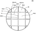
Here, fig. 1 is a perspective view schematically showing a first embodiment of the plugged honeycomb structure of the present invention, viewed from the inflow end face side. Fig. 2 is a plan view schematically showing the first embodiment of the plugged honeycomb structure of the present invention, viewed from the inflow end face side. Fig. 3 is a sectional view schematically showing a-a' of fig. 2. Fig. 4 is a schematic explanatory view for explaining the structure of the joining layer of the honeycomb structure shown in fig. 2.
The honeycomb cell 4 has porous partition walls 1 arranged to surround a plurality of cells 2, and the plurality of cells 2 extend from an inflow end surface 11 to an outflow end surface 12. The honeycomb unit 4 is configured such that: the partition wall 1 also has a cell outer peripheral wall at its outer peripheral portion, whereby its overall shape is, for example, prismatic. In the present invention, the compartment 2 is a space surrounded by the partition wall 1.
The plugged honeycomb structure 100 includes a plurality of honeycomb cells 4, and side surfaces of the plurality of honeycomb cells 4 are bonded to each other by a bonding layer 6. Among the plurality of honeycomb cells 4, the honeycomb cell 4 disposed in the central portion of the plugged honeycomb structure 100 has a "prismatic shape" whose axial direction is the direction from the inlet end face 11 toward the outlet end face 12. On the other hand, among the plurality of honeycomb cells 4, the honeycomb cell 4 disposed in the outer peripheral portion in contact with the outer peripheral wall 21 is formed in a columnar shape in which a part of the honeycomb cell 4 formed in a prism shape is ground in accordance with the shape of the outer peripheral wall 21.
The bonding layer 6 is made of a bonding material that bonds the side surfaces of the plurality of honeycomb units 4 to each other. Hereinafter, a joined body in which a plurality of honeycomb cells 4 are joined together by a joining layer 6 may be referred to as a "honeycomb cell joined body 20".
One of the ends of the cells 2 in each honeycomb unit 4 on the inflow end surface 11 side or the outflow end surface 12 side is plugged by the plugging portion 5. That is, the plugging portions 5 are disposed at the openings of the predetermined cells 2 on the inflow end face 11 and the openings of the remaining cells 2 other than the predetermined cells 2 on the outflow end face 12 of each honeycomb unit 4.
Hereinafter, the cell 2 in which the plugging portion 5 is disposed at the opening portion of the cell 2 on the inflow end face 11 of the honeycomb unit 4 (i.e., the predetermined cell 2 described above) may be referred to as an "outflow cell". The cells 2 in which the plugging portions 5 are arranged at the openings of the cells 2 on the outflow end surface 12 of the honeycomb unit 4 (i.e., the remaining cells 2 described above) may be referred to as "inflow cells". The honeycomb cell having the plugging portions 5 disposed in the openings of the cells 2 of the honeycomb cell 4 may be referred to as a "plugged honeycomb cell".
The plugged honeycomb structure 100 of the present embodiment has a main feature particularly regarding the bonding strength of the bonding layer 6 that bonds the honeycomb cells 4. Here, the honeycomb cell 4 arranged in contact with the outer peripheral wall 21 among the honeycomb cells 4 constituting the honeycomb cell assembly 20 is referred to as an "outer peripheral honeycomb cell 4 a". The bonding layer 6 that bonds the outer peripheral honeycomb cells 4a to each other is referred to as an "outer peripheral bonding layer 6 a". The bonding strength of the outer peripheral bonding layer 6a that bonds the outer peripheral honeycomb cells 4a to each other is made "bonding strength a 1". The honeycomb cell 4 including the center of gravity of a cross section of the honeycomb cell assembly 20 perpendicular to the direction in which the cells 2 extend, or the honeycomb cell 4 existing at a position closest to the center of gravity, is referred to as a "central honeycomb cell 4 b". The junction layer 6 that joins the central honeycomb cell 4b and another honeycomb cell 4 adjacent to the central honeycomb cell 4b is referred to as a "central junction layer 6 b". The bonding strength of the central bonding layer 6b was defined as "bonding strength a 2". In the central cell 4b, the "cell 4 including the center of gravity of the cross section" refers to a cell having the center of gravity located in the central cell 4 b. On the other hand, the "honeycomb cell 4 present at the position closest to the center of gravity of the cross section" of the central honeycomb cell 4b is a honeycomb cell present at the position closest to the center of gravity when the center of gravity is located on the junction layer 6, for example.
The plugged honeycomb structure 100 of the present embodiment is characterized in that: the bonding strength a1 of the peripheral bonding layer 6a is greater than the bonding strength a2 of the central bonding layer 6 b. With such a configuration, the plugged honeycomb structure 100 exhibits the following effects. That is, the occurrence of cracks along the surface of the outer peripheral wall 21 of the bonding layer 6 (more specifically, the outer peripheral bonding layer 6a) can be effectively suppressed without deteriorating the occurrence of cracks at the end faces of the honeycomb cells 4 and cracks extending in the circumferential direction on the surface of the outer peripheral wall 21.
In the case where the bonding strength a1 of the outer peripheral bonding layer 6a and the bonding strength a2 of the central bonding layer 6b are the same, if both the bonding strength a1 and the bonding strength a2 are small values, the bonding layer 6 on the outer peripheral portion of the honeycomb cell joined body 20 is likely to be cracked. On the other hand, if both the bonding strength a1 and the bonding strength a2 have large values, when high thermal stress is generated in the DPF due to the combustion heat of the PM during the regeneration process, the stress relaxation at the bonding layer 6 is insufficient, and it is difficult to suppress cracking at the end faces of the honeycomb cells 4. In addition, even when the bonding strength a1 of the outer peripheral bonding layer 6a is smaller than the bonding strength a2 of the central bonding layer 6b, the bonding layer 6 is likely to be cracked at the outer peripheral portion of the honeycomb cell joined body 20.
In the present invention, "bonding strength a1 of the peripheral bonding layer 6 a" and "bonding strength a2 of the central bonding layer 6 b" are values measured by the following measurement method. First, a method of measuring the "bonding strength a 1" will be described. First, 2 outer peripheral honeycomb cells 4a including the "outer peripheral bonding layer 6 a" to be measured were cut out from the honeycomb cell assembly 20, and a measurement sample for measuring the bonding strength a1 was prepared. The measurement sample was obtained by bonding 2 outer peripheral honeycomb cells 4a by an outer peripheral bonding layer 6 a. The end faces of the outer peripheral honeycomb cells 4a of the measurement sample were loaded at a load rate of 2mm/min using a shear load measuring instrument, and the fracture load F1 at the time of fracture of the outer peripheral bonding layer 6a was measured. Further, the area S1 of the bonding surface of the peripheral bonding layer 6a in which 2 peripheral honeycomb cells 4a are bonded was measured, and the bonding strength a1 was calculated based on the following formula (1). When the shear load F1 is measured by the shear load measuring device, a load is applied so as to support only the lower end face of one outer circumferential honeycomb cell 4a and not the lower end face of the other outer circumferential honeycomb cell 4a of the 2 outer circumferential honeycomb cells 4 a.
Formula (1): joint strength a 1-breaking load F1/area of joint S1
Next, a method of measuring the "bonding strength a 2" will be described. First, the central cell 4b including the center of gravity of a cross section orthogonal to the direction in which the cells 2 extend or the central cell 4b existing at the position closest to the center of gravity is found from the cell assembly 20. Then, the central honeycomb cell 4b including the "central bonding layer 6 b" as the object of measurement and the other honeycomb cells 4 were cut out, and a measurement sample for measuring the bonding strength a2 was prepared. The measurement sample was obtained by bonding the central honeycomb unit 4b and the other honeycomb units 4 through the central bonding layer 6 b. The fracture load F2 of the measurement sample at the time of fracture of the central bonding layer 6b was measured by the same method as the measurement of the bonding strength a1 using a shear load measuring apparatus. The area S2 of the bonding surface of the center bonding layer 6b was measured, and the bonding strength a2 was calculated based on the following formula (2).
Formula (2): joint strength a 2-breaking load F2/area of joint S2
The bonding strength A1 is preferably 1.2 to 1.6 times, more preferably 1.2 to 1.5 times the bonding strength A2. With such a configuration, it is possible to more effectively suppress the occurrence of cracks along the surface of the outer peripheral wall 21 of the outer peripheral bonding layer 6 a.
The bonding strength A1 of the peripheral bonding layer 6a is preferably 850 to 1200kPa, more preferably 900 to 1150kPa, and particularly preferably 900 to 1100 kPa. If the bonding strength a1 is less than 850kPa, it is not preferable from the viewpoint of effectively suppressing the occurrence of cracks in the bonding layer 6. On the other hand, if the joint strength a1 exceeds 1200kPa, it is not preferable from the viewpoint of suppressing the occurrence of cracks at the end faces of the honeycomb unit 4. When the bonding strength a1 is within the above numerical range, the bonding strength a1 is also greater than the bonding strength a 2.
The bonding strength A2 of the central bonding layer 6b is preferably 400 to 900kPa, more preferably 600 to 850kPa, and particularly preferably 700 to 800 kPa. If the bonding strength a2 is less than 400kPa, it is not preferable from the viewpoint of maintaining the bonding obtained by the central bonding layer 6 b. On the other hand, if the joint strength a2 exceeds 900kPa, it is not preferable from the viewpoint of suppressing the occurrence of cracks at the end faces of the honeycomb cells 4 and suppressing ring cracks. When the bonding strength a2 is within the above numerical range, the bonding strength a1 is also greater than the bonding strength a 2.
The bonding strength A1 of the peripheral bonding layer 6a is preferably 1.2 to 1.6 times, more preferably 1.2 to 1.5 times, and particularly preferably 1.3 to 1.4 times the bonding strength A2 of the central bonding layer 6 b. If the bonding strength a1 is less than 1.2 times the bonding strength a2, it is not preferable from the viewpoint of suppressing the occurrence of cracks along the surface of the outer peripheral wall 21 of the outer peripheral bonding layer 6 a. On the other hand, if the joining strength a1 exceeds 1.6 times the joining strength a2, it is not preferable from the viewpoint of suppressing the occurrence of cracks at the end faces of the honeycomb cells 4.
In the plugged honeycomb structure 100 of the present embodiment, the material of the outer peripheral joining layers 6a and the material of the central joining layers 6b may be different. The outer peripheral bonding layer 6a and the central bonding layer 6b may be configured to: the bonding strength is different between them due to the difference in porosity or the like. With such a configuration, the difference between the bonding strength a1 and the bonding strength a2 becomes clear, and the effects described above can be effectively exhibited.
The material of the bonding layer 6 is not particularly limited, and a conventionally known bonding layer material in a honeycomb structure can be used.
In the plugged honeycomb structure 100 of the present embodiment, the bonding strength a1 of the outer peripheral bonding layers 6a that bond the outer peripheral cells 4a arranged on the outermost periphery of the honeycomb cell assembly 20 to each other may be greater than the bonding strength of the other bonding layers 6. That is, the bonding strength a1 of only the outer peripheral bonding layer 6a may be larger than the bonding strength of the other bonding layers 6. However, the bonding strength a1 is not particularly limited as long as it is greater than the bonding strength a2, and the bonding strength other than the outer peripheral bonding layer 6a and the central bonding layer 6b is not particularly limited. For example, the bonding strength of the bonding layer (except for the central bonding layer 6b) that bonds 1 or 2 or more honeycomb cells 4 inside the outer peripheral honeycomb cell 4a may be the same as the bonding strength a1 of the outer peripheral bonding layer 6 a. The bonding strength of the bonding layer that bonds the honeycomb cells 4 that are 1 or 2 or more inside the outer peripheral honeycomb cell 4a may be the same as the bonding strength a2 of the central bonding layer 6 b. For example, various embodiments may be adopted in which only the "peripheral bonding layer 6a that bonds the peripheral honeycomb cells 4a arranged on the outermost periphery" has particularly high bonding strength.
As described above, the plugged honeycomb structure 100 of the present embodiment has, in a cross section orthogonal to the direction in which the cells 2 extend: an outer peripheral portion 15 including the outer peripheral bonding layer 6a having a relatively large bonding strength and a central portion 16 including the central bonding layer 6b having a relatively small bonding strength. Hereinafter, the bonding layer 6 having a relatively high bonding strength in the outer peripheral portion 15 may be referred to as a "high bonding strength bonding layer 6 x". In a cross section orthogonal to the direction in which the compartment 2 extends, the ratio of the area occupied by the high bonding strength bonding layer 6x to the total area occupied by the bonding layers 6 is preferably 5 to 55%, more preferably 10 to 50%, and particularly preferably 10 to 40%. If the ratio of the area occupied by the high bond strength bond layer 6x exceeds the above numerical range, it is difficult to obtain a balance of suppressing the occurrence of cracks in the high bond strength bond layer 6x and suppressing the occurrence of cracks in the end faces of the honeycomb cells 4 or the surface of the outer peripheral wall 21.
The "width of the bonding layer 6 in the direction orthogonal to the direction in which the compartments 2 extend" is not particularly limited. Here, "the width of the bonding layer 6 in the direction orthogonal to the direction in which the cells 2 extend" is the distance between the side surfaces of the honeycomb cells bonded by the bonding layer. Hereinafter, the "width of the bonding layer 6 in the direction orthogonal to the direction in which the compartments 2 extend" may be simply referred to as "width of the bonding layer 6". The width of the bonding layer 6 is, for example, preferably 0.3 to 3.0mm, and particularly preferably 0.5 to 2.0 mm. If the width of the joining layer 6 is less than 0.3mm, the joining strength of the plugged honeycomb structure 100 tends to decrease, which is not preferable. If the width of the joining layer 6 exceeds 3.0mm, the pressure loss of the plugged honeycomb structure 100 may increase, which is not preferable.
There is no particular limitation on the shape of the cells 2 formed in the honeycomb unit 4. For example, as the shape of the cell 2 in a cross section orthogonal to the direction in which the cell 2 extends, there can be mentioned: polygonal, circular, elliptical, etc. Examples of polygons include: triangular, quadrilateral, pentagonal, hexagonal, octagonal, etc. The shape of the cells 2 is preferably triangular, quadrangular, pentagonal, hexagonal, octagonal. In addition, the shape of the cells 2 may be the same or different for all the cells 2. For example, although illustration is omitted, quadrangular cells and octagonal cells may be mixed. In addition, the size of the compartments 2 may be the same or different for all the compartments 2. For example, although illustration is omitted, the size of some of the plurality of compartments may be increased, while the size of the other compartments may be relatively decreased.
The compartment density of the compartment 2 formed by the partition 1 is preferably 15-90/cm2More preferably 30 to 60 pieces/cm2. With such a configuration, the plugged honeycomb structure of the present embodiment can be preferably used as a filter for purifying exhaust gas discharged from an engine of an automobile.
The porosity of the partition wall 1 is preferably 30 to 80%, more preferably 35 to 75%, and particularly preferably 40 to 70%. The porosity of the partition wall 1 is a value measured by a mercury intrusion method. The porosity of the partition walls 1 can be measured using, for example, Autopore 9500 (trade name) manufactured by Micromeritics. A part of the cell wall 1 of each honeycomb cell 4 may be cut out as a test piece, and the porosity may be measured using the test piece. If the porosity of the partition walls 1 is less than 30%, the pressure loss of the plugged honeycomb structure 100 itself may increase, and the variation in pressure loss after the catalyst is supported may increase. If the porosity of the partition walls 1 exceeds 80%, the strength and trapping performance of the plugged honeycomb structure 100 as a filter may be lowered.
There is no particular limitation on the shape of the honeycomb unit 4. For example, the shape of the honeycomb unit 4 may be a polygonal prism shape such as a quadrangle or a hexagon in a cross-sectional shape orthogonal to the axial direction of the honeycomb unit 4. The honeycomb unit 4 disposed on the outermost periphery of the plugged honeycomb structure 100 may be obtained by processing a part of the prismatic shape by grinding or the like in accordance with the overall shape of the plugged honeycomb structure 100.
The overall shape of the plugged honeycomb structure 100 is not particularly limited. For example, the plugged honeycomb structure 100 shown in fig. 1 has a cylindrical shape in which the inflow end face 11 and the outflow end face 12 are circular. Although not shown, the whole shape of the plugged honeycomb structure may be a columnar shape having an inflow end face and an outflow end face in a substantially circular shape such as an oval shape, a Racetrack (Racetrack) shape, or an oval shape. The plugged honeycomb structure may have a polygonal prism shape such as a quadrangle or a hexagon in the inflow end face and the outflow end face as the whole shape.
The material constituting the honeycomb unit 4 is not particularly limited, but at least 1 material selected from the following material group is preferable from the viewpoint of strength, heat resistance, durability, and the like. The material group includes silicon carbide, silicon-silicon carbide composite materials, silicon nitride, cordierite, mullite, alumina, spinel, silicon carbide-cordierite composite materials, lithium aluminum silicate, aluminum titanate, and Fe — Cr — Al metal. Among these, silicon carbide or a silicon-silicon carbide composite material is more preferable. The silicon-silicon carbide composite material is a composite material in which silicon carbide (SiC) is used as an aggregate and silicon (Si) is used as a binder.
The material of the plugging portion 5 is not particularly limited. The material of the plugging portion 5 is preferably the same material as the material exemplified as the material constituting the honeycomb unit 4, for example.
The size of the plugged honeycomb structure 100, for example, the length from the inflow end face 11 to the outflow end face 12, and the size of the cross section of the plugged honeycomb structure 100 orthogonal to the direction in which the cells 2 extend are not particularly limited. When the plugged honeycomb structure 100 of the present embodiment is used as a filter for exhaust gas purification, various dimensions may be appropriately selected so as to obtain optimum purification performance. For example, the length from the inflow end face 11 to the outflow end face 12 of the plugged honeycomb structure 100 is preferably 150 to 305mm, and particularly preferably 150 to 200 mm. In addition, the area of the cross section of the plugged honeycomb structure 100 perpendicular to the direction in which the cells 2 extend is preferably 144 to 330mm2Particularly preferably 144 to 178mm2。
In the plugged honeycomb structure 100 of the present embodiment, the plugging portions 5 are arranged at the openings on the inflow end face 11 side of the predetermined cells 2 and the openings on the outflow end face 12 side of the remaining cells. Here, the cells 2 having the plugging portions 5 arranged in the openings on the outflow end face 12 side and the openings on the inflow end face 11 side are referred to as inflow cells. The cells 2 having the plugging portions 5 arranged in the openings on the inflow end surface 11 side and having the openings on the outflow end surface 12 side are referred to as outflow cells. The inflow compartments and the outflow compartments are preferably arranged alternately with the partition walls 1 in between. Further, it is preferable that the plugged honeycomb structure 100 has checkerboard patterns formed on both end surfaces thereof by the plugging portions 5 and the "openings of the cells 2".
In the plugged honeycomb structure 100 of the present embodiment, a catalyst may be supported by the partition walls 1 forming the plurality of cells 2. The catalyst is supported on the partition walls 1: the surface of the partition wall 1 and the inner wall of the pores formed in the partition wall are coated with a catalyst. With such a configuration, CO, NOx, HC, and the like in the exhaust gas can be made harmless by catalytic reaction. Further, oxidation of the trapped PM such as soot can be promoted.
(2) A method for producing a plugged honeycomb structure:
the method for producing the plugged honeycomb structure of the embodiment is not particularly limited, and can be produced, for example, by the following method. First, a moldable green body for making honeycomb cells is prepared. The green compact used for producing the honeycomb unit can be prepared by appropriately adding an additive such as a binder and water to a material selected from the above-described preferable materials for the honeycomb unit as a raw material powder.
Next, the green compact thus obtained was subjected to extrusion molding to produce a prismatic honeycomb molded body having partition walls arranged to surround a plurality of cells and cell outer peripheral walls arranged on the outermost periphery. A plurality of honeycomb formed bodies were produced.
The obtained honeycomb formed body is dried with, for example, microwaves and hot air, and the openings of the cells are sealed with the same material as that used for the production of the honeycomb formed body, thereby producing sealed portions. After the plugging portion is formed, the honeycomb formed body may be further dried.
Next, the honeycomb formed body with the plugged portions was fired, thereby obtaining plugged honeycomb cells. The firing temperature and firing atmosphere vary depending on the raw materials, and those skilled in the art can select the firing temperature and firing atmosphere most suitable for the selected material.
Next, the plurality of plugged honeycomb cells are bonded to each other with a bonding material, dried and cured, and then the outer periphery is processed into a desired shape, whereby a plugged honeycomb structure having a cell structure can be obtained. As the bonding material, a material prepared by adding a solvent such as water to a ceramic material to form a paste or slurry can be used. In this case, it is preferable to produce 2 kinds of bonding materials by adjusting the amount of a solvent such as water added to the bonding materials to produce 2 kinds of bonding materials having different solvent content ratios. In addition, different amounts of pore formers were added to the bonding materials, and 2 types of pore formers were prepared with different ratios of the bonding materials. If the amount of the solvent is reduced, the bonding strength of the bonding layer formed of the bonding material increases. In addition, if the amount of the pore-forming material is reduced, the bonding strength of the bonding layer formed of the bonding material increases.
The 2 types of bonding layers prepared as described above were used separately for the portion where the plugged honeycomb cells arranged on the outermost periphery were bonded to each other and the other portions, respectively, whereby the obtained plugged honeycomb structure was able to change the bonding strength of the bonding layers in the outer peripheral portion and the central portion.
Further, since the processed surface of the joined body of the plugged honeycomb cells after the outer periphery thereof is processed is in a state in which the cells are exposed, the outer peripheral coating material can be applied to the processed surface of the joined body to form the outer peripheral wall. Examples of the material of the outer periphery coating layer include inorganic materials such as inorganic fibers, colloidal silica, clay, and ceramic particles, and additives such as an organic binder, a foaming resin, and a dispersant, and water are added and kneaded to form a slurry.
[ examples ] A method for producing a compound
The present invention will be described more specifically with reference to the following examples, but the present invention is not limited to these examples at all.
(example 1)
As ceramic raw materials, silicon carbide (SiC) powder and metal silicon (Si) powder were prepared in a ratio of 80: 20 in a mass ratio of the obtained mixed raw materials. To this mixed raw material, hydroxypropyl methylcellulose as a binder and a water-absorbent resin as a pore former were added, and water was added to prepare a molding raw material. The obtained molding material was kneaded by a kneader (kneader) to obtain a green compact.
Next, the obtained green compact was molded by a vacuum extrusion molding machine to prepare 25 quadrangular-prism-shaped honeycomb molded bodies. Each 1 of the quadrangular prism-shaped honeycomb formed bodies becomes a honeycomb unit.
Subsequently, the obtained honeycomb formed body was dried by high-frequency induction heating, and then dried at 120 ℃ for 2 hours by using a hot air dryer.
Next, plugging portions are formed in the dried honeycomb formed body. First, a mask is applied to the inflow end face of the dried honeycomb formed body. Next, the end portion (end portion on the inflow end surface side) to which the mask is applied is immersed in the sealing slurry, and the opening portions of the cells (outflow cells) to which no mask is applied are filled with the sealing slurry. Thereby, the plugging portions were formed on the inflow end face side of the dried honeycomb formed body. The same procedure was applied to the outflow end face of the dried honeycomb formed body to form plugged portions also in the inflow cells.
Then, the honeycomb formed body having the plugged portions formed thereon is degreased and fired to obtain plugged honeycomb cells. The degreasing conditions were 550 ℃ for 3 hours, and the firing conditions were argon atmosphere, 1450 ℃ for 2 hours.
The plugged honeycomb cells used for manufacturing the plugged honeycomb structure of example 1 were produced as described above. The cross section of the prepared sealed honeycomb unit orthogonal to the axial direction is a square, and the length of one side (unit size) of the square is 36.5 mm. The results are shown in the column of "length (mm) of one side" of the "honeycomb cell" in table 1. In addition, the axial length of the plugged honeycomb cells was 178 mm.
For the plugged honeycomb cells, the thickness of the partition walls was 0.3mm, and the cell density was 46 cells/cm2. The porosity of the partition wall was 41%. The porosity of the partition wall was measured by Autopore 9500 (trade name) manufactured by Micromeritics.
Next, 2 kinds of bonding materials for bonding the plugged honeycomb cells were prepared. That is, the material for forming the bonding layer in the plugged honeycomb structure is the above bonding material. Hereinafter, the 2 kinds of bonding materials are referred to as "bonding material a" and "bonding material B". The bonding material A was prepared so that the bonding strength was 900 kPa. The bonding material B was prepared so that the bonding strength thereof was 700 kPa.
Next, the obtained plugged honeycomb cells were joined by a joining material in a state where the side surfaces thereof were adjacently disposed to face each other, and heat-treated at 700 ℃. The honeycomb cell assembly was prepared by bonding 25 honeycomb cells in a total of 5 cells in the vertical direction and 5 cells in the horizontal direction, which were arranged on the end face of the honeycomb cell assembly. The number of cells used in each embodiment and the arrangement thereof are given in the "number(s)" and "arrangement (s × number)" columns in "cells" of table 1. For example, when the column of "placement (number × number)" is "5 × 5", it means that 25 cells in total, that is, 5 cells in the vertical direction and 5 cells in the horizontal direction, are used.
In example 1, the above-described "bonding material a" was used when the 12 plugged honeycomb cells located at the outermost periphery of the honeycomb cell assembly were bonded to each other. The above-described "bonding material B" is used for the other bonding portions. The thickness of the bonding layer formed of the bonding material was 1.0 mm. The portion using the bonding material a was defined as the outer peripheral portion of the honeycomb cell bonded body. The portion using the bonding material B was defined as the center portion of the honeycomb cell bonded body.
Next, the outer periphery of the honeycomb cell joined body was ground into a cylindrical shape, and a coating material was applied to the outer peripheral surface thereof, to obtain a plugged honeycomb structure of example 1. The diameter of the end face of the plugged honeycomb structure of example 1 was 191 mm.
With respect to the plugged honeycomb structure of example 1, the bonding strength of the bonding layer in the outer peripheral portion and the bonding strength of the bonding layer in the central portion were measured by the following methods. The results are shown in columns of "bonding strength (kPa) in the outer peripheral portion" and "bonding strength (kPa) in the central portion" in table 2. In addition, the ratio of the joining strength in the outer peripheral portion to the joining strength in the central portion is given in the column of "joining strength ratio (outer peripheral portion/central portion)" of table 2. In addition, the ratio of the bonding area of the high bonding strength bonding layer to the total bonding area of the bonding layers is given in the column of "bonding area ratio (high bonding strength area/total bonding area)" of table 2. The high bonding strength bonding layer is a bonding layer having relatively high bonding strength in the outer peripheral portion. The high bonding strength area refers to an area of a bonding surface bonded by the high bonding strength bonding layer.
(method of measuring bonding Strength)
First, 2 peripheral honeycomb cells including peripheral bonding layers were cut out, and a measurement sample for measuring the bonding strength (that is, bonding strength a1) at the peripheral portion was prepared. The end faces of the outer peripheral honeycomb cells of the prepared measurement sample were loaded at a load rate of 2mm/min using a shear load measuring instrument, and the fracture load F1 at the time of fracture of the outer peripheral junction layer was measured. Further, the area S1 of the bonding surface of the peripheral bonding layer where 2 peripheral honeycomb cells were bonded was measured, and "bonding strength (kPa) in the peripheral portion" as the bonding strength a1 was obtained based on the above expression (1). Further, a central honeycomb cell including the central bonding layer and other honeycomb cells were cut out, and a measurement sample for measuring the bonding strength (i.e., bonding strength a2) in the central portion was prepared. The breaking load F2 of the prepared measurement sample at the time of breaking the central bonding layer was measured by the same method as described above using a shear load measuring instrument. The area S2 of the bonding surface of the center bonding layer was measured, and the "bonding strength (kPa) in the center portion" was obtained as the bonding strength a2 based on the above expression (2).
[ TABLE 1]
[ TABLE 2]
In addition, the plugged honeycomb structure of example 1 was subjected to a "rapid cooling test (electric furnace spalling test: E-sp evaluation)" and a "fracture limit evaluation" by the following methods. The results are shown in Table 3.
[ Rapid Cooling test (electric furnace spalling test: E-sp evaluation) ]
And putting the sealed honeycomb structure into an electric furnace with the temperature of 200 ℃ in the furnace, and heating for 2 hours to ensure that the sealed honeycomb structure has uniform temperature. Then, the heated plugged honeycomb structure was taken out from the electric furnace and rapidly cooled to room temperature. In the plugged honeycomb structure after the rapid cooling, it was confirmed whether or not cracking occurred in the outer peripheral wall. In the case where no cracking occurred in the outer peripheral wall, the temperature in the furnace was increased every 25 ℃, and the heating and the rapid cooling were repeated until the cracking occurred in the outer peripheral wall. The furnace temperature of the first 1 operation of the furnace temperature at which cracking occurred in the outer peripheral wall was taken as a measured value in the rapid cooling test.
[ evaluation of cracking Limit ]
The plugged honeycomb structure is mounted in an exhaust system of a diesel engine, and soot is accumulated in the plugged honeycomb structure. Next, the off-gas temperature was increased to 650 ℃ at 2 ℃/sec. Then, in the idling operation, the conditions are changed so that the gas flow rate is abruptly reduced. Under these conditions, the soot accumulated in the plugged honeycomb structure is burned to regenerate the plugged honeycomb structure. The above test (regeneration of the plugged honeycomb structure) was repeated while gradually increasing the accumulation ratio of soot in the plugged honeycomb structure. The deposition ratio of soot is a ratio of mass (g) of soot deposited in the plugged honeycomb structure per unit volume (per 1L) of the plugged honeycomb structure. Then, the maximum soot accumulation ratio at which the plugged honeycomb structure was not cracked was investigated. The soot accumulation ratio at this time was defined as "cracking limit". The case where the cracking limit was less than 6g/L was evaluated as "B". The case where the cracking limit was 6g/L or more was evaluated as "A".
[ TABLE 3]
(examples 2 and 3)
A plugged honeycomb structure was produced in the same manner as in example 1, except that a bonding material prepared according to the bonding strength shown in table 2 was used.
(examples 4 to 6)
A plugged honeycomb structure was produced in the same manner as in example 1, except that the structures of the honeycomb cells and the honeycomb joined body were changed as shown in table 1 and a joining material prepared according to the joining strength shown in table 2 was used.
Comparative examples 1 to 3
A plugged honeycomb structure was produced in the same manner as in example 1, except that 1 type of bonding material was used as the bonding material to produce a plugged honeycomb structure when producing a honeycomb cell bonded body.
The plugged honeycomb structures of examples 2 to 6 and comparative examples 1 to 3 were also subjected to a "rapid cooling test (electric furnace spalling test: E-sp evaluation)" in the same manner as in example 1. The results are shown in Table 3.
(results)
The plugged honeycomb structures of examples 1 to 3 gave better results in the rapid cooling test than the plugged honeycomb structure of comparative example 1. In addition, in the plugged honeycomb structure of comparative example 2, the bonding strength of the bonding layer was high in both the outer peripheral portion and the central portion, and good results were obtained in the rapid cooling test, but the cracking limit was less than 6g/L in the cracking limit evaluation. In addition, the plugged honeycomb structures of examples 4 to 6 can obtain better results in the rapid cooling test than the plugged honeycomb structure of comparative example 3.
[ industrial applicability ]
The plugged honeycomb structure of the present invention can be used as a trapping filter for removing particulates and the like contained in exhaust gas discharged from a direct injection gasoline engine, a diesel engine, and the like.